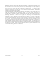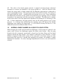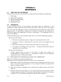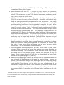
1
DIFFERENTIAL PRESSURE NULL INDICATOR MODEL 2413/2416 USER'S MANUAL RUSKA INSTRUMENT CORPORATION 10311 WESTPARK DRIVE, HOUSTON, TX. 77042 713-975-0547 FAX: 713-975-6338 e-mail: [email protected] Release: 2413-1D01 Revision: D Date: June 27, 2002 WARRANTY Ruska Instrument Corporation warrants its products to conform to or exceed the specifications as set forth in its catalos in use at the time of sale and reserves the right, at its own discretion, without notice and without making similar changes in articles previously manufactured, to make changes in materials, designs, finish, or specifications. Ruska Instrument Corporation warrants products of its own factory against defects of material or workmanship for a period of one year from date of shipment. Liability of Ruska Instrument Corporation under this warranty shall be limited to replacing, free of charge (FOB Houston, Texas), any such parts proving defective within the period of this warranty, but will not be responsible for transportation charges or consequential damages. This warranty is not made for products manufactured by others which are illustrated and described in Ruska catalogs or incorporated in Ruska products in essentially the same form as supplied by the original manufacturer. However, Ruska Instrument Corporation agrees to use its best efforts to have original suppliers make good their warranties. -ii- INTRODUCTION COPYRIGHT NOTICE Copyright 1990, 1992 by Ruska Instrument Corporation. All rights reserved. This document may not be reproduced in part or in while without the express written consent of Ruska Instrument Corporation. DISCLAIMER No representations or warranties are made with respect to the contents of this user's manual. Further, Ruska Instrument Corporation reserves the right to revise this manual and to make changes from time to time in the content hereof without obligation to notify any person of such revision. TRADEMARK NOTICE is a trademark of Ruska Instrument Corporation Trademarks or tradenames are subject to state and federal laws concerning their unauthorized use or other infringements. The fact that the product marks or names in this manual do not bear a trademark symbol DOES NOT mean that the product name or mark is not registered as a trademark or tradename. Any queries concerning the ownership or existence of any trademarks or tradenames mentioned in this manual should be independently confirmed with the manufacturer or distributor of the product. -iii- INTRODUCTION REVISION NOTICE RELEASE NUMBER REV. DATE OF RELEASE DESCRIPTION 2413-1D00 A Unknown Original release. 2413-1D00 B 09/30/90 Updated to new Manual Format 2413-1D00 C 05/12/92 Text changes. ECO 18024. 2413-1D01 D 06/27/02 Combined 2413 & 2416 manuals to form 2413-1D01, Revision D Manual. See DC/RO-23407. -iv- INTRODUCTION REVISION HISTORY RELEASE 2413-1D00, REVISION A (unknown) Original release. RELEASE 2413-1D00, REVISION B (09/30/90) Updated to new manual format. RELEASE 2413-1D00, REVISION C (05/12/92) Page 7-4; corrected part no. 2413-021 to 2413-023. ECO 18024 RELEASE 2413-1D01, REVISION D (06/27/02) Combined 2413 and 2416 manuals to form 2413-1D01, Revision D. See DC/RO -23407. -v- INTRODUCTION WARNING THE CONTROL BOX/NULL INDICATOR MUST BE SET FOR THE PROPER LINE VOLTAGE PRIOR TO CONNECTION TO A POWER SOURCE. -vi- INTRODUCTION TABLE OF CONTENTS WARRANTY .............................................................................................................. -iiCOPYRIGHT NOTICE, DISCLAIMER, TRADEMARK NOTICE........................................ -iiiREVISION NOTICE .................................................................................................. -ivREVISION HISTORY .................................................................................................. -vWARNING .............................................................................................................. -viTABLE OF CONTENTS............................................................................................ -viiSECTION 1.0 DESCRIPTION AND SPECIFICATIONS 1.1 GENERAL DESCRIPTION .....................................................................1-1 1.2 SPECIFICATIONS ................................................................................1-1 SECTION 2.0 APPLICATIONS 2.1 APPLICATIONS ...................................................................................2-1 2.1.1 Gas-to-Gas ..............................................................................2-1 2.1.2 Liquid-to-Gas............................................................................2-1 2.1.3 Liquid-to-Liquid.........................................................................2-1 SECTION 3.0 PREPARATION FOR USE 3.1 PREPARATION FOR USE ......................................................................3-1 3.2 BLEEDING LOWER CHAMBER IN A LIQUID-TO-LIQUID SYSTEM...........3-2 SECTION 4.0 OPERATION 4.1 OPERATING INSTRUCTIONS ...............................................................4-1 SECTION 5.0 PERFORMANCE OBSERVATIONS 5.1 ACTUAL SENSITIVITY VERSUS APPARENT SENSITIVITY...........................5-1 5.2 CALIBRATION.....................................................................................5-1 5.3 DETECTING LEAKS..............................................................................5-2 SECTION 6.0 MAINTENANCE 6.1 SERVICING THE INSTRUMENT.............................................................6-1 6.2 DIAPHRAGM.......................................................................................6-1 6.2.1 Replacement of Diaphragm in Model 2413 Transducer...............6-1 6.3 REPLACEMENT OF DIFFERENTIAL TRANSDUCER IN THE 2413 D.P. NULL INDICATOR...............................................................6-3 6.3.1 Failure Diagnoses .....................................................................6-4 6.4 REPLACEMENT OF TRANSFORMER ......................................................6-4 SECTION 7.0 PARTS LIST SECTION 8.0 INTRODUCTION 8.1 INTRODUCTION ................................................................................8-1 SECTION 9.0 FUNCTIONAL CIRCUIT DESCRIPTION 9.1 FUNCTIONAL CIRCUIT DESCRIPTION .................................................9-1 SECTION 10.0 TEST PROCEDURE 10.1 TEST PROCEDURE.............................................................................10-1 -vii- INTRODUCTION APPENDIX A: EXPLANATION OF TEST REPORT ...................................................A-1 APPENDIX B: DRAWINGS AND BILLS .................................................................. B-1 LIST OF FIGURES FIGURE 7-1: 2413-711 DIFFERENTIAL PRESSURE NULL INDICATOR ........................7-2 FIGURE 7-2: 2413-711 DIFFERENTIAL PRESSURE NULL INDICATOR VIEW A-A .........7-3 -viii- INTRODUCTION SECTION 1.0 DESCRIPTION AND SPECIFICATIONS 1.1 GENERAL DESCRIPTION The Differential Pressure Null Detector, composed of a Differential Pressure Transducer (2413 or 2417) and Electronic Null Indicator (2416), is designed to sense small pressure differences in both low and high pressure systems. The transducer consists of two pressure chambers, separated by a thin diaphragm. A difference in pressure in the two chambers causes a deflection of the diaphragm and a resultant signal to the electronic circuit. The signal is obtained as the output of a differential transformer whose movable core is attached to the diaphragm. The signal is not a linear function of the difference in pressure; therefore, use of the instrument for accurate evaluation of pressure differences is limited to small deflections of the diaphragm. The principle use of the instrument is intended as a null sensor/indicator with which the pressure of one medium may be precisely adjusted to that of another. Some of the advantages of the instrument are its high sensitiveness, high working pressure (15,000 psi for 2413 Series cells and 40,000 psi for 2417 Series), and its ability to withstand the full working pressure across the diaphragm without injury (15,000 psi maximum over-range pressure both series). 1.2 SPECIFICATIONS Inaccuracy: Inaccuracy is defined as the error in the null indication. It is expressed as the ratio of ∆P actually existing when the meter indicates a null, to the total cell pressure, in parts per million, or as constant ∆P -- whichever is greater. PPM 5 20 Error with calibration corrections Error without calibration corrections ∆P PSI 0.01 0.1 Sensitivity: The sensitivity is continuously variable from 2* 10-4 psi ∆P per meter division to 0.01 psi ∆P per meter division. The maximum value may exceed 2 *10-4 psi/div. because of variations in diaphragm characteristics and circuit parameters. Operating Pressure: 15,000 psi liquid or gas for 2413 Series cells; 40,000 psi for 2417 Series cells (See pressure media for limitations). Static Test Pressure: 22,000 psi for five minutes with nitrogen. The ungasketed metal seals act as relief valves when pressures exceed 22,000 psi. The bolts yield to the increased lead and permit the excess pressure to escape. All attempts at destructive testing of these units have failed. 50,000 psi for 2417 Series cells. 2413 1-1 DESCRIPTION & SPECIFICATIONS Over-Range Pressure 15,000 psi ∆P either side of diaphragm for both 2413 and 2417. Construction Material: Basic material of the transducer is one of the 400 Series Stainless Steels. Pressure Media: Lower Chamber of pressure cell -- Dry air, nitrogen, mercury, or any fluid inert to 400- or 300-Series Stainless Steels. Upper Chamber -- Dry air, nitrogen, or any fluid inert to 400- or 300-Series Steels, low-carbon iron, brass, copper, PVC, cadmium-plated steel or soft solder. Electrolytes may not be used ion the upper chamber. It is not recommended to use fluids in either cavity containing free hydrogen. The use of such fluids is hazardous because of possible hydrogen embrittlement of the cell body. (Consult the manufacturer for cells of special materials.) Temperature Range: 40o to 160o F Construction Details and Parameters:* Change in Null with Working Pressure See Specifications The stress from the applied pressure produces a displacement of the core within the transformer even though the pressure across the diaphragm may be zero. The displacement results in a shift of the apparent null with the true null and is approximately a linear function of the pressure. A calibration curve is supplied with each instrument to indicate the magnitude of the null shift. Change in Null with Over-Range Pressure <0.05 psi The null change with over-range pressure arises from dimensional variations within the cell body. The value shown represents the maximum expected change when the cell is over-ranged from alternate sides of the diaphragm. In practice, a procedure is used that permits intentional over-ranging from only one side. After several such applications of over-range pressure from the same side, null indication becomes stable. If the cell is accidentally over-ranged from the * opposite side, there is no harm except for a temporary loss of the original null setting. The cell must then be over-ranged from the original side to re-establish the true null. * Values shown under this heading are nominal at time of this publication and are not to be considered as binding specifications. They are subject to change with improvements in design and technoclo DESCRIPTION & SPECIFICATIONS 1-2 2413 Approximate Range of ∆P: +/-2 psi Volumes of Cavities: Upper -- 29.5 cc Lower -- 0.6 cc Effective Diameter of Diaphragm: 1.9 inches Thickness of Diaphragm: 0.001 inch Types of Fittings: For 2413 Series, Ruska 60# cone with 3/8-24 straight thread -- male cone on fitting, female cone in body of cell. Fittings and nut for 3/16 stainless steel 60# flared tubing. For 2417 Series, NBS threaded cone fittings. 2413 1-3 DESCRIPTION & SPECIFICATIONS THIS PAGE INTENTIONALLY LEFT BLANK DESCRIPTION & SPECIFICATIONS 1-4 2413 SECTION 2.0 APPLICATIONS 2.1 APPLICATIONS The Model 2416 may be employed as a null detector/indicator in the following manner: 2.1.1 GAS-TO-GAS The instrument may be used with dry air, nitrogen, carbon dioxide, some hydrocarbons, and the noble gases, but not with gases containing free hydrogen or oxygen. Although oxygen will not directly attach the materials of the lower cavity, there is the danger that an accidentally perforated diaphragm will permit the oxygen to enter the upper cavity. The organic materials in the upper cavity propose a hazard in the presence of compressed oxygen. In all instances where a gas is used, no liquid vapors should be permitted to enter the diaphragm cavity, as the surface tension effects of condensed vapors will surely spoil the performance of the diaphragm. 2.1.2 LIQUID-TO-GAS As a rule, the instrument is used to separate a liquid pressure medium from a gas. The ungasketed diaphragm seals and the small volume of the lower diaphragm cavity are features included for the requirements of PVT determinations. Transducers with special electrical connections (for submerging in a liquid temperature bath( are available for PVT experiments. When used with a dead-weight gage, the transducer affords a means of calibrating elastic sensors with inert gases. The sensors, such as transducers and bourdon-tube gages may then be used in systems containing oxygen. 2.1.3 LIQUID-TO-LIQUID The Differential Pressure Transducer may be employed as a null detector between two liquid systems. For instance, when calibrating elastic sensors prepared for oxygen service, it is sometimes more convenient to use a liquid pressure medium than to use a gas. The liquid medium, of course, must be chemically inactive in the presence of oxygen in all concentrations. Mixtures of the volatile fluorocarbon solvents are frequently used for this purpose. The system containing the fluorocarbon may be balanced against the oil dead-weight gage system to pressures as high as 40,000 psi. Such systems are somewhat more economical than equivalent liquid-to-gas systems, since the pressurizing apparatus is less expensive. With the possible exception of use with the highly volatile fluorocarbons, it is not recommended that a cell be purchased for alternate use in liquid-to-liquid and liquid-togas service. In order for the cell to perform properly, the diaphragm cavity must be either completely filled with liquid, or it must be completely dry. A trace of liquid in the otherwise dry cavity will upset the performance as quickly as will an air bubble in the liquid cavity. In each instance, the surface tension effects are greater than the ∆P error signal being observed. 2413 2-1 APPLICATIONS Whenever a liquid is used in either side of the transducer, an open tube manometer must be connected in such a way that the pressure across the diaphragm may be adjusted to zero and that the meter may also be adjusted to indicate zero. In a liquid-to-liquid system, two manometers must be used -- one in each of the liquid systems. Manometers suitable for this purpose are available. A special application of the differential pressure null indicator is one i which the unit is used when cross-floating two dead-weight gages. A by-pass valve arrangement is provided for the purpose of directly connecting the two gags while making preliminary balancing adjustments. When the two gages are at pressure and approximately balanced, the valve is opened and the electrical zero adjusted. The valve is then closed and the balancing operation continued, while observing the residual pressure difference on the meter. As the pressures become more nearly equal, the valve is opened to verify the correct zero adjustment and then closed and opened alternately until no difference in meter readings is observed when the valve is either open or closed. The resolution of the entire system is quickly determined by placing a small weight on one gage and observing the effect on the meter. When using the transducer for this purpose, calibration of the null shift with working pressure is unnecessary. APPLICATIONS 2-2 2413 SECTION 3.0 PREPARATION FOR USE 3.1 PREPARATION FOR USE Normally, when a transducer is shipped from the factory, it has been calibrated with nitrogen and is dry in both cavities. Before installation, a quick performance tests may be made by first connecting the box to the cell, with power on, adjusting the sensitivity to maximum and the meter to zero. By pressing against the end of the open fittings with the finger, the meter will be seen to deflect. The effect will be less when pressing on the upper fitting, since the upper cavity has a volume some fifty times greater than the lower cavity. At maximum sensitivity, it should be relatively easy to deflect the meter from zero to full scale when pressing on the lower fitting. Because of the small volume, it is of some advantage to connect the lower cavity to the gas portion in a liquid-to-gas system. When so connected, less work will be done in raising the gas pressure. All fluids should be filtered before their introduction into the pressure system. A small, hard particle, such as metal chip, in the diaphragm cavity will perforate the diaphragm when the cell is over-ranged. Every effort should be made to keep contaminating particles out of the transducer. In charging the upper cavity with a liquid, it is important to displace most of the air with the liquid. There are many traps in the cavity which may retain small air bubbles. If these bubbles remain in contact with the diaphragm or stem which carries the transformer core, the performance will be erratic. The fact that the air bubbles dissolve in the liquid when the pressure is increased may be used to an advantage. With the vent plug removed, the liquid is pumped into the upper chamber until it appears at the vent port. The plug is replaced and the pumping continued until he pressure in the liquid system reaches 150 atmospheres or so. At this pressure, the entrapped bubbles dissolve in the liquid, forming a concentrated solution in the vicinity of the trap. Some time should be allowed for the solution to diffuse so that, when the pressure is released, the bubbles will not reappear in the same trap. The bubbles must reappear at some new point where they may rise to the top of the chamber and be expelled through the vent port. The presence of a bubble in the top of the cell cavity does not affect the measurement significantly, but it does affect the response. It is therefore convenient to work the air out of the cavity as much as is practical. The cavity may also be charged by first evacuating and then admitting the liquid to the evacuated chamber. Usually, some small bubbles still remain because of the difficulty in reducing the internal pressure sufficiently through the small-bore tubing. The presence of remaining air in the cavity may be measured if the liquid pressure generator is a screw-type displacement pump and the system contains a Bourdon-tube reference gage. It is first necessary to measure the air that exists in the portion of the liquid system other than the transducer. To make this measurement, it is necessary to isolate the liquid system from the cell and the dead-weight gage (if one is used). If there is no valve on the line to the cell, the line must be temporarily disconnected and stopped 2413 3-1 PREPARATION FOR USE off. The valve to the liquid supply reservoir is opened and the plunger advanced somewhat to remove the backlash in the pump spindle nut. With the reservoir valve closed, the screw crank is slowly rotated until the Bourdon gage pointer is observed to move a perceptible amount. The quantity of motion of the screw is noted. The motion of the crank should be small -- something like one-quarter turn or less. After reattaching the differential transducer to the system and pressurizing the opposite cavity to several hundred psi, the experiment with the screw pump is repeated. The difference in rotation of the screw crank in the two experiments represents the quantity of air remaining in the cell. In these experiments, the gage pointer must not be resting against a pin at zero pressure. It is obvious that pressurizing the opposite cavity will prevent the flexible diaphragm from spoiling the experiment. It is not difficult to keep the free air in the differential pressure transducer below 0.05 cc. 3.2 BLEEDING LOWER CHAMBER IN A LIQUID-TO-LIQUID SYSTEM When charging the small cavity beneath the diaphragm, a bias pressure is placed in the upper cavity to force the diaphragm against the lower cavity surface. After the plug beneath the cell is loosened, some liquid is forced into the lower fitting until the liquid appears around the plug threads. This method is adequate in most instances. A small bubble is trapped in the vertical section of the input port to the lower cavity; but after pressurizing the liquid for a period and repeating the process, the bubble is mostly displaced or dissolved. For more thorough displacement of the air, the cell should be inverted. PREPARATION FOR USE 3-2 2413 SECTION 4.0 OPERATION 4.1 OPERATING INSTRUCTIONS In comparing the pressure of one system to that of another, it must first be established that the comparator or indicating device is adjusted correctly. The adjustment must assure the operator that all hydraulic and pneumatic heads have been accounted. With the transducer connected between two systems and prepared for operation, the power is turned on and the circuit allowed to warm up for ten minutes. A sequence of operations must be adopted in which one of the systems is always at a higher pressure than the other during the period of change from one pressure to another. If there is a choice, it is of some advantage, in a liquid-to-gas system, to maintain the higher pressure in the liquid system during the period of change. This procedure is not difficult to execute for both increasing and decreasing changes in pressures. If it is intended to raise both system pressures from one level to a higher one, the liquid pressure is raised first to a value somewhat below the final one. The diaphragm of the differential pressure cell is driven to the lower cavity surface where it supports the excess liquid pressure. The operator is then free to concentrate on raising the gas pressure to, but not in excess of, the liquid pressure. As the final pressure is approached, it is usually possible to raise both systems simultaneously, while keeping them sufficiently balanced for the meter pointer to remain on scale. Before starting a measurement on a liquid-to-gas system, the differential pressure transducer is intentionally over-ranged in the direction proposed by the adopted procedure; i.e.; from the liquid side. The pressure is allowed to remain for a minute or so and then released. In some manner, the liquid system must be opened to atmosphere at a point level with the diaphragm. An open-tube manometer valve opened and the gas system also opened to atmosphere, the liquid is adjusted to stand in the tube at the height of the diaphragm. Under these conditions, the pressure across the diaphragm is zero. The electrical circuit, with sensitivity set at maximum or whatever value has been chosen, may then be adjusted for the meter to indicate zero ∆P. As the manometer valve is closed, the pumping action of the stem causes the liquid to rise slightly in the tube and the meter pointer to deflect. The deflection is a normal one which results from the disturbance of the liquid in the tube. Before the measurement is begun, the sensitivity is reduced by placing the shunt switch in the ON position. The shunt switch reduces the gain of the circuit by a factor of approximately 1000. First the liquid pressure and then the gas pressure is raised in the manner described above. As the gas pressure becomes approximately equal to that of the liquid, it will be observed that the two pressures will rise simultaneously as the increase in gas pressure is continued. At this time, the diaphragm is being forced away from the lower cavity surface by the gas. The displacement of the diaphragm increases the pressure in the liquid system. Although the two pressures are approximately equal, a signal will not appear on the meter until the gas pressure is within 2 psi of the liquid, since this figure is the limiting value of the indicated differential pressure. Some liquid 2413 4-1 OPERATION must be withdrawn from the differential pressure cell, allowing the diaphragm to move toward the center of the cavity whereupon the meter signal will approach the zero. If a dead weight gage is connected in the system, the pressure in the liquid may build up high enough to float the weights. With a slight excess of gas pressure, the diaphragm will then move freely across the cavity; the weights will be seen to rise rapidly. After the sensitivity is increased, by placing the shunt switch in the OFF position, the two pressures may be brought to a satisfactory balance. The increase in pressure of the two fluids is accompanied by an increase in temperature. As the fluids give up their excess heat to the apparatus, each suffers a reduction in energy. While the piston gage is floating, however, it acts as a regulator and holds the pressure of the liquid approximately constant. The shrinkage of the liquid from its loss in heat is reflected as an increase in the normal sink rate of the piston. The gas, being confined to a single-ended system, suffers a loss in pressure as it gives up its excess heat. The net effect is an unstable condition in which the indicator will signal a continuous reduction in the gas pressure as through the system were leaking. For rather large changes in the pressure level, the balance indication will approach a high state of excitement for the first minute or so. Complete stabilization will require a period of up to one hour but, for calibration purposes, manual control of the gas will be possible after only a few minutes. In reducing the pressure, the procedure is reversed. The gas pressure is first reduced and then followed by the liquid pressure. At the conclusion of the measurement, some time must be allowed for the transducer to recover before the zero-pressure conditions are verified. Particularly, if the last reduction in pressure is of one or more thousand psi, the recovery period may be as much as 5 to 10 minutes. A considerable quantity of heat is exchanged in the reduction process. The procedure for operating a liquid-to-liquid system is much the same as described above, except that a second manometer is required in the second liquid portion of the system. When adjusting the differential pressure unit at the beginning of the test, both manometers must be opened to atmosphere and each liquid adjusted to the height of the diaphragm. It must be remembered that the density of the one liquid is often different from that of the other; the total head correction must consider the two densities with their interface at the diaphragm. OPERATION 4-2 2413 SECTION 5.0 PERFORMANCE OBSERVATIONS 5.1 ACTUAL SENSITIVITY VERSUS APPARENT SENSITIVITY Although the differential pressure indicator is regarded as a null-indicating instrument, the degree to which a true null may be achieved depends upon the readability of the error signal displayed on the meter. In order to obtain a readable error signal, the diaphragm must move. The sensitivity of the instrument is expressed as the change in pressure divided by the corresponding change in meter reading -- the change in meter reading being a function of the motion or displacement of the diaphragm. The sensitivity must be determined in such a way that the tension in the diaphragm, resulting from the applied pressure, is the only restoring force which re-establishes equilibrium When one side of the diaphragm is opened to atmosphere and a small increment of pressure is applied to the other side, the diaphragm will move under the influence of the applied pressure. The motion will continue until the forces tending to move the diaphragm are equally opposed by the forces of tension in the diaphragm tending to resist the motion. The sensitivity is then equal to ∆P divided by the change in meter reading. When one side of the diaphragm is connected to a single-ended system containing a gas under pressure, the circumstances are different. The forces of an applied pressure increment tend to move the diaphragm as before, but the forces resisting the motion are greater than before. As the diaphragm moves, the volume of the single-ended system is reduced and its pressure increased. The ∆P that was applied to the diaphragm is automatically diminished and the instrument sensitivity appears to be less than before. An example of the extreme case is one in which the single-ended system is completely filled with a non-compressible liquid. As the pressure is increased on the opposite side of the diaphragm, the liquid will not permit the diaphragm to move. In this instance, the sensitivity will appear to be very poor, but the actual sensitivity is no different than when measured under ideal conditions. 5.2 CALIBRATION The calibration procedure consists of determining he pressure coefficient of the transducer, the maximum sensitivity, and the zero shift that accompanies alternate overranging pressures on the diaphragm. The pressure coefficient is usually small -- on an average, being less than 10-5/psi. When the transducer is used in a bi-fluid system, for the calibration of elastic pressuremeasuring devices, the error of the transducer can often be disregarded. When used in an apparatus for basic PVT studies, the coefficient is significant and its expression is of more value if reported in units of diaphragm displacement per unit of pressure level rather than as a change in pressure differential per unit of pressure level. For very small samples, the displacement of the diaphragm can result in an intolerable change in the sample volume, and the error will not be corrected by an adjustment of the pressure in 2413 5-1 PERFORMANCE OBSERVATIONS the amount indicated by a pressure correction curve. A calibrating procedure in which the diaphragm presumably can be restored to its isostatic position by a physical adjustment of the electrical sensing-indicating circuit has been adopted. The procedure involves simultaneous pressurization of both sections of the transducer from a common source and measuring the correction required to maintain a null indication throughout a range of pressures. The correction is applied as a change in the ten-turn zero adjusting potentiometer, the shaft of which is equipped with a turn-counting graduated dial. In practice, the dial knob is set near one end of its range and the transformer of the pressure cell adjusted to indicate an approximate null when the diaphragm is exposed to atmospheric pressure on each side. At each pressure level of operation, the dial is changed by an amount obtained from the calibration curve. The curve is plotted as the change in dial units as a function of operating pressure. Usually, it is necessary to decrease the dial registration as the pressure is increased. The advantage of maintaining a more uniform volume of the sample by accepting the method of calibration just described outweighs the convenience of correcting the data by a computer adjustment of the errors in pressure resulting from the strain in the transducer. Manual adjustment of the potentiometer becomes a part of each measurement and must not be overlooked. 5.3 DETECTING LEAKS The differential pressure unit may be used to indicate a change in pressure of one system with respect to that of another. The change may result from a leak or from a change in temperature. When the instrument is used for detecting leaks in a system, sufficient time must be allowed to eliminate temperature effects. Also, a leak in a liquid system will have a different rate indication than a leak of the same magnitude in a gas system. Some caution must be exercised when interpreting the results of this type of test. PERFORMANCE OBSERVATIONS 5-2 2413 SECTION 6.0 MAINTENANCE 6.1 SERVICING THE INSTRUMENT Failure of the instrument may result from a malfunction of the following components: 1. 2. 3. 4. 5. Diaphragm Differential Transformer Electrical Feed-Throughs Connecting Cable Electronic Circuit 6.2 DIAPHRAGM In most instances, failure of the transducer has been traced to perforations in the diaphragm caused by particle contamination of the fluids. When the cell is over-ranged from one side, the diaphragm is driven to and pressed firmly against the surface of the opposite cavity. If a particle of sufficient size is present in that cavity, the impression of the particle against the diaphragm will cause a perforation. The diaphragm must, of course, be replaced. A perforated diaphragm may be detected from one or more of the following symptoms: [A] Liquid-to-Gas System 1. Otherwise unexplained presence of gas in the liquid portion of the cell. 2. Continuous increase in liquid pressure when the cell is over-ranged from the gas side. 3. Erratic behavior of the cell caused by traces of liquid in the gas cavity. 4. A wet bore in the fitting to the gas cavity -- an indication that the liquid has migrated as far as the fitting. [B] Liquid-to-Liquid System Periodic physical tests on one of the liquids to detect the presence of contamination by the other liquid; i.e., a fluorescent residue from an evaporated sample of Freon in a Freon-to-oil system. 6.2.1 REPLACEMENT OF DIAPHRAGM IN MODEL 2413 TRANSDUCER (Refer to 2413 Parts List and Sectional Diagram.) Replacement of the diaphragm should be carried out on a clean bench. 1. Remove the circular cast base and unscrew the three supporting studs from the cell body. The studs may be grasped in a vise, the jaws of which are covered with brass or aluminum plates. 2. Wash the cell down thoroughly on the outside with a volatile solvent and dry with clean air. 3. Grasp the flats of the cell firmly in a vise, the jaws of which are protected. Pieces of paper against the flats will help prevent the polished surfaces from becoming scratched. The cell should be grasped beneath the cable receptacle. 2413 6-1 MAINTENANCE 4. Remove the upper body, Part 2413-1-8, Symbol 1 of Figure 7-2, and lay it aside, inverted, on a clean piece of paper. 5. Remove the cell from the vise. If a liquid has been used in the transformer changer, pour out the remaining liquid and flush the chamber with a mild solvent.* Do not remove any part of the electrical connectors, and be very careful not to disturb any of the internal wires. 6. With the cell inverted in the vise, carefully remove the bottom body closure, Part (20). Do not touch the cavity surface of Part (20). A metallic seal is effective only when the sealing surfaces are well polished and free of scratches. The sealing surfaces of the diaphragm and cavity have been polished in a circular direction and the resulting pattern must be maintained to accomplish the seal. When cleaning the surfaces, a soft paper wiper (Kleenex) saturated with a solvent may be used in a circular motion. Such a motion will avoid producing radial hairline scratches and an invitation for leaks. The cavity surfaces should be kept upward and covered when placed on the table. The diaphragm usually remains in the middle body (17). Examine the diaphragm, before removing it, for impressions or perforations from solid particles. The direction of the impression will indicate from which side the perforation was made. Usually the particle that caused the perforation may be located and identified. Carefully lift the diaphragm out and examine the contents of the other cavity. If particles are present, some effort should be made to identify them for the purpose of eliminating their source. Metallic particles, in particular, have a way of appearing mysteriously in places where it is certain that none previously existed. It is suspected, for instance, that the action of valve stems within their bodies are the source of some particle contaminants. Do not remove the core from the stem. 7. Immerse all parts in trichloroethylene** or Freon TF and allow to soak several minutes. Direct a stream of the solvent from a plastic ear syringe directly at the transformer assembly. The transformer is vented and some solvent may carefully be flushed into the vents with the syringe. Do not touch the wires, as they are fragile. Direct a stream through the hole from the lower side of the central body toward the corrugated springs (11) and (12). 8. Referring to the diaphragm, measure the distance from the transformer core to the top s*urface of the diaphragm or to the top of the attached button. Transfer the core to a position on the stem of a new diaphragm equal to that on the stem of the old diaphragm. It is not difficult to duplicate the position to within .01 or .02 inch, at which point the core will be within the range of adjustment of the transformer. The split core sleeve is held in position by friction and is not difficult to remove with the fingers. If the friction appears to be insufficient, the sleeve may be squeezed slightly to reduce the inside diameter before installation on the new stem. * Statements referring to the effects of liquids are not applicable to the Model 2413-751, which is used only with a gas. **Trichloroethylene has been declared toxic by Occupational Safety and Health Administration - Use only with proper precautions. MAINTENANCE 6-2 2413 9. Clean the diaphragm and cavity surfaces as described in Operation 6, and blow off all lint particles with a clean ear syringe or dust bulb. Examine the assembly under a good light for clinging particles of lint. Insert the preformed diaphragm in the cavity recess of the middle body (17), and place the bottom cap (20) upon the diaphragm while guiding the orienting pin into its hole. Insert 4 screws, equally spaced, and pull them down evenly until it is certain that the sealing surfaces are in good contact. With the assembly in an erect position, check the motion of the diaphragm by pumping air against the lower fitting with the syringe or with a short piece of clean rubber tubing sealed off on the outer end and squeezed. The motion will be visible by observing the end of the stem from above the transformer. The motion of the stem should be truly axial with very little side motion -- surely not enough to interfere with the bore of the transformer. Insert the remainder of the screws and snug them up lightly to the head. If the motion of the stem previously observed was not axial but appeared to bob in one direction, the screws on the opposite side of the direction of bob may be pulled up first and perhaps a little more than the others. Sometimes this procedure will correct or reduce the tendency for the undesirable motion. Place the cell, bottom up, in the vise and proceed to tighten the bolts. A systematic procedure must be followed to assure uniform results in the tightening process. Pull the four initial bolts up hand tight with a standard hex key, working across and then around the bolt circle. Pull up the remaining bolts in the same manner. When all bolts are hand tight, start tightening with a torque wrench in 5 foot-pound increments until the circle is complete at 35 foot-pounds. Make one additional cycle at 35 foot-pounds. 10. Before replacing the top body, attach the cable to the cell, turn the power on, and allow circuit to warm up a few minutes. Set the zero control near the high end of the range -- about 800 -- and gain to maximum. (Shunt switch in OFF position.) Adjust the position of the transformer by means of the pinion (16) until the meter indicates approximately zero*. 11. Replace the cap, and torque the bolts down to 35 foot-pound in the same manner as described in 9 above. Since the cap (1) is sealed with an O-ring, the tightening procedure is not as critical as then when securing the lower cap (20). 6.3 REPLACEMENT OF DIFFERENTIAL TRANSFORMER IN THE 2413 D.P. NULL INDIC*ATOR A serious effort has been directed toward the construction of a differential transformer which is capable of continuous operation at high ambient pressures. Notwithstanding a thorough inspection and performance test at the factory, a transformer occasionally breaks down under the severe conditions within the cell. * NOTE: For permanency of adjustment, the final rotation of the pinion must be in a clockwise direction. When the pinion is rotated clockwise, the backlash is removed from the mounting threads in a direction as to oppose the compression of the springs. At least 1/2 revolution of the pinion is necessary to be assured the backlash is completely eliminated. 2413 6-3 MAINTENANCE 6.3.1 FAILURE DIAGNOSES Some transformers have been known to fail at high pressure and to resume operation at a lower pressure. Failure is usually traced to an opening in one of the windings. A symptom-remedy table is given which describes tests to be made for defective transformers. Symptom Reason for Failure Test & Correction Procedure Transducer cell insensitive to Open Primary a change in pressure. Meter can be zeroed with zero adj. Measure DC resistance between pin-socket A (Ground) to B. If resistance greater than 1000 ohms, primary is open. Normal primary resistance 310 ohms.* Replace transformer. Meter pointer hard against Open Secondary pin. Cannot be brought to zero with zero adj. Cell insensitive to pressure Measure DC resistance between pin-socket C (Ground) to D and C to F. Normal resistance of one secondary winding is 105 ohms. A high resistance of either winding indicates coil is open. Replace transformer The occasion on which the transformer windings open at high pressure will exhibit the above symptoms temporarily above some value of pressure. The meter pointer will be seen to dive to the pin as the pressure is increased. When the meter becomes uncontrollable at high pressure, the cable connector may be removed from the cell (or the box) and the above tests made while the cell is under pressure. Occasionally, after a prolonged period of over-ranging pressure of the diaphragm in the direction of a liquid medium, it is possible for the diaphragm to stick to the cavity surface. With the diaphragm in this position, the cell displays the same symptoms as those of a defective transformer. The resistance tests will indicate which of the conditions exist. 6.4 REPLACEMENT OF TRANSFORMER Refer to 2413 Parts List and Sectional Diagram (Figure 7-1 and 7-2). Replacement of the transformer should be performed on a clean bench. 1. Wash the cell down thoroughly on the outside with a volatile solvent and dry with clean air. 2. Grasp the flats of the cell firmly in a vise, the jaws of which are covered by brass or aluminum plates. Pieces of paper against the flats will help prevent the polished surfaces from becoming scratched. The cell should be grasped beneath the cable receptacle. 3. Remove the upper body, Part 2413-1-1, and lay it aside, inverted, on a clean piece of paper. MAINTENANCE 6-4 2413 4. Remove the cell from the vise and pour the liquid from the cavity. While holding the cell semi-inverted -- about 45# with bottom up -- over a rather large container, direct a stream of solvent (Freon TF or TRICHLOR**) into the cavity and particularly around the feed-through terminals. A 2- or 3-ounce plastic ear syringe is suitable for this purpose. The reason for inverting the cell while flushing is to prevent any solid contaminates that may have come to rest in the transformer chambers from being washed into the diaphragm cavity. 5. Mark the sectional diagram with the proper wire colors for the transformer leads. Carefully lift the wires off the feed-through terminals, using a 25-watt pencil type soldering iron. As each wire is lifted, measure the resistance of the feed-through terminal to ground. The resistance should be greater than 1 megohm. The terminals should not be overheated with the iron, since the gasket will be damaged. If there is any reason to believe that the resistance measurements in the previous section could be confused by an abnormally low resistance to ground by way of the feed-through terminals, the resistance measurements should be repeated at the transformer leads before the transformer is completely removed. 6. Remove the wires from ground. 7. Remove part (symbol) 5, detent. 8. Turn the pinion, symbol 16, counterclockwise while preventing transformer from rotating with the other hand. Do not bend the wires where they are attached to the transformer. Continue to turn until the transformer is free. 9. Remove the transformer and flush the cell again as in Operation 2. disturb the core on the diaphragm stem. Do not 10. Insert the new transformer. The wires may be somewhat loner than the original ones, but it makes no difference; it is not necessary to shorten them. 11. Solder the wires to the terminals following the color code on the diagram (See Operation 5). Try to prevent oxides and excess flux from dropping into the cavity. If necessary, flush the cavity when the soldering is complete. Replace the detent. 12. Make the primary and secondary resistance tests. 13. Plug the box in, and allow the circuit to warm up. a. Set the gin to maximum. b. Set zero control to 800 or so. c. Rotate the pinion (16) until the meter reads zero.* 14. Wash the upper body and bolts and replace the O-ring in the cap if it shows evidence of extrusion. Do not use a hard, metal object to remove the O-ring: use a toothpick or wood match. ** ** Trichlorethylene has been declaried toxic by Occupational Safety and health Administration - use only with proper precautions. * See note regarding trichloroethylene. 2413 6-5 MAINTENANCE 15. With the cell in the vise, assemble the upper body and torque the bolts down evenly to 35 foot-pounds. 16. Connect the box to the cell and test the performance by pressing the finger against the end of the lower fitting. At maximum sensitivity, it should be possible to pin the meter from zero by pushing against the fitting; this is a very rough quantitative test. MAINTENANCE 6-6 2413 SECTION 7.0 PARTS LIST When ordering parts, refer to Figures 7-1 and 7-2 on pages 7-2 and 7-3 to determine reference symbol. Ruska stock number corresponding to the reference symbol will be found listed on page 7-4. Serial number of the instrument and Ruska stock numbers of parts required must accompany all orders for replacement. When returning the instrument to the factory for servicing, the indicator/control circuit must always accompany the transducer. 2413 7-1 PARTS LIST FIGURE 7-1 2413-711 DIFFERENTIAL PRESSURE NULL INDICATOR PARTS LIST 7-2 2413 FIGURE 7-2 2413-711 DIFFERENTIAL PRESSURE NULL INDICATOR 2413 7-3 PARTS LIST PARTS LIST DIFFERENTIAL PRESSURE CELL SYMBOL DESCRIPTION QTY. 1 Upper Body 2 Socket Cap Screw 12 70-229 (3/8 x 1-1/4) 3 Socket Cap Screw 3 70-122 (#4 x 3/4) 4 Terminal Block 1 2413-1-16 5 Detent 1 2413-1-4 6 Round Head Screw 1 71-132 (#4 x 5/16) 7 Differential Transformer Assy. 1 2413-020-0 8 Adjustment Gear 1 2413-1-3 9 Transformer Armature 1 86-396 10 Washer 1 2413-1-14 11 Wave Washer 1 2413-1-11 12 Washer 1 2413-1-13 13 Diaphragm Assembly 1 2413-012 14 Tube Plug 2 2118-1-1 15 "O" Ring 1 54-900-035 16 Adjustment Pinion 1 2413-1-5 17 Middle Body 1 2413-1-6 18 Dowel Pin 2 59-119 19 Transformer Block 1 2413-1-1 20 Lower Body 1 2413-1-7 21 Socket Cap Screw 12 22 Round Head Screw 2 70-120-05-06 (#4 x 1/2) 23 Lead Thru Assembly 3 2413-023 24 Coupling Body 2 2103-1 25 Tube Nut 2 2113-1-1 26 Receptacle 1 14-814 27 Round Head Screw 1 70-110-05-06 (#2 x 3/16) N/Shown Screwdriver 1 71-490 N/Shown Transducer Support Assy. 1 2413-3 PARTS LIST 1 RUSKA STOCK NO. 7-4 2413-1-8 70-230 (3/8 x 1-1/2) 2413 SECTION 8.0 GENERAL INFORMATION 8.1 INTRODUCTION This instrument employs contemporary time-proved analog techniques. The components were chosen for their long-term stability and reliability. Numerous test points exist on the circuit board that facilitate trouble-shooting when necessary. The operational amplifiers are plug-in, which allows for easy installation. The 15-volt DC system is powered by a modular power supply which is, in turn, fully isolated from line voltages through a dual primary input isolation transformer. The input line voltage, 120 Vac or 230 Vac at 50 Hz or 60 Hz, is selectable by means of a small circuit board located internal to the power cord receptacle. Removal of the power cord allows access to the fuse and circuit board compartment. The front panel controls include a power switch and indicator, a 3.5-inch null meter, a ten-turn ZERO potentiometer with calibrated dial, a ten-turn GAIN potentiometer with calibrated dial, and a SHUNT switch that allows discrete high and low gain selection. 2416 8-1 GENERAL INFORMATION THIS PAGE INTENTIONALLY LEFT BLANK GENERAL INFORMATION 8-2 2416 SECTION 9.0 FUNCTIONAL CIRCUIT DESCRIPTION 9.1 FUNCTIONAL CIRCUIT DESCRIPTION The excitation signal to the primary coils of the LVDT is generated by an oscillator made of Z2A and Z2B. The output of the oscillator (at TP7) is a 24 volt peak-to-peak sinusoid at a frequency of 5.1 KHz. This signal is attenuated by R5 and R6 and buffered through Z1B. The excitation signal (TP6) to the primary coil has a magnitude of 4 volts (P-P). The output of the LVDT is measured differentially and amplified by Z4B. This error signal is then again amplified by Z4A. The information present at the output of Z4A is a sinusoid whose amplitude and phase (0o or 180o) is a function of the position of the core in the LVDT. This information is half-wave rectified by Q1. Q1 is operated by the squarewave generator Z1A. The result at TP5 is a positive or negative half-wave sinusoid whose amplitude is a function of core displacement from the null position and whose polarity is a function of the direction of the core displacement. The signal at TP5 is then integrated by R8 and C5. This DC level is then amplified through Z3. The gain of Z3 is controlled by the GAIN adjustment. The ZERO adjustment provides a bias voltage added algebraically to the error signal via Z3. Resistor R29 and diodes CR3 and CR4 provide current and voltage limiting to the null meter. R30 is a current limiter to the recorder output jack. Resistors R25, R26, R27, and R28 determine the ZERO control sensitivity and span. 2416 9-1 FUNCTIONAL CIRCUIT DESCRIPTION THIS PAGE INTENTIONALLY LEFT BLANK FUNCTIONAL CIRCUIT DESCRIPTION 9-2 2416 SECTION 10.0 TEST PROCEDURE Reference to Drawing Nos. 2416-60-200 and 2416-63 is recommended. A DC voltmeter with .001 volt resolution is sufficient for the single required potentiometric adjustment. For trouble-shooting, an oscilloscope will be required. All measurements are made with respect to TEST POINT 2 (TP2). 1. Setup Procedure 2416 A. Set Gain control to maximum (full clockwise). B. Set ZERO control to mid-point. C. Set SHUNT to ON. D. Connect the transducer. E. Turn power ON. F. Observe the voltage at TP4. Adjust P1 to yield minimum DC volts. G. Adjust the transformer in the transducer until the meter indicates null. It must be noted here that, for oil-filled transducers, insertion of the screwdriver will affect null position. The oil displaced by the screwdriver will create a pressure head. The head must be considered. The head pressure will become more important as the test procedure progresses to the stages of higher amplification. H. Set SHUNT to OFF. This condition provides maximum amplification of null sensing. I. The final adjustment of the transducer transformer prepares the instrument for use. The accuracy with which the adjustment is made and the permanency that may be expected of it depend upon the performance characteristics of the individual transducer and the manner of its preparation for adjustment. The permanency of the adjustment may be associated with: 1. The magnitude of the zero shift of the pressure null indication with alternate overranging pressures and the direction of application of the last previous overranging pressure. See Page 4-1 of the Model 2413 Manual for preparation of the transducer for adjustment. 2. The direction in which the pinion is rotated for completion of the adjustment. See Note, page 6-3, Model 2413 Manual. 3. The presence of an unrecognized pressure bias on the diaphragm at the time of adjustment. If the top section of the transducer contains a liquid at the time of adjustment, removal of the pinion access plug and insertion of the adjusting screwdriver will create an abnormal pressure 10-1 TEST PROCEDURE bias on the diaphragm; liquid pressure heads are different than for normal operations. Allowance must be made for the magnitude of the head when making the adjustment either by trial and error or by adjusting the external heads to match the internal ones. Bias pressures from other sources may be present and, unless they remain constant throughout the measurement process, will affect the stability of the null pressure adjustment. The accuracy to which the adjustment must be made will depend upon: 1. The skill of the operator in neutralizing, or otherwise accounting for, the abnormal pressure bias on the diaphragm as described in 3, above. 2. The number of potentiometer dial units that span the change in null indication from zero to full working pressure. This information is obtained from the calibration report. The curve representing the change in potentiometer dial counts versus operating pressure level indicates the total number of counts that must be available to the operator for completion of his process. The zero adjustment potentiometer must be offset at the initial adjustment to accommodate this range of operation. TEST PROCEDURE 10-2 2416 APPENDIX A EXPLANATION OF TEST REPORT When the Ruska Differential Pressure Null Transducer is operated at an elevated pressure, the body is in a state of temporary strain. Even though the pressure on each side of the diaphragm may be equal, as they are when the two cavities are connected together, the output display meter indicates that a difference in pressure does exist. This erroneous indication is caused by a displacement of the transformer with respect to the diaphragm and is a result of the strain in the body. Since the position of the diaphragm is of great interest when making PVT experiments, the value of the change must be determined by calibration. The reported result of the calibration is the apparent change in the original setting of the zero-adjusting potentiometer as a function of the pressure within the transducer. In practice, after the necessary proof-pressure and leak tests have bee completed, a common gas pressure is applied to both sides of the diaphragm. As the pressure is increased in uniform increments, the output meter is restored to its null position by adjustment of the zero potentiometer. The value of the counter-type dial on the zeroadjusting knob is recorded for each increment. The difference in these values and that of the original zero is plotted against their corresponding internal pressures and a smooth curve is fitted to the set of points. Unless otherwise stated on the report, the curve represents values observed at the maximum gain of the indicating circuit. Negative values for the abscissae imply that the observed readings of the dial are less than that of the original zero. Curves are constructed for both increasing and decreasing internal pressures. In use, it is necessary to determine from the curve, the change in dial setting for the pressure at which the cell has become stable, subtract this number from that observed when the cell was exposed to the atmosphere, and set the dial to the new figure. When the two mediae are balanced, the diaphragm will be in its original position, and the pressure across it will be zero. The gain of the electronic circuit is such that, on an average, a displacement of the diaphragm of 0.75 microinch is equivalent to one unit indicating meter. This information is of use in making an error analysis of the measurement process. The shift in the zero position of the diaphragm as a result of alternate overranging pressures is obtained by pressurizing one side of the diaphragm to 2000 psi or so for a few minutes. The pressure is then released and the transducer allowed time to recover. After setting the meter to null, the opposite side of the diaphragm is pressurized by the same amount. Upon release of the latter pressure and recovery of the transducer, a small U-tube manometer is connected to the appropriate side and the pressure required to restore the original null is measured. This figure is characteristic of the diaphragm and, in some instances, is small enough to allow indiscriminate overranges. The sensitivity at maximum gain is obtained by measuring the differential pressure required to sweep the meter pointer across the scale several times in a stepping fashion. A-1 APPENDIX A The pressure is established with the manometer and is measured with respect to the atmosphere. After the meter pointer is set to the appropriate end of the scale, pressure is applied until the pointer sweeps full scale to the opposite end. While the pressure is maintained, the pointer is returned to the original end of the scale and the process continued until a substantial head has been established in the manometer. The total pressure divided by the total number of units through which the pointer has passed is the sensitivity in pressure units per meter unit. The sensitivity decreases as the working pressure increases. At elevated pressures, the sensitivity is difficult to measure -- the observed value being, at best, only an estimate. The experience i using the null transducer as a balance indicator when crossfloating two piston gages indicates that the sensitivity is reduced to 1/2 or 1/3 of its original value when operated near its maximum pressure. The reduction is not serious, however, because as the pressure is increased, the sensitivity becomes greater as a percentage of the total pressure. APPENDIX A A-2 APPENDIX B DRAWINGS AND BILLS 2416 B-1 APPENDIX B THIS PAGE INTENTIONALLY LEFT BLANK APPENDIX B B-2 2416 BILL OF MATERIAL 2416-55 DIFFERENTIAL PRESSURE NULL INDICATOR CABLE ASSEMBLY, W1-BOX TO CELL SEQ. NO. COMPONENT ITEM NO. DESCRIPTION QTY. UNIT OF MEASURE P001 14-817 CONN CONT PLUG SM7-20PGD 1 EACH P002 14-817 CONN CONT PLUG SM7-2-PGD 1 EACH 0001 14-818 CONN CONT AL HOOD SM7-20H 2 EACH 0002 75-105 SOLDER, MULTICORE SN 60-22-1 .001 EACH 0003 86-814 TBG PVC 105 BLK .066 ID x .016W .316 FOOT 0004 86-803 TBG POLYETHYLENE 1/4 OD x .04W 1.50 INCH 0005 94-233 WIRE BELDEN 8434 4 FOOT 2416 B-3 APPENDIX B BILL OF MATERIAL 2416-63 PRINTED CIRCUIT BOARD ASSEMBLY SEQ. NO. CR01 CR02 CR03 CR04 C001 C002 C003 C004 C005 C006 C007 C008 C009 C010 C012 J003 J004 PCB1 PS01 Q001 R001 R002 R003 R004 R005 R006 R007 R008 R009 R010 R011 R012 R013 R014 R015 R016 R017 R018 R019 R020 COMPONENT ITEM NO. 19-227 19-227 19-216 19-216 10-122 10-122 10-89 10-89 10-53 10-104 10-90 10-90 10-75 10-125 10-104 14-960 74-905 2416-63-1 62-192 86-501 67-221 62-234-103 67-425 67-430 67-428 67-435 67-425 67-425 67-423 67-428 67-425 67-425 67-430 67-424 67-432 67-428 67-435 67-432 67-425 67-424 APPENDIX B DESCRIPTION DIO ZENER 1N754A 6.8V DIO ZENER 1N754A 6.8V DIO 1N014A/B DIO 1N914A/B CAP DT 47. MF 15V 20% R CAP DT 47. MF 15V 20% R CAP MF .1 CDE WMF-1P1 CAP MF .1 CDE WMF-1P1 CAP MF .5 200WVDC 5% MY CAP PF 30 CD10ED300J-03 CAP MF .0047 CDE WMF-1D47 CAP MF .0047 CDE WMF-1D47 CAP CD .0015MF 1KV 10% R CAP MF 1. C330C105M5U5CA CAP PF 30 CD10ED300J-03 CONN CANNON ITT 9PIN M DEM-9PB SKT CJ DIP 16 PCB,DPI NULL INDICATOR SEMICONDUCTOR SQ23-010 115V XSTR 2N3707T1 RES CC 150K .50W5.00%RC20 POT CE 10K OHM 20 TURN PC MOUNT RES MF 10K.10W1.00%RN55C RES MF 100K.10W1.00%RN55C RES MF5.11K.10W1.00%RN55C RES MF 1K .10W 1.00% RN55C RES MF 10K .10W 1.00% RN55C RES MF 10K .10W 1.00% RN55C RES MF 511 .10W 1.00% RN55C RES MF 5.11K .10W 1.00% RN55C RES MF 10K .10W 1.00% RN55C RES MF 10K .10W 1.00% RN55C RES MF 100K .10W 1.00% RN55C RES MF51.1K .10W 1.00% RN55C RES MF 200K .10W 1.00% RN55C RES MF5.11K .10W 1.00% RN55C RES MF 1K .10W 1.00% RN55C RES MF 200K .10W 1.00% RN55C RES MF 10K .10W 1.00% RN55C RES MF51.1K .10W 1.00% RN55C B-4 QTY. 1 1 1 1 1 1 1 1 1 1 1 1 1 1 1 1 1 1 1 1 1 1 1 1 1 1 1 1 1 1 1 1 1 1 1 1 1 1 1 1 U.M. EACH EACH EACH EACH EACH EACH EACH EACH EACH EACH EACH EACH EACH EACH EACH EACH EACH EACH EACH EACH EACH EACH EACH EACH EACH EACH EACH EACH EACH EACH EACH EACH EACH EACH EACH EACH EACH EACH EACH EACH 2416 R022 R023 R024 R025 R027 R029 R030 R031 R032 R033 R035 TP01 TP02 TP03 TP04 TP05 TP06 TP07 TP08 TP09 TP10 T001 Z001 Z001 Z002 Z002 Z003 Z003 Z004 Z004 2416 67-432 67-425 67-435 67-434 67-434 67-435 67-436 67-435 67-432 67-469 67-341 35-511 25-509 35-507 35-515 35-515 35-512 35-512 35-508 35-514 35-507 86-440 2-705 74-899 2-705 74-899 35-486 74-941 2-705 74-899 RES MF 200K .10W 1.00% RN55C RES MF 10K .10W 1.00% RN55C RES MF 1K .10W 1.00% RN55C RES MF 75K .10W 1.00% RN55C RES MF 75K .10W 1.00% RN55C RES MF 1K .10W 1.00% RN55C RES MF 2K .10W 1.00% RN55C RES MF 1K .10W 1.00% RN55C RES MF 200K .10W 1.00% RN55C RES MF 100 .10W 1.00% RN55C RES WW 1K 3.00W 1.00% RS2B TERM SUBMIN BLUE TEFLON TERM SUBMIN BLACK TEFLON TERM SUBMIN WHITE TEFLON TERM SUBMIN GRAY TEFLON TERM SUBMIN GRAY TEFLON TERM SUBMIN ORANGE TEFLON TERM SUBMIN ORANGE TEFLON TERM SUBMIN RED TEFLON TERM SUBMIN BROWN TEFLON TERM SUBMIN WHITE TEFLON XRMR DPC 120-35 SIGNAL 4.4VA AMPL,IC UA747CN SIGNETICES SKT CINCH DIP 14-N-DIP AMPL, IC UA747CN SIGNETICS SKT CINCH DIP 14-N-DIP IC ADOP07DH OP AMP SKT AUGUT 8058-1g50 IPIN .23OD AMPL, IC UA747CN SIGNETICS SKT CINCH DIP 14-N-DIP B-5 1 1 1 1 1 1 1 1 1 1 1 1 1 1 1 1 1 1 1 1 1 1 1 1 1 1 1 1 1 1 EACH EACH EACH EACH EACH EACH EACH EACH EACH EACH EACH EACH EACH EACH EACH EACH EACH EACH EACH EACH EACH EACH EACH EACH EACH EACH EACH EACH EACH EACH APPENDIX B BILL OF MATERIAL 2416-711 CONTROL BOX ASSEMBLY - NULL INDICATOR SEQ. NO. DS01 F001 J001 M001 W001 0001 0002 0004 0005 0006 0007 0008 0009 0010 0011 0014 0015 0016 0017 0018 COMPONENT ITEM NO. 2416-61 58-739 26-171 14-814 46-23 2416-55 2416-60-1 2416-60-10 2416-62 6-75 18-874 2416-63 99236-225 71-108 75-105 16-81 86-814 61-597 70-130-401 91-217 53-304 APPENDIX B DESCRIPTION STAND, DIFF PRESSURE INDICATOR LAMP NEON 125 VAC FUSE 3/8Z 250V 3AG 312.375 CONN CONTINENTAL SM7-20SGD JEWEL METER 73T, SPECIAL SCALE CABLE ASSY, WI-DPI TRDR CABLE ENCLOSURE, CPI CONTROL BOX FR AND REAR PNL-TPI NULL IND ASSY, WIRE HARN, CNTR BOX-DPI BEZEL KIT DIAL, COUNTING PRINTED CIRCUIT BOARD ASSEMBLY NAMEPLATE 2-1/4 IN DRS OX 1/4 RDHD U TYPE SOLDER, MULTICORE SN 60-22-1 PWER CORD, IEC, USA, 10A, 2.4.M TBG PVC 105 BLK .066 ID X .016 W PLUG PHONE, TYPE S250 BUHMS 6-32 X 1/2 SS WIL 0.150 X 0.295 X .021 (#6) SS NUT 6-32 FHFN B-6 QTY. 1.000 1.000 1.000 1.000 1.000 1.000 1.000 1.000 1.000 1.000 2.000 1.000 1.000 2.000 0.001 1.000 0.420 1.000 2.000 4.000 2.000 UNIT OF MEASURE EACH EACH EACH EACH EACH EACH EACH EACH EACH EACH EACH EACH EACH EACH EACH EACH FOOT EACH EACH EACH EACH 2416