1
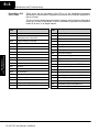
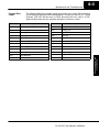
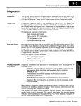
Maintenance and
Troubleshooting
18
In This Chapter. . . .
— Hardware System Maintenance
— Diagnostics
— CPU Indicators
— Communications Problems
— I/O Point Troubleshooting
— Noise Troubleshooting
— Machine Startup and Program Troubleshooting
8--2
Maintenance and Troubleshooting
Hardware System Maintenance
Standard
Maintenance
Maintenance
and Troubleshooting
Maintenabce
and Troubleshooting
Diagnostics
No regular or preventative maintenance is required for this product (there are no
internal batteries); however, a routine maintenance check (about every one or two
months) of your PLC and control system is good practice, and should include the
following items:
S Air Temperature -- Check the air temperature in the control cabinet, so
the operating temperature range of any component is not exceeded.
S Air Filter -- If the control cabinet has an air filter, clean or replace it
periodically as required.
S Fuses or breakers -- verify that all fuses and breakers are intact.
S DL105 Air Vents -- check that all air vents are clear. If the exterior case
needs cleaning, disconnect the input power, and carefully wipe the case
using a damp cloth. Do not let water enter the case through the air vents
and do not use strong detergents because this may discolor the case.
Diagnostics
Your DL105 Micro PLC performs many pre-defined diagnostic routines with every
CPU scan. The diagnostics can detect various errors or failures in the PLC. The two
primary error classes are fatal and non-fatal.
Fatal Errors
Fatal errors are errors which may cause the system to function improperly, perhaps
introducing a safety problem. The CPU will automatically switch to Program Mode if
it is in Run Mode. (Remember, in Program Mode all outputs are turned off.) If the fatal
error is detected while the CPU is in Program Mode, the CPU will not allow you to
transition to Run Mode until the error has been corrected.
Some examples of fatal errors are:
S Power supply failure
S Parity error or CPU malfunction
S Particular programming errors
Non-fatal Errors
Non-fatal errors are errors that need your attention, but should not cause improper
operation. They do not cause or prevent any mode transitions of the CPU. The
application program can use special relay contacts to detect non-fatal errors, and
even take the system to an orderly shutdown or switch the CPU to Program Mode if
desired. An example of a non-fatal error is:
S Particular programming errors
Finding Diagnostic The programming devices will notify you of an error if one occurs while online.
Information
S DirectSOFT provides the error number and an error message.
S The handheld programmer displays error numbers and short
descriptions of the error.
Appendix B has a complete list of error messages in order by error number.
Many error messages point to supplemental V-memory locations which contain
related information. Special relays (SP contacts) also provide error indications.
DL105 PLC User Manual, 3rd Edition
Maintenance and Troubleshooting
8--3
The following table names the specific memory locations that correspond to certain
types of error messages.
V-memory Error
Code Locations
Error Class
Error Category
Diagnostic
V-memory
User-Defined
Error code used with FAULT instruction
V7751
System Error
Fatal Error code
V7755
Major Error code
V7756
Minor Error code
V7757
Address where syntax error occurs
V7763
Grammatical
Error Code found during syntax check V7764
CPU Scan
Number of scans since last Program
to Run Mode transition
V7765
Current scan time (ms)
V7775
Minimum scan time (ms)
V7776
Maximum scan time (ms)
V7777
Accumulator Status Relays
SP12
Terminal Run mode
SP60
Acc. is less than value
SP16
Terminal Program mode
SP61
Acc. is equal to value
SP20
STOP instruction was executed
SP62
Acc. is greater than value
SP22
Interrupt enabled
SP63
Acc. result is zero
System Monitoring Relays
SP64
Half borrow occurred
SP40
Critical error
SP65
Borrow occurred
SP41
Non-critical error
SP66
Half carry occurred
SP44
Program memory error
SP67
Carry occurred
SP50
Fault instruction was executed
SP70
Result is negative (sign)
SP51
Watchdog timeout
SP71
Pointer reference error
SP52
Syntax error
SP73
Overflow
SP53
Cannot solve the logic
SP75
Data is not in BCD
SP76
Load zero
DL105 PLC User Manual, 3rd Edition
Maintenance
and Troubleshooting
CPU Status Relays
Maintenance
and Troubleshooting
Special Relays (SP) The special relay table also includes status indicators which can indicate errors. For
Corresponding to a more detailed description of each of these special relays refer to Appendix D.
Error Codes
8--4
Maintenance and Troubleshooting
Maintenance
and Troubleshooting
Maintenabce
and Troubleshooting
DL105 Micro PLC
Error Codes
These errors can be generated by the CPU or by the Handheld Programmer,
depending on the actual error. Appendix B provides a more complete description of
the error codes.
The errors can be detected at various times. However, most of them are detected at
power-up, on entry to Run Mode, or when a Handheld Programmer key sequence
results in an error or an illegal request.
Error
Code
Description
Error
Code
Description
E003
Software time-out
E526
Unit is offline
E004
Invalid instruction
(RAM parity error in the CPU)
E527
Unit is online
E099
Program memory exceeded
E528
CPU mode
E151
Invalid command
E540
CPU locked
E155
RAM failure
E541
Wrong password
E210
Power fault
E542
Password reset
E312
Communications error 2
E601
Memory full
E313
Communications error 3
E602
Instruction missing
E316
Communications error 6
E604
Reference missing
E320
Time out
E620
Out of memory
E321
Communications error
E621
EEPROM Memory not blank
E501
Bad entry
E622
No Handheld Programmer EEPROM
E502
Bad address
E624
V memory only
E503
Bad command
E625
Program only
E504
Bad reference / value
E627
Bad write operation
E505
Invalid instruction
E628
Memory type error (should be EEPROM)
E506
Invalid operation
E640
Mis-compare
E520
Bad operation -- CPU in Run
E650
Handheld Programmer system error
E524
Bad operation -- CPU in Program
E651
Handheld Programmer ROM error
E652
Handheld Programmer RAM error
DL105 PLC User Manual, 3rd Edition
Maintenance and Troubleshooting
Program Error
Codes
8--5
The following table lists program syntax and runtime error codes. Error detection
occurs during a Program-to-Run mode transition, or when you use AUX 21 -- Check
Program. The CPU will also turn on SP52 and store the error code in V7755.
Appendix B provides a more complete description of the error codes.
Error Code
Description
Error Code
Description
No Program in CPU
E452
X input used as output coil
E401
Missing END statement
E453
Missing T/C
E402
Missing LBL
E454
Bad TMRA
E406
Missing IRT
E455
Bad CNT
E421
Duplicate stage reference
E456
Bad SR
E422
Duplicate SBR/LBL reference
E461
Stack Overflow
E431
Invalid ISG/SG address
E462
Stack Underflow
E436
Invalid INT address
E463
Logic Error
E438
Invalid IRT address
E464
Missing Circuit
E440
Invalid Data Address
E471
Duplicate coil reference
E441
ACON/NCON
E472
Duplicate TMR reference
E451
Bad MLS/MLR
E473
Duplicate CNT reference
Maintenance
and Troubleshooting
E4**
Maintenance
and Troubleshooting
DL105 PLC User Manual, 3rd Edition
8--6
Maintenance and Troubleshooting
CPU Indicators
The DL105 Micro PLCs have indicators on the
front to help you diagnose problems with the
system. In normal runtime operation only the RUN
and PWR indicators are on. The table below is a
quick reference to potential problems.
Indicator Status Potential Problems
PWR (LED off)
1. System voltage incorrect
2. PLC power supply faulty
RUN (LED off)
1. CPU programming error
2. (CPU in program mode)
CPU (LED on)
1. Electrical noise interference
2. Internal CPU defective
Maintenance
and Troubleshooting
Maintenabce
and Troubleshooting
PWR Indicator
Run, Power, CPU
Indicators
In general there are three reasons for the CPU power status LED (PWR) to be OFF:
1. Power to the unit is incorrect or is not applied.
2. PLC power supply is faulty.
3. Other component(s) have the power supply shut down.
If the voltage to the power supply is not correct, the PLC may not operate properly or
may not operate at all. Use the following guidelines to correct the problem.
WARNING: To minimize the risk of electrical shock, always disconnect the
system power before inspecting the physical wiring.
1. First, disconnect the external power.
2. Verify that all external circuit breakers or fuses are still intact.
3. Check all incoming wiring for loose connections. If you’re using a separate
termination block, check those connections for accuracy and integrity.
4. If the connections are acceptable, reconnect the system power and verify
the voltage at the DL105 power input is within specification. If the voltage is
not correct shut down the system and correct the problem.
5. If all wiring is connected correctly and the incoming power is within the
specifications, the PLC internal supply may be faulty.
The best way to check for a faulty PLC is to substitute a known good one to see if this
corrects the problem. The removable connectors on the DL105 make this relatively
easy. If there has been a major power surge, it is possible the PLC internal power
supply has been damaged. If you suspect this is the cause of the power supply
damage, consider installing an AC line conditioner to attenuate damaging voltage
spikes in the future.
DL105 PLC User Manual, 3rd Edition
Maintenance and Troubleshooting
8--7
RUN Indicator
If the CPU will not enter the Run mode (the RUN indicator is off), the problem is
usually in the application program, unless the CPU has a fatal error. If a fatal error
has occurred, the CPU LED should be on. (You can use a programming device to
determine the cause of the error.)
Both of the programming devices, Handheld Programmer and DirectSOFT, will
return an error message describing the problem. Depending on the error, there may
also be an AUX function you can use to help diagnose the problem. The most
common programming error is “Missing END Statement”. All application programs
require an END statement for proper termination. A complete list of error codes can
be found in Appendix B.
CPU Indicator
If the CPU indicator is on, a fatal error has occurred in the CPU. Generally, this is not
a programming problem but an actual hardware failure. You can power cycle the
system to clear the error. If the error clears, you should monitor the system and
determine what caused the problem. You will find this problem is sometimes caused
by high frequency electrical noise introduced into the CPU from an outside source.
Check your system grounding and install electrical noise filters if the grounding is
suspected. If power cycling the system does not reset the error, or if the problem
returns, you should replace the CPU.
If you cannot establish communications with the CPU, check these items.
S
S
S
S
For problems in communicating with DirectSOFT on a personal computer, refer to
the DirectSOFT manual. It includes a troubleshooting section that can help you
diagnose PC problems in communications port setup, address or interrupt conflicts,
etc.
DL105 PLC User Manual, 3rd Edition
Maintenance
and Troubleshooting
S
S
S
S
The cable is disconnected.
The cable has a broken wire or has been wired incorrectly.
The cable is improperly terminated or grounded.
The device connected is not operating at the correct baud rate (9600
baud).
The device connected to the port is sending data incorrectly.
A grounding difference exists between the two devices.
Electrical noise is causing intermittent errors.
The PLC has a bad communication port and should be replaced.
Maintenance
and Troubleshooting
Communications Problems
8--8
Maintenance and Troubleshooting
Maintenance
and Troubleshooting
Maintenabce
and Troubleshooting
I/O Point Troubleshooting
Possible Causes
If you suspect an I/O error, there are several things that could be causing the
problem.
S High-Speed I/O configuration error
S A blown fuse in your machine or panel (the DL105 does not have
internal I/O fuses)
S A loose terminal block
S The auxiliary 24 VDC supply has failed
S The Input or Output Circuit has failed
Some Quick Steps
When troubleshooting the DL105 Micro PLCs there are a few facts you should be
aware of. These facts may assist you in quickly correcting an I/O problem.
S HSIO configuration errors are commonly mistaken for I/O point failure
during program development. If the I/O point in question is in X0--X3, or
Y0--Y2, check all parameter locations listed in Chapter 3 that apply to
the HSIO mode you have selected.
S The output circuits cannot detect shorted or open output points. If you
suspect one or more faulty points, measure the voltage drop from the
common to the suspect point. Remember when using a Digital Volt
Meter, leakage current from an output device such as a triac or a
transistor must be considered. A point which is off may appear to be on
if no load is connected the point.
S The I/O point status indicators are logic-side indicators. This means the
LED which indicates the on or off status reflects the status of the point
with respect to the CPU. On an output point the status indicators could
be operating normally while the actual output device (transistor, triac
etc.) could be damaged. With an input point, if the indicator LED is on
the input circuitry is probably operating properly. Verify the LED goes off
when the input signal is removed.
S Leakage current can be a problem when connecting field devices to an
I/O point. False input signals can be generated when the leakage
current of an output device is great enough to turn on the connected
input device. To correct this install a resistor in parallel with the input or
output of the circuit. The value of this resistor will depend on the amount
of leakage current and the voltage applied but usually a 10K to 20KΩ
resistor will work. Verify the wattage rating of the resistor is correct for
your application.
S Because of the removable terminal blocks on the DL105, the easiest
method to determine if an I/O circuit has failed is to replace the unit if
you have a spare. However, if you suspect a field device is defective,
that device may cause the same failure in the replacement PLC as well.
As a point of caution, you may want to check devices or power supplies
connected to the failed I/O circuit before replacing the unit with a spare.
DL105 PLC User Manual, 3rd Edition
Maintenance and Troubleshooting
Testing Output
Points
8--9
Output points can be set on or off in the DL105 series CPUs. If you want to do an I/O
check out independent of the application program, follow the procedure below:
Step
Action
1
Use a handheld programmer or DirectSOFT32 to communicate online
to the PLC.
2
Change to Program Mode.
3
Go to address 0.
4
Insert an “END” statement at address 0. (This will cause program
execution to occur only at address 0 and prevent the application program from turning the I/O points on or off).
5
Change to Run Mode.
6
Use the programming device to set (turn) on or off the points you wish
to test.
7
When you finish testing I/O points delete the “END” statement at
address 0.
Handheld
Programmer
Keystrokes Used
to Test an Output
Point
END
X0
X2
X1
X3
X5
X7
Y2
X4
END
From a clear display, use the following keystrokes
STAT
16P STATUS
BIT REF
X
ENT
Use the PREV or NEXT keys to select the Y data type
NEXT
A
0
Y
ENT
Use arrow keys to select point, then use
ON and OFF to change the status
SHFT
ON
INS
10
Y
0
Y2 is now on
Y
10
Y
0
DL105 PLC User Manual, 3rd Edition
Maintenance
and Troubleshooting
Insert an END statement
at the beginning of the
program. This disables
the remainder of the
program.
Maintenance
and Troubleshooting
WARNING: Depending on your application, forcing I/O points may cause
unpredictable machine operation that can result in a risk of personal injury or
equipment damage. Make sure you have taken all appropriate safety
precautions prior to testing any I/O points.
8--10
Maintenance and Troubleshooting
Maintenance
and Troubleshooting
Maintenabce
and Troubleshooting
Noise Troubleshooting
Electrical Noise
Problems
Noise is one of the most difficult problems to diagnose. Electrical noise can enter a
system in many different ways and they fall into one of two categories, conducted or
radiated. It may be difficult to determine how the noise is entering the system but the
corrective actions for either of the types of noise problems are similar.
S Conducted noise is when the electrical interference is introduced into
the system by way of a attached wire, panel connection ,etc. It may
enter through an I/O circuit, a power supply connection, the
communication ground connection, or the chassis ground connection.
S Radiated noise is when the electrical interference is introduced into the
system without a direct electrical connection, much in the same manner
as radio waves.
Reducing
Electrical Noise
While electrical noise cannot be eliminated it can be reduced to a level that will not
affect the system.
S Most noise problems result from improper grounding of the system. A
good earth ground can be the single most effective way to correct noise
problems. If a ground is not available, install a ground rod as close to
the system as possible. Ensure all ground wires are single point
grounds and are not daisy chained from one device to another. Ground
metal enclosures around the system. A loose wire can act as a large
antenna, introducing noise into the system. Therefore, tighten all
connections in your system. Loose ground wires are more susceptible to
noise than the other wires in your system. Review Chapter 2 Installation,
Wiring, and Specifications if you have questions regarding how to
ground your system.
S Electrical noise can enter the system through the power source for the
PLC and I/O circuits. Installing an isolation transformer for all AC
sources can correct this problem. DC sources should be well-grounded
good quality supplies.
S Separate input wiring from output wiring. Never run low-voltage I/O
wiring close to high voltage wiring.
DL105 PLC User Manual, 3rd Edition
Maintenance and Troubleshooting
8--11
Machine Startup and Program Troubleshooting
The DL105 Micro PLCs provide several features that can help you debug your
program before and during machine startup. This section discusses the following
topics which can be very helpful.
S Program Syntax Check
S Duplicate Reference Check
S Special Instructions
S Run Time Edits
S Forcing I/O Points
Syntax Check
Even though the Handheld Programmer and DirectSOFT provide error checking
during program entry, you may want to check a program that has been modified.
Both programming devices offer a way to check the program syntax. For example,
you can use AUX 21, CHECK PROGRAM to check the program syntax from a
Handheld Programmer, or you can use the PLC Diagnostics menu option within
DirectSOFT. This check will find a wide variety of programming errors. The following
example shows how to use the syntax check with a Handheld Programmer.
CLR
C
2
B
1
AUX
AUX 21 CHECK PRO
1:SYN 2:DUP REF
ENT
Select syntax check (default selection)
ENT
(You may not get the busy display
if the program is not very long.)
BUSY
Error Display (example)
$00050 E401
MISSING END
(shows location in question)
Syntax OK display
NO SYNTAX ERROR
?
See the Error Codes Section for a complete listing of programming error codes. If
you get an error, just press CLR and the Handheld will display the instruction where
the error occurred. Correct the problem and continue running the Syntax check until
the NO SYNTAX ERROR message appears.
DL105 PLC User Manual, 3rd Edition
Maintenance
and Troubleshooting
One of two displays will appear
Maintenance
and Troubleshooting
Use AUX 21 to perform syntax check
8--12
Maintenance and Troubleshooting
Special
Instructions
There are several instructions that can be used to help you debug your program
during machine startup operations.
S END
S PAUSE
S STOP
END Instruction: If you need a way to quickly disable part of the program, just insert
an END statement prior to the portion that should be disabled. When the CPU
encounters the END statement, it assumes that is the end of the program. The
following diagram shows an example.
New END disables X10 and Y1
Normal Program
X0
X2
X1
X3
Y0
X4
X0
X2
X1
X3
Y0
X4
Y1
X10
END
Y1
X10
Maintenabce
and Troubleshooting
END
END
PAUSE Instruction: This instruction provides a quick way to allow the inputs (or
other logic) to operate while disabling selected outputs. The output image register is
still updated, but the output circuits are not. For example, you could make this
conditional by adding an input contact or CR to control the instruction with a switch or
a programming device. Or, you could just add the instruction without any conditions
so the selected outputs would be disabled at all times.
PAUSE disables Y0 and Y1
Maintenance
and Troubleshooting
Normal Program
X0
X2
X1
X3
Y0
Y0 -- Y1
PAUSE
X10
X4
Y1
X0
X2
X1
X3
X10
Y0
X4
Y1
END
END
STOP Instruction: Sometimes during machine startup you need a way to quickly
turn off all the outputs and return to Program Mode. You can use the STOP
instruction. When this instruction is executed the CPU automatically exits Run Mode
and enters Program Mode. Remember, all outputs are turned off during Program
Mode. The following diagram shows an example of a condition that returns the CPU
to Program Mode.
DL105 PLC User Manual, 3rd Edition
Maintenance and Troubleshooting
STOP puts CPU in Program Mode
Normal Program
X0
X2
X1
X3
8--13
Y0
X10
STOP
X4
Y1
X5
X0
X2
X1
X3
Y0
X4
X5
Y1
END
END
Duplicate
Reference Check
Use AUX 21 to perform syntax check
CLR
C
2
B
1
AUX
AUX 21 CHECK PRO
1:SYN 2:DUP REF
ENT
Select duplicate reference check
ENT
BUSY
One of two displays will appear
Error Display (example)
(shows location in question)
Syntax OK display
$00024 E471
DUP COIL REF
NO DUP REFS
?
If you get an error, just press CLR and the Handheld will display the instruction where
the error occurred. Correct the problem and continue running the Duplicate
Reference check until no duplicate references are found.
NOTE: You can use the same coil in more than one location, especially in programs
containing Stage instructions and / or OROUT instructions. The Duplicate
Reference check will find occurrences, even though they are acceptable.
DL105 PLC User Manual, 3rd Edition
Maintenance
and Troubleshooting
(You may not get the busy
display if the program is not
very long.)
Maintenance
and Troubleshooting
In the example shown above, you could trigger X10 which would execute the STOP
instruction. The CPU would enter Program Mode and all outputs would be turned off.
You can also check for multiple uses of the same output coil. Both programming
devices offer a way to check for this condition.. For example, you can AUX 21,
CHECK PROGRAM to check for duplicate references from a Handheld
Programmer, or you can use the PLC Diagnostics menu option within DirectSOFT.
The following example shows how to perform the duplicate reference check with a
Handheld Programmer.
8--14
Maintenance and Troubleshooting
Run Time Edits
The DL105 Micro PLC allows you to make changes to the application program
during Run Mode. These edits are not “bumpless.” Instead, CPU scan is
momentarily interrupted (and the outputs are maintained in their current state) until
the program change is complete. This means if the output is off, it will remain off until
the program change is complete. If the output is on, it will remain on.
Maintenance
and Troubleshooting
Maintenabce
and Troubleshooting
WARNING: Only authorized personnel fully familiar with all aspects of the
application should make changes to the program. Changes during Run Mode
become effective immediately. Make sure you thoroughly consider the impact
of any changes to minimize the risk of personal injury or damage to
equipment. There are some important operational changes during Run Time
Edits.
1. If there is a syntax error in the new instruction, the CPU will not enter the
Run Mode.
2. If you delete an output coil reference and the output was on at the time, the
output will remain on until it is forced off with a programming device.
3. Input point changes are not acknowledged during Run Time Edits. So, if
you’re using a high-speed operation and a critical input comes on, the CPU
may not see the change.
Not all instructions can be edited during a Run Time Edit session. The following list
shows the instructions that can be edited.
Mnemonic
Description
Mnemonic
Description
TMR
Timer
OR, ORN
TMRF
Fast timer
Or greater than or equal
Or less than
TMRA
Accumulating timer
LD
Load data (constant)
TMRAF
Accumulating fast timer
LDD
Load data double (constant)
CNT
Counter
ADDD
Add data double (constant)
UDC
Up / Down counter
SUBD
Subtract data double (constant)
SGCNT
Stage counter
MUL
Multiply (constant)
STR, STRN
Store, Store not
DIV
Divide (constant)
AND, ANDN
And, And not
CMPD
Compare accumulator (constant)
OR, ORN
Or, Or not
ANDD
And accumulator (constant)
STRE, STRNE
Store equal, Store not equal
ORD
Or accumulator (constant)
ANDE, ANDNE
And equal, And not equal
XORD
Exclusive or accumulator (constant)
ORE, ORNE
Or equal, Or not equal
LDF
Load discrete points to accumulator
STR, STRN
Store greater than or equal
Store less than
OUTF
Output accumulator to discrete points
SHFR
Shift accumulator right
AND, ANDN
And greater than or equal
And less than
SHFL
Shift accumulator left
NCON
Numeric constant
DL105 PLC User Manual, 3rd Edition
Maintenance and Troubleshooting
We’ll use the program logic shown to describe how this process works. In the example, we’ll change X0 to C10. Note, the
example assumes you have already
placed the CPU in Run Mode.
X0
X1
8--15
Y0
OUT
C0
Use the MODE key to select Run Time Edits
MODE
NEXT
NEXT
*MODE CHANGE*
RUN TIME EDIT?
ENT
Press ENT to confirm the Run Time Edits
ENT
(Note, the RUN LED on the D2--HPP
Handheld starts flashing to indicate
Run Time Edits are enabled.)
*MODE CHANGE*
RUNTIME EDITS
Find the instruction you want to change (X0)
X
SET
A
0
SHFT
FD REF
FIND
$00000 STR X0
Press the arrow key to move to the X. Then enter the new contact (C10).
SHFT
C
2
B
1
A
0
ENT
RUNTIME EDIT?
STR C10
ENT
(Note, once you press ENT, the next
address is displayed.
OR C0
DL105 PLC User Manual, 3rd Edition
Maintenance
and Troubleshooting
Press ENT to confirm the change
Maintenance
and Troubleshooting
SHFT
8--16
Maintenance and Troubleshooting
Forcing I/O Points
There are many times, especially during machine startup and troubleshooting, that
you need the capability to force an I/O point to be either on or off. Before you use a
programming device to force any data type it is important you understand how the
DL105 CPUs process the forcing requests.
WARNING: Only authorized personnel fully familiar with the application
should make program changes. Do thoroughly consider the impact of any
changes to minimize the risk of personal injury or damage to equipment.
Bit Forcing — Bit forcing temporarily changes the status of a discrete bit. For
example, you may want to force an input on even though the program has turned it
off. This allows you to change the point status stored in the image register. The
forced value will be valid until the CPU writes to the image register location during the
next scan. This is useful you just need to force a bit on to trigger another event.
The following diagrams show a brief
example of how you could use the
D2--HPP Handheld Programmer to force
an I/O point. The example assumes you
have already placed the CPU into Run
Mode.
Y0
OUT
C0
From a clear display, use the following keystrokes
Maintenabce
and Troubleshooting
Maintenance
and Troubleshooting
X0
STAT
16P STATUS
BIT REF
X
ENT
Use the PREV or NEXT keys to select the Y data type. (Once the Y
appears, press 0 to start at Y0.)
NEXT
A
0
Y
ENT
Use arrow keys to select point, then use
ON and OFF to change the status
SHFT
Bit Forcing with
Direct Access
ON
INS
From a blank display, use the following
keystrokes to force Y7 ON
SHFT
Y
MLS
H
7
SHFT
ON
INS
From a blank display, use the following
keystrokes to force Y7 OFF
SHFT
Y
MLS
DL105 PLC User Manual, 3rd Edition
H
7
SHFT
OFF
DEL
10
Y
0
Y
0
Y2 is now on
Y
10
Solid fill indicates point is on.
BIT FORCE
Y7
No fill indicates point is off.
BIT FORCE
Y7