1
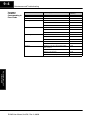
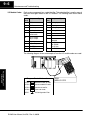
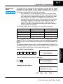
9–3
Maintenance and Troubleshooting
Diagnostics
Your DL205 system performs many pre-defined diagnostic routines with every CPU
scan. The diagnostics have been designed to detect various types of failures for the
CPU and I/O modules. There are two primary error classes, fatal and non-fatal.
Fatal Errors
Fatal errors are errors the CPU has detected that offer a risk of the system not
functioning safely or properly. If the CPU is in Run Mode when the fatal error occurs,
the CPU will switch to Program Mode. (Remember, in Program Mode all outputs are
turned off.) If the fatal error is detected while the CPU is in Program Mode, the CPU
will not enter Run Mode until the error has been corrected.
Here are some examples of fatal errors.
S Base power supply failure
S Parity error or CPU malfunction
S I/O configuration errors
S Certain programming errors
Non-fatal Errors
Non-fatal errors are errors that are flagged by the CPU as requiring attention. They
can neither cause the CPU to change from Run Mode to Program Mode, nor do they
prevent the CPU from entering Run Mode. There are special relays the application
program can use to detect if a non-fatal error has occurred. The application program
can then be used to take the system to an orderly shutdown or to switch the CPU to
Program Mode if necessary.
Some examples of non-fatal errors are:
S Backup battery voltage low
S All I/O module errors
S Certain programming errors
Maintenance
and Troubleshooting
Finding Diagnostic Diagnostic information can be found in several places with varying levels of
message detail.
Information
S The CPU automatically logs error codes and any FAULT messages into
two separate tables which can be viewed with the Handheld or
DirectSOFT32.
S The handheld programmer displays error numbers and short
descriptions of the error.
S DirectSOFT32 provides the error number and an error message.
S Appendix B in this manual has a complete list of error messages sorted
by error number.
Maintenance
and Troubleshooting
Diagnostics
Many of these messages point to supplemental memory locations which can be
referenced for additional related information. These memory references are in the
form of V-memory and SPs (special relays).
The following two tables name the specific memory locations that correspond to
certain types of error messages. The special relay table also includes status
indicators which can be used in programming. For a more detailed description of
each of these special relays refer to Appendix D.
DL205 User Manual, 3rd Ed., Rev. A, 08/03
9–4
Maintenance and Troubleshooting
V-memory
Locations
Corresponding to
Error Codes
Error Class
Error Category
Diagnostic
V-memory
Battery Voltage (DL240 only)
Shows battery voltage to tenths (32 is 3.2V)
V7746
User-Defined
Error code used with FAULT instruction
V7751
I/O Configuration
Correct module ID code
V7752
Incorrect module ID code
V7753
Base and Slot number where error occurs
V7754
Fatal Error code
V7755
Major Error code
V7756
Minor Error code
V7757
Base and slot number where error occurs
V7760
Always holds a “0”
V7761
Error code
V7762
Address where syntax error occurs
V7763
Error Code found during syntax check
V7764
Number of scans since last Program to Run
Mode transition
V7765
Current scan time (ms)
V7775
Minimum scan time (ms)
V7776
Maximum scan time (ms)
V7777
Module Diagnostic
Grammatical
CPU Scan
Maintenance
and Troubleshooting
Maintenance
and Troubleshooting
System Error
DL205 User Manual, 3rd Ed., Rev. A, 08/03
9–5
Maintenance and Troubleshooting
Special Relays (SP)
Corresponding to
Error Codes
Accumulator Status Relays
SP0
On first scan only
SP60
Acc. is less than value
SP1
Always ON
SP61
Acc. is equal to value
SP2
Always OFF
SP62
Acc. is greater than value
SP3
1 minute clock
SP63
Acc. result is zero
SP4
1 second clock
SP64
Half borrow occurred
SP5
100 millisecond clock
SP65
Borrow occurred
SP6
50 millisecond clock
SP66
Half carry occurred
SP7
On alternate scans
SP67
Carry occurred
CPU Status Relays
SP70
Result is negative (sign)
SP11
Forced run mode (DL240 only)
SP71
Pointer reference error
SP12
Terminal run mode
SP73
Overflow
SP13
Test run mode
(DL240 only)
SP75
Data is not in BCD
SP76
Load zero
SP15
Test program mode (DL240 only)
Communication Monitoring Relays
SP16
Terminal program mode
SP20
STOP instruction was executed
SP22
Interrupt enabled
System Monitoring Relays
Critical error
SP41
Non-critical error
SP43
Battery low
SP44
Program memory error
SP45
I/O error
SP46
Communications error
SP47
I/O configuration error
SP50
Fault instruction was executed
SP51
Watchdog timeout
SP52
Syntax error
SP53
Cannot solve the logic
SP54
Intelligent module communication error
CPU is communicating with another
device
SP116
DL250–1 / DL260
Port 2 is communicating with another
device
SP117
Communication error on Port 2
(DL250–1 / DL260 only)
SP120
Module busy, Slot 0
SP121
Communication error Slot 0
SP122
Module busy, Slot 1
SP123
Communication error Slot 1
SP124
Module busy, Slot 2
SP125
Communication error Slot 2
SP126
Module busy, Slot 3
SP127
Communication error Slot 3
SP130
Module busy, Slot 4
SP131
Communication error Slot 4
SP132
Module busy, Slot 5
SP133
Communication error Slot 5
SP134
Module busy, Slot 6
SP135
Communication error Slot 6
SP136
Module busy, Slot 7
SP137
Communication error Slot 7
Maintenance
and Troubleshooting
SP40
SP116
DL230/DL240
Maintenance
and Troubleshooting
Startup and Real-time Relays
DL205 User Manual, 3rd Ed., Rev. A, 08/03
9–6
Maintenance and Troubleshooting
Maintenance
and Troubleshooting
I/O Module Codes
Each system component has a code identifier. This code identifier is used in some of
the error messages related to the I/O modules. The following table shows these
codes.
Code
(Hex)
Component Type
Code
(Hex)
Component Type
04
CPU
36
Analog Input
03
I/O Base
2B
16 pt. Input
20
8 pt. Output
37
Analog Output
21
8 pt. Input
3D
Analog I/O Combo
24
4input/output
combination
4A
Counter Interface
28
12 pt. Output,
16 pt. Output
7F
Abnormal
FF
No module
detected
EE
D2–DCM
H2–ECOM
F2–CP128
BE
D2–RMSM
3F
32 pt. Input
30
32 pt. Output
52
H2–ERM
51
H2–CTRIO
Maintenance
and Troubleshooting
The following diagram shows an example of how the I/O module codes are used:
Program Control Information
V7752 0020 Desired module ID code
V7753 0026 Current module ID code
V7754 0002 Location of conflict
V7755 0252 Fatal error code
SP47
I/O Configuration Error
DL205 User Manual, 3rd Ed., Rev. A, 08/03
E252
NEW I/O CFG
9–7
Maintenance and Troubleshooting
Error Message
Tables
5
230
4 4
4
240 250–1 260
Date
Time
Message
1993–05–26
08:41:51:11
*Conveyor–2 stopped
1993–04–30
17:01:11:56
* Conveyor–1 stopped
1993–04–30
17:01:11:12
* Limit SW1 failed
1993–04–28
03:25:14:31
* Saw Jam Detect
Maintenance
and Troubleshooting
The DL240 CPU will automatically log any system error codes and any custom
messages you have created in your application program with the FAULT
instructions. The CPU logs the error code, the date, and the time the error occurred.
There are two separate tables that store this information.
S Error Code Table – the system logs up to 32 errors in the table. When
an error occurs, the errors already in the table are pushed down and the
most recent error is loaded into the top position. If the table is full when
an error occurs, the oldest error is pushed (erased) from the table.
S Message Table – the system logs up to 16 messages in this table. When
a message is triggered, the messages already stored in the table are
pushed down and the most recent message is loaded into the top
position. If the table is full when an error occurs, the oldest message is
pushed (erased) from the table.
The following diagram shows an example of an error table for messages.
You can access the error code table and the message table through
DirectSOFT32’s PLC Diagnostic sub-menus or from the Handheld Programmer.
Details on how to access these logs are provided in the DL205 DirectSOFT32
manual.
The following examples show you how to use the Handheld and AUX Function 5C to
show the error codes. The most recent error or message is always displayed. You
can use the PREV and NXT keys to scroll through the messages.
CLR
F
5
SHFT
C
2
AUX
AUX 5C HISTORY D
ERROR/MESAGE
ENT
Use the arrow key to select Errors or Messages
AUX 5C HISTORY D
ERROR/MESAGE
ENT
Maintenance
and Troubleshooting
Use AUX 5C to view the tables
Example of an error display
E252NEW I/O CFG
93/09/21 10:11:15
Year
Month
Day
Time
DL205 User Manual, 3rd Ed., Rev. A, 08/03
9–8
Maintenance and Troubleshooting
System Error
Codes
5
230
4 4
4
240 250–1 260
The System error log contains 32 of the most recent errors that have been detected.
The errors that are trapped in the error log are a subset of all the error messages
which the DL205 systems generate. These errors can be generated by the CPU or
by the Handheld Programmer, depending on the actual error. Appendix B provides a
more complete description of the error codes.
Maintenance
and Troubleshooting
Maintenance
and Troubleshooting
The errors can be detected at various times. However, most of them are detected at
power-up, on entry to Run Mode, or when a Handheld Programmer key sequence
results in an error or an illegal request.
Error
Code
Description
Error
Code
Description
E003
Software time-out
E506
Invalid operation
E004
Invalid instruction
(RAM parity error in the CPU)
E520
Bad operation – CPU in Run
E041
CPU battery low
E521
Bad operation – CPU in Test Run
E043
Memory cartridge battery low
E523
Bad operation – CPU in Test Program
E099
Program memory exceeded
E524
Bad operation – CPU in Program
E101
CPU memory cartridge missing
E525
Mode switch not in TERM
E104
Write fail
E526
Unit is offline
E151
Invalid command
E527
Unit is online
E155
RAM failure
E528
CPU mode
E201
Terminal block missing
E540
CPU locked
E202
Missing I/O module
E541
Wrong password
E203
Blown fuse
E542
Password reset
E206
User 24V power supply failure
E601
Memory full
E210
Power fault
E602
Instruction missing
E250
Communication failure in the I/O chain
E604
Reference missing
E251
I/O parity error
E610
Bad I/O type
E252
New I/O configuration
E611
Bad Communications ID
E262
I/O out of range
E620
Out of memory
E312
Communications error 2
E313
Communications error 3
E621
EEPROM Memory not blank
E316
Communications error 6
E622
No Handheld Programmer EEPROM
E320
Time out
E624
V memory only
E321
Communications error
E625
Program only
E499
Invalid Text entry for Print Instruction
E627
Bad write operation
E501
Bad entry
E628
Memory type error (should be EEPROM)
E502
Bad address
E640
Miscompare
E503
Bad command
E650
Handheld Programmer system error
E504
Bad reference / value
E651
Handheld Programmer ROM error
E505
Invalid instruction
E652
Handheld Programmer RAM error
DL205 User Manual, 3rd Ed., Rev. A, 08/03
9–9
Maintenance and Troubleshooting
Program Error
Codes
The following list shows the errors that can occur when there are problems with the
program. These errors will be detected when you try to place the CPU into Run
Mode, or, when you use AUX 21 – Check Program. The CPU will also turn on SP52
and store the error code in V7755. Appendix B provides a more complete description
of the error codes.
Error Code
Description
Error Code
Description
E461
Stack Overflow
E401
Missing END statement
E462
Stack Underflow
E402
Missing LBL
E463
Logic Error
E403
Missing RET
E464
Missing Circuit
E404
Missing FOR
E471
Duplicate coil reference
E405
Missing NEXT
E472
Duplicate TMR reference
E406
Missing IRT
E473
Duplicate CNT reference
E412
SBR/LBL >64
E480
CV position error
E413
FOR/NEXT >64
E481
CV not connected
E421
Duplicate stage reference
E482
CV exceeded
E422
Duplicate SBR/LBL reference
E483
CVJMP placement error
E423
Nested loops
E484
No CV
E431
Invalid ISG/SG address
E485
No CVJMP
E432
Invalid jump (GOTO) address
E486
BCALL placement error
E433
Invalid SBR address
E487
No Block defined
E434
Invalid RTC address
E488
Block position error
E435
Invalid RT address
E489
Block CR identifier error
E436
Invalid INT address
E490
No Block stage
E437
Invalid IRTC address
E491
ISG position error
E438
Invalid IRT address
E492
BEND position error
E440
Invalid Data Address
E493
BEND I error
E441
ACON/NCON
E494
No BEND
E451
Bad MLS/MLR
E452
X input used as output coil
E453
Missing T/C
E454
Bad TMRA
E455
Bad CNT
E456
Bad SR
Maintenance
and Troubleshooting
No Program in CPU
Maintenance
and Troubleshooting
E4**
DL205 User Manual, 3rd Ed., Rev. A, 08/03