1
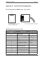
X3208a User’s Manual
Version 2.1
1 / 62
X3208a User’s Manual
Version 2.1
XAVi Technologies Corporation
Tel: +886-2-2995-7953
9F, No. 129, Hsing Te Road, Sanchung City,
Taipei Hsien 241,
Taiwan (R.O.C.)
Copyright © 2003, XAVi Technologies Corporation
Information in this manual is subject to change without notice. No part of this manual
may be reproduced or transmitted in any form or by any means, electronic or
mechanical, including photocopying or scanning, for any purpose, without the written
permission of XAVi Technologies Corporation.
XAVi Technologies Corporation provides this documentation without warranty of any
kind, implied or expressed, including, but not limited to, the implied warranties of
merchantability and fitness for a particular purpose.
2 / 62
X3208a User’s Manual
Version 2.1
Table of Contents
Chapter 1 – Getting Started
I.
II.
III.
IV.
V.
VI.
Overview……………………………..………….…..…………….…….…. 6
Features….……………………….…………………………….………..… 7
Relevant Protocol Information….…………………………………………7
Packaging………...…………………………………………………...…… 8
Safety Guidelines…………………….……...…..….………………….…. 9
Appearance……………………………………….………..……..……… 10
Front Panel…….……………………………..………..………….……… 10
Rear Panel…….….……..…..……………………..….…………….…… 11
VII. Application…………………………………………………………………12
VIII. Hardware Installation……………………………………………….…… 14
IX. Management…………………………..…………………………………. 15
X. Default Values………………………………………...……….………….16
XI. Software Upgrade…………………………………..…………………… 18
Chapter 2 – Command Line Interface
I.
II.
Console Setup..……………...…….….……………………..……..…….17
Command Tree Structure……………………………………………….. 18
A. Main Menu Command List……………………………..……….. 20
B. Data Menu Command List………………………………….…… 20
C. FRN Menu Command List…………………………………….… 21
D. FRS Menu Command List…………………….……………..….. 22
E. LAN Menu Command List………………………………………. 22
F. Manage Menu Command List………………………….………. 22
G. R1483 Menu Command List……………………………….…… 23
H. SHDSL Menu Command List…………………………..………. 23
III. CLI Commands……...……………….…………………..……………… 24
A. Main Menu Commands………………………………………….. 26
B. Data Menu Commands………………………………………..… 31
C. FRN Menu Commands…….……………………………………. 39
D. FRS Menu Commands…………….……..…………………….. 41
E. LAN Menu Commands………………………………………….. 42
F. Manage Menu Commands…………………………..…………. 44
G. R1483 Menu Commands………………………………..……… 46
H. SHDSL Menu Commands……………………….……………… 48
3 / 62
X3208a User’s Manual
Version 2.1
Table of Contents
Appendix A – Connector Pin Assignments…..….………..……52
Appendix B – Specifications
B1. Hardware Specifications..……………………..………………………..…. 56
B2. Software Specifications……………………….………….……….…….…. 57
Appendix C– Warranties
C1. Product Warranty……………….………………………..………..……….. 58
C2. Warranty Repair…………………………………………..…………..….… 58
C3. Out-of-Warranty Repair. …………………………………..……………….59
Appendix D – Regulations
D1. FCC Part 15 Notice……………………………………..……...………….. 60
D2. IC CS-03 Notice……….……………………..…………..…………….…... 62
Contact Information………………………...……….…..….…………… 62
4 / 62
X3208a User’s Manual
Version 2.1
Revision Marks
Revision Date
Notes
V 1.0
November 16, 2002
Software: Version: N/A
V 2.0
June 11, 2003
Software Version: N/A
V 2.1
June 19, 2003
Software Version: 1.00XAF2.J8I-H08.1004FR1.7-2.74B 22/Nov/2002 11:30
5 / 62
X3208a User’s Manual
Version 2.1
Chapter 1
Getting Started
I.
Overview
Based on the ITU-T G.991.2 G.SHDSL standard, X3208a
Single-pair High-speed Digital Subscriber Line (SHDSL) product
series provides a Frame Relay and ATM interworking transport
infrastructure for Public Network WAN access, high-speed Internet
access, LAN-to-LAN connectivity, and other high-speed data access
applications. It is ideal for Network Service Providers who wish to
deliver high-speed data transmissions to their customers. The WAN
interface provides programmable symmetrical rate from 72Kbps to
2312Kbps by adapting to the DSU application. The SHDSL interface
of X3208a can be configured to interoperate with SHDSL DSLAM or
to fit Point-to-Point data transmission applications by flexible
COE/CPE configurations. The Data interface of X3208a can be
configured to connect with existing Frame Relay routers.
Note: Two Implementation Agreements (IAs) in Frame Relay forum have
been developed specifically for current frame relay users: Network
Interworking (FRF.5) and Service Interworking (FRF.8). Both solutions
protect current investments in frame relay while providing a migration
path to ATM.
6 / 62
X3208a User’s Manual
II.
Version 2.1
Features
High Speed Symmetrical Data Transmission on a Single
Twisted Copper Pair Wire.
SHDSL Line Code: PAM
Data port with multi-protocol support V.35/RS530, X.21.
Provides FRF.5 Frame Relay/ATM Network Interworking
function.
Provides FRF.8 Frame Relay/ATM PVC Service Interworking
function.
Nx64Kbps rate configurable to prolong the loop reach.
High performance, simple operation, low power consumption.
Compatible and interoperable with major Central Office side
symmetric DSL DSLAM.
Local OAM&P via RS-232 Craft port or by telnet through
auto-negotiation of 10/100BaseT port.
Provides loop-back function for easy maintenance.
III.
Relevant Protocol Information
FRF.5, Frame Relay/ATM PVC Network Interworking
Implementation Agreement
FRF.8.1, Frame Relay/ATM PVC Service Interworking
Implementation Agreement
RFC 1483, Multi-protocol Encapsulation over AAL 5 (July
1993)
RFC 1490, Multi-protocol Encapsulation over Frame Relay
Rec. Q.933, Layer 3 Signaling Specification for Frame Mode
Bearer Services
af-uni-0010.002, ATM User-Network Interface (UNI), v3.1
7 / 62
X3208a User’s Manual
IV.
Version 2.1
Packaging
This package consists of the following items:
X3208a SHDSL Router
RJ-11 Cable
RJ-45 Cable
RS-530 to V.35 Cable
RS-530 to X.21 Cable (Optional)
AC Adapter
User’s Manual CD-ROM
8 / 62
X3208a User’s Manual
V.
Version 2.1
Safety Guidelines
In order to reduce the risk of fire, electric shock and injury, please
adhere to the following safety guidelines.
Carefully follow the instructions in this manual; also follow all
instruction labels on this device.
Except for the power adapter supplied, this device should not
be connected to any other adapters.
Do not spill liquid of any kind on this device.
Do not place the unit on an unstable stand or table. This unit
may drop and become damaged.
Do not expose this unit to direct sunlight.
Do not place any hot devices close to this unit, as it may
degrade or cause damage to it.
Do not place any heavy objects on top of this unit.
Do not use liquid cleaners or aerosol cleaners. Use a soft dry
cloth for cleaning.
9 / 62
X3208a User’s Manual
VI.
Version 2.1
Appearance
Front Panel
Label
Status
Color
Description
PWR
ON
Green
Power supply is connected properly.
ON
Green
Frame sync over multi-protocol.
Blinking
Green
Transmitting data over multi-protocol.
ON
Red
Loss of signal alignment.
ON
Green
Frame sync over multi-protocol.
Blinking
Green
Receiving data over multi-protocol.
ON
Red
Loss of signal alignment.
Blinking
Green
Training with DSLAM.
ON
Green
SHDSL link is ready.
Blinking
Red
Booting up.
ON
Red
Error.
TX
RX
WAN
ALM
10 / 62
X3208a User’s Manual
Version 2.1
Rear Panel
Label
Description
PWR
DC-inlet for AC Adapter.
CONSOLE
Serial port; connect to an ASCII data terminal.
ETHERNET
RJ-45 port; connect to a PC or LAN.
V.35/RS-530
DB-25 port; connect to a multi-protocol router.
WAN
RJ-11 port; connect to the SHDSL outlet.
11 / 62
X3208a User’s Manual
VII.
Version 2.1
Application
The most common applications for SHDSL DSU are used for lease
line high-speed data transmission.
Network Interworking – Scenario 1
FR Network
FR Network
FR Network
Router
Router
X3208a
X3208a
Network Interworking – Scenario 2
FR Network
FR Network
ATM Network is not
FR “aware”
Router
X3208a
ATM Router
12 / 62
X3208a User’s Manual
Version 2.1
Service Interworking – Transparent Mode
FR Network
FR Network
ATM Network is not
FR “aware”
Router
X3208a
ATM Router
Transparent Payload Transport (No Protocol Processing)
ATM AAL5-CPCS (FR Headers NOT Preserved)
Service Interworking – Translation Mode
FR Network
FR Network
ATM Network is not
FR “aware”
Router
X3208a
ATM Router
RFC 1490/FR -- Translate Encapsulation -- RFC 1483/ATM
ATM AAL5-CPCS (FR Headers NOT Preserved)
Applications:
1. Lease line high-speed data transmission with Public Network.
2. Point-to-point high-speed data transmission for campus or
other applications.
13 / 62
X3208a User’s Manual
VIII.
Version 2.1
Hardware Installation
1. Connect one end of the RJ-11 cable into the WAN port of
X3208a, and the other end into the SHDSL wall outlet.
2. Connect one end of the V.35/X.21 cable to connect to
X3208a and the other end to a V.35/X.21 router.
3. Connect one end of the RJ-45 cable into one of the RJ-45
ports of X3208a, and the other end into your PC or LAN.
4. Plug in the AC adapter into the AC power socket, and
connect the DC jack into the PWR inlet of X3208a.
5. Use a 9-pin RS-232 cable to connect the Console cable to
the RJ-45 cable then to a PC with data terminal emulation
software (Hyper Terminal) installed, in order for local
management.
4
5
3
2
1
V.35/X.21 Router
Power Supply
PC
SHDSL Outlet
Management Terminal
14 / 62
X3208a User’s Manual
IX.
Version 2.1
Management
Console Port – use the RS-232 cable for connecting
X3208a to a console terminal or a PC running a terminal
emulation program, such as Hyper Terminal. (For further
details, See Chapter 2: Command Line Interface)
Local Ethernet Port (Telnet) – connect the Ethernet port
to your local area network or directly to a PC, “telnet”
X3208a from any workstation in the LAN. The default local
Ethernet IP address is “192.168.1.1”.
Note: As operating an SHDSL device requires technical know-how and
experience. It is recommended that only qualified technical staffs
manage X3208a. Therefore, a password authentication is required when
you enter the command line and web interface. See the Default Values
section to obtain the password.
15 / 62
X3208a User’s Manual
X.
Version 2.1
Default Values
X3208a is pre-configured with the following parameters; you may
also re-load the default parameters by typing Default in the
command line interface. (For further details, See Chapter 2:
Command Line Interface)
Password: 0000
Multi-protocol Setting
Interface: V.35
Terminal: DCE
Clock source: Internal
txdatainv -- normal
txclkinv – normal
rxdatainv – normal
rxclkinv -- normal
rts -- enable
dtr -- enable
cts -- enable
dsr --enable
dcd --enable
(Local) loopback: disable
Rate -- 2048Kbps
SHDSL
Terminal: CPE (RT) side
Rate Mode: Adaptive
Line Rate Range:
Max: 2056Kbps
Min: 72Kbps
Framer Type: Utopia
SHDSL Standard: annex B
Frame Relay Setting
FR management
- 0.no maintenance
FRF.12 segment
-0
Autostart
- false
N391 protocol
-6
User N392
-3
Network N392
-3
User N393
-4
Network N393
-4
T391 timer
- 10
T392 timer
- 16
16 / 62
X3208a User’s Manual
Version 2.1
Frame Relay Service Interworking
FUNCTION
Frs
VPI/VCI
CLASS
LLC/VCMUX
Spanning
*8/36
ubr
LLC
Disable
Pkt Filter
DLCI
Trans
DE
FECN
ANY
100
1
2
2
clpi
mux
hdr dc
Remote Management
FUNCTION
Rfc 1483
Pkt Filter
VPI/VCI
CLASS
LLC/VCMUX
Spanning
*8/35
ubr
LLC
Disable
DLCI
Trans
DE
ANY
17 / 62
FECN
clpi
mux
hdr dc
X3208a User’s Manual
XI.
Version 2.1
Software Upgrade
You may easily upgrade X3208a embedded software by obtaining
the compressed upgrade kit from the service provider then following
the steps:
Extract the ZIP file for updated firmware
Connect X3208a via the local Ethernet port or remote
ADSL link, make sure that X3208a Ethernet IP address and
your terminal are properly configured so that you can
successfully “ping” X3208a. The default local IP address is
192.168.1.1.
Under the DOS prompt, execute the command “xupgrade
<IP address of X3208a >”, for instance “xupgrade
192.168.1.1”.
This upgrading process may last as long as 60 seconds.
Then reboot X3208a with new software.
Note: Strictly maintain stable power to X3208a while upgrading its
software. If the power fails during the upgrading process, contents in the
memory could be destroyed, and the system may hang. In such as
case, you must call the dealer or system integrator for repairs.
18 / 62
X3208a User’s Manual
Version 2.1
Chapter 2
Command Line Interface
I. Console Setup
Connect the RS-232 console port to an ASCII data terminal or a
PC with Widows serial Terminal mode of VT-100 (Hyper Terminal).
To Start the Hyper-terminal, follow the steps below.
1. Start "Hyper-terminal" program
On Windows 98 or Windows NT:
Click on the Start button
Programs
Accessories
Terminal Group
Double Click “Hypertrm.exe”
Connection Name
Select Icon
Click OK
2. Select a COM port to communicate with X3208a
Choose direct to COM1 or COM2 and click on OK
3. Set Port Properties
-
-
Port Setting:
Bit per second: 9600
Data bits: 8
Stop bits: 1
Parity bits: None
Flow Control: None
Settings:
Function, arrow, and ctrl keys act as: Windows keys
Emulation: Auto-detect
Back-scroll buffer lines: 500
ASCII Setup:
Echo typed characters locally
Line delay: 0 milliseconds
Character line feeds incoming line ends: enable
19 / 62
Hyper
Enter
X3208a User’s Manual
II.
Version 2.1
Command Tree Structure
A. Main Menu Command List
Command
Description
data
Entry to Frame Relay and Multiprotocol menu
default
Set all configuration to factory setting
frn
Entry to Frame Relay and ATM Network Interworking menu
(FRF.5)
frs
Entry to Frame Relay and ATM Service Interworking
menu(FRF.8)
lan
Entry to Ethernet menu
list
List status for enabled PVC
manage
Entry to management menu
ping
Ping IP for testing purpose
quick
Quick setup
r1483
Entry to RFC1483 menu
restart
Reboot modem
save
Save and restart modem
shdsl
Entry to SHDSL menu
show
Display configuration of PVC and Ethernet
ver
Display software version
B. DATA Menu Command List
Command
Description
version
Display Frame Relay and Multiprotocol module version
default
Setting all data configuration back to factory setting
Status
Display the configuration and status of current Frame Relay
and Multiprotocol setting
enable
Activate the last updated Frame Relay and Multiprotocol
parameters
interface
Configure Multiprotocol interface mode
20 / 62
X3208a User’s Manual
Version 2.1
terminal
Configure Multiprotocol terminal mode
clock
Set multi-protocol Clock source
rate
Set internal clock rate
cts
Set Multiprotocol Clear to send
dsr
Set Multiprotocol Data set ready
dcd
Set Multiprotocol DataCarrierDetect
rts
Set Multiprotocol Request To Send
dtr
Set Multiprotocol Data Terminal Ready
rxclkinv
Set Multiprotocol Rx Clock Invert
rxdatainv
Set Multiprotocol Rx Data Invert
txclkinv
Set Multiprotocol Tx Clock Invert
txdatainv
Set Multiprotocol Tx Data Invert
loopback
Set Multiprotocol loopback
ll
Set Multiprotocol Local Loopback
frmtype
Set Frame Relay Management protocol type
autostart
Set Frame Relay port automatically start
t391
Set Frame Relay T391 timer value
t392
Set Frame Relay T392 timer value
n391
Set Frame Relay N391 protocol value
un392
Set Frame Relay User side N392 protocol value
nn392
Set Frame Relay Network side N392 protocol value
un393
Set Frame Relay User side N393 protocol value
nn393
Set Frame Relay Network side N393 protocol value
segsize
Set FRF.12 segment size
C. FRN Menu Command List
Command
Description
delpvc
Delete VPI and VCI
setclpi
Set ATM to Frame Relay CLPI mapping
21 / 62
X3208a User’s Manual
Version 2.1
setdc
Set DC field value in Frame Relay DLCI header
setde
Set Frame Relay to ATM DE mapping
sethdr
Set Frame Relay header type
setpvc
Set FRF.5 VPI/VCI and DLCI(numbers<=10)
show
Show all VPI/VCI channel configuration
D. FRS Menu Command List
Command
Description
delpvc
Delete VPI and VCI
setde
Set DE and CLPI mapping
setfecn
Set FECN and EFCI mapping
setpvc
Set FRF.8 VPI/VCI and DLCI (numbers<=2)
settrans
Set Translation or Transparent Mode
show
Show all VPI/VCI channel configuration
E. LAN Menu Command List
Command
Description
fullduplex
Full duplex and half duplex
setip
Setup the IP address, and subnet mask for Ethernet
connection
show
Show LAN configuration
F. MANAGE Menu Command List
Command
setpass
Description
Change password
22 / 62
X3208a User’s Manual
Version 2.1
G. R1483 Menu Command List
Command
Description
delpvc
Delete VPI and VCI
pfilter
Set packet filter type
setpvc
Set VPI and VCI for bridge mode
setqos
Set class
setspan
<Enable>|<Disable> spanning tree
show
Show RFC1483 configuration
H. SHDSL Menu Command List
Command
Description
adapt
set adaptive mode
default
set SHDSL configuration back to factory setting
enable
activate the last updated SHDSL parameters
fix
set fixed mode
margin
set gd2237 Margin (useable on adaptive)
status
display the configuration and status of SHDSL setting
terminal
configure modem to COE or CPE mode
23 / 62
X3208a User’s Manual
III.
Version 2.1
CLI Commands
The command line interface allows you to change SHDSL and
Ethernet parameters, and display the status. Some commands must
be followed by parameters for proper configuration to the device,
conventionally there shall be a “space” between a command and its
corresponding parameters.
The punctuation marks in command line interface have their different
meanings, in the syntax < > means that the enclosed parameters are
compulsory; [ ] means the enclosed parameters are optional, and |
between the parameters means either….or. In the parameters
section “ ” means the enclosed parameters are Key Words.
Furthermore, after entering the password, screen will show the
prompt, such as >>, for entering the commands.
The next few sections describe the commands along with examples.
HELP or ?
Lists all commands at the current level and follow by simple
description of each command.
Syntax:
help
Parameters:
Example:
>>help
Syntax:
?
Parameters:
Example:
>> ?
HELP <command> or ? <command>
Display the usage of particular command in each level.
Syntax:
help <command>
Parameters:
command: Enter each command
Example:
> lan> help setip
Display the syntax of setip command
Response:
setip - setip <etherip[/<masknum>] [subnet mask]>
24 / 62
X3208a User’s Manual
Version 2.1
Syntax:
? <command>
Parameters:
command: Enter each command
Example:
>lan> ? setip
Response:
Display the syntax of setip command
Setip - setip <etherip[/<masknum>] [subnet mask]>
HOME
Go back to the upper level.
Syntax:
Home
Parameters:
Example:
>> home
Note 1: The connection will time out after 3 minutes if there is no access
to device. You must re-enter the password to resume the
connection.
Note 2: All settings will take effect only after they have been saved.
25 / 62
X3208a User’s Manual
Version 2.1
A. Main Menu Commands
DATA
Enter to DATA configuration menu. Refer to DATA Menu Commands
for more details.
Syntax:
Data
Parameters:
Example:
>> data
Default
Set all configurations to factory setting.
Syntax:
default
Parameters:
Example:
>> default
FRN
Enter to the Frame Relay and ATM Network Interworking menu
(FRF.5). Refer to FRN Menu Commands for more details.
Syntax:
frn
Parameters:
Example:
>> frn
FRS
Enter to the Frame Relay and ATM Service Interworking menu
(FRF.8). Refer to FRS Menu Commands for more details.
Syntax:
frs
Parameters:
Example:
>> frs
26 / 62
X3208a User’s Manual
Version 2.1
LAN
Enter to LAN menu. Refer to LAN Menu Commands for more details.
Syntax:
lan
Parameters:
Example:
>> lan
MANAGE
Enter to MANAGE configuration menu. Refer to MANAGE Menu
Commands for more details.
Syntax:
Manage
Parameters:
Example:
>>manage
PING
Ping a specific IP address for testing purpose.
Syntax:
ping <ipaddress>
Parameters:
ipaddress: IP address, in the format of 4 decimals separated
by dots
Example1:
>> ping xxx.xxx.xxx.xxx
Response:
>>Press 'ESC' to break
>> ip: ping - reply received from xxx.xxx.xxx.xxx
Explanation:
Successful ping
Example2:
>> ping 192.168.1.1
Response:
>> Invalid IP
Explanation:
Invalid IP address
Example3:
> >ping xxx.xxx.xxx.xxx
Response:
>>Press 'ESC' to break
>>ip: ping – no reply received
Explanation:
Wrong IP address
27 / 62
X3208a User’s Manual
Version 2.1
QUICK
Enter a VC with RFC1483/bridge mode by an interactive user
interface.
Syntax:
quick
Parameters:
Example:
> quick
Response:
1 PVC existed, 7 PVCs available.
VPI(0-4095): 2[Enter]
VCI(1-65535): 34[Enter]
PCR(0-800):640[Enter]
Packet Filter ( Any/Ip/Pppoe ): a[Enter]
Add another PVC ? (y/n):n[Enter]
Enable Spanning tree? (y/n) : y[Enter]
Configuration
MODE: Bridge
FUNCTION: R1483
Spanning Tree: Enabled
# VPI
VCI
1: 2
34
PCR
640
Packet Filter
ANY
Preserve the configuration (y/n): y[Enter]
Configuration will have no effect until after save and restart.
R1483
Enter to R1483 menu. Refer to R1483 Menu Commands for more
details.
Syntax:
r1483
Parameters:
Example:
> r1483
28 / 62
X3208a User’s Manual
Version 2.1
RESTART
Reboot the SHDSL DSU.
Syntax:
restart
Parameters:
Example:
> restart
Response:
SDRAM size = 0x800000
Booting
System start
Password:
SAVE
Save the configuration into flash memory, and restart DSU.
Syntax:
save
Parameters:
Example:
> save
Response:
Saving configuration… Configuration saved.
Updating flash file system…
SDRAM size=0*800000
Done
Booting…
System start…
Password:
Save the configuration and then restart DSU.
29 / 62
X3208a User’s Manual
Version 2.1
SHDSL
Enter to SHDSL configuration menu. Refer to SHDSL Menu
Commands for more details.
Syntax:
shdsl
Parameters:
Example:
> shdsl
VER
Display software version.
Syntax:
ver
Parameters:
Example:
>ver
Response:
Version: 1.00XAF2.J8I-H08.1004-FR1.7-2.74B 22/Nov/2002
11:30
30 / 62
X3208a User’s Manual
Version 2.1
B. DATA Menu Commands
VERSION
Display Frame Relay and Multiprotocol module version.
Syntax:
version
Parameters:
Example:
>data>version
Response:
Version: 1.01(FRIW)
DEFAULT
Set all data configuration back to factory setting.
Syntax:
default
Parameters:
Example:
>data> default
Response:
The data set to default successfully.
STATUS
Display the configuration and status of current Frame Relay and
Multi-protocol setting.
Syntax:
status
Parameters:
Example:
> data> status
Response:
Frame Relay :
FR management
- 0.no maintenance
FRF.12 segment
-0
Autostart
N391 protocol
User N392
Network N392
User N393
- false
-6
-3
-3
-4
31 / 62
X3208a User’s Manual
Version 2.1
Network N393
-4
T391 timer
- 10
T392 timer
- 16
Config:
interface
- v35
terminal
- dce
ll
- disable
rts
- enable
dtr
- enable
cts
- disable
dsr
- disable
dcd
- disable
loopback
clock
txdatainv
txclkinv
rxdatainv
rxclkinv
rate
- disable
- internal
- normal
- normal
- normal
- normal
- 2048
Status:
interface
- v35
terminal
- dce
ll
Explanation:
- disable
rts
- disable
dtr
- disable
cts
- enable
dsr
- enable
dcd
- enable
loopback
- disable
32 / 62
X3208a User’s Manual
clock
txdatainv
txclkinv
rxdatainv
Version 2.1
- internal
- normal
- normal
- normal
rxclkinv
- normal
rate
- 2048
ENABLE
Activate the last updated multi-protocol parameters without saving
and restarting system.
Syntax:
Enable
Parameters:
Example:
>data> enable
INTERFACE
Configure multi-protocol interface mode.
Syntax:
interface <eia530>|<x21>|<v35>
Parameters:
Example:
>data> interface v35
TERMINAL
Configure Multi-protocol terminal mode.
Syntax:
terminal <dce>|<dte>
Parameters:
Example:
>data> terminal dce
33 / 62
X3208a User’s Manual
Version 2.1
CLOCK
Configure determines the direction and source of the transmit clock.
Syntax:
clock < internal >|<external>
Parameters:
“internal”: Internal Clock
“external”: external Clock
Example:
>data> clock internal
RATE
Set the internal clock rate.
Syntax:
rate <rate>
Parameters:
64 to 2048: decimal value of rate (Kbps). Please refer the rate
setting below:
Example:
>shdsl> rate 2048
Set multipotocol data rate to 2048Kbps.
CTS
Set Multi-protocol clear to send.
Syntax:
cts<enable>|<disable>
Parameters:
“enable”: enable cts
“disable”: disable cts
Example:
>data> cts enable
DSR
Set Multiprotocol Data Set Ready.
Syntax:
Dsr<enable>|<disable>
Parameters:
“enable”: enable dsr
“disable”: disable dsr
Example:
>data> dsr enable
34 / 62
X3208a User’s Manual
Version 2.1
DCD
Set Multi-protocol data carrier detect.
Syntax:
dcd<enable>|<disable>
Parameters:
“enable”: enable dcd
“disable”: disable dcd
Example:
>data> dcd enable
RTS
Set Multi-protocol Request To Send
Syntax:
Rts<enable>|<disable>
Parameters:
“enable”: enable rts
“disable”: disable rts
Example:
>data> rts enable
DTR
Set Multi-protocol Data Terminal Ready.
Syntax:
Dtr<enable>|<disable>
Parameters:
“enable”: enable dtr
“disable”: disable dtr
Example:
>data> dtr enable
RXCLKINV
Configure determines the Rx clock normal or invert from multiprotocol.
Syntax:
rxclkinv < invert>|<normal>
Parameters:
“normal”: Rx clock normal
“invert”: Rx clock invert
Example:
>data> rxclkinv normal
35 / 62
X3208a User’s Manual
Version 2.1
RXDATAINV
Configure determines the Rx data normal or invert from multiprotocol.
Syntax:
rxdatainv < invert>|<normal>
Parameters:
“normal”: Rx data normal
“invert”: Rx data invert
Example:
>data> rxdatainv normal
TXCLKINV
Configure determines the TX clock normal or invert from multiprotocol.
Syntax:
txclkinv < invert>|<normal>
Parameters:
“normal”: Tx clock normal
“invert”: Tx clock invert
Example:
>data> txclkinv normal
TXDATAINV
Configure determines the TX data normal or invert from multiprotocol.
Syntax:
txdatainv < invert>|<normal>
Parameters:
“normal”: Tx data normal
“invert”: Tx data invert
Example:
>data> txdatainv normal
36 / 62
X3208a User’s Manual
Version 2.1
LOOPBACK
This command is used to verify if the SHDSL interface data path
works normally and in the same time the data port also been set to
loopback mode such that external tester can verify if the data port
works normally.
Syntax:
loopback<enable>|<disable>
Parameters:
“enable”: enable loopback
“disable”: disable loopback
Example:
>data>loopback enable
LL
This command is used to set the multi-protocol data port to loopback
mode.
Syntax:
ll<enable>|<disable>
Parameters:
“enable”: enable
“disable”: disable
Example:
>data> ll enable
FRMTYPE
Set Frame Relay Management protocol type.
Syntax:
frmtype <num>
Parameters:
Num:
<0.no_maintenance>|<1.933A_Network>|<2.933A_User>|<3.
933A_Both>|<4.617D_Network>|<5.617D_User>|<6.617D_Bo
th>|<7.LMI_Network>|<8.LMI_User>|<9.LMI_Both>
Example:
>data> frmtype 0
37 / 62
X3208a User’s Manual
Version 2.1
AUTOSTART
Set Frame Relay port to automatically start.
Syntax:
autostart <true>|<false>
Parameters:
“true”: enable
“false”: disable
Example:
>data> autostart enable
t391; t392
Set Frame Relay T391/T392 timer value.
Syntax:
t391 <1>|~|<65535>; t392 <1>|~|<65535>
Parameters:
Example:
>data>t391 10
n391/ un392/ nn392/ un393/ nn393
Set Frame Relay N391/ User side N392/ Network side N392/ User
side N393/ Network side N393 protocol value.
Syntax:
t391 <1>|~|<65535>; t392 <1>|~|<65535>
Parameters:
Example:
>data>t391 10
SEGSIZE
Set FRF.12 segment size.
Syntax:
segsize <0>|~|<65535>, which 0 disable FRF.12 segmentation
Parameters:
Example:
>data>segsize 0
38 / 62
X3208a User’s Manual
Version 2.1
DEFAULT
Set all configurations to factory setting.
Syntax:
Default
Parameters:
Example:
> default
C. FRN Menu Commands
DELPVC
Delete VPI and VCI.
Syntax:
delpvc <all>|[<vpi>/]<vci>
Parameters:
Example:
>frn>delpvc all
SETCLPI
Set ATM to Frame Relay CLPI mapping.
Syntax:
setclpi [<vpi>/]<vci> [clpi]
Parameters:
which clpi=0 set according to FR SSCS only
clpi=1 use both FR SSCS and ATM layer indications
Example:
>frn>setclpi 8/35 0
SETDC
Set DC field value in Frame Relay DLCI header.
Syntax:
setdc [<vpi>/]<vci> [dc]
Parameters:
dc=0~1
Example:
>frn>setdc 8/35 0
39 / 62
X3208a User’s Manual
Version 2.1
SETDE
Set Frame Relay to ATM DE mapping.
Syntax:
setde [<vpi>/]<vci> [de]
Parameters:
which de=0 map DE and always set CLPI to 0
de=1 map DE and always set CLPI to 1
Example:
>frn>setde 8/35 0
SETHDR
Set Frame Relay to ATM DE mapping.
Syntax:
sethdr [<vpi>/]<vci> [header type]
Parameters:
which header type=2~4 bytes
Example:
>frn>sethdr 8/35 2
SETPVC
Set FRF.5 VPI/VCI and DLCI (numbers<=10).
Syntax:
setpvc [<vpi>/]<vci> [dlci] [llc/vcmux]
Parameters:
which vpi=0~4095, vci=1~65535 and dlci=1~1023
Example:
>frn>setpvc 8/35 171
SHOW
Show all VPI/VCI channel configuration.
Syntax:
show
Parameters:
Example:
>frn>show
40 / 62
X3208a User’s Manual
Version 2.1
D. FRS Menu Commands
DELPVC
Delete VPI and VCI.
Syntax:
delpvc <all>|[<vpi>/]<vci>
Parameters:
Example:
>frs>delpvc all
SETDE
Set DE and CLPI mapping.
Syntax:
setde [<vpi>/]<vci> [de]
Parameters:
which de=0 always set 0 to CLPI
de=1 always set 1 to CLPI
de=2 convert from DE to CLPI
Example:
>frs>setde 8/35 0
SETFECN
Set FECN and EFCI mapping.
Syntax:
setfecn [<vpi>/]<vci> [fecn]
Parameters:
which fecn=0 always set 0 to FECN
fecn=1 always set 1 to FECN
fecn=2 convert from EFCI to FECN
Example:
>frs>setfecn 8/35 0
41 / 62
X3208a User’s Manual
Version 2.1
SETPVC
Set FRF.8 VPI/VCI and DLCI (numbers<=2).
Syntax:
setpvc [<vpi>/]<vci> [dlci] [llc/vcmux]
Parameters:
which vpi=0~4095, vci=1~65535 and dlci=1~1023
Example:
>frs>setpvc 8/35 171
SETTRANS
Set Translation or Transparent Mode.
Syntax:
settrans [<vpi>/]<vci> [translation]
Parameters:
which translation=0 is running Transparent Mode
translation=1 is running Translation Mode
Example:
>frs>settrans 8/35 0
SHOW
Show all VPI/VCI channel configuration.
Syntax:
show
Parameters:
Example:
>frs>show
E. LAN Menu Commands
FULLDUPLEX
Set full duplex or half duplex.
Syntax:
fullduplex <Disable>|<Enable>
Parameters:
Disable: halfduplex
Enable: fullduplex
Example:
> lan> fullduplex enable
42 / 62
X3208a User’s Manual
Version 2.1
SETIP
Setup the IP address, and subnet mask for the Ethernet LAN
connection.
Syntax:
setip <etherip[/<masknum>]>[subnet mask]
Parameters:
etherip: Ethernet IP address, in the format of 4 decimals
separated by dot
subnet mask: Subnet mask, the default is 255.255.255.0
Example:
> lan> setip 192.168.2.32
SHOW
Display the current configuration of Ethernet.
Syntax:
show
Parameters:
Example:
> lan> show
43 / 62
X3208a User’s Manual
Version 2.1
LIST
List status for enabled PVC.
Syntax:
list
Parameters:
Example:
lan> list
Response:
Port ethernet1
0: edd TxPkts: 1/0
RxPkts: 0/0
Port hdlc has no open channels
Port shdsl
0: bridge TxPkts: 1/0
RxVPI/VCI: 8/35
RxPkts: 0/0
TxVPI/VCI: 8/35
1: oam TxPkts: 0/0
RxVPI/VCI: 0/0
RxPkts: 0/0
TxVPI/VCI: 0/0
2: oam TxPkts: 0/0
RxVPI/VCI: 0/0
RxPkts: 0/0
TxVPI/VCI: 0/0
3: oam TxPkts: 0/0
RxVPI/VCI: 0/3
RxPkts: 0/0
TxVPI/VCI: 0/0
4: oam TxPkts: 0/0
RxVPI/VCI: 0/4
RxPkts: 0/0
TxVPI/VCI: 0/0
F. MANAGE Menu Commands
SETPASS
Change password.
Syntax:
setpass
Parameters:
Up to 18 alphanumeric characters. Upper case and lower case
are different numbers.
Example:
For enabling a new password
> manage> setpass
Response:
Password disabled!!
New Password: ****
Confirm password again: ****
44 / 62
X3208a User’s Manual
Version 2.1
Password has been changed.
Saving configuration...Configuration saved.
Explanation:
Example 2:
You will be asked to key in new password and confirm the new
password again.
For changing old password:
> manage> setpass
Response:
Old Password: ****
New Password (press ENTER to disable): ****
Confirm password again: ****
Password has been changed!
Saving configuration...Configuration saved.
Explanation:
You will be asked to key in old password. Type the new
password and confirm the new password again.
For disabling old password:
Example 3:
> manage> setpass
Old Password: ********
Response:
New Password (press ENTER to disable):
Are you sure to disable password (y/n)?
Password has been disabled!
Saving configuration...Configuration saved.
Explanation:
You will be asked to key in old password and press enter to
disable old password and confirm it again.
45 / 62
X3208a User’s Manual
Version 2.1
G. R1483 Menu Commands
DELPVC
Disable a VC by giving a VPI and VCI numbers.
Syntax:
delpvc <all>|[<vpi>/]<vci>
Parameters:
“all”: disable all VCs
vpi: decimal value of VPI number, 0 to 4095
decimal value of VCI number, 1 to 65535
Example:
>r1483> delpvc 1/32
Disable VC=1/32 in configuration setting
PFILTER
Packet filtering control on a specific VC.
Syntax:
pfilter [<vpi>/]<vci> <any|ip|pppoe>
Parameters:
vpi: decimal value of VPI number, 0 to 4095. Defined by
setpvc command previously
vci: decimal value of VCI number,1to 65535. Defined by
setpvc command previously
“any”: Allow to pass both IP and PPPOE packet
“ip”: only allow to pass IP packet
“pppoe”: only allow to pass PPPoE packet
Example:
>r1483> pfilter 1/32 ip
Allow to pass IP packet only in a specific 1/32 VC
SETPVC
Enable a VC by giving the VCI and VPI numbers.
Syntax:
setpvc [<vpi>/]<vci> [pcr <pcr>]
Parameters:
vpi: decimal value of VPI number, 0 to 1023
vci: decimal value of VCI number, 1 to 65535
pcr: Peak Cell Rate, 0 to 800 cells per second, the default is
800 cells per second
46 / 62
X3208a User’s Manual
Example:
Version 2.1
>r1483> setpvc 1/32 pcr 600
Configure vpi=1, vci= 32, pcr=600
SETQOS
Configure each enabled IPoA VC the Quality of Service on ATM
networks by choosing UBR, CBR or VBR, also set the speed of the
ATM link in cells per second.
Syntax:
setqos [<vpi>/]<vci> <ubr|cbr|vbr(nrt)> <pcr>
Parameters:
vpi: decimal value of VPI number, 0 to 4095
vci: decimal value of VCI number, 1 to 65535
(vpi, vci defined by setwanip command previously)
“ubr”: Unspecified Bit Rate
“cbr”: Constant Bit Rate
“vbr”: Variable Bit Rate
pcr: Peak Cell Rate, 0 to 800 cells per second
Example:
> setqos 1/32 ubr 640
Configure 1/32 VC using UBR and 640 cells per second for
the connection.
SETSPAN
Enable or disable Spanning Tree under Bridge mode for all enabled
VC.
Syntax:
setspan <Enable>|<Disable>
Parameters:
“Enable”: enable spanning tree
“Disable”: disable spanning tree
Example:
>r1483> setspan Disable
Disable spanning tree
47 / 62
X3208a User’s Manual
Version 2.1
SHOW
Display the configuration of r1483 setting.
Syntax:
show
Parameters:
Example:
>r1483> show
Response:
FUNCTION
Filter
Rfc1483
Explanation:
VPI/VCI CLASS PCR(KBits) Spanning Pkt
8/35
ubr
640
Disable ANY
Information for RFC1483 setting:
Function (Protocol in use)……………RFC1483
VPI/VCI (Connected VC channel)……...8/35
CLASS (define QoS on the ATM network)…ubr
PCR (Peak Cell Rate)…640 (cells per second)
Spanning (Spanning tree setting)……………disable
Pkt Filter (packet control)..…Any (Allow to pass both IP and
PPPOE packet.)
H. SHDSL Menu Commands
ADAPT
Set adaptive mode.
Syntax:
adapt
Parameters:
Example:
>shdsl> adapt
ANNEX
Set SHDSL standard.
Syntax:
annex < a >|<b>
Parameters:
“a”: annex a
“b”: annex b
Example:
>shdsl> annex b
48 / 62
X3208a User’s Manual
Version 2.1
DEFAULT
Set SHDSL configuration back to factory setting.
Syntax:
default
Parameters:
Example:
>shdsl> default
ENABLE
Activate the last updated SHDSL parameters without saving and
restarting system.
Syntax:
enable
Parameters:
Example:
>shdsl> enable
FIX
Set fixed mode.
Syntax:
fix
Parameters:
Example:
>shdsl> fix 2056
MARGIN
Set gd2237 Margin (useable on adaptive).
Syntax:
margin
Parameters:
Example:
>shdsl> margin 1db 1db
STATUS
Display the configuration and status of current SHDSL setting.
Syntax:
status
Parameters:
Example:
>shdsl> status
49 / 62
X3208a User’s Manual
Response:
Version 2.1
Config :
terminal
Rate Mode
Line Rate
- cpe
- fixed
- 2056
Status :
F/W Version : R1.5
Line Code
: PAM(SHDSL)
SHDSL Standard: ANNEX B
Last Failed : No failure
Start Progress: PRE ACTIVATION
Attenuation : -NaNdB
Line Quality : InfinitydB
Avg Quality : InfinitydB
Receiver Gain : -InfinitydB
XMIT Power
: 0.0dBm
Framer Status : LOS
Current Rate : 0
Line Status : Handshake
Framer Type : nx64
RX CLOCK
RX PLL
: inter
: enable
RX FRMRESYNC : yes
50 / 62
X3208a User’s Manual
Version 2.1
TERMINAL
Configure modem to COE or CPE terminal.
Syntax:
terminal <Coe>|<CPe>
Parameters:
“Coe”: central office equipment
“CPe”: remote terminal
Example:
>shdsl> terminal coe
Configure unit as central office equipment, in order for pointto-point application
SHOW
Display configuration of PVC and Ethernet.
Syntax:
show
Parameters:
Example:
>shdsl> show
VER
Display software version.
Syntax:
ver
Parameters:
Example:
>shdsl> ver
51 / 62
X3208a User’s Manual
Version 2.1
Appendix A – Connector Pin Assignments
RJ-11 Connector for ‘SHDSL Loop’ – Pin 3 and 4
1
6
6
1
RJ-11 Plug for ‘SHDSL Loop Cable’
RJ-11 Connector on DSU Rear
Panel for ‘SHDSL Loop’
DB-25 Female Connector for ‘V.35’
DB25 Connector Pin
Number
Signal Name
Signal Direction
1
Cable Shield
2
Transmit Data
From DTE
3
Receive Data to DTE
To DTE
4
RTS(Request to Send)
From DTE
5
CTS(Clear to Send)
To DTE
6
DSR(Data Set Ready)
To DTE
7
Signal Ground
8
Data Carrier Detect
9
Receive Clock Return
10
Data Carrier Detect Return
11
External Clock Return
12
Transmit Clock Return
52 / 62
X3208a User’s Manual
Version 2.1
13
Clear to Send Return
14
Transmit Data Return
15
Transmit Clock
16
Receive Data Return
17
Receive Clock
To DTE
18
Local Loopback
From DTE
19
Request to Send Return
20
Data Terminal Ready
21
Unassigned
22
Data set ready Return
23
Unassigned
24
External Clock
From DTE
25
Test Mode
To DTE
To DTE
Cables
1.
RS-232 Cable for connection to VT-100 type ASCII terminal
1.1. CRAFT Port DB-9 connector pin assignment:
−
Pin 2 ------ TXD
−
Pin 3 ------ RXD
−
Pin 5 ------ GND
1.2. Parameter:
2.
−
Data Speed: 9600 bps
−
Parity: None
−
Stop Bit: 1 bit
−
Data Bite: 8 Bits
−
Flow Control: None
RS-530 (DB25 Male) to V.35 (M34S Female) conversion cable
(DCE-DTE Shielded Cable):
53 / 62
X3208a User’s Manual
Version 2.1
1
2
3
4
5
6
7
8
9
10
11
12
13
14
15
16
17
18
19
20
21
22
23
25
DB25 Connector Pin
Number
A
C
E
H
K
M
P
S
U
W
Y
AA
CC
EE
HH
KK
MM
Signal
B
D
F
J
L
N
R
T
V
X
Z
BB
DD
FF
JJ
LL
M34S Connector
1
Cable Shield
A
2
Transmit Data
P
3
Receive Data to DTE
R
4
RTS(Request to Send)
C
5
CTS(Clear to Send)
D
6
DSR(Data Set Ready)
E
7
Signal Ground
B
8
Data Carrier Detect
F
9
Receive Clock Return
X
10
Data Carrier Detect Return
11
External Clock Return
W
12
Transmit Clock Return
AA
13
Clear to Send Return
Unassigned
14
Transmit Data Return
S
54 / 62
Unassigned
X3208a User’s Manual
Version 2.1
15
Transmit Clock
Y
16
Receive Data Return
T
17
Receive Clock
V
18
Local Loopback
Unassigned
19
Request to Send Return
Unassigned
20
Data Terminal Ready
21
Unassigned
Unassigned
22
Data set ready Return
Unassigned
23
Unassigned
Unassigned
24
External Clock
25
Test Mode
55 / 62
H
U
Unassigned
X3208a User’s Manual
Version 2.1
Appendix B – Specifications
B1. Hardware Specifications
Multi-protocol Interface supports V.35/RS530, X.21
• Connector – Female DB25 with optional converter cable for various
interfaces
• FRF.5 Frame Relay/ATM Network Inter-working function
• FRF.8 Frame Relay/ATM PVC Service Inter-working function
• Data rate: 64~2048 kbps
• Timing: Internal, external
WAN SHDSL Line Interface
• Line Rate: 72Kbps to 2312Kbps
• Line Code: PAM
• Line Impedance: 135 Ω
• Connection Loops: One Pair (2-wire)
• Connector: RJ-11
Indicators
• PWR – Green LED, indicates power status
• TX – Green/Red LED, Steady Green: data link at Multi-protocol,
Flashing when transmitting data, Red when losing data link if
handshaking is enabled.
• RX – Green/Red LED, Steady Green: data link at Multi-protocol,
Flashing when receiving data, Red when losing data link if handshaking
is enabled.
• WAN – Green, DSL data link. Green when synchronized. Flashing when
training.
• ALM – Red LED, DSL alarm. Red when losing sync or data error.
Environment
• Operation Temperature: 0°C ~ 45°C
• Operation Humidity: 5% ~ 95%
• Storage Temperature: -20 ~ +85°C
• Storage Humidity: 5%~95%
Physical Dimensions
• (W x D x H) 220mm x 169mm x 40mm
Power
• AC Adapter: Input 110VAC/60Hz or 220 VAC/50Hz; Output 12VDC 1A
• Power Consumption: Less than 10 Watts
Certificates
• EMC: FCC Part15 Class B, CE EN300 386
• Safety: CB IEC60950
56 / 62
X3208a User’s Manual
Version 2.1
B2. Software Specifications
Configuration and Network Management
• Console VT-100 emulation
• Interface: RS232 with DB9 connector
• Telnet through the IEEE 802.3 Ethernet 10/100BaseT LAN port with RJ45 connector
• TFTP Server for software upgrade through LAN port
• Local loop-back and Data interface loop-back
57 / 62
X3208a User’s Manual
Version 2.1
Appendix C – Warranties
C1. Product Warranty
XAVi Technologies warrants that the ADSL unit will be free from
defects in material and workmanship for a period of twelve (12)
months from the date of shipment.
XAVi Technologies shall incur no liability under this warranty if
- The allegedly defective goods are not returned prepaid
to XAVi Technologies within thirty (30) days of the
discovery of the alleged defect and in accordance with
XAVi Technologies’ repair procedures; or
- XAVi Technologies’ tests disclose that the alleged
defect is not due to defects in material or workmanship.
XAVi Technologies’ liability shall be limited to either repair or
replacement of the defective goods, at XAVi Technologies’
option.
XAVi Technologies MARKS NO EXPRESS OR IMPLIED
WARRANTIES
REGARDING
THE
QUALITY,
MERCHANTABILITY, OR FITNESS FOR A PARTICULAR
PURPOSE BEYOND THOSE THAT APPEAR IN THE
APPLICABLE USER’S DOCUMETATION. XAVi SHALL NOT
BE RESPONSIBLE FOR CONSEQUENTIAL, INCIDENTAL,
OR PUNITIVE DAMAGE, INCLUDING, BUT NOT LIMITED TO,
LOSS OF PROFITS OR DAMAGES TO BUSINESS OR
BUSINESS RELATIONS. THIS WARRANTY IS IN LIEU OF
ALL OTHER WARRANTIES.
58 / 62
X3208a User’s Manual
Version 2.1
C2. Warranty Repair
1. During the first three (3) months of ownership, XAVi
Technologies will repair or replace a defective product
covered under warranty within twenty-four (24) hours of
receipt of the product. During the fourth (4th) through twelfth
(12th) months of ownership, XAVi Technologies will repair or
replace a defective product covered under warranty within
ten (10) days of receipt of the product. The warranty period
for the replaced products shall be ninety (90) days or the
remainder of the warranty period of the original unit,
whichever is greater. XAVi Technologies will ship surface
freight. Expedited freight is at customer’s expense.
2. The customer must return the defective product to XAVi
Technologies within fourteen (14) days after the request for
replacement. If the defective product is not returned within
this time period, XAVi Technologies will bill the customer for
the product at list price.
C3. Out-of-Warranty Repair
XAVi Technologies will either repair or, at its option, replace a
defective product not covered under warranty within ten (10)
working days of its receipt. Repair charges are available from
the Repair Facility upon request. The warranty on a serviced
product is thirty (30) days measured from date of service. Outof-warranty repair charges are based upon the prices in effect
at the time of return.
59 / 62
X3208a User’s Manual
Version 2.1
Appendix D – Regulations
D1. FCC Part 15 Notice
Warning: This equipment has been tested and found to comply with
the limits for a Class B digital device, pursuant to Part 15 to the FCC
rules. These limits are designed to provide reasonable protection
against harmful interference when the equipment is operated in a
residential environment. This equipment generates, used, and can
radiate radio frequency energy, and, if not installed and used in
accordance with the instruction manual, may cause harmful
interference to radio communications. Operation of this equipment in
a residential area is unlikely to cause harmful interference. But if it
does, the user will be required to correct the interference at his or her
own expense. The authority to operate this equipment is conditioned
by the requirement that no modifications will be made to the
equipment unless XAVi expressly approves the changes or
modifications.
60 / 62
X3208a User’s Manual
Version 2.1
D2. IC CS-03 Notice
The Industry Canada label identifies certified equipment. This
certification means that the equipment meets certain
telecommunications network protective, operational, and safety
requirements as prescribed in appropriate Terminal Equipment
Technical Requirements document(s). The Department does
not guarantee that the equipment will operate to the user’s
satisfaction.
Before installing this equipment, users should make sure that it
is permissible to be connected to the facilities of the local
telecommunications company. An acceptable method of
connection must be used to install the equipment. The
customer should be aware that compliance with the above
conditions might not prevent degradation of service in some
situations.
Repairs to certified equipment should be coordinated by a
representative designated by the supplier. Any repairs or
alterations made by the user to this equipment, or equipment
malfunctions, may give the telecommunications company
cause to request the user to disconnect the equipment.
Users should ensure for their own protection that the electrical
ground connections of the power utility, telephone lines, and
internal metallic water pipe system, if present, are connected
together. This precaution may be particularly important in rural
areas.
Warning: Users should not attempt to make such connections
themselves, but should contact appropriate electric inspection authority,
or electrician, as appropriate.
61 / 62
X3208a User’s Manual
Version 2.1
Contact Information
You can help us serve you better by sending us your comments and
feedback. Listed below are the addresses, telephone and fax
numbers of our offices. You can also visit us on the World Wide Web
at www.xavi.com.tw for more information. We look forward to hearing
from you!
World Headquarter
XAVi Technologies Corporation
9F, No. 129 Hsing Te Road, Sanchung City
Taipei Hsien 241, Taiwan, R.O.C
Tel: +886-2-2995-7953 Fax: +886-2-2995-7954
USA Branch Office
1463 Madera Road, N. Suite 182 Simi Valley
CA 93065, USA
Tel: +805-578-9774
Europe Branch Office
Papenreye 27, 22453 Hamburg
Germany
Tel: +49-40-589510-0 Fax: +49-40-589510-29
China Agency
Room 401, Floor 4, #608 ZhaoJiaBang Road
Shanghai, 20031
Tel: +86-21-6431-8800 Fax: +86-21-6431-7885
62 / 62