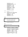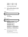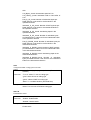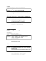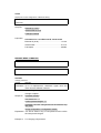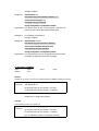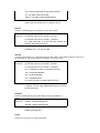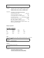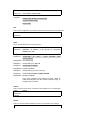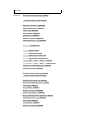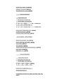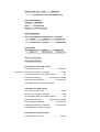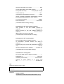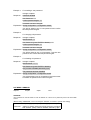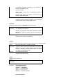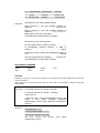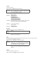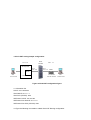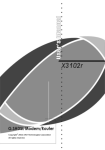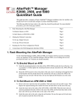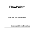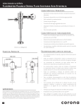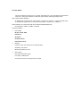
1
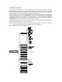
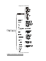
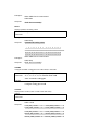
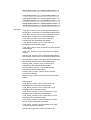
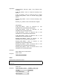
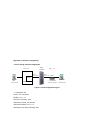
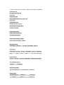
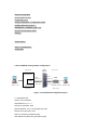
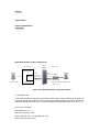
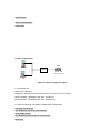
Console Setup
Connect the RS-232 console port to an ASCII data terminal or a PC with Widows serial Terminal
mode of VT-100 (Hyper Terminal). To Start the Hyper-terminal, following the steps below:
Start "Hyper-terminal" program -−
On Windows 98 or Windows NT: start Tool Bar Æ Program Æ Accessory Æ Hyper Terminal Group
Æ Double Click Hypertrm.exe Æ Enter Connection Name Æ Select Icon Æ Click OK
Select COM port to communicate with ATU-R100/R110/R200/R300/R110H
−
Choose direct to COM1 or COM2 Æ click OK
Set Port Properties -
Port Setting:
−
Bit per second: 9600
−
Data bits: 8
−
Stop bits: 1
−
Parity bits: None
−
Flow Control: None
Settings:
−
Function, arrow, and ctrl keys act as: Windows keys
−
Emulation: Auto-detect
−
Back-scroll buffer lines: 500
ASCII Setup:
−
Echo typed characters locally
−
Line delay: 0 milliseconds
−
Character line feeds t incoming line ends: enable
Command Line Interface
The command line interface allows you to change ADSL, ATM and Ethernet parameters, interchange
between bridge and route mode by using the “mode” command, and display the status as well. Some
commands must be followed by parameters for proper configuration to the modem, conventionally there
shall be a “space” between a command and its corresponding parameters.
The punctuation marks in syntax and parameters section have their different meanings. In the syntax, < >
mean the parameters enclosed in are compulsory, [ ] mean the parameter enclosed in are optional,
and | between parameters mean either….or. In the parameters, “ “ mean the parameters enclosed in
are Key Word. Furthermore, after power on the unit with console terminal, screen will show the prompt
as ATUR110R> for entering command without any password at first time.
There are two hierarchical levels in the command line interface. The command tree below will show user
the hierarchical relationship and commands supported:
Note 1: When the user enable password, the connection will time out after 10 minutes if no access to
modem. Entering password again is necessary to resume connection.
Note 2: All settings will effect only after saved.
a d sl
d e fa ult
la n
list
Main menu
m a na g e
―se tp a ss
m od e
p ing
q uic k
r1483
re sta rt
sa ve
sho w
ve r
d e lp vc
p filte r
se tp vc
se tq o s
bridge mode command tree
m od e
router mode command tree
COMMAND LINE INTERFACE CONVENTIONS
Help
help <command> home
HELP or ?
Lists all commands at the current level menu and follow by simple description of each command
Syntax:
help
Parameters:
Example:
> help
Syntax:
?
Parameters:
Example:
>?
HELP <command> or ? <command>
Display the usage of particular command in each level.
Syntax:
help <command>
Parameters:
command: Enter each command
Example:
adsl> help trellis
Display the syntax of trellis command
Response:
trellis
Syntax:
? <command>
Parameters:
command: Enter each command
Example:
adsl> help trellis
Response:
Display the syntax of trellis command
trellis
- <Enable>|<Disable> - Trellis encoding
- <Enable>|<Disable> - Trellis encoding
HOME
Go back to the upper level menu
Syntax:
Home
Parameters:
Example:
> home
Bridge mode CLI
MAIN MENU COMMANDS:
adsl
default
lan
list
manage
mode
ping
quick
r1483
restart
save
show
ver
ADSL
Enter to ADSL configuration menu. More commands under ADSL menu, see detail after.
Syntax:
adsl
Parameters:
Example:
> adsl
DEFAULT
Set all configuration to factory setting
Syntax:
Default
Parameters:
Example:
> default
Response:
The data set to default successfully.
Set ADSL configuration back to factory setting.
LAN
Enter to LAN menu. More commands under LAN menu, see detail after.
Syntax:
Lan
Parameters:
Example:
> lan
LIST
Display the status for each enabled VC
Syntax:
List
Parameters:
Example:
> list
Response:
Port ethernet
0: Enabled
TxPkts: 1
RxPkts: 0/0
Port adsl
0: Enabled TxPkts: 56
TxVPI/VCI: 8/35
Explanation:
RxPkts: 37/0
RxVPI/VCI: 8/35
Information for Ethernet port:
0 (Status of port number 1)..………………….….Enabled
TxPkts (transmitted packets)……………………………..1
RxPkts (received packets)….…………0/0 (correct/error)
Information for ADSL port:
0 (Status of port number 1)……………………….enabled
TxPkts (transmitted packets)……………………………56
RxPkts (received packets)…………...37/0 (correct/error)
TxVPI/VCI (transmitted VC)………………..…………8/35
RxVPI/VCI (received VC)……………………………..8/35
MANAGE
Enter to MANAGE configuration menu. More commands under MANAGE menu, see detail after.
Syntax:
manage
Parameters:
Example:
> manage
MODE
Select the modem as Bridge or router mode
Syntax:
mode
Parameters:
The default is bridge mode.
Example:
> manage
Response:
Please select bridge or router:(b/r,r)b
Current mode is bridge
>
PING
Ping a specific IP address for testing purpose
Syntax:
ping <ipaddress>
Parameters:
ipaddress: IP address, in the format of 4 decimals
separated by dots
Example1:
> ping xxx.xxx.xxx.xxx
Response:
ip: ping - reply received from xxx.xxx.xxx.xxx
Explanation: Successful ping
Example2:
> ping 299.999
Response:
Invalid IP
Explanation: Invalid IP address
Example3:
> ping xxx.xxx.xxx.xxx
Response:
ip: ping - no reply received
Explanation: Wrong IP address
If no reply received, the system will ping same IP
address continually until the system receiving reply or
pressing “Esc” to break.
QUICK
Enter a VC with RFC1483/bridge mode by an interactive user interface
Syntax:
quick
Parameters:
Example:
> quick
Response:
1 PVC existed, 7 PVCs available.
VPI(0-1023): 2[Enter]
VCI(1-65535): 34[Enter]
PCR(0-800): 800[Enter]
Packet Filter ( Any/Ip/Pppoe ): a[Enter]
Add another PVC ? (y/n): n[Enter]
Enable Spanning tree? (y/n) : y[Enter]
Configuration
MODE: Bridge
FUNCTION: R1483
Spanning Tree: Enable
# VPI
VCI
PCR
Package filter
1: 1
22
800
ANY
Preserve the configuration (y/n): y[Enter]
Type "save" to effect setting.
R1483
Enter to R1483 menu. More commands under R1483 menu, see detail after.
Syntax:
Parameters:
R1483
Example:
> r1483
RESTART
Reboot the SDSL modem
Syntax:
restart
Parameters:
Example:
> restart
Response:
SDRAM size = 0x800000, type = 0x5
NPnNo boot information block
Booting...
System starts...
ADSL Line Establishing
>
SAVE
Save the configuration into flash memory, and restart modem
Syntax:
save
Parameters:
Example:
> save
Response:
Saving configuration...Configuration saved.
Updating flash filing system ...
SDRAM size = 0x800000, type = 0x5
NPnNo boot information block
Booting...
System starts...
ADSL Line Establishing
>
Save configuration then restart modem
SHOW
Display the configuration of each enabled VC and Ethernet
Syntax:
show [lan]|[wan]
Parameters:
“lan”: display LAN configuration
“wan” display WAN configuration
Example 1:
> show lan
Response:
Ethernet ip: 0.0.0.0
Subnet mask: 0.0.0.0
FullDuplex:Disabled
Explanation:
Information for Local Ethernet IP, subnet mask and each
enabled VC
Ethernet IP (local)…………………………………...0.0.0.0
Subnet mask…………………………………………0.0.0.0
Full Duplex…………………………………………Disabled
Function (Protocol in use)………………………RFC1483
Example 2:
Response:
Explanation:
> show wan
FUNCTION VPI/VCI CLASS PCR(KBits) Spanning Pkt Filter
Rfc1483
8/35 ubr
640
Disable
ANY
VPI/VCI (Connected VC channel)…………………...8/35
CLASS (define QoS on the ATM network)……………ubr
PCR (Peak Cell Rate)….………… 640 (cells per second
Spanning (Spanning tree setting)…………………disable
Pkt Filter (packet control)..………………………Any
(Allow to pass both IP and PPPOE packet.)
(Note: IP – only allow to pass IP packet; PPPoE – only
allow to pass PPPoE packet)
VER
Display the software version number
Syntax:
Ver
Parameters:
Example:
> ver
Response:
Version : 2.21MJ
(2.21MJ-H50.1302-F2210.0406A 28/Oct/2000 12:21)
ADSL MENU COMMANDS:
Abort
bitdn
bitup
coding
Counts
default
ec_fdm
fails
Print
rx_bin
show
startup
Status
stnl
trellis
tw_pwr
tx_bin
ABORT
Terminate the ADSL physical link
Syntax:
abort
Parameters:
Example:
adsl> abort
BITDN
Display downstream bit loading values
Syntax:
bitdn
Parameters:
Example 1:
When ADSL line is connected:
adsl> bitdn
Response:
Downstream Bit loading value:
0 1 2 3 4 5 6 7 - 8 9 A B C D E F
0
1
2
3
4
5
6
7
8
9
a
b
c
d
e
f
0
0
0
0
0
0
0
0
-
0
0
0
0
0
0
0
0
0
0
0
0
0
0
0
0
-
0
0
0
0
0
0
0
0
0
0
0
0
0
0
0
0
-
0
0
0
2
2
2
3
4
4
5
6
6
6
6
7
7
-
7
7
7
8
8
8
7
8
0
8
8
8
8
8
8
7
-
8
7
7
8
8
7
9
9
8
7
7
8
8
9
9
8
-
8
9
9
7
8
7
9
8
10 7
8
9
8
7
7
8
-
7
7
8
9
9
9
7
7
8
8
9
9
8
8
8
-
8
8
9 10
8
10 10 10
9
8
7
8
8 10
8
10 10 10 10 10 10 10
7
9
-
8
9
8
7
8
9
7
8
8
-
9
9
8
7
7
8
8
8
10 7
9
9
8
7
8
7
-
9
9
7
8
9
9
7
9
7
9
8
9
9
7
7
-
8
8
8
9
10 10 10 10
10 10 10 10
9
9
8
8
-
8
7
9
8
8
8
9
9
7
8
7
8
9
8
7
7
-
8
8
8
7
8
9
8
7
9
6
8
8
8
7
8
8
-
7
7
7
8
9
8
7
7
7
8
8
7
8
8
8
7
-
7
7
7
7
6
6
6
5
8
Example 2:
When ADSL line is unconnected.
adsl> bitdn
Response:
ADSL line is not ready!!
BITUP
Display upstream bit loading values
Syntax:
bitup
Parameters:
Example 1:
When ADSL line is connected:
adsl> bitup
Response:
Upstream Bit loading value:
| 0
1 2 3
4 5
6 7 -
8 9 A B C D E F
==+=================================================
Example 2:
0|
2
0
0
0
0
0
0
0
-
0
0
0
0
0
0
0
0
1|
0
0
0
0
0
0
0
0
-
0
0
0
0
0
0
0
0
When ADSL line is unconnected:
adsl> bitup
Response:
ADSL line is not ready!!
CODING
Configure the ADSL coding gain from 0 dB to 6dB, or automatic.
Syntax:
coding <0>|<1>|<2>|<3>|<4>|<5>|<6>|<auto>
Parameters:
“0”,”1”,”2”,”3”,”4”,”5”,”6”: decimal value of dB
“auto”: automatic coding gain
Example:
adsl> coding 3
Configure coding gain to 3dB
COUNTS
Display ADSL counters (clean counter value after reset)
Syntax:
counts
Parameters:
Example 1:
When ADSL line is connected:
adsl> counts
Response:
Local_RSI_Counter
9
Local_RSF_Counter
0
Local_CRSI_Counter
2
Local_CRSF_Counter
0
Local_SEF_Couner
0
Local_LOS_Counter
0
Remote_RSI_Counter
0
Remote_RSF_Counter
0
Remote_CRSF_Counter
0
Remote_CRSI_Counter 0
Explanation:
Remote_SEF_Counter
0
Remote_LOS_Counter
0
Local_NCDI_Counter
0
Local_NCDF_Counter
0
Local_OCDI_Counter
0
Local_OCDF_Counter
0
Local_HECI_Counter
0
Local_HECF_Counter
0
Remote_NCDI_Counter 0
Remote_NCDF_Counter
0
Remote_HECI_Counter 0
Remote_HECF_Counter
0
Local_RSI_Counter: count of near-end Reed-Solomon
forward error corrections for the interleaved data stream
Local_RSF_Counter: count of near-end Reed-Solomon
forward error corrections for the fast data stream
Local_CRSI_Counter: count of CRC near-end
anomalies for the interleaved data stream
Local_CRSF_Counter: count of CRC near-end
anomalies for the fast data stream
Local_SEF_Couner: count of near-end severely errored
frame defects
Local_LOS_Counter: count of near-end loss of signal
defects
Remote_RSI_Counter: count of far-end Reed-Solomon
forward error corrections for the interleaved data stream
Remote_RSF_Counter: count of far-end Reed-Solomon
forward error corrections for the fast data stream
Remote_CRSI_Counter: count of CRC far-end
anomalies for the interleaved data stream
Remote_CRSF_Counter: count of CRC far-end
anomalies for the fast data stream
Remote_SEF_Counter: count of far-end severely
errored frame defects
Remote_LOS_Counter: count of far-end loss of signal
defect
ATM counters:
Local_NCDI_Counter: count of near-end no cell
delineation for the interleaved data stream.
Local_NCDF_Counter: count of near-end no cell
delineation for the fast data stream
Local_OCDI_Counter: count of near-end out of cell
delineation for the interleaved data stream
Local_OCDF_Counter: count of near-end out of cell
delineation for the fast data stream
Local_HECI_Counter: near-end header error check
counter for the interleaved data stream
Local_HECF_Counter: near-end header error check
counter for the fast data stream
Remote_NCDI_Counter: count of far-end no cell
delineation for the interleaved data stream.
Remote_NCDF_Counter: count of far-end no cell
delineation for the fast data stream
Remote_HECI_Counter: far-end header error check
counter for the interleaved data
Remote_HECF_Counter: far-end header error check
counter for the fast data stream
Example 2:
Response:
When ADSL line is unconnected:
adsl> counts
ADSL line is not ready!!
DEFAULT
Set ADSL parameter back to factory setting
Syntax:
default
Parameters:
Example:
adsl> default
Response:
Set ADSL configuration back to factory setting.
EC_FDM
Configure ADSL as Echo Cancellation mode or FDM mode
Syntax:
ec_fdm <Ec>|<Fdm>
Parameters:
Ec: Echo cancellation mode is selected
Fdm: FDM mode is selected
Example:
adsl> ec_fdm fdm
Select FDM mode
FAILS
Display ADSL error counts
Syntax:
fails
Parameters:
Example 1:
When ADSL line is connected:
adsl> fails
Response:
Overall_Failure
0
Local_Sef_Failure
0
Local_Los_Failure
0
Remote_Pow_Failure
0
Remote_Sef_Failure
0
Remote_Los_Failure
0
Local_ncdI_Failure
0
Local_ncdF_Failure
0
Local_lcdI_Failure
0
Local_lcdF_failure
0
Remote_ncdI_Failure 0
Remote_lcdI_Failure
0
Remote_ncdF_Failure 0
Remote_lcdF_Failure
0
Explanation:
Overall_Failure: Non-zero value if any failures have
occurred
Local_Sef_Failure: count of near-end severely error
frames
Local_Los_Failure: count of near-end loss of signal
Remote_Pow_Failure: count of far-end dying gasp
frames
Remote_Sef_Failure: count of far-end severely error
framed
Remote_Los_Failure: count of far-end loss of signal
ATM failures:
Local_ncdI_Failure: count of near-end
delineation for the interleaved data stream
no
cell
Local_ncdF_Failure: count of near-end
delineation for the fast data stream
no
cell
Local_lcdI_Failure: count of near-end loss of cell
delineation for the interleaved data stream
Local_lcdF_failure: count of near-end loss of cell
delineation for the fast data stream
Remote_ncdI_Failure: count of far-end
delineation for the interleaved data stream
no
cell
Remote_ncdF_Failure: count of
delineation for the fast data stream
no
cell
far-end
Remote_lcdI_Failure: count of far-end loss of cell
delineation for the interleaved data stream
Remote_lcdF_Failure: count of far-end loss of cell
delineation for the fast data stream
Example 2:
Response:
When ADSL line is unconnected:
adsl> counts
ADSL line is not ready!!
PRINT
Display ADSL miscellaneous status
Syntax:
print
Parameters:
Example 1:
When ADSL line is connected:
adsl> print
Response:
ADSL Firmware version
ANNEX_A CPE 2210
OP state
ShowTime
Last Failed Status
(0)
Start Progress
ad
Watchdog Timer
53
Down Stream Noise Margin
24 dB
Local Attenuation
0 dB
Remote Attenuation
31 dB
Coding Gain
6 dB
RS Frame TxCount
3249108
RS Frame RxCount
812277
00Cell TxCount
0
Cell RxCount
Example 2:
162
When ADSL line is unconnected:
adsl> print
Response:
ADSL Firmware version
ANNEX_A CPE 2210
OP state
handshake
Last Failed Status
(0)
Start Progress
a0
Watchdog Timer
53
RX_BIN
Allow the user to limit bin number used for special configurations in receive signal
Syntax:
rx_bin <start_bin> <end_bin>
Parameters:
start bin: Start bin, the lowest bin number
end bin: End bin, the highest bin number
(1 to 255: decimal value of bin number)
Example:
adsl> rx_bin 3 4
Set start bin = 3 and end bin = 4
SHOW
Display the ADSL parameter configuration
Syntax:
Show
Parameters:
Example:
adsl> show
Response:
ADSL setting :
Current
Ineffective
------------------------------------------------------------------------Local line code
MULTIMODE
MULTIMODE
Trellis encoding
Enable
Enable
EC/FDM mode
FDM
EC
Coding gain
AUTO
AUTO
Transmit Power Attenuation 0 dB
0 dB
Tx Start bin
6 (H)
6 (H)
Tx End bin
1f (H)
1f (H)
Rx Start bin
20 (H)
6 (H)
Rx End bin
ff (H)
ff (H)
Type "home" and then "save" to effect setting
Explanation:
Ineffective: configuration setting that will become
“current” only after save and restart this unit or using
startup command that will malfunction after turning off
this unit
Current: current status of ADSL line
STARTUP
Restart the ADSL link
Syntax:
startup
Parameters:
Example:
adsl> startup
Response:
start to re-Sync. ...
ADSL Line Establishing
STATUS
Display the ADSL line status
Syntax:
status
Parameters:
Example:
adsl> status
Response:
Standard mode
T1_413
Framing_Overhead_actual
0
AS0_Dn_Bytes_Actual
0kbps
AS0_Dn_Latency_Actual
< Interleave >
LS0_Up_Bytes_Actual
0kbps
LS0_Up_Latency_Actual
< Interleave >
Fast_R_Up_Actual
0
Interleave_S_Up_Actual
0
Interleave_D_Up_Actual
0
Interleave_R_Up_Actual
0
Fast_R_Dn_Actual
0
Interleave_S_Dn_Actual
0
Interleave_D_Dn_Actual
0
Interleave_R_Dn_Actual
0
Explanation:
Trellis < Disable >
Standard mode: ADSL coding Type at local side
Framing_Overhead_actual: Frame overhead type
Trellis: enable/disable trellis
AS0_Dn_Bytes_Actual: downstream speed of AS0
AS0_Latency_Actual: Interleave buffer or fast buffer of
AS0
LS0_Bytes_Actual: downstream speed of LS0
LS0_Latency_Actual: Interleave buffer or fast buffer of
LS0
Fast_R_UP_Actual: Number of redundant bytes per
Reed-Solomon code word for the fast buffer in the
upstream direction
Interleave_S_UP_Actual: Number of DMT symbols per
Reed-Solomon code word for the interleaved buffer in
the upstream direction
Interleave_D_UP_Actual: interleaving depth in the
upstream direction
Interleave_R_UP_Actual: Number of redundant bytes
per Reed-Solomon code word for the interleaved buffer
in the upstream direction
Fast_R_DOWN_Actual: Number of redundant bytes per
Reed-Solomon code word for the fast buffer in the
downstream direction
Interleave_S_DOWN_Actual: Number of DMT symbols
per Reed-Solomon code word for the interleaved buffer
in the downstream direction
Interleave_D_DOWN_Actual: interleaving depth in the
downstream direction
Interleave_R_DOWN_Actual: Number of redundant
bytes per Reed-Solomon code word for the interleaved
buffer in the downstream direction
STNL
Configure the ADSL coding type at local side
Syntax:
stnl <T1.413>|<g.lite>|<g.dmt<|<Multi> (T1.413 MultiVendors)
Parameters:
“T1.413”: select T1.413 as coding type
“g.lite”: select G.Lite as coding type
“g.dmt”: select G.DMT as coding type
“Multi”: T1.413 Multi-Vendors (auto detection)
Example:
adsl> stnl T
Select T1.413 as the ATU-R200 coding type
TRELLIS
Enable/disable Trellis
Syntax:
trellis <Enable>|<Disable>
Parameters:
“Enable”: Enable trellis
“Disable”: Disable trellis
Example:
adsl> trellis enable
Enable trellis
TX_PWR
Configure transmitted power attenuation from 0dB to 12dB
Syntax:
tx_pwr <0>……<12>
Parameters:
0……12: 0 to 12, decimal value of dB
Example:
adsl> tx_pwr 11
Configure transmitted power attenuation as 11 dB
TX_BIN
Allow the user to limit bins used for special configurations in transmit signal
Syntax:
tx_bin <start_bin> <end_bin>
Parameters:
start bin: Start bin, the lowest bin number
end bin: End bin, the highest bin number
(1 to 255: decimal value of bin number)
Example:
adsl> tx_bin 3 4
Set start bin to 3 and end bin to 4
LAN MENU COMMANDS
fullduplex
setip
show
FULLDUPLEX
Enable or disable full duplex operation
Syntax:
fullduplex <disable>|<enable>
Parameters:
“disable”: disable full duplex (half duplex operation)
“enable”: enable full duplex operation
(The default is disable)
Example:
lan> fullduplex enable
Enable full duplex operation
SETIP
Setup the IP address, and subnet mask for the Ethernet LAN connection
Syntax:
setip <etherip>[<subnet mask>]
Parameters:
etherip: Ethernet IP address, in the format of 4 decimals
separated by dot
subnet mask: Subnet mask, the default is 255.255.255.0
Example:
lan> setip 192.168.2.32
Set a new IP address = 192.168.2.32 and
Subnet mask is default = 255.255.255.0
SHOW
Display the current configuration of Ethernet setting.
Syntax:
Show
Parameters:
Example:
lan> show
Response:
Ethernet ip: 0.0.0.0
Subnet mask: 0.0.0.0
FullDuplex:Disable
Explanation:
Information for Local Ethernet IP, subnet mask
Ethernet IP (local)…………………………………...0.0.0.0
Subnet mask………………………………………...0.0.0.0
Full Duplex…………………………………………..disable
MANAGE MENU COMMANDS
SETPASS
Change password
Syntax:
setpass
Parameters: Up to 20 alphanumeric characters. Upper case and
lower case are different numbers.
Example 1: For enabling a new password
manage> setpass
Response:
Password disabled
New Password: ****
Confirm password again: ****
Password has been changed and will be effective only
after save!
Saving configuration...Configuration saved.
Explanation: You will be asked to key in new password and confirm
the new password again.
Example 2: For changing old password:
manage> setpass
Response:
Old Password: ****
New Password (press ENTER to disable): ****
Confirm password again: ****
Password has been changed
Saving configuration...Configuration saved.
Explanation: You will be asked to key in old password. Type the new
password and confirm the new password again.
Example 3: For disabling old password:
manage> setpass
Response:
Old Password: ********
New Password (press ENTER to disable):
Are you sure to disable password (y/n)?
The password has been disabled
Saving configuration...Configuration saved.
Explanation: You will be asked to key in old password and press enter
to disable old password and confirm it again.
R1483 MENU COMMAND
delpvc
pfilter
setspan
show
setpvc
setqos
DELPVC
Disable VC by giving a VPI and VCI numbers defined by setpvc command previously
Syntax:
delpvc <all>|[<vpi>/]<vci>
Parameters:
“all”: delete all VC
vpi: decimal value of VPI number, 0 to 1023
vci: decimal value of VCI number, 1 to 65535
Example:
r1483> delpvc
Disable VC in configuration setting
PFILTER
Packet filtering control on a specific VC
Syntax:
pfilter [<vpi>/]<vci> <any|ip|pppoe>
Parameters:
vpi: decimal value of VPI number, 0 to 1023.
vci: decimal value of VCI number, 1 to 65535.
(vpi, vci defined by setpvc command previously)
“any”: Allow to pass both IP and PPPOE packet
“ip”: only allow to pass IP packet
“pppoe”: only allow to pass PPPoE packet
Example:
r1483> pfilter 1/32 ip
Allow to pass IP packet only in a specific 1/32 VC
SETPVC
Enable an r1483 bridging VC by giving the VCI and VPI numbers
Syntax:
setpvc [<vpi>/]<vci> [pcr <pcr>]
Parameters:
vpi: decimal value of VPI number, 0 to 1023
vci: decimal value of VCI number, 1 to 65535
pcr: Peak Cell Rate, 0 to 800 cells per second, the
default is 800 cells per second
Example:
r1483> setpvc 1/32 pcr 600
Configure vpi=1, vci= 32, pcr=600
SETQOS
Configure each enabled VC in r1483 that should use UBR, CBR or VBR (define the Quality of Service on
the ATM network), also set the speed of the ATM link in cells per second
Syntax:
setqos [<vpi>/]<vci> <ubr|cbr|vbr(nrt)> <pcr>
Parameters:
vpi: decimal value of VPI number, 0 to 4095.
vci: decimal value of VCI number, 1 to 65535.
(vpi, vci defined by setpvc command previously)
“ubr”: Unspecified Bit Rate
“cbr”: Constant Bit Rate
“vbr”: Variable Bit Rate
pcr: Peak Cell Rate, 0 to 800 cells per second
Example:
r1483> setqos 1/32 ubr 640
Configure 1/32 VC using UBR and 640 cells per second
for the connection.
SETSPAN
Enable or disable Spanning Tree under Bridge mode for all enabled VC
Syntax:
setspan <Enable>|<Disable>
Parameters:
“Enable”: enable spanning tree
“Disable”: disable spanning tree
Example:
r1483> setspan Disable
Disable spanning tree
SHOW
Display the configuration of r1483 bridge setting.
Syntax:
Show
Parameters:
Example:
r1483> show
Response:
FUNCTION
VPI/VCI
CLASS
Rfc1483
8/35
ubr
Explanation:
PCR(KBits)
640
Spanning
Pkt Filter
Disable
ANY
Information for RFC1483 bridge setting:
Function (Protocol in use)………………………RFC1483
VPI/VCI (Connected VC channel)…………………...8/35
CLASS (define QoS on the ATM network)……………ubr
PCR (Peak Cell Rate)….…………640 (cells per second)
Spanning (Spanning tree setting)…………………disable
Pkt Filter (packet control)..………………………Any
(Allow to pass both IP and PPPOE packet.)
(Note: IP – only allow to pass IP packet; PPPoE – only
allow to pass PPPoE packet)
Router mode CLI
MAIN MENU COMMANDS
adsl
default
ipoa
lan
list
manage
mode
pat
ping
pppoa
quick
r1483
restart
Rtable
save
show
ver
ADSL
Enter to ADSL configuration menu. More commands under ADSL menu, see detail after.
Syntax:
Adsl
Parameters:
Example:
ATUR110R> adsl
DEFAULT
Set all configuration to factory setting
Syntax:
Default
Parameters:
Example:
ATUR110R> default
Response:
The data set to default successfully.
Set ADSL configuration back to factory setting.
IPOA
Enter to IPOA menu. More commands under IPOA menu, see detail after.
Syntax:
Ipoa
Parameters:
Example:
ATUR110R> ipoa
LAN
Enter to LAN menu. More commands under LAN menu, see detail after.
Syntax:
Lan
Parameters:
Example:
ATUR110R> lan
LIST
Display the status for each enabled VC
Syntax:
List
Parameters:
Example:
ATUR110R> list
Response:
Port ethernet
0: edd
TxPkts: 1
RxPkts: 0/0
Port adsl
0: ip TxPkts: 56
RxPkts: 37/0
8/35 RxVPI/VCI: 8/35
Explanation:
TxVPI/VCI:
Information for Ethernet port:
0 (package type of channel number 1)..……………..edd
TxPkts (transmitted packets)……………………………..1
RxPkts (received packets)….…………0/0 (correct/error)
Explanation:
Information for ADSL port:
0 (package type of channel number 1)………………….ip
TxPkts (transmitted packets)……………………………56
RxPkts (received packets)…………...37/0 (correct/error)
TxVPI/VCI (transmitted VC)………………..…………8/35
RxVPI/VCI (received VC)……………………………..8/35
MANAGE
Enter to MANAGE configuration menu. More commands under MANAGE menu, see detail after.
Syntax:
manage
Parameters:
Example:
ATUR110R> manage
MODE
Select the modem as Bridge or router mode
Syntax:
mode
Parameters:
The default is bridge mode.
Example:
>> manage
Response:
Please select bridge or router:(b/r,b)r
Current mode is router
ATUR110R>
PAT
Enter to PAT configuration menu. More commands under PAT menu, see detail after.
Syntax:
pat
Parameters:
Example:
ATUR110R> pat
PING
Ping a specific IP address for testing purpose
Syntax:
ping <ipaddress>
Parameters:
ipaddress: IP address, in the format of 4 decimals
separated by dots
Example1:
ATUR110R> ping xxx.xxx.xxx.xxx
Response:
ATUR110R> ip:
xxx.xxx.xxx.xxx
ping
-
reply
received
from
Explanation: Successful ping
Example2:
ATUR110R> ping 299.999
Response:
ATUR110R> Invalid IP
Explanation: Invalid IP address
Example3:
ATUR110R> ping xxx.xxx.xxx.xxx
Response:
ATUR110R> ip: ping - no reply received
Explanation: Wrong IP address
If no reply received, the system will ping same IP
address continually until the system receiving reply or
pressing “Esc” to break.
PPPOA
Enter to PPPOA menu. More commands under PPPOA menu, see detail after.
Syntax:
pppoa
Parameters:
Example:
ATUR110R> pppoa
QUICK
Enter VC with RFC1483/IPoA/PPPoA mode by an interactive user interface
Syntax:
Quick
Parameters:
Example:
ATUR110R> quick
Response:
R1483(r)/ IPoA(i)/ PPPoA(p): r[Enter]
0 PVC existed, 8 PVCs available.
Ethernet IP: 210.62.2.185[Enter]
Subnet mask (0.0.0.0): [Enter]
VPI(0-1023): 5[Enter]
VCI(1-65535): 35[Enter]
PCR(0-800): 640[Enter]
WAN IP : 210.62.6.185[Enter]
Add another PVC ? (y/n): n[Enter]
Configuration
MODE: Router
FUNCTION: R1483
Ethernet IP: 210.62.2.185
Subnet Mask: 255.255.255.0
#
VPI
1: 5
VCI
PCR
WAN IP
35
640
210.62.6.185
Preserve the configuration (y/n): n[Enter]
Continue quick (y/n): y[Enter]
R1483(r)/ IPoA(i)/ PPPoA(p): i[Enter]
0 PVC existed, 8 PVCs available.
Ethernet IP (210.62.2.134) : [Enter]
Subnet mask (255.255.255.0) : [Enter]
VPI(0-4095): 8[Enter]
VCI(1-65535): 32[Enter]
WAN IP : 210.62.5.183[Enter]
Dynamic (d) / Static (s): d[Enter]
RIP1(r1)/ RIP2(r2)/ RIP 1&2(r1&2): r1[Enter]
Add another PVC ? (y/n): y[Enter]
VPI(0-4095): 2[Enter]
VCI(1-65535): 32[Enter]
WAN IP : 210.62.5.187[Enter]
Dynamic (d) / Static (s): s[Enter]
Gateway : 210.62.5.175[Enter]
Add another PVC ? (y/n): n[Enter]
Setup Configuration
FUNCTION: IPOA
Ethernet IP: 210.62.2.134
Subnet Mask: 255.255.255.0
# VPI VCI WAN IP
RIP
1: 8
32
210.62.5.183
1
2: 2
32
210.62.5.187
Gateway IP
210.62.5.175
Preserve the configuration (y/n) : n[Enter]
Continue quick (y/n) : y[Enter]
R1483(r)/ IPoA(i)/ PPPoA(p): p[Enter]
0 PVC existed, 1 PVC available.
Ethernet IP (210.62.2.134) : [Enter]
Subnet mask (255.255.255.0) : [Enter]
VPI(0-4095): 6[Enter]
VCI(1-65535): 33[Enter]
Authentication( PAP(p)/CHAP(c)/None(n) ): p[Enter]
User name: xavi[Enter]
Password: ********[Enter]
Setup Configuration
FUNCTION: PPPOA
Ethernet IP: 210.62.2.134
Subnet Mask: 255.255.255.0
# VPI
VCI
AUTH
USERID
1: 6
33
PAP
xavi
Preserve the configuration (y/n) : n
Continue quick (y/n) : n
Configuration will have no effect until after save and
restart.
R1483
Enter to R1483 menu. More commands under R1483 menu, see detail after.
Syntax:
r1483
Parameters:
Example:
ATUR110R> r1483
RESTART
Reboot the ADSL modem
Syntax:
restart
Parameters:
Example:
ATUR110R> restart
Response:
SDRAM size = 0x800000, type = 0x5
NPnNo boot information block
Booting...
System starts...
ADSL Line Establishing
RTABLE
Enter to RTABLE menu. More commands under RTABLE menu, see detail after.
Syntax:
rtable
Parameters:
Example:
ATUR110R> rtable
SAVE
Save the configuration into flash memory, and restart modem
Syntax:
save
Parameters:
Example:
ATUR110R> save
Response:
Saving configuration...Configuration saved.
Updating flash filing system ...
SDRAM size = 0x800000, type = 0x5
NPnNo boot information block
Booting...
System starts...
ADSL Line Establishing
ATUR110R>
Save configuration then restart modem
SHOW
Display the configuration of each enabled VC and Ethernet
Syntax:
show [lan]|[wan]
Parameters:
Example:
ATUR110R> show lan
Response:
Ethernet ip: 192.168.2.1
Subnet mask: 255.255.255.0
FullDuplex: Disable
DHCP Server setup:
range1: 0.0.0.0 to 0.0.0.0
max lease time: 86400
DHCP current setting: disable.
DHCP ineffective setting: disable.
Explanation:
Information for Local Ethernet IP, subnet mask
Ethernet IP (local)…………………………..…192.168.2.1
Subnet mask………………………………..255.255.255.0
Full Duplex……………………………………….…Disable
Information for DHCP server setting:
Range1 (First IP to last IP address).….0.0.0.0 to 0.0.0.0
Max lease time (infinite)..……..………….86400 seconds
ATUR110R> show wan
Example 2:
RFC1483 setting:
Response:
FUNCTION
VPI/VCI CLASS PCR(KBits) Wan IP
Rfc1483
8/35
ubr
640
210.62.2.183
FUNCTION VPI/VCI CLASS PCR
Wan IP
GatewayIP
IPoA
8/32
ubr
640
210.62.2.195
210.62.2.185
IPoA
5/33
ubr
640
210.62.2.198
210.62.2.185
IPoA setting:
PPPoA setting:
Function VPI/VCI CLASS PCR(KBits)
UserID/Authentication
PPPoA 2/32 ubr
640
LLC=Disable
xavi/CHAP
Echo interval time: 60 s
PAT enabled interface:
Interface
IP address
IPoA
210.62.2.195
PPPoA
???.???.???.???
PAT incoming table:
No. i/f name|WanIP Port/Protocol
1
2
pppoa
210.62.2.195
Server IP
434/udp
192.62.2.134
232/tcp
192.62.2.166
Routing Table:
No. Destination IP
SubMask
1 192.62.2.0
255.255.255.0
Gateway IP
210.62.2.135
Effective routing table:
Routing table is empty
Information for RFC1483 setting:
Function (Protocol in use)………………………RFC1483
Explanation:
VPI/VCI (Connected VC channel)…………………...8/35
CLASS (define QoS on the ATM network)……………ubr
PCR (Peak Cell Rate)….…………640 (cells per second)
Wan IP (R1483 routing IP)………………….210.62.2.183
(The default RFC1483 setting is Empty)
Information for IPoA setting:
Function (Protocol in use)……………………………IPoA
VPI/VCI (Connected VC channel)……………………8/32
CLASS (define QoS on the ATM network)……………ubr
PCR (Peak Cell Rate)….…………640 (cells per second)
Wan IP (WAN IP address)……….…………210.62.2.195
GatewayIP (Gateway IP address)…………210.62.2.185
(The default IPoA setting is Empty)
Information for PPPoA setting:
Function (Protocol in use)…………………………PPPoA
VPI/VCI (Connected VC channel)……………………2/32
CLASS (define QoS on the ATM network)……………ubr
PCR (Peak Cell Rate)….…………640 (cells per second)
UserID (User ID)………………………………………xavi
Authentication (Authentication protocol)…………..CHAP
(CHAP: challenge handshake authentication protocol,
PAP: password authentication, none: neither )
LLC (Logic link control)…………………………….disable
Echo interval time……..………………………60 seconds
(The default PPPoA setting is Empty)
Information for PAT each enabled interface:
IPoA (protocol in use and enabled interface IP
address)…….………………………………..210.62.2.195
PPPoA (protocol in use and enabled interface IP
address)…….……………………………???.???.???.???
(Before get IP from service provider)
(The default PAT enabled interface is Empty)
Information for PAT incoming table:
No. (PAT table number, assign by system)……………..1
I/f name|Wanip (enabled interface and WAN IP
address)………………………………………………pppoa
Port/Protocal (Port number and transmitted Protocol in
use)………………………………………………….434/udp
Server IP (global server IP address)………192.62.2.134
(The default PAT incoming table is Empty)
Information for routing table:
No. (routing table number, assign by system)………….1
Destination IP…………………………………...192.62.2.0
SubMask (subnet mask)………………..…255.255.255.0
Gateway IP (IPoA gateway IP or R1483 Wan
IP).…………………………………………….210.62.2.135
VER
Display the software version number
Syntax:
Ver
Parameters:
Example:
ATUR110R> ver
Response:
Version : 2.21MJ
(2.21MJ-H50.1302-F2210.0406A 28/Oct/2000 12:21)
ADSL MENU COMMANDS:
Please refer to Bridge mode CLI
IPOA MENU COMMANDS
Delwanip
setqos
setwanip
show
DELWANIP
Disable VC by giving a VPI and VCI numbers defined by setwanip command previously. (User can set
up to 8 PVC in IPoA configuration)
Syntax:
delwanip <all>|[<vpi>/]<vci>
Parameters:
“all”: delete all routing information
vpi: decimal value of VPI number, 0 to 1023
vci: decimal value of VCI number, 1 to 65535
Example:
ipoa> delwanip 1/32
Disable VC=1/32 in configuration setting.
SETQOS
Configure each enabled VC in IPoA that should use UBR, CBR or VBR (define the Quality of Service on
the ATM network), also set the speed of the ATM link in cells per second
Syntax:
setqos [<vpi>/]<vci> <ubr|cbr|vbr(nrt)> <pcr>
Parameters:
vpi: decimal value of VPI number, 0 to 4095
vci: decimal value of VCI number, 1 to 65535
(vpi, vci defined by setwanip command previously)
“ubr”: Unspecified Bit Rate
“cbr”: Constant Bit Rate
“vbr”: Variable Bit Rate
pcr: Peak Cell Rate, 0 to 800 cells per second
Example:
ipoa> setqos 1/32 ubr 640
Configure 1/32 VC using UBR and 640 cells per second
for the connection.
SETWANIP
Enable a VC by giving a VPI and VCI numbers, also assign a WAN IP and gateway IP address
Note: wanip and gatewayip must be in the same subnet mask
Syntax:
setwanip [<vpi>/]<vci> <wanip> <gatewayip>
Parameters:
vpi: decimal value of VPI number, 0 to 4095
vci: decimal value of VCI number, 1 to 65535
wanip: WAN IP address, in the format of 4 decimals
separated by dot
gatewayip: gateway IP address, in the format of 4
decimals separated by dot
Example:
ipoa> setwanip 1/32 192.168.2.34 192.168.2.58
Configure VPI=1, VCI=32, WAN IP=192.168.2.34, and
gateway IP=192.168.2.58
SHOW
Display the configuration of IPoA routing setting.
Syntax:
Show
Parameters:
Example:
ipoa> show
Response:
IPoA setting:
Explanation:
FUNCTION VPI/VCI CLASS PCR(KBits) WanIP
GatewayIP
IPoA
210.62.2.185
8/32 ubr
640
210.62.2.195
Information for IPoA setting:
Function (Protocol in use)……………………………IPoA
VPI/VCI (Connected VC channel)……………………8/32
CLASS (define QoS on the ATM network)……………ubr
PCR (Peak Cell Rate)….…………640 (cells per second)
Wan IP (WAN IP address)……….…………210.62.2.195
GatewayIP (Gateway IP address)…………210.62.2.185
(The default IPoA setting is Empty)
LAN MENU COMMANDS
dhcpserver
fullduplex
setdhcp
setip
show
DHCPSERVER
Configure a range of IP addresses that are associated with subnet mask used for DHCP server
Notice: the IP addresses should be in the same subnet mask
Syntax:
dhcpserver <range1 startIP> <range1 endIP> [<range2
startIP> <range2 endIP>] [<max-lease-time>]
Parameters:
range1 startIP: the first IP address in range 1 for a
particular subnetwork, in the format of 4 decimals
separated by dot
range1 endIP: the last IP address in range 1 for a
particular subnetwork, in the format of 4 decimals
separated by dot
range2 startIP: the first IP address in range 2 for a
particular subnetwork, in the format of 4 decimals
separated by dot
range2 endIP: the last IP address in range 2 for a
particular subnetwork, in the format of 4 decimals
separated by dot
max-lease-time: maximum lease time, the default is
86400 seconds
Example:
lan> dhcpserver 192.168.2.32 192.168.2.126
Setup IP address of range 1 from 192.168.2.32 to
192.168.2.126
Setup Domain-Name-Servers IP addresses available to the client
Syntax:
dhcpserver dns <dns ip1> [<dns ip2>]
Parameters:
dns ip1: Domain-name-servers IP address 1
dns ip2: Domain-name-servers IP address 2
Example:
lan> dhcpserver dns 192.168.2.32
Setup domain-name-servers IP address= 192.168.2.32
FULLDUPLEX
Enable or disable full duplex operation
Syntax:
fullduplex <disable>|<enable>
Parameters:
“disable”: disable full duplex (half duplex operation)
“enable”: enable full duplex operation
Example:
> lan> fullduplex enable
Enable full duplex operation
SETDHCP
Select DHCP mode 0f the unit
(Note: user has to set dhcpserver command in advance)
Syntax:
setdhcp [server|disable]
Parameters:
“server”: Select unit as server mode
“disable”: disable DHCP
Example:
lan> setdhcp server
Select the unit as DHCP server mode
SETIP
Setup IP address, and subnet mask for the Ethernet LAN connection
Syntax:
setip <etherip> [subnet mask]
Parameters:
etherip: Ethernet IP address, in the format of 4 decimals
separated by dot
subnet mask: Subnet mask, the default is 255.255.255.0
Example:
lan> setip 192.168.2.32
Set a new IP address = 192.168.2.32 and
Subnet mask is default = 255.255.255.0
SHOW
Display the current configuration of Ethernet and the DHCP setting.
Syntax:
Show
Parameters:
Example:
lan> show
Response:
Ethernet ip: 192.168.2.1
Subnet mask: 255.255.255.0
FullDuplex: Disable
DHCP Server setup:
range1: 0.0.0.0 to 0.0.0.0
max lease time: 86400
DHCP current setting : disable.
DHCP ineffective setting : disable.
Explanation:
Information for Local Ethernet IP, subnet mask
Ethernet IP (local)……………………………..192.168.2.1
Subnet mask………………………………..255.255.255.0
Full Duplex…………………………………………..Disable
Information for DHCP server setting:
Range1 (First IP to last IP address).….0.0.0.0 to 0.0.0.0
Max lease time (infinite)..……..………….86400 seconds
MANAGE MENU COMMANDS
SETPASS
Change password
Syntax:
setpass
Parameters: Up to 20 alphanumeric characters. Upper case and
lower case are different numbers.
Example 1: For enabling a new password
manage> setpass
Response:
password disabled
New Password: ****
Confirm password again: ****
Password has been changed.
Explanation: Saving configuration...Configuration saved.
You will be asked to key in new password and confirm
the new password again.
Example 2:
For changing old password:
Response:
manage> setpass
Old Password: ****
New Password (press ENTER to disable): ****
Confirm password again: ****
Password has been changed
Explanation: Saving configuration...Configuration saved.
You will be asked to key in old password. Type the new
password and confirm the new password again.
Example 3:
For disabling old password:
Response:
manage> setpass
Old Password: ********
New Password (press ENTER to disable):
Are you sure to disable password (y/n)?y
The password has been disabled
Explanation: Saving configuration...Configuration saved.
You will be asked to key in old password and press enter
to disable old password and confirm it again.
PAT MENU COMMAND
addpatin
delpatin
setpat
show
ADDPATIN
This command is used to enable a local IP address as a server for a particular protocol to allow WAN
access
(Before setting “ADDPANIN”, user must configure “SETPAT” to activate a specific PAT setting)
Syntax:
addpatin <pppoa|wanip> <port>/<udp|tcp> <serverip>
Parameters:
“pppoa” or wanip: select one of link protocol to configure
PAT address. (wanip: WAN IP address, defined by ipoa
-> setwayip command previously, in the format of 4
decimals separated by dot)
port: port number
“udp” or “tcp”: choose one of transmitted protocol to
send packets
serverip: local (server) IP address, in the format of 4
decimals separated by dot
Example:
pat> addpatin pppoa 434 udp 192.168.2.134
Configure local IP address 192.168.2.134 port number
434 as a UDP server to allow WAN access.
DELPATIN
Delete PAT address defined by ADDPATIN command previously
Syntax:
delpatin <all>|<number>
Parameters:
“all”: delete all PAT address
number: one decimals, using show command to check
this number, assign by system when the user add PAT
address
Example:
pat> delnatin all
Delete all PAT address configuration
SETPAT
Enable or disable a specific PAT interface by giving routing protocol or WAN IP address
Syntax:
setpat <pppoa|wanip> <e>nable|<d>isable
Parameters:
“pppoa” or wanip: select one of link protocol to enable or
disable PAT function. (wanip: WAN IP address, defined
by ipoa -> setwayip command previously, in the format
of 4 decimals separated by dot)
Example:
pat> setpat pppoa enable
Enable PPPoA PAT setting
SHOW
Display the PAT configuration
Syntax:
show
Parameters:
Example:
pat> show
Response:
PAT enabled interface:
Interface
IP address
IPoA
210.62.2.195
PPPoA
???.???.???.???
PAT incoming table
No. i/f name|WanIP Port/Protocol
1
2
Explanation:
pppoa
210.62.2.195
Server IP
434/udp
192.62.2.134
232/tcp
192.62.2.166
Information for PAT each enabled interface:
IPoA (protocol in use and enabled interface IP
address)…….………………………………..210.62.2.195
PPPoA (protocol in use and enabled interface IP
address)…….……………………………???.???.???.???
(Before get IP from service provider)
(The default PAT enabled interface is Empty)
Information for PAT incoming table:
No. (PAT table number, assign by system)……………..1
I/f name|Wanip (enabled interface or WAN IP
address)………………………………………………pppoa
Port/Protocol (Port number and transmitted Protocol in
use)………………………………………………….434/udp
Server IP (global server IP address)………192.62.2.134
(The default PAT incoming table is Empty)
PPPOA MENU COMMAND
adduser
chpass
deluser
setllc
setqos
show
echo
ADDUSER
Enable a VC by giving a VPI and VCI numbers, also Configure user ID and authentication protocol for
security negotiation
(Note: After the unit gets the PPPoA wanip from ISP router, it will establish a default routing table
automatically)
Syntax:
adduser [<vpi>/]<vci> <userid> <chap|pap>
Parameters:
vpi: decimal value of VPI number, 0 to 1023
vci: decimal value of VCI number, 1 to 65535
userid: User ID
“chap” and “pap”: choose authentication protocol, the
default is none. (chap: challenge handshake
authentication protocol, pap: password authentication
protocol)
Example:
pppoa> adduser 2/32 xavi chap
Response:
New Password: ********
Confirm password again: ********
User account added successfully.
Set vpi=2, vci=32, user
authentication protocol
ID=xavi,
using
CHAP
CHPASS
Change user password
(Note: user has to set adduser command in advance)
Syntax:
chpass
Parameters: Up to 20 alphanumeric characters. Upper case and
lower case are different numbers.
Example 1: For changing old password:
pppoa> chpass
Response:
Old Password: ****
New Password: ****
Confirm password again: ****
Password has been changed
Explanation: You will be asked to key in old password. Type the new
password and confirm the new password again.
Example 2: No user ID and password:
pppoa> chpass
Response:
No pppoa user ID
DELUSER
Delete User ID configuration, defined by adduser previously.
Syntax:
deluser
Parameters:
Example:
pppoa> deluser
Delete user ID configuration
ECHO
Enable or disable LCP echo that was used to confirm the presence of an open PPP connection by giving
the number of seconds between echo requests.
(Note: user has to set adduser command in advance)
Syntax:
echo <interval time>
Parameters:
interval time: 0 to 65535 seconds, the number of
seconds between echo request, the default is 60 second
(if 0 is specified, the function is disabled).
Example:
> pppoa> echo 35
Enable LCP echo by sending echo request every 35
seconds
SETLLC
Enable or disable logic link control (LLC)
(Note: user has to set adduser command in advance)
Syntax:
setllc <Enable>|<Disable>
Parameters:
“Enable” or “disable”: enable or disable LLC, the default
is disable.
Example:
> pppoa> setllc e
Enable LLC
SETQOS
Configure each enabled PPPoA VC the Quality of Service on ATM networks by choosing UBR or CBR,
also set the speed of the ATM link in cells per second.
(Note: user has to set adduser command in advance)
Syntax:
setqos [<vpi>/]<vci> <ubr|cbr> <pcr>
Parameters:
Vpi: decimal value of VPI number, 0 to 1023.
vci: decimal value of VCI number, 1 to 65535.
(vpi, vci defined by adduser command previously)
“ubr”: Unspecified Bit Rate
“cbr”: Constant Bit Rate
pcr: Peak Cell Rate, 0 to 800 cells per second
Example:
pppoa> setqos 1/32 ubr 640
Configure 1/32 VC using UBR and 640 cells per second
for the connection.
SHOW
Display the configuration of PPPoA routing setting.
Syntax:
Show
Parameters:
Example:
pppoa> show
Response:
PPPoA dial out setting:
Function VPI/VCI CLASS PCR(KBits)
UserID/Authentication
PPPoA 2/32 ubr
xavi/CHAP
640
LLC=Disable
Explanation:
Echo interval time: 60 s
Information for PPPoA setting:
Function (Protocol in use)…………………………PPPoA
VPI/VCI (Connected VC channel)……………………2/32
CLASS (define QoS on the ATM network)……………ubr
PCR (Peak Cell Rate)….…………640 (cells per second)
UserID (User ID)………………………………………xavi
Authentication (Authentication protocol)…………..CHAP
LLC (Logic link control)…………………………….disable
Echo interval time……..………………………60 seconds
(The default PPPoA setting is Empty)
R1483-LEVEL COMMAND
Delwanip
setqos
setwanip
show
DELWANIP
Disable VC by giving a VPI and VCI numbers defined by setwanip command previously. (User can set
up to 8 PVC in IPoA configuration)
Syntax:
delwanip <all>|[<vpi>/]<vci>
Parameters:
“all”: delete all routing information
vpi: decimal value of VPI number, 0 to 1023
vci: decimal value of VCI number, 1 to 65535
(vpi, vci defined by setwanip command previously)
Example:
r1483> delwanip 1/32
Disable VC=1/32 in configuration setting.
SETQOS
Configure each enabled R1483 VC the Quality of Service on ATM networks by choosing UBR, CBR or
VBR, also set the speed of the ATM link in cells per second.
Syntax:
setqos [<vpi>/]<vci> <ubr|cbr|vbr(nrt)> <pcr>
Parameters:
vpi: decimal value of VPI number, 0 to 1023.
vci: decimal value of VCI number, 1 to 65535.
(vpi, vci defined by setwanip command previously)
“ubr”: Unspecified Bit Rate
“cbr”: Constant Bit Rate
“vbr”: Variable Bit Rate
pcr: Peak Cell Rate, 0 to 800 cells per second
Example:
r1483> setqos 1/32 ubr 640
Configure 1/32 VC using UBR and 640 cells per second
for the connection.
SETWANIP
Enable an r1483 routing VC by giving a VPI and VCI numbers, also assign a WAN IP for routing
Syntax:
setwanip [<vpi>/]<vci> <wanip>
Parameters:
vpi: decimal value of VPI number, 0 to 1023
vci: decimal value of VCI number, 1 to 65535
wanip: WAN IP address, in the format of 4 decimals
separated by dot
Example:
ipoa> setwanip 1/32 192.168.2.34
Configure VPI=1, VCI=32, WAN IP=192.168.2.34
SHOW
Display the configuration of r1483 setting.
Syntax:
Show
Parameters:
Example:
r1483> show
Response:
RFC1483 setting:
Explanation:
FUNCTION
VPI/VCI CLASS PCR(KBits) Wan IP
Rfc1483
8/35
ubr
640
210.62.2.183
Information for RFC1483 setting:
Function (Protocol in use)………………………RFC1483
VPI/VCI (Connected VC channel)…………………...8/35
CLASS (define QoS on the ATM network)……………ubr
PCR (Peak Cell Rate)….…………640 (cells per second)
Wan IP (R1483 routing IP)………………….210.62.2.183
(The default RFC 1483 setting is Empty)
RTABLE MENU COMMANDS:
Addiproute
deliproute
show
ADDIPROUTE
Configure a destination IP to a specific gateway IP at routing table
Note: user has to configure gateway IP at > ipoa> setwanip (gatewayip) or > r1483> setwanip (wanip)
command in advance
Syntax:
addiproute <destip> [<submask>] <gatewayip>
Parameters:
destip: destination IP address, in the format of 4
decimals separated by dot
submask: subnet mask, in the format of 4 decimals
separated by dot
gatewayip: Gateway IP address, in the format of 4
decimals separated by dot. Defined by ipoa Æ setwanip
(gatewayip) or r1483 Æ setwanip (wanip) command
previously.
Example:
rtable> addiproute
210.62.2.135
192.168.2.126
255.255.255.0
Configure
destination
IP=192.169.2.145,
subnet
mask=255.255.255.0 and gateway IP=192.168.2.58
DELIPROUTE
Delete routing information defined by addiproute command previously
Syntax:
deliproute <all>|<number>
Parameters:
“all”: delete all routing information in the routing table
number: one decimals, using show command to check
this number, assign by system when the user add
routing table
Example:
rtable> deliproute all
Delete all routing information in the routing table
SHOW
Display the routing table configuration
Syntax:
show
Parameters:
Example 1:
Before save:
rtable> show
Response:
Routing Table:
No. Destination IP
SubMask
1 192.62.2.0
Gateway IP
255.255.255.0
210.62.2.135
Effective routing table:
Routing table is empty
Example 2:
After save:
rtable> show
Response:
Routing Table:
No. Destination IP
SubMask
Gateway IP
1 0.0.0.0
0.0.0.0
210.62.2.135
2 192.62.2.0
255.255.255.0 210.62.2.135
Effective routing table:
route add ipoa1
ff:ff:ff:00 1 # MAN via ipoa1
192.62.2.0 210.62.2.135
route add ipoa1
00:00:00:00 1 # MAN via ipoa1
Explanation:
0.0.0.0 210.62.2.135
Information for routing table setting:
No. (routing table number, assign by system)………….1
Destination IP…………………………………...192.62.2.0
SubMask (subnet mask)………………..…255.255.255.0
Gateway IP……………………………….….210.62.2.135
(Note: when user set destination IP: 192.168.2.126
Subnet mask: 255.255.255.0, then using show
command to display the configuration the destination IP
will change to 192.168.2.0 as a subnet internally.)
Appendix C. Network configuration
1. IPoA routing sample configuration
ADSL
DSLAM
211.1.1.2
211.1.1.1
ISP/Corporate
IPoA
PVC 0/36
IPoA
PVC 0/35
ADSL
Router
PC2
212.5.3.20
PC1
ATUR110R
212.5.3.254
210.18.35.254
210.18.35.6
Figure 6: IPoA configuration figure
1.1 Information list:
LAN IP: 210.18.35.254
WAN IP: 211.1.1.1
IPoA PVC (VPI/VCI): 0/35
ISP Router LAN IP: 212.5.3.254
ISP Router WAN IP: 211.1.1.2
ISP Router IPoA PVC (VPI/VCI): 0/36
1.2 Type the following commands to obtain IPoA Routing configuration:
ATUR110R> lan
lan> setip 210.18.35.254
lan> home
ATUR110R> ipoa
ipoa> setwanip 35 211.1.1.1 211.1.1.2
ipoa> home
ATUR110R> show
Ethernet ip: 210.18.35.254
Subnet mask: 255.255.255.0
FullDuplex:Disable
DHCP Server setup:
range1: 0.0.0.0 to 0.0.0.0
max lease time: 86400
DHCP current setting : disable.
DHCP ineffective setting : disable.
RFC1483 setting:
FUNCTION
VPI/VCI
CLASS PCR(KBits) Wan IP
IPoA setting:
FUNCTION VPI/VCI CLASS PCR(KBits) Wan IP GatewayIP
IPoA
0/35
ubr
640
211.1.1.1
211.1.1.2
PPPoA setting:
Function VPI/VCI
CLASS PCR(KBits) UserID/Authentication
PAT enabled interface:
Interface
IP address
PAT incoming table:
No. i/f name|WanIP
Port/Protocal
Server IP
Routing Table:
No. Destination IP
1 0.0.0.0
SubMask
Gateway IP
0.0.0.0
211.1.1.2
effective routing table:
Routing table is empty
ATUR110R> save
Saving configuration...Configuration saved.
Updating flash filing system ...
SDRAM size = 0x800000, type = 0x5
NPnNo boot information block
Booting...
System starts...
ADSL Line Establishing
ATUR110R>
2. IPoA +PPPoA routing sample configuration
ADSL
DSLAM
211.1.1.2
211.1.1.1
ISP/Corporate
IPoA
PVC 0/35
IPoA
PVC 0/36
ADSL
Router
PPPoA
PVC 0/43
PC2
212.5.3.20
212.5.3.254
PPPoA
PVC 0/42 ATUR110R
PC1
210.18.35.254 210.18.35.6
211.2.1.5
211.2.1.1
Figure 7: IPoA+PPPoA configuration figure
2.1 Information list:
LAN IP: 210.18.35.254
IPoA WAN IP: 211.1.1.1
IPoA PVC (VPI/VCI): 0/35
PPPoA WAN IP: 211.2.1.5 (Assigned by ISP)
PPPoA PVC (VPI/VCI): 0/42
User ID: user123 (provided by ISP)
User password: pass1234 (provided by ISP)
Authentication protocol: chap (provided by ISP)
ISP Router LAN IP: 212.5.3.254
ISP Router IPoA WAN IP: 211.1.1.2
ISP Router PPPoA WAN IP: 211.2.1.1
ISP Router IPoA PVC (VPI/VCI): 0/36
ISP Router PPPoA PVC (VPI/VCI): 0/43
(Note: when user establishes multi IPoA and PPPoA channel, it is necessary to set up routing
table, also the ISP router have to set up the corresponding configuration)
2.2 Type the following commands to obtain IPoA +PPPoA Routing configuration:
ATUR110R> lan
lan> setip 210.18.35.254
lan> home
ATUR110R> ipoa
ipoa> setwanip 35 211.1.1.1 211.1.1.2
ipoa> home
ATUR110R> pppoa
pppoa> adduser 42 user123 chap
New Password:********
Confirm password again:********
User account added successfully.
pppoa> home
ATUR110R> rtable
rtable> addiproute 212.5.3.0 211.1.1.2
(Note: combine IP: 212.5.3.20 Subnet mask: 255.255.255.0 as 212.5.3.0)
rtable> home
ATUR110R> show
Ethernet ip: 210.18.35.254
Subnet mask: 255.255.255.0
FullDuplex:Disable
DHCP Server setup:
range1: 0.0.0.0 to 0.0.0.0
max lease time: 86400
DHCP current setting : disable.
DHCP ineffective setting : disable.
RFC1483 setting:
FUNCTION
VPI/VCI
CLASS PCR(KBits) Wan IP
IPoA setting:
FUNCTION VPI/VCI CLASS PCR(KBits)
IPoA
0/35
ubr
640
Wan IP
211.1.1.1
GatewayIP
211.1.1.2
PPPoA setting:
Function VPI/VCI CLASS PCR(KBits) UserID/Authentication
PPPoA
0/42
ubr
640
LLC=Disable
user123/CHAP
Echo interval time: 60 s
PAT enabled interface:
Interface
IP address
PAT incoming table:
No. i/f name|WanIP
Port/Protocal
Server IP
Routing Table:
No. Destination IP SubMask
Gateway IP
1 0.0.0.0
0.0.0.0
211.1.1.2
2 212.5.3.0
255.255.255.0
211.1.1.2
effective routing table:
Routing table is empty
ATUR110R> save
Saving configuration...Configuration saved.
Updating flash filing system ...
SDRAM size = 0x800000, type = 0x5
NPnNo boot information block
Booting...
System starts...
ADSL Line Establishing
ATUR110R>
3. IPoA +PAT routing sample configuration
ADSL
DSLAM
211.1.1.2
211.1.1.1
ISP/Corporate
IPoA
PVC 0/36
IPoA
PVC 0/35
ADSL
Router
PC2
212.5.3.20
ATUR110R
212.5.3.254
210.18.35.254
PC1
210.18.35.6
Figure 8: IPoA+PAT configuration figure
3.1 Information list:
LAN IP: 210.18.35.254
IPoA WAN IP: 211.1.1.1
IPoA PVC (VPI/VCI): 0/35
ISP Router LAN IP: 212.5.3.254
ISP Router IPoA WAN IP: 211.1.1.2
ISP Router IPoA PVC (VPI/VCI): 0/36
3.2 Type the following commands to obtain IPoA+PAT Routing configuration:
ATUR110R> lan
lan> setip 210.18.35.254
lan> home
ATUR110R> ipoa
ipoa> setwanip 35 211.1.1.1 211.1.1.2
ipoa> home
ATUR110R> pat
pat> setpat 211.1.1.1 e
pat> home
ATUR110R> show
Ethernet ip: 210.18.35.254
Subnet mask: 255.255.255.0
FullDuplex:Disable
DHCP Server setup:
range1: 0.0.0.0 to 0.0.0.0
max lease time: 86400
DHCP current setting : disable.
DHCP ineffective setting : disable.
RFC1483 setting:
FUNCTION
VPI/VCI
CLASS PCR(KBits) Wan IP
IPoA setting:
FUNCTION VPI/VCI CLASS PCR(KBits)
IPoA
0/35
ubr
640
Wan IP
GatewayIP
211.1.1.1 211.1.1.2
PPPoA setting:
Function
VPI/VCI CLASS PCR(KBits)
UserID/Authentication
PAT enabled interface:
Interface
IP address
IPoA
211.1.1.1
PAT incoming table:
No. i/f name|WanIP
Port/Protocal
Server IP
Routing Table:
No. Destination IP
SubMask
Gateway IP
0.0.0.0
211.1.1.2
1 0.0.0.0
effective routing table:
Routing table is empty
ATUR110R> save
Saving configuration...Configuration saved.
Updating flash filing system ...
SDRAM size = 0x800000, type = 0x5
NPnNo boot information block
Booting...
System starts...
ADSL Line Establishing
ATUR110R>
3.3
If user and network administrators who wish to allow WAN access to a Web server, FTP server,
etc. on their local side user can use pat > addpanin command to enable a local IP address as
a server for the WAN access. Type the following commands to obtain the configuration:
pat> setpat 211.1.1.1 enable
pat> addpatin 211.1.1.1 434/udp 210.18.35.10
pat> show
PAT enabled interface:
Interface
IP address
IPoA
211.1.1.1
PAT incoming table:
No. i/f name|WanIP
1 211.1.1.1
Port/Protocal
434/udp
Server IP
210.18.35.10
pat>save
Saving configuration...Configuration saved.
Updating flash filing system ...
SDRAM size = 0x800000, type = 0x5
NPnNo boot information block
Booting...
System starts...
ADSL Line Establishing
ATUR110R>
IPoA+PPPoA+PAT routing configuration
ADSL
DSLAM
211.1.1.2
211.1.1.1
ISP/Corporate
IPoA
PVC 0/36
IPoA
PVC 0/35
ADSL
Router
PPPoA
PVC 0/43
PC2
212.5.3.20
212.5.3.254
PPPoA
PVC 0/42 ATUR110R
PC1
210.18.35.254 210.18.35.6
211.2.1.5
211.2.1.1
Figure 9: IPoA+PPPoA+PAT configuration figure
4.1 Information list:
If ISP router provides 2 channels, one is IPoA used for ISP to control ATUR110R, another one
is PPPoA used for transmitting purpose. However, the outside network in the same subnet with
ISP router will see the IP as 211.1.1.1 and in the different subnet will see the IP as 211.2.1.5
LAN IP: 210.18.35.254
IPoA WAN IP: 211.1.1.1
IPoA PVC (VPI/VCI): 0/35
PPPoA WAN IP: 211.2.1.5 (Assigned by ISP)
PPPoA PVC (VPI/VCI): 0/42
User ID: user123 (provided by ISP)
User password: pass1234 (provided by ISP)
Authentication protocol: chap (provided by ISP)
ISP Router LAN IP: 212.5.3.254
ISP Router IPoA WAN IP: 211.1.1.2
ISP Router PPPoA WAN IP: 211.2.1.1
ISP Router IPoA PVC (VPI/VCI): 0/36
ISP Router PPPoA PVC (VPI/VCI): 0/43
(Note: when user establishes multi IPoA and PPPoA channel, it is necessary to set up routing
table, also the ISP router have to set up the corresponding configuration)
4.2 Type the following commands to obtain IPoA+PPPoA+PAT Routing configuration:
ATUR110R> lan
lan> setip 210.18.35.254
lan> home
ATUR110R> ipoa
ipoa> setwanip 35 211.1.1.1 211.1.1.2
ipoa> home
ATUR110R> pppoa
pppoa> adduser 42 user123 chap
New Password:********
Confirm password again:********
User account added successfully.
pppoa> home
ATUR110R> rtable
rtable> addiproute 212.5.3.0 211.1.1.2
rtable> home
ATUR110R> pat
pat> setpat 211.1.1.1 e
pat> setpat pppoa e
pat> addpatin 211.1.1.1 23/tcp 210.18.35.254
(Configure LAN IP 192.168.2.134 port number 434 as a TCP server to allow WAN access)
pat> home
ATUR110R> show
Ethernet ip: 210.18.35.254
Subnet mask: 255.255.255.0
FullDuplex:Disable
DHCP Server setup:
range1: 0.0.0.0 to 0.0.0.0
max lease time: 86400
DHCP current setting : disable.
DHCP ineffective setting : disable.
RFC1483 setting:
FUNCTION
VPI/VCI
CLASS PCR(KBits) Wan IP
IPoA setting:
FUNCTION VPI/VCI CLASS PCR(KBits)
IPoA
0/35
ubr
640
Wan IP
GatewayIP
211.1.1.1 211.1.1.2
PPPoA setting:
Function
PPPoA
VPI/VCI
0/42
CLASS PCR(KBits) UserID/Authentication
ubr
640
LLC=Disable
user123/CHAP
Echo interval time: 60 s
PAT enabled interface:
Interface
IPoA
PPPoA
IP address
211.1.1.1
???.???.???.???
PAT incoming table:
No. i/f name|WanIP
1 211.1.1.1
Port/Protocal
Server IP
23/tcp
210.18.35.254
Routing Table:
No. Destination IP SubMask
1 0.0.0.0
0.0.0.0
2 212.5.3.0
255.255.255.0
Gateway IP
211.1.1.2
211.1.1.2
effective routing table:
Routing table is empty
ATUR110R> save
Saving configuration...Configuration saved.
Updating flash filing system ...
SDRAM size = 0x800000, type = 0x5
NPnNo boot information block
Booting...
System starts...
ADSL Line Establishing
ATUR110R>
5. DHCP configuration
ADSL
PC2
HUB
ATUR110R
210.18.35.254
PC1
Figure 10: DHCP configuration figure
5.1 Information list
LAN IP: 210.18.35.254
Range of IP addresses used for DHCP server: 210.18.35.1 to 210.18.35.50
DNS IP address 1 available to the client: 210.65.18.1
DNS IP address 2 available to the client: 210.65.18.20
5.2 Type the following commands to obtain DHCP configuration:
lan> setip 210.18.35.254
lan> dhcpserver 210.18.35.1 210.18.35.50
DHCP Mode: Server.
lan> dhcpserver dns 210.65.18.1 210.65.18.20
DNS setup:
First: 210.65.18.1
Second:210.65.18.20
lan> setdhcp server
DHCP Mode: Server.
range1:210.18.35.1 to 210.18.35.50
range2:0.0.0.0 to 0.0.0.0
max lease time:86400
DNS1:210.65.18.1
DNS2:210.62.18.20
lan> show
Ethernet ip: 210.18.35.254
Subnet mask: 255.255.255.0
FullDuplex:Disable
DHCP Server setup:
range1: 210.18.35.1 to 210.18.35.50
max lease time: 86400
DNS: 210.65.18.1
SecDNS: 210.65.18.20
DHCP current setting : disable.
DHCP ineffective setting : Server.
lan> home
ATUR110R> save
Saving configuration...Configuration saved.
Updating flash filing system ...
SDRAM size = 0x800000, type = 0x5
NPnNo boot information block
Booting...
System starts...
ADSL Line Establishing
ATUR110R>