1
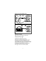
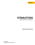
5700A/5720A
Series II Multi-Function Calibrator
Operator Guide
PN 601648
May 1996
© 1996 Fluke Corporation, Inc.
All rights reserved. Printed in U.S.A.
®
Contents
What is in this Guide? ................................ 2
Safety Summary ......................................... 2
P Fuse and Line Voltage .......................... 4
Basic Operation.......................................... 5
A Short Calibration Exercise ....................... 5
Warming up the Calibrator ..................... 5
Exercise: Running dc Zero Calibration ........ 6
Connecting a Meter................................ 6
Applying a dc Voltage ............................ 7
Checking the Calibrator Uncertainty ....... 7
Exercise: Activating Error Mode ............. 8
Checking the Meter’s Higher and Lower
Ranges ..................................... 8
Exercise: Applying an ac Voltage ........... 9
Front Panel Features.................................. 10
Output Display (Left Side) ...................... 10
Control Display (Right Side) ................... 10
Display Screen Saver............................. 11
Front Panel Keys ................................... 12
Front Panel Connectors ......................... 21
Rear Panel Features .................................. 23
Rear Panel Connectors .......................... 23
Switches and Fuse Holder...................... 26
Cable Recommendations............................ 27
Connecting to a UUT (Unit Under Test) ...... 28
Using Error Mode ....................................... 35
Operating in Remote .................................. 37
RS-232-C Interface Parameters.................. 38
1
What is in this Guide?
The Operator Guide begins with safety
information, a short meter calibration exercise for
new users, then continues with a condensation of
information from the Operator Manual. For
complete information about the Calibrator’s
features, functions, and operating procedures,
refer to the Operator Manual.
Safety Summary
Warning
[
Lethal voltage may be present on the
terminals. Observe all safety
precautions in this guide.
To avoid electrical shock hazard, the operator
should not electrically contact the OUTPUT HI or
SENSE HI binding posts. During operation, lethal
voltages of up to 1100V ac or dc may be present
on these terminals.
Whenever possible, keep one hand away from the
equipment to reduce the hazard of current flowing
through vital organs of the body.
Symbols Marked on Equipment
[
Q
P
Warning - Risk of electric shock.
Ground Protective ground (earth) terminal.
Attention Refer to the manual for
information about this feature. This symbol
appears on the rear panel ground terminal
and by the fuse holder.
Use the Proper Fuse
To avoid fire hazard, use only the fuse specified
on the line voltage selection switch label.
2
Safety Summary (cont.)
[Grounding the Calibrator
The Calibrator is a Safety Class I (grounded
enclosure) instrument. The enclosure is grounded
through the grounding conductor of the power
cord. To avoid electrical shock, plug the power
cord into a properly wired earth grounded
receptacle before making any connections to the
Calibrator terminals. A protective ground
connection by way of the grounding conductor in
the power cord is essential for safe operation.
[Do Not Remove the Cover
To avoid personal injury, do not remove the
Calibrator cover. Do not operate the Calibrator
without the cover properly installed. There are no
user-serviceable parts inside the Calibrator, so
there is no need to ever remove the cover.
3
P Fuse and Line Voltage
The correct fuse type for each voltage selection is
indicated on the rear panel as shown in the
following figure.
CAUTION FOR FIRE PROTECTION REPLACE ONLY
WITH A 250V FUSE OF INDICATED RATING.
VOLTAGE
SELECTION
100V
110V
115V
120V
VOLTAGE
SELECTION
FUSE-F1
S2 S3 S4
200V
220V
230V
240V
T 125A
250V
(SB)
FUSE-F1
S2 S3 S4
T 125A
250V
(SB)
CAUTION FOR FIRE PROTECTION REPLACE ONLY
WITH A 250V FUSE OF INDICATED RATING.
VOLTAGE
SELECTION
100V
110V
115V
120V
FUSE-F1
S2 S3 S4
T 125A
250V
(SB)
VOLTAGE
SELECTION
200V
220V
230V
240V
FUSE-F1
S2 S3 S4
T 125A
250V
(SB)
Line Power Label and Switch Locations
4
Basic Operation
To set the output, simply press the following
sequence of keys to select an output function and
amplitude:
[numeric keys] [multiplier] [function] E O
For example, to set the output to 10 mV dc, press:
1 0 m V E O
To set an ac output, press the following additional
keys:
[numeric keys] [multiplier] H E
For example, to change the present 10 mV dc to
10 mV ac @ 1.8 kHz, press:
1 . 8 K H E
To change the output back to dc, press:
0 H E
or
+ E
A Short Calibration Exercise
If you are not familiar with the Calibrator, you will
find that the following exercise quickly teaches you
some important front panel operations.
Warming up the Calibrator
When you first turn the Calibrator on, you should
let it warm up for 30 minutes. This ensures that the
Calibrator meets or exceeds its specifications.
5
Exercise: Running dc Zero Calibration
DC Zero is a brief internal process that removes
offset errors. The specifications require that you
run dc Zero at least every 30 days.
To run dc Zero, press the following sequence of
softkeys:
Setup Menus Cal Zero
Press any key, then press P twice to return to
normal operation.
Connecting a Meter
Typical connections for handheld and benchtop
meters are shown on the next page. The diagrams
show the use of Fluke Model 5440-7002 Low
Thermal Cables. Other types of cable may be used
for this exercise. To connect either type of meter,
proceed as follows:
1.
Verify that the Calibrator is on, and is in
standby mode (STANDBY indicator lit). If the
Calibrator is not in standby, press r.
2.
Set the meter to the lowest range that reads
10V dc.
3.
Connect the shield lead (if your cables are
shielded) to V GUARD on the Calibrator.
4.
Verify that both X and x are off. Press
them if they are lit.
5.
Connect the meter input LO to the Calibrator
OUTPUT LO.
6.
Connect the meter input HI to the Calibrator
OUTPUT HI.
6
Exercise: Connecting a Meter (cont.)
DMM
EX SNS
: OFF
EX GRD
Calibrator
: OFF
OUTPUT SENSE
VΩA
VΩ
HI
HI WIDEBAND
LO
LO
HI
10A V Ω
AUX
CURRENT
300mA
COM
GUARD GROUND
NC
EX SNS
: OFF
EX GRD
: OFF
Calibrator
OUTPUT SENSE
VΩA
VΩ
WIDEBAND
HI
HI
INPUT
LO
LO
HI
DMM
AUX GUARDGROUND
CURRENT
NC
Applying a dc Voltage
Apply 10V dc to the meter by pressing the
following sequence of keys:
10VEO
Checking the Calibrator Uncertainty
Press s. The total uncertainty for the 10V you
are applying to the meter is displayed on the
Control Display (the large dot-matrix display on the
right side of the front panel). This number depends
on the setting of the calibration cycle and
specification confidence level in a setup menu.
Press P to clear the uncertainty display.
7
Exercise: Activating Error Mode
Chances are the meter reads something other than
exactly 10V. To quickly check the error of the
meter, turn the rotary knob to obtain a meter
reading of exactly 10V, and read the error off the
Control Display.
Turning the knob is all it takes to activate error
mode. When you turn the knob, the least
significant digit is highlighted. This digit changes
as you turn the knob. To change a higher order
digit, thereby speeding up the adjustment rate,
press <.
The error on the Control Display is a combination
of offset, scale, and linearity errors. You can view
component parts of the error by pressing o and
S.
Checking the Meter’s Higher and Lower Ranges
To check the meter error at 100V dc, first set the
meter range (if applicable) to the lowest range that
reads 100V. Press Y O. This sets a new
reference equal to ten times the previous
reference of 10V dc. (Pressing O was necessary
because the Calibrator goes into standby when it
crosses the safety threshold from below 22V to
over 22V.) Turn the rotary knob to re-activate error
mode and determine the meter error at 100V.
Now press Z Z. Set the meter range switch (if
applicable) to the lowest range that reads 1V.
To end the error mode session, press E.
This recalls the reference value and exits error
mode.
Press r to set the output to 0 mV dc in standby.
8
Exercise: Applying an ac Voltage
There is no “ac mode” switch on the Calibrator.
You change a dc output to ac by entering a
frequency through the keypad and pressing
E.
To test the meter at 10V at 1 kHz, set the meter to
read 10V ac, press 1 0 V, then 1 K
HEO. Adjust the rotary knob for a
reading on the meter of exactly 10V.
To test the meter’s flatness, press a. The 0.1 Hz
digit is highlighted. Press < four times. Turn the
knob to change the 1 kHz digit until the Calibrator
is set to 10 kHz. Press a and turn the knob
again to check the meter’s accuracy at 10 kHz.
Each time you change the frequency, you need to
wait for the Calibrator output to settle (the “u”
annunciator will go out).
This ends the front panel exercise. To zero the
output and go to standby, press r.
9
Front Panel Features
Following is a brief description of the Calibrator’s
front panel features.
Output Display (Left Side)
Shows output amplitude and frequency. The top
line shows the active output value in up to eight
digits, plus a polarity sign. The bottom line shows
output frequency in five digits. Annunciators below
the amplitude line on the output display indicate
the following active conditions:
OPERATE
Lit when an output is active at the
binding posts or auxiliary amplifier.
STANDBY
Lit when the Calibrator is in standby.
ADDR
Lit when the Calibrator is addressed
over the IEEE-488 interface.
ØLCK
Lit when the Calibrator output is
phase locked to a signal at the rear
panel PHASE LOCK connector.
ØSHF
Lit when the Calibrator output has a
programmed phase difference with a
signal at the real panel VARIABLE
PHASE OUT connector.
u
(Unsettled) Lights when the output is
changed, and remains lit until the
output settles to within specification.
Control Display (Right Side)
Shows data entries, UUT error adjustments,
softkey labels, and other prompts and messages.
Each softkey label identifies the functions of the
softkey that appears directly below it. All of the
softkey labels that appear on the display at once
are referred to as a menu. When you access the
function provided through the softkeys, you open
up other menus, containing new softkey labels.
10
Display Screen Saver
Both the Output and Control displays blank
automatically after 30 minutes of inactivity, unless
the Calibrator is in one of the operating states that
overrides the screen saver.
If the screen saver has activated, you can restore
the display by pressing C. Pressing another key
or turning the knob restores the display and
performs the command sent by the key or knob.
The screen saver does not operate:
•
if any part of the Setup menu is displayed.
•
during remote operation.
•
during calibration or diagnostics.
•
when an error message is displayed.
11
Front Panel Keys
O
Toggles the Calibrator between operate and
standby modes. In standby mode, the OUTPUT
binding posts are internally disconnected from the
Calibrator. The Calibrator powers up in standby
mode.
The Calibrator automatically switches to standby
mode when:
•
r is pressed.
•
the Calibrator is sourcing an ac or dc voltage
below 22V, and a voltage greater than 22V is
selected.
•
the output function is changed, e.g., from dc
current to ac current.
•
the output location is changed.
The Calibrator does not switch to standby when
the voltage is switched from any ac or dc voltage
to an ac or dc voltage less than 22V.
12
Front Panel Keys (cont.)
X
Opens and closes an internal connection between
the SENSE and OUTPUT binding posts. The
Calibrator powers up with these two binding posts
connected internally (the SENSE binding posts are
open circuited), and the X indicator off. Toggling
X on (so it lights) disconnects the sense lines
from the OUTPUT binding posts.
External sensing should be used in the following
function under the stated conditions.
•
In the dc voltage function when the UUT
draws enough current to produce a significant
voltage drop in the cables.
•
In the resistance function when the UUT has a
four-wire input and the Calibrator is set to 100
kΩ or less.
•
External sensing can also be used in the twowire ohms function to activate two-wire
compensation circuitry to the UUT terminals.
13
Front Panel Keys (cont.)
x
Opens and closes an internal connection between
the V GUARD (voltage guard) and OUTPUT LO.
The Calibrator powers up with the V GUARD
internally connected to OUTPUT LO and the x
indicator off. Toggling x on (so it lights)
disconnects OUTPUT LO from the V GUARD.
The V GUARD binding post provides an external
connection point for the voltage internal guard. For
a UUT with ungrounded inputs, the V GUARD
should be connected to LO internally. (The EX
GRD key is toggled off.) For a UUT with a
grounded input, the GUARD may be externally
connected to the grounded UUT input. (The EX
GRD key is toggled on.)
w
Enables and disables the -03 Wideband AC option
and sets the Calibrator to standby mode. When
enabled, the ac voltage output over the range of
10 Hz to 30 MHz is available at the front panel
WIDEBAND connector. The wideband function is
disabled whenever w is toggled off, or when
another function (such as current) is selected.
14
Front Panel Keys (cont.)
B
Enables or disables output from an amplifier, when
it would not otherwise be automatically selected.
Sets the Calibrator to standby if this selection
moves the output location.
When available, an amplifier is automatically
selected for output settings that exceed Calibrator
capabilities, but fall within the limits of the selected
amplifier. The B key is only needed to activate
an amplifier for an output setting that is available
from either the Calibrator or from the amplifier.
This allows you to take advantage of amplifier
capabilities other than extended range (i.e. higher
compliance voltage).
For both voltage and current, the amplifier is
assumed to be a 5725A unless another model is
designated in the Setup menus.
P
Aborts the current operation of the Calibrator and
recalls the previous menu. Some menus display a
more specific label for this key, such as “DONE
setting up.”
Softkeys
u
The functions of the five unlabeled softkeys are
provided through each menu in the Control
Display, with each function located directly above
the softkey that activates that function. Many of
these functions access new menus that contain a
new set of functions for the softkeys, providing
access to many capabilities and configuration
options through the menu tree.
POWER switch
Turns the power on and off.
15
Front Panel Keys (cont.)
<a>
These keys are the output adjustment controls. If
any of these keys are pressed, or if the knob is
turned, a digit on the Output Display becomes
highlighted. Turning the knob adjusts the output
value. An error display appears on the Control
Display, showing the difference between the
original (reference) output and the new (adjusted)
output.
The < and > keys move the highlight to the
digit you wish to change. In the ac functions, the
a key allows you to move amongst voltage,
current, and frequency. In practice, for voltage and
current outputs, the knob and arrow keys are used
to adjust output until the UUT reads correctly. The
error display shows the UUT deviation from the
reference.
r
During local operation, pressing r aborts the
current operating state of the Calibrator and
returns the Calibrator to the power-up default
state. (This key is not effective during remote
operation.)
S
Identifies a UUT full-scale endpoint for checking
linearity, and does not change the output. If the
output was adjusted with the rotary knob,
subsequent keyed-in output values are multiplied
by a scale factor. Scaling is deactivated by
pressing S again, or by selecting another
function. Scaling is not available for resistance
outputs.
16
Front Panel Keys (cont.)
L
Calls up a menu that allows you to specify limits
beyond which the Calibrator will not operate. This
can be used to set limits that protect both
operators and equipment.
Z
Changes the output to one tenth the reference
value (which is not necessarily the same as the
present output value). The value only changes if
the new value is within performance limits.
Y
Changes the output to ten times the reference
value (which is not necessarily the same as the
present output value). The value only changes if
the new value is within performance limits. This
key sets the Calibrator to standby if this change is
made from a value less than 22V to one that is
greater than or equal to 22V.
s
Causes the Calibrator to compute and display its
uncertainty for the present output setting for the
calibration interval and specification confidence
level selected in the setup menus.
o
Identifies a UUT zero-scale endpoint and does not
change the output. Subsequent keyed-in output
values have the offset value (the Calibrator output
value when o was pressed) added to them.
Offset mode is deactivated by pressing o again,
or by selecting another function. Offsets are
available for dc outputs only.
17
Front Panel Keys (cont.)
C
Clears a partially completed keypad entry from the
Control Display, or clears an error message that
required acknowledgment, If there is a partially
completed entry when C is pressed, the output is
unaffected.
N
This key is only active during error mode
operation. It establishes the present output value
as a new reference for meter error computation.
D
When in the ac volts, or wideband function, and if
no entry is in progress, the D key shows the
equivalent dBm output on the Control Display. For
the ac voltage function, dBm is calculated for a
600Ω load. (For ac outputs less than 220 mV, the
Calibrator output impedance is always
50Ω because the output is resistively divided.) For
the wideband function, dBm is calculated for a
50Ω resistive termination at the end of a three-foot
50Ω coaxial cable.
Note
The formula to compute dBm is:
dBm = 10 log (power in mW)
Examples:
For 3.0V into a 600Ω load:
dBm = 10 log (15.000) = 11.7609 dBm
for 3.0V into a 50Ω load:
dBm = 10 log (180.000) = 22.5527 dBm
18
Front Panel Keys (cont.)
E
Loads a newly keyed-in output value showing on
the Control Display into the Calibrator. If you press
E without identifying the units for the entry,
the Calibrator keeps the units (except Hz) that
were last used. This allows you to alter values for
a function without keying in the units every time.
The multipliers are not retained, for example, you
can enter 1 mV, and then later simply enter 10 to
obtain 10V.
In addition to these functions, the E key
recalls the currently programmed reference value
during error mode operation.
D V A Q H
(Output Function Keys)
These keys select the output function as follows:
D
V
A
Q
H
Decibels relative to 1 mW
Voltage
Current
Resistance
Frequency
When a value, then H are selected, the
Calibrator automatically switches to ac. To change
back to dc, enter 0 H or enter a signed (+ or amplitude).
U m K M
(Multiplier Keys)
These keys select output value multipliers. For
example, if you enter 33, then m, then V, then
ENTER, the Calibrator output value is 33 mV.
U
m
K
M
-6
micro (10 or 0.000001)
-3
milli (10 or 0.001
3
kilo (10 or 1000)
6
Mega(10 or 1,000,000)
19
Front Panel Keys (cont.)
0 - 9 (Numeric Keypad)
Used to enter the digits of the output amplitude
and frequency, as well as other data such as the
time and date. The proper sequence for entering a
value is to enter the digits, then any necessary
multipliers, an output function key, then E.
For example, to obtain an output of 20 mV, you
would press the following sequence of keys:
2 0 m V E. The . key is
available for decimal places.
+
If the output function is dc voltage, current, ac
voltage entered in dBm, or a wideband output
entered in dBm, pressing + E toggles the
polarity of the output. If the output function is ac
voltage or current, pressing + E changes
the output to dc.
20
Front Panel Connectors
WIDEBAND Connector
A type “N” connector that provides a connection
point for output from the -03 Wideband AC option.
Wideband output specifications are stated for
output levels present at the end of its three-foot
50Ω coaxial cable terminated into a 50Ω purely
resistive load. The connector shell is connected to
chassis ground.
GND Binding Post
If the Calibrator is the location of the ground
reference point in a system, the GND binding post
can be used for connecting other instruments to
earth ground. (The chassis is normally connected
to earth ground through the three-conductor line
cord instead of through the earth ground binding
post.)
V GUARD Binding Post
Provides an external connection point for the
internal voltage guard. For a UUT with floating
(ungrounded) inputs, the C GUARD should be
connected to LO internally (x key toggled off).
For a UUT with a grounded input, the V GUARD
must be externally connected to the grounded UUT
input (x key toggled on). The maximum
allowable potential between the V GUARD
connector and chassis ground is 20V peak.
21
Front Panel Connectors (cont.)
SENSE Binding Posts
Used in the resistance and voltage functions for
sensing at the UUT after you have selected
external sense by toggling the X key on, or by
remote command.
External sensing should be used in the dc voltage
function when the UUT draws enough current to
produce a significant voltage drop in the cables,
and in the resistance function when the UUT has a
four-wire ohms input and the Calibrator is set to
100 kΩ or less. External sensing can also be used
in the two-wire ohms function to allow the two-wire
compensation circuitry to the UUT terminals. Refer
to the connection diagrams for examples of usage.
OUTPUT Binding Posts
Provide connection points for ac and dc current
and voltage output, as well as for resistance. The
function of each OUTPUT binding post is defined
below:
LO
The common binding post for all
output functions including Calibrator
amplified voltage output, but not for
Option -03 Wideband AC or auxiliary
amplifier output.
HI
The active binding post for all output
functions, including 5725A amplified
voltage output; does not include
Option -03 Wideband AC or auxiliary
amplifier output.
AUX
CURRENT
OUTPUT
An optional active binding post for
current. This output is convenient for
calibrating UUTs that have a
separate current input terminal.
22
Rear Panel Features
The following list provides descriptions of the
connectors and switches on the Calibrator’s rear
panel.
Rear Panel Connectors
5725A AMPLIFIER Connector
Provides the analog and digital interface for the
Fluke 5725A Amplifier.
5205A AMPLIFIER Connector
Provides the analog and control interface for either
the Fluke 5205A or 5215A Precision Power
Amplifier.
5220A AMPLIFIER Connector
Provides the analog and control interface for the
Fluke 5220A Transconductance Amplifier.
VARIABLE PHASE OUT BNC Connector
Provides access to a variable-phase nominal 2.5V
rms sine wave signal. The phase of this signal can
be adjusted using the arrow keys and rotary knob
(or by remote commands) to lead or lag the main
Calibrator output signal by up to 180°. The
connector shell is not connected directly to chassis
ground; it is connected internally to the OUTPUT
LO binding post. The maximum allowable potential
between the connector shell and chassis ground is
20V peak.
23
Rear Panel Connectors (cont.)
PHASE LOCK IN BNC Connector
Provides the input for an external signal onto
which the Calibrator can be phase locked (1V to
10V rms, 10 kΩ input impedance). The connector
shell is not connected directly to chassis ground; it
is connected internally to the OUTPUT LO binding
post. The maximum allowable potential between
the connector shell and chassis ground is 20V
peak.
IEEE-488 CONNECTOR
This is a standard interface connector for
operating the Calibrator in remote control as either
a Talker or a Listener of the IEEE-488 Bus.
RS 232C Connector
A male (DTE) serial port connector for transmitting
internal calibration constant data to a printer,
monitor, or host computer. This connector is also
used for remote control of the Calibrator.
24
Rear Panel Connectors (cont.)
The OUTPUT, SENSE, and V GUARD binding
posts on the rear panel are alternative connections
to the UUT. An internal cable enables either the
front or rear binding posts. The procedure to
disable the front panel binding posts and enable
the rear panel binding posts involves opening the
cover of the Calibrator, which should only be done
by authorized service personnel.
The I GUARD binding post provides an external
connection point for the internal current guard. The
current guard is used when the Calibrator is
supplying low-level ac current through a long cable
to remove errors introduced by leakage through
the cable capacitance.
Refer to the connection diagrams for examples of
usage.
AUX CURRENT OUTPUT
This output is not available on the rear panel
binding posts.
CHASSIS GROUND Binding Post
A binding post that is internally grounded to the
chassis. If the Calibrator is the location of the
ground reference point in a system, this binding
post can be used for connecting other instruments
to earth ground. (The chassis is normally
connected to earth ground through the threeconductor line cord instead of through the earth
ground binding post.)
25
Switches and Fuse Holder
CALIBRATION SWITCH
A slide switch that enables and disables the
capability to write to nonvolatile memory. This
switch is used for recording and then storing
calibration constants, dates, and parameter
settings. When this switch is in the ENABLE
position, you can write to memory; when in the
NORMAL position, the data in the memory is
protected from being overwritten. The switch is
recessed in order to allow the metrologist to cover
it with a calibration sticker to guarantee calibrator
integrity.
F1 Fuse Holder
This holds the line power fuse. See “Fuse and Line
Voltage” at the beginning of this guide for the
location of the correct ratings.
Line Voltage Selection Switches
Select the operating line voltage. See “Fuse and
Line Voltage” at the beginning of this guide for the
location of the label that shows the correct ratings.
26
Cable Recommendations
Output Function
DC Voltage
AC Voltage ≤10 kHz
Cable Recommendations
Low Thermal EMF Test Leads
(5440A-7002) or twisted shielded pair
AC Current ≤2A, ≤10
kHz
DC Current ≤2A
Resistance
AC Voltage > 10 kHz
SENSE/GUARD: Triaxial cable or
Twinax (e.g., Alpha 2829/2).
OUTPUT: Coaxial
Or: SENSE: Coaxial, OUTPUT:
Coaxial GUARD Lead: Separate wire
AC Current with Guard
Triaxial cable
Wideband AC
3 feet (1m) 50Ω coaxial cable with
Type “N” male connector supplied
with the option. A 50Ω feedthrough
terminator is also supplied for
connecting to meters with impedance
higher than 50Ω.
Voltage-Boosted
Output, 5205A or 5215A
Use the cable supplied with the
amplifier.
Voltage-Boosted
Output, 5725A
Low Thermal EMF Test Leads
(5440A-7002). (Output is at the
Calibrator front panel.)
Current-Boosted Output,
5725A, 5220A
16-gauge or heavier twisted-pair
insulated wire, as short as possible to
minimize resistance and inductance.
(Output is at the amplifier terminals.)
27
Connecting to a UUT (Unit Under Test)
A.
EX SNS
: OFF
EX GRD
: OFF
Calibrator
UUT
INPUT
OUTPUT SENSE
VΩ A
VΩ
SENSE
Ω4-WIRE
HI
HI
LO
LO
A
HI
WIDEBAND
HI
LO
LO
HI
GUARD
AUX
GUARD GROUND
CURRENT
B.
EX SNS
: ON
EX SNS
: ON
UUT
Calibrator
INPUT
DC
SHIELDED TWISTED
PAIR
AC
OUTPUT SENSE
VΩ A
VΩ
WIDEBAND
HI
HI
LO
LO
HI
SHIELDED TWISTED
PAIR
C.
EX SNS
: OFF
: ON
Calibrator
UUT
HI
EX GRD
AUX GUARD GROUND
CURRENT
OUTPUT SENSE
VΩ A
VΩ
HI
WIDEBAND
HI
LO
LO
LO
HI
AUX GUARD GROUND
CURRENT
DC Voltage, AC Voltage ≤10 kHz
28
Connecting to a UUT (cont.)
A.
EX SNS
: ON
EX GRD
: OFF
UUT
Calibrator
TRIAXIAL CABLE
INPUT
OUTPUT SENSE
VΩ A
VΩ
SENSE
Ω4-WIRE
HI
HI
LO
LO
HI
WIDEBAND
HI
LO
LO
TRIAXIAL CABLE
A
HI
GUARD
B.
AUX V-GUARD GROUND
CURRENT
EX SNS
: OFF
EX GRD
: OFF
Calibrator
UUT
INPUT
SENSE
Ω4-WIRE
HI
HI
LO
LO
TRIAXIAL CABLE
OUTPUT SENSE
VΩ A
VΩ
HI
LO
A
WIDEBAND
HI
LO
HI
GUARD
AUX V-GUARD GROUND
CURRENT
NOTE
Keep the SENSE leads as short as possible.
Be careful not to exceed the capacitive load limit of
1000 pF up to 220V, 600 pF 220 to 1100V. (1000 pF
with 5725A Amplifier.)
AC Voltage >10 kHz
29
Connecting to a UUT (cont.)
A.
EX SNS
: OFF
EX GRD
Calibrator (FRONT)
UUT
INPUT
: OFF
OUTPUT SENSE
VΩ A
VΩ
SENSE
Ω4-WIRE
HI
HI
LO
LO
A
HI
WIDEBAND
HI
LO
LO
HI
GUARD
B.
AUX GUARDGROUND
CURRENT
EX SNS
: OFF
EX GRD
: OFF
Calibrator (REAR)
UUT
INPUT
SENSE
Ω4-WIRE
HI
HI
LO
LO
A
GUARD
OUTPUT SENSE
VΩ A
VΩ
TRIAXIAL CABLE
HI
HI
LO
LO
NC
I-GUARD
AC Current ≤2A
30
V-GUARD
Connecting to a UUT (cont.)
A.
EX SNS
: ON
EX GRD
: OFF
2-WIRE
COMP
OFF
UUT
Calibrator
INPUT ΩSENSE
4-WIRE
OUTPUT SENSE
VΩ
V ΩA
HI
HI
LO
LO
A
HI
WIDEBAND
HI
LO
LO
HI
GUARD
AUX GUARD GROUND
CURRENT
SENSE
SOURCE
UUT
Calibrator
SOURCE
SENSE
B.
EX SNS
: OFF
EX GRD
: OFF
UUT
2-WIRE
COMP
OFF
Calibrator
OUTPUTSENSE
VΩ A
VΩ
HI
WIDEBAND
HI
LO
LO
HI
10A V Ω
300mA
COM
AUX
GUARD GROUND
CURRENT
NC
UUT
Calibrator
Resistance
31
Connecting to a UUT (cont.)
C.
: ON
EX SNS
EX GRD
2-WIRE
COMP
ON
: OFF
UUT
Calibrator
OUTPUT SENSE
VΩ A
VΩ
WIDEBAND
HI
HI
LO
LO
HI
10A VΩ
AUX GUARD GROUND
CURRENT
NC
COM
300mA
NC
Caution
Use Connections With Exposed Plug Tips
For The Ohms Function Only.
COMP
UUT
Calibrator
COMP
D.
EX SNS
: OFF
EX GRD
: OFF
UUT
2-WIRE
COMP
ON
Calibrator
OUTPUT SENSE
VΩA
VΩ
WIDEBAND
HI
HI
LO
LO
HI
10A VΩ
COM
300mA
AUX GUARD GROUND
CURRENT
NC
COMP
UUT
Calibrator
COMP
Resistance (cont.)
32
Connecting to a UUT (cont.)
50Ω Feedthrough Terminator
Supplied With Option -03
Calibrator
OUTPUT SENSE
VΩ
V ΩA
WIDEBAND
HI
HI
LO
LO
HI
AUX GUARD GROUND
CURRENT
Cable Supplied With
Option -03
Cable Supplied With
Option -03
NOTE
For wideband meters with higher than 50Ω input impedance,
use the 50Ω feedthrough terminator at the meter connection
end. For all wideband applications, take care to achieve a
good 50Ω impedance match (use cable and connectors with
a characteristic input impedance of 50Ω).
Wideband AC Voltage Output
(Option -03)
33
Connecting to a UUT (cont.)
5725A
HI
LO
UUT
INPUT
SENSE
Ω 4-WIRE
HI
HI
LO
LO
A
GUARD
5725A Amplified Current Output
34
Using Error Mode
Activate error mode by turning the rotary knob,
pressing an arrow key, or pressing a. When you
enter error mode, the starting value is the
reference from which errors are computed. A new
reference is established when you exit and reenter
error mode. The following table lists the actions
that cause the Calibrator to exit error mode.
35
Using Error Mode (cont.)
Keys
Action
E
Returns to the previous reference
value.
+, then E
Establishes a new reference.
A keypad entry, then
Establishes a new reference.
E
N
Establishes the present output as a
new reference.
Y
Sets the Calibrator to ten times the
reference value and establishes a new
reference.
Z
Sets the Calibrator to one-tenth the
reference value and establishes a new
reference.
o
Identifies the present output as a zeroscale endpoint for scaling, and
establishes 0.0 as the new reference.
S
Identifies the present output as a fullscale endpoint for scaling and causes
the display to show scale error.
r
Returns to the power-up state.
The “Setup Menus”
softkey
Opens the setup menu.
36
Operating in Remote
To operate the Calibrator remotely, proceed as
follows:
1.
Turn off the Calibrator power.
2.
Connect a remote interface to either the RS232C or IEEE-488 connector on the Calibrator
rear panel.
3.
Turn on the Calibrator power.
4.
Choose the correct remote parameters using
the softkey menus:
a.
Setup Menus Instmt Setup Remote Port
Setup
b.
Select Remote Port type (GPIB = IEEE488), Remote lang (NORMAL or emulation
mode)
c.
Select either GPIB Port Setup or RS-232
Port Setup.
d.
If GPIB: select the address.
e.
If RS-232: select the parameters in the
next table.
37
RS-232-C Interface Parameters
Parameter
Choices
Default Setting
Data Bits
7 or 8
8
Stop Bits
1 or 2
1
Flow Control
Ctrl S/Ctrl Q
(XON/XOFF), RTS,
or none
Ctrl S/Ctrl Q
Parity Checking
Odd, even, or none
none
Baud Rate
110,300,600,1200,
2400,4800,9600, or
19200
9600
Time-out Period
0 to 30 seconds
0 (no time-out)
EOL (End of Line)
CR, LF, or CR LF
CR LF
EOF (End of File)
Any two ASCII
characters
no characters
38