1
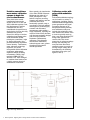
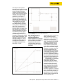
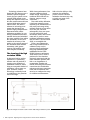
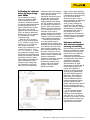
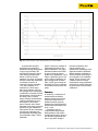
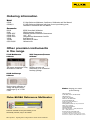
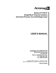
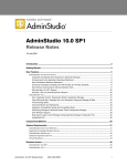
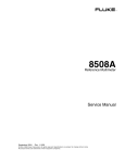
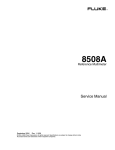
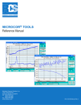
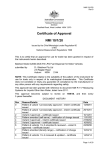
Migrating from dc voltage dividers to
modern reference multimeters
Application Note
Introduction
Until the late 1980’s electrical
calibration systems used to
compare primary and secondary
voltages and resistance standards
consisted of several different
components. Systems like the
Fluke 7105A and the Datron
4900 were the backbone of the
majority of electrical calibration
laboratories the world over.
These systems were specifically
combined to provide a traceable
source, according to a set of
measurement parameters. For
example, the Fluke 7105A
system comprised the following
instruments:
• Fluke 720A Kelvin Varley
Divider
• Fluke 750A Reference Divider
• Fluke 335A DC Voltage
Standard
• Fluke 721A Lead Compensator
• 845AR High Impedance Null
Detectors
Similarly, a comparable system
from Datron (later acquired by
Fluke in January 2000) was
also available. Much like the
Fluke 7105A, the Datron 4900
system included:
• 4901 Calibration Bridge/Lead
Compensator
• 4902 DC Voltage Divider
• 4903 DC Calibration Unit
• 4904 Standard Cell Buffer
However, as new innovative
technology and techniques
were introduced, both the
7105A and 4900 calibration
systems were soon replaced. So
what caused their extinction?
Fig. 1 Fluke 7105A calibration system
Fig. 2 Datron 4900 calibration system
From the Fluke Digital Library @ www.fluke.com/library
Evolution caused these
more mature calibration
systems to begin the
road to obsolescence
There have been several
contributing factors to the
demise of the old 7105A and
4900 calibration systems. First,
the development of artifact
calibration has not only
consolidated the system into a
single device, but has also fully
automated the process.
Second, the design of modern
calibrators incorporates pulse
width modulation (PWM)
techniques to maintain a ‘right
by design philosophy’ that
provides extremely repeatable
source linearity. Furthermore,
zener reference technology
improved, and, when
incorporated within calibration
equipment, subsequently
improved stability reducing
uncertainties. Finally, high
resolution DMMs like the
Wavetek 1281 then managed
to combine these features into
a highly accurate electrical
measurement instrument.
More recently, the introduction
of the Fluke 8508A Reference
Multimeter has taken all of
these philosophies a step
further to improve accuracy,
linearity and stability, and has
combined them into a
functionally versatile, easy to
use solution. This has enabled
metrologists to perform highly
accurate and automated
measurement tasks within a
single instrument, replacing the
need for Kelvin-Varley dividers,
null detectors, resistance bridges
and even PRT (Platinum
Resistance Thermometer)
calibrators. This ultimately
means faster calibrations,
reduced support costs, greater
throughput and minimal
manual operations.
Fig. 3 Two stage PWM circuit
2
Fluke Corporation Migrating from dc voltage dividers to modern reference multimeters
Calibrators evolve with
pulse width modulation
(PWM)
Pulse width modulation topology
can be found in a variety of
applications, including various
telecommunications applications,
power generation and signal
processing. Because of its
exceptional linearity benefits,
most calibrators today now
include this technique in their
own internal ratio divider. Such
a circuit is typically made up
from a two stage switching FET
design with synchronous
control clock. This circuit
passes the dc reference voltage
through the switching FET
array and then filters their
summed outputs to provide an
average output voltage that is
determined by the resulting
waveform’s duty cycle. (see
figures 3 and 4).
The output is then passed
through a multi-stage, low pass
filter network, capable of eliminating all ripple and noise
content, and thus providing a
highly stable and linear output
voltage. The output voltage
can be expressed using the
formula: VO = VIN x X/n
The ratio divider criterion in a
calibrator is consequently set
by the frequency of the control
clock driving the two FETs.
As with any ratio divider,
the PWM technique operates
on the basis of ‘dimensionless’
ratio. That is, there are no
absolute quantities involved
that are subject to change over
time offering very repeatable
linearity dependent only upon
an extremely reliable digital
clocking waveform. To further
maintain high confidence,
linearity is subsequently verified
during artifact calibration. This
approach compares the same
two fixed voltages, V1 and V2,
on different ranges. Figure 5
illustrates this comparison. If
the PWM is perfectly linear,
then N4/N3 = N2/N1.
Fig. 5 Converter linearity verification
Fig. 4 A representation of the output voltage prior
to filtering
The development of
artifact calibration
Artifact calibration is a process
where calibrators automatically
perform internal ratiometric
comparisons and store the
correction data relative to a
few precise external artifact
standards.
Traditionally these comparisons
were performed using an
assortment of ratio measuring
equipment to achieve this.
However, over the last twenty
years, instruments with artifact
calibration capability have all
but eliminated many of these
labor-intensive measurement
tasks. Many traditional manual
operations to establish voltage,
resistance or current ratios can
now be accomplished automatically within the instrument,
consequently providing consistent and efficient calibrations,
as well as significantly reducing
the costs previously associated
with higher labor intensity and
a larger equipment inventory.
Fundamentally, an instrument
with artifact calibration
capabilities will first transfer
and then reference to a set of
external artifact voltage and
resistance standards. Having
been transferred, this internal
voltage reference can then be
configured to appear as if it
had been applied to an internal
array of comparable instruments
like a Kelvin-Varley divider, a
null detector or even a decade
divider, though in practice this
is not really the case.
Fluke Corporation Migrating from dc voltage dividers to modern reference multimeters
3
Technology advances have
shrunk the null detector onto a
miniature hybrid integrated
circuit, the ratio system is now
a single PWM printed circuit
board, and improved lower cost
thin film resistor networks have
replaced bulky wire-wound
resistor ratios. This kind of
advance in technology now
means that designers can
produce highly comprehensive
instruments with artifact
calibration capability. So now,
having eliminated these extra
external devices and mimicked
the same capability from within
the instrument, we can now
transfer the accuracy of the
artifact to the various ranges of
the instrument with minimal
uncertainty, with greater
accuracy and stability, and
with complete traceability.
The dawning of the high
resolution DMMs
As discussed earlier, artifact
calibration is a particularly
efficient and easy method of
carrying out a multitude of
calibrations. However, while
being an acceptable method of
calibration, it does come at a
price. Therefore, artifact
technology is normally found
on calibrators at the premium
end of the range.
While lower performance, less
accurate calibrators forego
artifact design, adopting more
traditional direct function-tofunction, range-to-range
verification.
Even with artifact calibration,
it has been generally recommended by all manufacturers to
fully verify each range using
external methods at least twice
in its first year, and then
subsequently every two years.
It is this reason that many
laboratories would, and in some
cases still do, resort to more
traditional calibration systems,
like the Fluke 7105A or Datron
4900, to accomplish this.
Today, most laboratories
with a large installed base of
calibrators carry out the
process of their verifications
using high resolution digital
multimeters like the Fluke
8508A Reference multimeter.
These meters can be used to
perform all of the functions
previously associated with the
older calibration systems with
little or no degradation of
uncertainties. Another real
benefit with using these meters
comes from the considerable
reduction with inter-connection
leads and the immense time
saved to re-configure the setup
for a different measurement.
Fig. 6 An example of a Fluke 7105A or datron 4900 voltage calibration system
4
Fluke Corporation Migrating from dc voltage dividers to modern reference multimeters
Add to this the ability to fully
automate the calibration
process, and the reference
multimeter becomes very easy
to justify over most of the
traditional systems.
Calibrating the calibrator
before the days of longscale DMMs
The advantages of using a
single high resolution DMM
over the traditional multiinstrument calibration systems
are probably best demonstrated
by firstly describing how a
typical calibration would have
been carried out. Figure 6
illustrates the source calibrator
(UUT), an external divider, null
detector and a 10 V dc reference
in a conventional voltage
calibration setup.
Here the 100 V dc source
(UUT) is being verified against
a 10 V reference, using a ratio
divider of 10:1. In reality the
ratio divider would have
several ‘taps’ calibrated to a set
of definitive ratios i.e. 100:1,
10:1, 1:1 V and 0.1:1 V. Before
any verification of voltage could
take place, the individual ratios
would have first been calibrated
separately so that the given
ratios exactly represented the
source instrument’s output
voltage at each voltage step.
The possibility of drift with
time, due to the temperature
coefficient of the ratio resistors,
meant that this process would
have required a skilled
metrologist who knew how to
perform this operation both
competently and promptly.
Having calibrated the divider,
the UUT calibrator could now
be connected as described in
figure 6. With a null detector
between the ratio divider and
10 V dc reference, the source
calibrator would now be
adjusted until the null detector
indicator displayed zero. (Any
residual error would contribute
to the expanded uncertainty.)
From this brief description,
you can probably begin to
comprehend how complex this
particular measurement process
is. In addition, the lack of any
kind of remote capability, the
time consuming makeup of the
procedure and, above all, the
overall cost of the system, only
serves to further compound the
situation. Nonetheless,
advances in technology, coupled
with the need to make the
methodology simpler, faster,
cheaper and more efficient,
help set a new precedent
within the industry.
Early precision high resolution
DMMs like the Fluke 8505/8506
consolidated the methods used
by all of the test devices
illustrated in figure 6 into a
single instrument, so eliminating
most interconnecting lead
errors, greatly reducing the
overall cost of the calibration
system, but moreover, allowing
full automation of virtually all
measurement tasks. This in
turn liberated the senior
metrologist from this task and
allowed him/her to concentrate
on other important laboratory
responsibilities.
Reference multimeter
with reference standard
accuracy and stability
High resolution precision DMMs
have been available for almost
thirteen years, but since their
launch in the late 1980s the
products have remained
comparable in both performance
and application. Since Fluke’s
acquisition of precision
instrument manufacturer
Wavetek-Datron in 2000,
design teams in the US and UK
have worked together and
pooled their expertise to
produce the best in precision
and long-scale DMM design The Fluke 8508A Reference
Multimeter. The 8508A has
taken many of the leading
Fluke and Wavetek-Datron
patented multimeter designs
and then improved them
further, using the latest state of
the art technology and new
electronic measurement design
techniques.
For the example given in
Figure 6, the Fluke 8508A
eliminates every instrument
other than the 10 V reference.
In essence, the function of both
the ratio divider network and
null detector has now been
replicated into the 8508A.
Fig. 7 An example of the reference multimeter being used to accurately verify
the output of the artifact calibrator to a known voltage reference
Fluke Corporation Migrating from dc voltage dividers to modern reference multimeters
5
Furthermore, all interconnecting leads that existed
between these two instruments
have also been eradicated,
removing the probability of
lead errors and consequently
the need to compensate for
these errors. Having connected
the 10 V reference to the Fluke
8508A’s second input channel
(rear input), the 100 V dc from
the UUT being standardized
can then be applied to the
8508A’s front input channel.
This is typically done as shown
in figure 7. The 8508A
Reference Multimeter has two
input channels that can be
automatically switched to
perform a ratio measurement.
The 10 V reference would be
connected to the 8508A’s rear
input (channel B), with the
UUT’s 100 V dc voltage
connected to the 8508A’s front
input (channel A). In Ratio
mode, the 8508A displays the
ratio of the inputs in the form
F-R (front minus rear), or F/R
(front as a percentage of the
rear), or (F-R)/R (the difference
as a percentage of the rear). In
the example given, the F/R (i.e.
the front as a percentage of the
rear) mode would be used. In
this mode, with the 10 V dc
reference connected to the rear
channel and 100 V connected
to the front channel, the display
would show +10.000 000 %.
This is the ratio of the unknown
100 V to the known 10 V
reference. Note that the reference
multimeter is measuring the
whole voltage for each channel
and is configured to a single dc
voltage range (200 V).
Consequently, the only significant
error contributions to this
measurement are the uncertainty
of the 10 V reference standard,
the noise and differential
linearity of the reference
multimeter and the noise of the
UUT 100 V standard.
6
Typical noise of the reference
multimeter is less than 50 nV
pk/pk (7½ Normal & 8½ Fast
ADC modes) with the differential linearity in 8½ digit mode
being better than 0.1 ppm of
range over a value ranging
from 10 V to 1 V (halve the
typical linearity spec for values
spanning the entire DMM scale
from 0 to 19.99999 V).
Note: the above procedure
assumes that the 10 V dc
reference standard being used
is calibrated and has an
assigned value. The assigned
value is keyed into the 8508A
math memory subsequently
correcting any residual gain
error on the multimeters 20 V
range.
Typical procedure sequence:
1) Select DCV 20 V range
2) Connect low thermal cables
to the 8508A front and rear
terminals (8508A-LEAD).
3) Short the Front A and Rear
B inputs at the cable ends
of the 8508A and perform
zero range function.
4) Remove shorts and connect
calibrator to 8508A front input.
5) Connect 10 V reference
standard (e.g. Fluke 732B)
to 8508A rear input.
6) Configure 8508A, rear input,
rolling average, 16 samples,
8.5 digits, and record reference
reading after initiating a
two-minute delay.
7) Select math mode, deselect
rolling average, enter the
reference standard value
(as recorded in step 6) into
the 8508A “m” variable.
8) Select scan, F/R and allow
two minutes for stabilization.
9) Select Math *m.
10) The 8508A will now
perform the ratio reading,
multiply it by the traceable
reference standard value
and display the UUT
normalized value on the
front display.
11) It is recommended that
after approximately 10
averaged readings have
been recorded, refer back
to step #4 to regain a new
reference point.
Fluke Corporation Migrating from dc voltage dividers to modern reference multimeters
The uncertainty associated
with this measurement is
similar to that which might be
obtained by a skilled metrologist
with a newly calibrated voltage
divider and a null detector. In
addition, the reference multimeter can make this measurement for prolonged periods, as
its linearity does not change
significantly over time.
Uncertainty components.
1) DMM short term stability
when measuring 100 V.
2) DMM short term stability
when measuring 10 V.
3) DMM linearity.
The 8508A specifications detail
the uncertainty for the DMM as:
10 V measured on the 200 V
range to eliminate range
switching using 20 minute
transfer specification = 0.4 ppm
of Reading + 0.1 ppm of range
RSS above result with 100 V
measured on the 200 V range
using similar transfer specification
and the total measurement
uncertainty is approximately
2.5 ppm of Ratio.
The 0.4 ppm of reading
accounts for noise and 0.1 ppm
of range accounts for a
conservative linearity specification.
Therefore as two individual
measurements are being
performed during ratio mode
the transfer specification for
each measurement is RSS’d
together yield a measurement
uncertainty of 2.5 ppm of Ratio
reading. Some additional
uncertainty maybe considered
for the source.
Fig. 8 A typical example of type testing linearity on the Fluke 8508A
A conservative linearity
specification is assigned to
multimeters during development
as part of type testing. The
specification supports a worst
case linearity measurement
which is often at the two
extremes of a range. In practice
this spec is often very conservative,
an example would be to
compare a known (traceable)
10 V with unknown 10 V
standard on a fixed range what is the linearity spec? In
this example there is negligible
contribution to linearity as each
measurement is being made at
the same point in a given
range. Linearity measurements
could be performed on every
multimeter to yield better
specs. However, who should
determine how many points are
measured to gain confidence?
This exercise is time consuming
and requires extremely low
measurement uncertainty often
only achievable using JJ Array
standards.
Figure 8 shows an example of
type testing linearity on the
8508A multimeter. The graph
indicates deviation from ideal
in ppm of range at various
points on the multimeters +20 V
range. A published spec of 0.2
ppm of range is assigned, yet
type testing results in better
than ±0.035 ppm of range as
indicated by the two extremes
of deviation from the ideal linearity.
Precision calibrators once
required divider type
measurement uncertainty now
implement artifact calibration.
Where linearity verification is
involved divider technology is
now internal to the calibrator
design. This is not true of all
calibrators where linearity
measurement using multimeter
performance remains adequate
for lower priced, less accurate
calibrators.
Summary
In summary, a comparison of
measurement uncertainty
between divider system and
8508A will often favor the
traditional divider systems.
However the improvements in
measurement uncertainty will
be at a cost!
Uncertainty may be
compromised using modern
instrumentation, but further
consideration must be given to
the intended application and
how it may have changed.
Fluke Corporation Migrating from dc voltage dividers to modern reference multimeters 7
Ordering information
Model
8508A
8508A/01
8.5 digit Reference Multimeter, Certificate of Calibration and User Manual
8.5 digit Reference Multimeter with front & rear input binding posts,
Certificate of Calibration and User Manual
Accessories
NVLAP
UKAS
8508A-SPRT
8508A-PRT
8508A-LEAD
Y8508
Y8508S
8508-7000K
NVLAP Accredited Calibration
UKAS Accredited Calibration
Standard Platinum Resistance Thermometer
100 Ω PRT
Comprehensive Measurement Lead Kit
Rack Mount Kit
Rack Mount Kit Slides
Calibration Kit
Other precision instruments
in the range
5720A Multifunction
Calibrator
525A Temperature/Pressure
Calibrator
The lowest uncertainties of any
multifunction calibrator
Superior accuracy and
functionality in an economical
benchtop package
9500B Oscilloscope
Calibrator
High accuracy calibration of
analog and digital-storage
oscilloscopes up to 3.2 and
6 GHz
Fluke. Keeping your world
up and running.
Fluke Corporation
PO Box 9090, Everett, WA USA 98206
Fluke 8508A Reference Multimeter
Reference standard accuracy and stability, in one
functionally versatile, easy to use solution
Fluke Corporation
Migrating from dc voltage dividers to modern reference multimeters
Fluke Europe B.V.
PO Box 1186, 5602 BD
Eindhoven, The Netherlands
For more information call:
In the U.S.A. (800) 443-5853 or
Fax (425) 446-5116
In Europe/M-East/Africa (31 40) 2 675 200 or
Fax (31 40) 2 675 222
Canada (800)-36-FLUKE or
Fax (905) 890-6866
From other countries +1 (425) 446-5500 or
Fax +1 (425) 446-5116
Web access: http://www.fluke.com/
©2003 Fluke Corporation. All rights reserved.
Trademarks are the property of their respective owners.
Printed in UK 10/2003 2114953 D-ENG-N Rev A, DS271