1
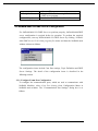
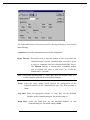
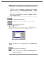
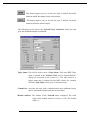
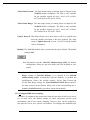
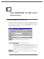
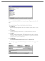
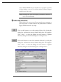
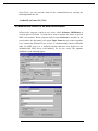
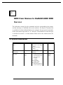
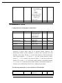
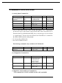
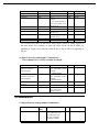
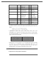
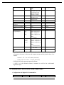
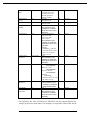
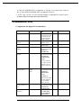
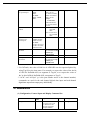
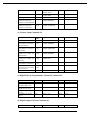
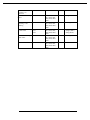
NuDAM-6000 DDE Server ver.6.1
User Guide
1
CONTENTS
CONTENTS ..........................................................................................................................................................2
I N T R O D U C T I O N T O N U D A M -6 0 0 0 D D E S E R V E R ....................................................................3
1.1 WHAT IS DDE?........................................................................................................................................ 3
1.2 DDE CONVERSATION ........................................................................................................................... 4
G E T T I N G S T A R T E D.......................................................................................................................................6
2.1 NUDAM-6000 I/O DDE SERVER INSTALLATION.................................................................... 6
2.1.1 Installation............................................................................................................................................6
2.2 NUDAM-6000 I/O DDE SERVER CONFIGURATION ............................................................... 8
2.2.1 /Configure/Comm Port Configuration..............................................................................................8
2.2.2 /Configure/Topic Definition.............................................................................................................10
2.2.3 /Configure/DDE Server Settings......................................................................................................12
U S I N G N U D A M-6 0 0 0 I / O D D E S E R V E R W I T H I N T O U C H ..................................................14
3.1 DDE ITEM NAMES DEFINITION IN INTOUCH ............................................................................ 14
3.2 MONITOR THE COMMUNICATION STATUS OF MODULES ...................................................... 19
3.3 MONITOR THE STATUS OF AN DDE CONVERSATION ............................................................ 20
D D E I T E M N A M E S I N N U D A M -6 0 0 0 D D E S E R V E R ...............................................................22
4.1 SPECIAL COMMAND SET ................................................................................................................... 22
4.2 NUDAM-6017, 6018 ....................................................................................................................... 23
4.3 NUDAM-6011, 6012, 6013, 6014D ...................................................................................... 24
4.4 NUDAM-6021 ...................................................................................................................................... 25
4.4 NUDAM-6024 ...................................................................................................................................... 26
4.5 NUDAM-6050, 6052, 6053, 6054, 6060, 6063............................................................ 27
4.6 NUDAM-6056, 6058 ....................................................................................................................... 29
4.7 NUDAM-6080 ...................................................................................................................................... 30
4.7 TABLE FOR ALL ITEMS ....................................................................................................................... 32
A P P E N D I X I N T O U C H S A M P L E P R O G R A M ................................................................................37
2
1
Introduction to NuDAM -6 0 0 0 D D E
Server
NuDAM-6000 I/O DDE Server is an application for the Microsoft Windows 95
and Windows NT operating systems. It acts as a DDE (Dynamic Data Exchange)
Server and allows other Windows application programs to access data from
NuDAM-6000 series Modules. NuDAM-6000 I/O DDE Server communicates
with the NuDAM-6000 series Modules via serial lines. It may be used with
Wonderware InTouch and any Microsoft Windows program that is capable of
acting as a DDE Client.
1.1 What is DDE?
DDE (Dynamic Data Exchange) is a communication protocol designed by
Microsoft to allow concurrently running programs in the Windows environment
to exchange data and instructions with each other. It implements a client-server
relationship between the applications. The server application provides the data
and accepts requests from any other application interested in the data. The
requesting applications are called clients which can both read and write data
maintained by the server. Some applications such as InTouch and Microsoft
Excel can simultaneously be both a client and a server.
Client applications can use DDE for one-time data transfers or for continuous
data exchanges in which updates are sent as soon as new information is
available. For one-time data transfers, the client application only requests the
“snapshot” data from the server application. For example, as a macro for report
generation is executed in Excel, a link to another DDE program will be set up to
request the specified data. The link will be terminated after the requested data is
received. Then the received data are used to generate reports.
3
The continuous data exchanges mode is also named “hot link”. While a client
application sets up a link to another DDE program, it requests the server
application to advise the client whenever a specific item's value changes. These
data links will remain active until either the client or server program terminates
the link or the conversation. It is a very efficient means of exchanging data
because once the link has been established no communication occurs until the
specified data value changes. InTouch uses DDE to communicate with I/O
device drivers and other DDE application programs.
For InTouch, if the tagname are defined as I/O type, they can read or write their
values to or from another DDE compliant Windows program. For example,
InTouch can read or write their values to Excel, and Excel can also read or write
data to InTouch Database. Whenever the data from source are updated, the
remote data are updated automatically as soon as new information is available.
DDE can be used to dispatch control instructions to process-connected
instruments. With this ability, two or more related applications can be combined
together to make up a large size of super application. For example, Excel
spreadsheet can perform the optimal calculation for production. Thus, Excel
may read data from InTouch database, which are accessed from I/O controllers
or sensors. Reference to the data, the Excel spreadsheet performs some
complicated calculation. InTouch reads the calculated result back from Excel
and then uses this optimal value to control various production parameters.
1.2 DDE Conversation
Two Windows application wishing to exchange data must establish a
conversation. The client opens a channel to the server application by specifying:
l Server Application Name
For NuDAM-6000 DDE Server, the application name is NuDAM.
l Topic (Logical Device) Name
The DDE topic is a general classification of data within which multiple data
items may be "discussed" (exchanged) during the conversation. For
NuDAM-6000 DDE Server, the topic might be a NuDAM module name, e.g.
NM6011. The topic is active whenever at least one conversation has been
established between the server’s logical device and the outside world’s
applications (client). The topic is de-active when the last conversation to a
topic has terminated.
4
l
Items/Tagnames
Items are individual pieces of data that are passed between applications. An
item is active whenever any DDE conversation is referencing this item. All
the valid item names for NuDAM-6000 DDE server are mentioned in
chapter 4 of this manual. For example, the item name is “ADI” for client
application (e.g. InTouch) to get the digital input data of NuDAM6011.Please refer to the related chapter for the details.
The following statement is the DDE address convention for representing an
DDE conversation:
Application|Topic!Item
For example, to get the digital input data of NuDAM-6011 through NuDAM6000 DDE Server, the conversation might be the following (assume the topic
name is defined as NM6011):
NuDAM|NM6011!ADI
5
2
Getting Started
2.1 NuDAM-6000 I/O DDE Server Installation
2.1.1 Installation
The NuDAM-6000 DDE Server Setup program provided by ADLink’s Manual
& Software Utility CD performs all tasks necessary for complete installation.
step 1. Insert the ADLink’s “Manual & Software Utility” CD into your CDROM drive.
step 2. Click the Start button on the Taskbar, then choose Run.
step 3. Type x :\setup (x identifies the drive that contains the compact disc)
in Open text box, then click OK.
step 4. Setup first displays the main screen. Select Software Package.
step 5. Setup then displays the ADLink’s software products screen. Select
InTouch & DDE Server.
Setup then prompts the following screen. Select NuDAM 6000 DDE.
6
NuDAM-6000 DDE Setup first displays a Welcome dialog box. Please click
to go on installation.
Setup then prompts a user information dialog box including Name, Company
and Serial Number text fields. The “Serial Number” field must be filled in
correctly, otherwise the NuDAM-6000 DDE Server will run in DEMO version.
Setup then prompts a dialog box for you to specify the destination directory for
NuDAM-6000 DDE Server. The default path is C:\ADLink\NuDDE6. If you
want to install NuDAM-6000 DDE Server in another directory, please click
Browse button to change the destination directory.
Then you click Next button to go on the installation.
While the installation is completed, the Install directory should contain the
following files:
File/Sub-directory
Samples <DIR>
Samples\NuDAM.cfg
NuDAM.exe
NuDAM32.exe
NuDAM.hlp
NuDAM.cnt
Description
InTouch Sample programs
Configuration file for running sample
programs
NuDAM 6000 series 32-bit DDE Server
Program
NuDAM 6000 series Administrating Utility
NuDAM 6000 series 32-bit DDE Server Help
File
NuDAM 6000 series 32-bit DDE Server Help
7
Wwdlg32.dll
NuDDE6.pdf
Contents File
Required DLL file for running NuDAM-6000
DDE server program
NuDAM-6000 DDE Server User’s Manual
2.2 NuDAM-6000 I/O DDE Server Configuration
For NuDAM-6000 I/O DDE Server to perform properly, NuDAM-6000 DDE
server configuration is required before its operation. To perform the required
configurations, start up NuDAM-6000 I/O DDE Server by clicking NuDAM6000 DDE Server V6.01 from program files menu and then the NuDAM main
window is shown as follows:
The configuration items include Com Port settings, Topic Definition and DDE
Server Settings. The detail of the configuration items is described in the
following sections.
2.2.1 /Configure/Comm Port Configuration
To configure the communication ports, which are used to communicate with
NuDAM Modules, select Com Port Setting from Configuration Menu in
NuDAM main window. The "Communication Port Settings" dialog box is as
follows:
8
The fields and buttons in Communication Port Settings dialog box are described
in the following:
Comm Port: Select the communication port for this configuration
Reply Timeout: This field is used to input the amount of time (in seconds) the
NuDAM modules on this communication port will be given
to reply to commands from the NuDAM-6000 DDE Server.
The Timeout message is sent out when a NuDAM module
fails to respond. The value is valid from 1 to 32 and the
default value is 3 seconds.
Note: Except that the Baud Rate is lower than 2400, the default value of 3
seconds should be sufficient for most NuDAM modules.
Parity: Select the Parity setting which matches the configuration of the
NuDAM modules on this communication port. The default setting is
None.
Stop Bits: Select the appropriate number of "Stop Bits" for the NuDAM
Modules on this communication port. The default setting is 1.
Baud Rate: Select the Baud Rate for the NuDAM Modules on this
communication port. The default setting is 9600.
9
Note:
1. The settings for all the modules on the same communication port have to be
the same.
2. If you wish to change the Baud Rate or Checksum settings of NuDAM
Modules, it is required to use NuDAM Administrating utility, accompanied
with the modules, to perform the modifications. Hence, the settings for
NuDAM-6000 I/O DDE Server must be the same as those on the modules.
Please refer to the corresponding user’s manuals of NuDAM modules you
wish to operate for the details.
Push this button to close the dialog box.
Push this button to save the settings after the configuration is finished.
Set all the settings as the default values.
2.2.2 /Configure/Topic Definition
To define the Topics, select Topic Definition from Configuration Menu in
NuDAM main window. The "Topic Definition" dialog box is as follows:
The fields and buttons in Topic Definition dialog box are described in the
following:
Push this button to close the dialog box.
Define a new topic and the NuDAM Topic Definition dialog box
displays as the figure below.
10
This button appears only as at least one topic is defined. Push this
button to modify the settings for the selected topic.
This button appears only as at least one topic is defined. Push this
button to delete the selected topics.
The following section shows the NuDAM Topic Definition dialog box and
gives the detailed description of each field:
Topic Name: This field is used to enter a Topic Name . (The same DDE Topic
Name is entered in the InTouch "DDE Access Name definition"
dialog box described in the section 3.1). The topic must be a
unique name that is matched by the DDE clients (for example
InTouch). Topic Name can be up to 32 characters long.
Comm Port: Associate the topic with a communication port (additional topics
may be associated with this same port at a later time).
Module Address: The address of the NuDAM mode configured. The valid
range of the module Address is from 0 to 255. The default
value is 1.
11
AI/AO Data Format: The data format setting of Analog Input or Output for the
NuDAM module configured. The field is only available
for the modules support AI (6011, 6012, 6013, 6014D,
6017 and 6018) or AO (6021, 6024).
AI/AO Data Range: The data range setting of Analog Input or Output for the
NuDAM module configured. The field is only available
for the modules support AI (6011, 6012, 6013, 6014D,
6017 and 6018) or AO (6021, 6024).
Update Interval: This field tells the server how often it will try to poll the data
from the module associated to the topic defined. The valid
range of Update Interval is from 1 to 65535 and the default
value is 1000(msec).
Module: The NuDAM module name associated to the topic defined. The default
setting is 6011.
Push this button to invoke NuDAM Administrating utility for module
configuration. Please be sure this utility has been installed in your
system.
Note: If you wish to change the address, AI/AO Data Format or AI/AO Data
Range settings of NuDAM Modules, it is required to use NuDAM
Administrating utility, accompanied with the modules, to perform the
modifications. Hence, the module address, AI/AO Data Format and
AI/AO Data Range settings for NuDAM-6000 I/O DDE Server must be
the same as those on the module. Please refer to the corresponding user’s
manual of NuDAM modules you wish to operate for the details.
2.2.3 /Configure/DDE Server Settings
A number of parameters that controls the internal operation of the Server can be
set. In most cases, the default settings for these parameters provide good
performance and do not require changing. However, they can be changed to
fine-tune the Server for a specific environment. To configure the NuDAM-6000
12
DDE Server, select DDE Server Settings from Configuration Menu in NuDAM
main window. The "DDE Server Settings " dialog box is as follows:
The fields and buttons in dialog box above are described in the following:
Configuration File Directory: This field is used to specify the path (disk drive
and directory) in which the NuDAM-6000 DDE
server will save its configuration file. NuDAM6000 DDE server will use this path to load the
configuration file the next time it is started. The
default path is the path that the NuDAM-6000
DDE Server program located.
Note: Only the "path" may be modified with this field. The configuration file is
always named NuDAM.cfg.
Protocol Timer Tick: This field is used to change the frequency, where the
Server executes the communication protocol. The valid
range of the Protocol Timer Tick is from 1 to 65535
and the default value is 50 msec.
NetDDE being used: This field must be checked when Wonderware NetDDE
is used.
Push this button to close "DDE Server Settings" dialog box and
cancel this command.
Push this button to save the settings and close "DDE Server Settings"
dialog box after the configuration is finished.
13
3
Using NuDAM-6000 I/O DDE Server
with InTo uch
3.1 DDE Item Names Definition in InTouch
For InTouch, the DDE item name can be defined in Tag Name Dictionary to
read/write data from other applications. To define the tagnames, invoke the
/Special/Tag Name Dictionary... command (in WindowMaker). The " Tagname
Dictionary " dialog box will appear:
Click on this button to define a new Tag Name
Enter the Tagname in this field. (The tagname defined here is the
name InTouch will use. The NuDAM-6000 DDE Server does not
see this name. The item name that NuDAM-6000 DDE Server uses
is defined in Item Name field, an input field in Details box).
Click on this button to select the tag type. The Tag Types dialog box
is as follows:
14
To access NuDAM-6000 DDE Server items, the type of Tagname should be I/O
type.
There are four I/O types. They are briefly described in the following:
l I/O Discrete
Discrete input/output tagname with a value of either 0 (False, Off) or 1 (True,
On).
l I/O Integer
A 32-bit signed integer value between -2,147,483,648 and 2,147,483,647.
l I/O Real
Floating (decimal) point tagname. The floating point value may be between
-3.4e38 and +3.4e38 . All floating point calculations are performed with 64-bit
resolution, but the result is stored in 32-bit.
l I/O Message
Text string input/output tagname that can be up to 131 characters long.
After selecting tag types, the "Details" dialog box associated to the tag type will
appear:
15
Note: If Details dialog box does not appear, click Details at the top of the
Tagname Dictionary dialog box.
Input all the information related to the tag name. If selecting I/O Integer or I/O
Real as the type for your tagname, it is required to input the values of Min EU,
Max EU, Min Raw and Max Raw.
Click on this button to define the DDE access name
associated to the tagname. The Access Name dialog
box is as follows:
Click on this button to close the dialog box.
Click on this button to define a new DDE access name.
Click on this button to modified the selected DDE access name. An
Modify Access Name dialog box will appear.
Click on this button to delete the selected DDE access name.
The following figure illustrate the Add/Modify Access Name dialog box:
16
Enter an arbitrary name. InTouch uses Access Names to
reference real-time I/O data of tagname associated to the
Access name. (It is generally advisable that the same name
defined for the NuDAM-6000 DDE topic is used here.)
If the data resides in a network I/O Server, type the remote node's
name in the field.
In this field, type the actual program name, NuDAM, for the
NuDAM-6000 DDE Server program from which the data
value will be acquired.
Note: Do not enter the .exe extension portion of the
program name.
In this field, type the topic name you want to access. The "Topic
Name " MUST be the same name used when the topics were
configured in the NuDAM-6000 I/O DDE Server program.
17
Select Advise all items if you want the server program to poll for
all data whether or not it is in visible windows, alarmed, logged,
trended or used in a script.
Note: Selecting this option will impact performance, therefore its
use is not recommended.
Select Advise only active items if you want the server program to
poll only points in visible windows and points that are alarmed,
logged, trended or used in any script.
Click on this button to save the settings followed by closing the
dialog box and then the Access Names dialog box will reappear.
Click “Done” to close the dialog box and return to Tagname
Dictionary dialog box and Details dialog box as the figure below.
Click on this button to cancel the command followed by closing the
dialog box and then the Access Names dialog box will reappear.
Click “Done” to close the dialog box and return to Tagname
Dictionary dialog box and Details dialog box as the figure below.
18
The last step is to define the DDE item name. In this field, type the item name
for the desired data value in the NuDAM-6000 DDE Server. Please refer to the
chapter 4 for the valid item names of each NuDAM module. For example, to
access the module name of NuDAM6011 module, type AM in this field.
Note: It is important to understand that the "tagname" is the name used within
InTouch to refer to a data value. The Item is the name used by I/O DDE
Server program to refer to the same value. These names do not have to
be the same, however, it is recommended when applicable to use the
same names.
3.2 Monitor the Communication Status of Modules
For each module being used, there is a built- in discrete item, Status , that you
can use to monitor the state of the communications with NuDAM module.
Status is set to "0" when communications with the device fails and set to "1"
when communications is successful. From InTouch, you can read the state of the
communications by defining a tagname and associating it with the topic
configured for the device by using the word Status as the item name. The
following figure is an example of Tagname Definition for monitoring the status
of all communication to a NuDAM module in InTouch.
19
From Excel, you can read the status of the communications by entering the
following formula in a cell:
=NuDAM|TopicName!'STATUS'
3.3 Monitor the Status of an DDE Conversation
InTouch also supports a built- in topic name called IOStatus (DDEStatus in
versions prior to InTouch 7.0) that can be used to monitor the status of specific
DDE conversations. When using the built- in topic IOStatus to monitor an I/O
conversation, the item name is the actual Topic Name that you want to monitor.
Let's assume that WindowViewer (View) is communicating with the NuDAM6000 I/O DDE Server to a NuDAM module that has been defined in the
NuDAM-6000 DDE Server with Module1 for its topic name. The tagname
definition is as the following figures:
20
Excel can also be used to perform this same type of monitoring by entering the
same information in a formula in a spreadsheet cell. For example, to monitor the
same topic as above, the following would be entered:
=View|IOStatus!'Module1'
21
4
DDE Item Names In NuDAM-6000 DDE
Server
The following sections list the commands and the corresponding item names
and the data types of NuDAM 6000 series modules. The Special Command Set
is available for all the NuDAM 6000 series modules. Except special commands,
all the item names begin with an “A” character. The definition of each data type
is described in section 3.1 of this manual. Please refer to the related section for
the details.
4.1 Special Command Set
Command
Read host watchdog
status
Item Name
WL
Read Command Leading
Code Setting
Read Host WatchDog /
Safe Value
WLC
WD
WD1
WD2
Requested / Poked value
bit0: reserved
bit1: Power or watchdog
failure
bit2: Host watchdog
failure
bit3: Host failure
Example:$#%@~*
(default)
WD (Flag):
Enable/Disable host
watchdog timer and
safe state value.
0: disable
1: enable
WD1 (TimeOut):
xx (01H– FFH)
WD2 (SafeValue):
The format depends
on the module types
22
R/W
R
Data Type
Integer
R
Message
R
Integer
Integer
String
Set Host WatchDog / Safe WDC
Value
Host is OK
WH
Flag: Enable/Disable
W
host watchdog
timer and safe state
value.
0: disable
1: enable
TimeOut: xx(01H– FFH)
SafeValue: The format
depends on the
module types
Example: 1121C
1
Message
W
Discrete
R/W
R
Data Type
Message
R
Message
R
Message
R
Real
R,W
W
W
Integer
Discrete
Discrete
4.2 NUDAM-6017, 6018
Configuration and Analog Input Command Set
Command
Configuration Status
Item Name
A2
Read Firmware Version
AF
Read Module Name
AM
Read Analog Input from AI0.... AI7
Channel N
Channel Status
A5
Span Calibration
A0
Offset Calibration
A1
Requested / Poked value
TTCCFF
TT:input range code
CC:baud rate code
FF:8-bit parameter
example: 090600
Version
example: A2.10
Module Name
example: 6017
Data: +-xxxxx.
example: 1.4567
0 to 255
1
1
* For NuDAM-6000 DDE server, using A5 to read or set channel status, the
requested or poked values must be in decimal format. However, the
hexadecimal format of the requested or poked value represents the real
meaning of the value. The bit 3 ~ 0 of the first character of the hexadecimal
value control channel 7 ~ 4. The bit 3 ~ 0 of the second character control
channel 3 ~ 0. For example, the requested data is 72 and the hexadecimal
format of 72 is 0x48. ‘4’ is 0100 means enable channel 6 and disable channel
7, 5, 4. And ‘8’ is 1000 that means enable channel 3 and disable channel 2, 1,
0. Please refer to NuDAM-6017/6018 User’s Manual for the details.
The following commands are only available for NUDAM-6018
Command
CJC status
Item Name
A3
CJC Offset Calibration
A9
Requested / Poked value
Data: +-xxxxx
example: 36.8
Counts: +-0 ~ 65535
23
R/W
R
Data Type
Real
W
Integer
4.3 NUDAM-6011, 6012, 6013, 6014D
(1) Analog Input Command Set
Command
Read Analog Input /
Read Analog Input from
Channel 0
CJC Status
Item Name
Requested / Poked value
R/W
Data Type
AAI
AA1
A3
R
R
Real (AAI)
Integer (AA1)
Real
Read Synchronized Data
A4
R
Real
Span Calibration
Offset Calibration
CJC Offset Calibration
A0
A1
A9
ex: 1.6888 (for AAI)
ex: 12345 (for AA1)
data: +-xxxxx.
example: 36.8
data
example: 5.822
1
1
counts: +-0 - 65535
W
W
W
Discrete
Discrete
Integer
* AA1 is only valid for 6011, 6012, 6014D that support Two’s complements
hexadecimal type of data format. Since the data have been converted to be in
Decimal format by NuDAM-6000 DDE Server, the data type of received data
is “signed integer”. Please refer to the ND-6011/6012/6014D user’s manual for
the details of data format for Analog output.
* A3, A9 are only valid for 6011.
* A4 is NOT available for 6013.
The following command is only available for NUDAM-6013
Command
Item Name
Read Analog Input from AI0.... AI2
Channel N
Requested / Poked value
Data: +-xxxxx.
example: 1.4567
R/W
R
Data Type
Real
(2) Configuration Command Set
Command
Configuration Status
Item Name
A2
Read Firmware Version
AF
Read Module Name
AM
Requested / Poked value
TTCCFF
TT:input range code
CC:baud rate code
FF:8-bit parameter
example:090600
Version
example:A2.10
Module Name
example:6011
R/W
R
Data Type
Message
R
Message
R
Message
(3) Digital I/O, Alarm and Event Command Set
This command set is ONLY available for 6011, 6012 and 6014D
24
Command
Synchronized Sampling
Read Digital In
Digital Out
Item Name
AS
ADI
ADO
Alarm Status
Read Event Counter
High Alarm Value
AEA
ARE
AH
Low Alarm Value
AL
Clear Latch Alarm
Clear Event Counter
ACA
ACE
Requested / Poked value
1
0 or 1
0 to 3
example:
3=112, indicates both of
the status of DO 0 and
DO1 are on
0 to 2
data: 00000 – 65535
data: high alarm
example: 2.05
data: low alarm
example: -0.375
1
1
R/W
W
R
R,W
Data Type
Discrete
Integer
Integer
R,W
R
R,W
Integer
Integer
Real
R,W
Real
W
W
Discrete
Discrete
* For InTouch, the value of Nth bit of ADO can be poked by using Tag.0N as
the item name. For example, to poke the value of the 0th bit of ADO, set
tagname as Tag.00, or to poke the value of the 1st bit of ADO, set tagname as
Tag.01.
(4) Data Conversion and Display Command Set
This command set is ONLY available for 6014D
Command
Read/Write Source
High/Low Values for
Linear Mapping
Item Name
A3
Read/Write Target
High/Low Values for
Linear Mapping
A5
Enable/Disable Linear
Mapping
Select LED Data Origin
Send LED Data
AA
A8
A9
Requested / Poked value
Data format:
(low_value)(high_Value)
example:
+04.000+20.000
Data format:
(low_value)(high_Value)
example:
+000.00+200.00
0 or 1
R/W
R,W
Data Type
String
R,W
String
R,W
Dis crete
1 or 2
Data:+-xxxxx.
Max. value:19999
example: 1999.9
W
W
Integer
Real
4.4 NUDAM-6021
Configuration and Analog Output Command Set
Command
Configuration Status
Item
Name
A2
Requested / Poked value
R/W Data Type
TTCCFF
TT:input range code
CC:baud rate code
FF:8-bit parameter
example:090600
R
25
Message
Read Firmware Version
AF
R
Message
R
Message
R
R
Discrete
AAO1
AAO2
AAO3
Version
example: A2.10
Module Name
example: 6021
S: 0,1
Data
ex: 02.000 (for A6)
ex: 2047 (for A6H)
Data
ex: 18.773 (for A8)
ex: 2047
Format*:
ex: 12.345 (xx.xxx)
ex: 023.45 (xxx.xx)
ex: 4095 (xxxx)
Read Module Name
AM
Reset Status
Last Value Readback
A5
4 mA Calibration
20 mA Calibration
A0
A1
1
1
W
W
Real (AAO1)
Real (AAO2)
Integer (in decimal
format, AAO3)
Discrete
Discrete
Trim Calibration
A3
W
Integer
Save Power on AO
Value
A4
counts: 0 – 95 or
161 – 255*
1
W
Discrete
A6
A6H
Current Readback
A8
A8H
Analog Data Out
Real (A6)
Integer (A6H)
R
Real (A8)
Integer (A8H)
W
* For using A3 to perform Trim Calibration, the relationship between the number
of counts to increase or decrease the output current and the poked values is as
follows:
counts 0 – 95 : 0 to +95 counts (increase)
counts 161-255: -95 to –1 counts (decrease)
* NuDAM-6021 supports three types of data format. Please refer to the
NuDAM6021 user’s manual for the details of data format for Analog output.
For NUDAM-6000 DDE server, the relationship between item names and data
format is listed in the following table:
Data Format
Engineering Units
Percent of FSR
Hexadecimal Format
Item Name
AAO1
AAO2
AAO3
Though AAO3 is the item name for AO in Hexadecimal Format, the poked
data MUST been in DECIMAL format. NuDAM-6000 DDE Server will
convert the poked data to be Hexadecimal format before the data sent to
NuDAM module. The valid range of poked data is from 0 to 4095.
4.4 NUDAM-6024
Configuration and Analog Output Command Set
26
Command
Configuration Status
A2
Read Firmware Version
AF
Read Module Name
AM
Reset Status
Digital In
Digital In from
Channel N*
Synchronized Sampling
Read Synchronized Data
status
Read Synchronized Data
Last Value Readback for
the specified port
A5
ADI
ACI0…ACI6
Requested / Poked
value
TTCCFF
TT:input range code
CC:baud rate code
FF:8-bit parameter
example:090600
Version
example: A2.10
Module Name
example: 6024
S: 0,1
0 to 127
0 or 1
AS
A8S
Analog Data Out*
Item Name
R/W Data Type
R
Message
R
Message
R
Message
R
R
R
Discrete
Integer
Integer
1
0 or 1
W
R
Discrete
Discrete
A8
A6A
A6B
A6C
A6D
0 to 127
A6A: output port A
A6B: output port B
A6C: output port C
A6D: output port D
R
R
Integer
Real
AAOA,
AAOB,
AAOC,
AAOD
Data:
ex: 02.000
AAOA: output port A
AAOB: output port B
AAOC: output port C
AAOD: output port D
W
Real
W
Integer
W
Discrete
Trim Calibration
A3
Save Power on AO
Value
A4
Data:
ex: 12.345 (xx.xxx)
counts: 0 – 95 or
161 – 255*
1
* For using A3 to perform Trim Calibration, the relationship between the number
of counts to increase or decrease the output current and the poked values is as
follows:
counts 0 – 95 : 0 to +95 counts (increase)
counts 161-255: -95 to –1 counts (decrease)
* NuDAM-6024 only supports engineering format.
* “ACIn” (n is the channel number) command is used for the n-th channel
digital data input.
4.5 NUDAM-6050, 6052, 6053, 6054, 6060, 6063
Configuration and Digital I/O Command Set
Command
Item Name
Requested / Poked value
27
R/W
Data Type
Configuration
Status
A2
Read Firmware
AF
Version
Read Module Name AM
Synchronized
Sampling
AS
Digital Data In
ADI
Digital In from
Channel N*
ACI0…ACI15
Digital Data Out
ADO
Digital Data Out for ACO0…ACO7
Channel N*
Reset Status
A5
Read Synchronized A4
Data Status
TTCCFF
TT:input range code
CC:baud rate code
FF:8-bit parameter
example: 090600
Version
example: A2.30
Module Name
example: 6050
1
this command is only
available for NUDAM6050, 6052, 6053, 6054
and 6060
0 to 255: 6050, 6052
0 to 65535: 6053
0 to 32767: 6054
0 to 15: 6060
this command is only
available for NUDAM6050, 6052, 6053, 6054
and 6060
example:
3=000000112, indicates
the status of DO 0 and
DO 1 are on and the
others are off.
0 or 1
this command is only
available for NUDAM6050, 6052, 6053, 6054
and 6060
Data: 0 to 255 for
NUDAM-6050
Data: 0 to 15 for
NUDAM-6060
Data: 0 to 255 for
NUDAM-6063
example:
8=000010002,
R
Message
R
Message
R
Message
W
Discrete
R
Integer
R
Integer
R,W
Integer
indicates DO3 is on, and
the others are off.
0 or 1
R,W
this command is only
available for NUDAM6050, 6060 and 6063
S: 0, 1
R
0 or 1
R
this command is only
available for NUDAM6050, 6052, 6053, 6054
and 6060
Integer
Discrete
Discrete
* For InTouch, the value of Nth bit of ADI/ADO can be requested/poked by
using Tag.0N as the item name. For example, to request the value of the 0th bit
28
of ADI for NuDAM-6050, set tagname as Tag.00, or to request the value of
the 3th bit of ADI for NuDAM-6050, set tagname as Tag.03.
* “ACIn” and “ACOn” (n is the channel number) commands are used for the nth channel digital data input and output individually.
4.6 NUDAM-6056, 6058
Configuration and Digital I/O Command Set
Command
Item Name
Configuration Status
A2
Read Firmware
Version
Read Module Name
AF
Synchronized
Sampling
AS
Digital Data In for DI
channels
ADI
AM
Digital Data In for a ADIA,
specified port
ADIB,
ADIC
Digital Data In for all
the DI channels and
ports
ADIT
Digital In from
Channel N
ACI0…ACI27*
Requested / Poked
value
TTCCFF
TT:input range code
CC:baud rate code
FF:8-bit parameter
example: 090600
Version
example: A2.30
Module Name
example: 6050
1
this command is only
available for
NUDAM-6058
0 to 15: 6058
this command is only
available for
NUDAM-6058
example:
3=00112, indicates
R/W
Data Type
R
Message
R
Message
R
Message
W
Discrete
R
Integer
the status of DO 0
and DO 1 are on
and the others are
off.
0 to 255
R
this command is only
available for
NUDAM-6058
example:
3=000000112,
indicates the status
of DO 0 and DO 1
are on and the
others are off.
0 to 268435455
R
this command is only
available for
NUDAM-6058
0 or 1
R
this command is
only available for
NUDAM-6058
29
Integer
Integer
Integer
Digital Data Out for
the specified port
For 6056:
ADOH,
ADOL
For 6058:
ADOA, ADOB,
ADOC
For ADOH:
Data: 0 to 127
For ADOA, ADOB,
ADOC and ADOL:
Data: 0 to 255
example:
8=000010002,
Digital Data Out for
all Ports
ADOT
Digital Data Out for
channel N of a
specified port
For 6056:
ACOH0…ACOH7
ACOL0…ACOL7
For 6058:
ACOA0…ACOA7
ACOB0…ACOB7
ACOC0…ACOC7
APIO
Set Programmable
I/O Mode
Reset Status
Read Synchronized
Data Status
A5
A4
R,W
Integer
R,W
Integer
R,W
Integer
Data: 0 to 15
R,W
this command is only
available for
NUDAM-6058
S: 0, 1
R
0 or 1
R
this command is only
available for
NUDAM-6058
Integer
indicates DO3 is
on, and the others
are off.
Data: 0 to 32767 for
NUDAM
6056
Data: 0 to 16777215
for NUDAM
6058
Data: 0 or 1
Discrete
Discrete
* For InTouch, the value of Nth bit of ADI/ADO can be requested/poked by
using Tag.0N as the item name. For example, to request the value of the 0th bit
of ADI for NuDAM-6050, set tagname as Tag.00, or to request the value of
the 3th bit of ADI for NuDAM-6050, set tagname as Tag.03.
* “ACIn” and “ACOpn” (p is the port number and n is the channel number)
commands are used for the n-th channel digital data input and n-th channel
digital data output from output port p individually.
4.7 NUDAM-6080
(1) Configuration, Counter Input and Display Command Set
Command
Configuration Status
Item
Name
A2
Requested / Poked value R/W
Data Type
TTCCFF
TT:input range code
CC:baud rate code
FF:8-bit parameter
example: 090600
Message
30
R
Read Firmware Version
Read Module Name
Input Signal Mode
Read Counter/ Frequency
Value of counter 0 or
Counter 1 in Hexadecimal
Read Counter/ Frequency
Value of counter 0 or
Counter 1 in Decimal
AF
Version
example: B2.10
AM
Module Name
example: 6080
AB
S: 0, 1
A0 or A1 Data: xxxxxxxx
example: 00002FFF
R
Message
R
Message
R, W
R
Discrete
Message
A0D or
A1D
R
Real
Data: xxxxxxxxxx
example: 1234567890
(2) Counter Setup Command Set
Command
Gate Mode
Maximum Counter Value
of counter 0 or Counter 1
in Hexadecimal
Maximum Counter Value
of counter 0 or Counter 1
in Decimal
Initial Counter value of
counter 0 or Counter 1 in
Hexadecimal
Initial Counter value of
counter 0 or Counter 1 in
Decimal
Counter Start/Stop Status
of counter 0 or Counter 1
Read then Clear the
Overflow Flag of counter
0 or Counter 1
Clear Counter
Item
Name
AA
A30 or
A31
Requested / Poked value R/W
Data Type
G: 0, 1, 2
Data: xxxxxxxx
example: 0000FFFF
R, W
R, W
Integer
Message
A0C or
A1C
Data: xxxxxxxxxx
Example: 4294967295
R, W
Real
AG0 or
AG1
Data: xxxxxxxx
Example: 000000FF
R, W
Message
A0E or
A1E
Data: xxxxxxxxxx
Example: 255
R, W
Real
A50 or
A51
A70 or
A71
S: 0, 1
R, W
Discrete
V: 0, 1
R
Discrete
A6
N: 0, 1
W
Discrete
(3) Digital Filter & Programmable Threshold Command Set
Command
Digital Filter Status
Minimum Input Signal
Width at High Level
Minimum Input Signal
Width at Low Level
TTL Input High Trigger
Level
TTL Input Low Trigger
Level
Item Name Requested / Poked value R/W
A4
S: 0, 1
R, W
A0H
Data: 4 – 1024
R, W
Data Type
Discrete
Integer
A0L
Data: 4 – 1024
R, W
Integer
A1H
Data: 1 – 50
R, W
Integer
A1L
Data: 1 – 50
R, W
Integer
(4) Digital Output & Alarm Command Set
Command
Item Name Requested / Poked value R/W
31
Data Type
Enable/Disable Alarm
Status of Counter0 or
Counter1
Read Alarm Status
AE0 or
AE1
Alarm Limit Value of
Counter 0 in
Hexadecimal
Alarm Limit Value of
Counter 0 in Decimal
Alarm Limit Value of
Counter 1 in
Hexadecimal
Alarm Limit Value of
Counter 1 in Decimal
Digital Output Value
APA
AEA
APD
ASA
ASD
ADO
S: 0, 1
where 0: disable alarm
1: enable alarm
S: 0 – 3
Example: 3 = 112 ,
indicates that the alarm
status of counter 0 and
counter 1 are enabled.
Data: xxxxxxxx
Example: F0000000
W
Discrete
R
Integer
R, W
Message
Data: xxxxxxxxxx
Example: 4026531840
Data: xxxxxxxx
Example: F0000000
R, W
Real
R, W
Message
Data: xxxxxxxxxx
Example: 4026531840
Data: 0 – 3
Example: 3 = 112 ,
indicates that the
status of DO0 and
DO1 are on.
R, W
Real
R, W
Integer
4.8 Table for All Items
All the Item names used by NuDAM-6000 I/O DDE Server are listed in the
following table:
Command
Span Calibration
4 mA Calibration
Item Name
A0
Read
Counter/ A0
Frequency
Value of Counter 0 in
Hexadecimal
Read
Counter/ A1
Frequency
Value of Counter 1 in
Hexadecimal
Offset Calibration
A1
20 mA Calibration
Configuration
Status
A2
CJC Status
Trim Calibration
A3
A3
Module Name
6011, 6012, 6013,
6014D, 6017, 6018,
6021
6080
R/W
W
Data Type
Discrete
R
Message
6080
R
Message
6011, 6012, 6013,
6014D, 6017, 6018,
6021
6011, 6012, 6013,
6014D, 6017, 6018,
6021, 6024, 6050,
6052, 6053, 6054,
6056, 6058, 6060,
6063, 6080
6011, 6018
6021, 6024
W
Discrete
R
Message
R
W
Real
Integer
32
Read/Write Source
High/Low Values for
Linear Mapping
Read Synchronized
Data
Save Power on AO
Value
Read Synchronized
Data Status
A3
6014D
R,W
A4
6011, 6012, 6014D
R
Real
A4
6021, 6024
W
Discrete
A4
R
Discrete
Digital Filter Status
Read,Enable/Disable
Channels for
Multiplexing
Reset Status
A4
A5
6024, 6050, 6052,
6053, 6054, 6058,
6060
6080
6013, 6017, 6018
R, W
R, W
Discrete
Integer
R
Discrete
Read/Write Target
High/Low Values for
Linear Mapping
Last Va lue Readback
A5
Last Value Readback
Clear Counter
Current Readback
Select LED Data
Origin
Read Synchronized
Data
Read Synchronized
Data
status
Send LED Data
CJC Offset
Calibration
Maximum Counter
Value of counter 0
in Hexadecimal
Maximum Counter
Value of Counter 1
in Hexadecimal
Counter Start/Stop
Status of Counter 0
Counter Start/Stop
Status of Counter 1
Read then Clear the
overflow flag of
counter 0
Read then Clear the
overflow flag of
counter 1
Maximum Counter
Value of counter 0
in Decimal
A5
String
6021, 6024, 6050,
6052, 6053, 6054,
6056, 6058, 6060,
6063
6014D
R,W
A6
A6H
A6A…
A6D
A6
A8
A8H
A8
6021
R
6024
R
6080
6021
W
R
6014D
W
Discrete
Real (A8)
Integer (A8H)
Discrete
A8
6024
R
Integer
A8S
6024
R
Discrete
A9
A9
6014D
6011, 6018
W
W
Real
Integer
A30
6080
R, W
Message
A31
6080
R, W
Message
A50
6080
R, W
Discrete
A51
6080
R, W
Discrete
A70
6080
R
Discrete
A71
6080
R
Discrete
A0C
6080
R, W
Real
33
String
Real (A6)
Integer (A6H)
Real
Maximum Counter
Value of counter 1
in Decimal
Read Counter/
Frequency Value of
counter 0 in
Decimal
Read Counter/
Frequency Value of
counter 1 in
Decimal
Initial Counter value
of counter 0 in
Decimal
Initial Counter value
of Counter 1 in
Decimal
Minimum Input
Signal Width at
Low Level
Minimum Input
Signal Width at
High Level
TTL Input Low
Trigger Level
TTL Input High
Trigger Level
Gate Mode
Enable/Disable
Linear
Mapping
Read Analog Input /
Read Analog Input
from channel 0
Analog Data Out
Analog Data Out
Input Signal Mode
Clear Latch Alarm
Clear Event Counter
Digital Input from
Channel N
Digital Output for
Channel N
Digital Data Out for
channel N of a
specified port
Digital Data Out for
channel N of a
specified port
Digital Input
Digital Input
Digital Input from a
specified port
A1C
6080
R, W
Real
A0D
6080
R
Real
A1D
6080
R
Real
A0E
6080
R, W
Real
A1E
6080
R, W
Real
A0L
6080
R, W
Integer
A0H
6080
R, W
Integer
A1L
6080
R, W
Integer
A1H
6080
R, W
Integer
AA
AA
6080
6014D
R, W
R,W
Integer
Discrete
AAI
AA1
6011, 6012, 6013
R
Real (AAI)
Integer (AA1)
AAO1
AAO2
AAO3
AAOA… AAOD
AB
ACA
ACE
ACI0 … ACI27
6021
W
6024
6080
6011, 6012, 6014D
6011, 6012, 6014D
6011, 6012, 6014D,
6024, 6050, 6052,
6053, 6054, 6058,
6060,
6050, 6060, 6063
W
R, W
W
W
R
Real (AAO1)
Real (AAO2)
Integer (AAO3)
Real
Discrete
Discrete
Discrete
Integer
R, W
Integer
ACOH0…ACOH7
ACOL0…ACOL7
6056
R,W
Integer
ACOA0…ACOA7
ACOB0…ACOB7
ACOC0…ACOC7
ADI
ADI
6058
R,W
Integer
6011, 6012, 6014D
6024, 6050, 6052,
6053, 6054, 6058,
6060
6058
R
R
Discrete
Integer
R
Integer
ACO0 …ACO7
ADIA …
ADIC
34
Digital Input from all
the DI channels and
ports
Digital Output
ADIT
6056, 6058
R
Integer
ADO
R, W
Integer
Digital Output for a
specified port
Digital Output for a
specified port
ADOH,
ADOL
ADOA,
ADOB,
ADOC
ADOT
6011, 6012, 6014D,
6050, 6060, 6063,
6080
6056
R,W
Integer
6058
R,W
Integer
6056, 6058
R,W
Integer
AE0
6080
W
Discrete
AE1
6080
W
Discrete
AEA
6011, 6012
R,W
Integer
AEA
AF
R
R
Integer
Message
AG0
6080
6011, 6012, 6013,
6017, 6018, 6021,
6050, 6052, 6060,
6080
6080
R,W
Message
AG1
6080
R,W
Message
AH
6011, 6012
R,W
Real
AI0…AI7
6013, 6017, 6018
R
Real
AI0…AI2
6013
R
Real
AL
6011, 6012
R,W
Real
AM
R
Message
APA
6011, 6012, 6013,
6017, 6018, 6021,
6050, 6052, 6060,
6080
6080
R,W
Message
APD
6080
R,W
Real
APIO
6058
R,W
Integer
ARE
AS
6011, 6012
6011, 6012, 6050,
6060
6080
R
W
Integer
Discrete
R,W
Message
Digital Output for all
ports
Enable/Disable
Alarm Status of
Counter0
Enable/Disable
Alarm Status of
Counter1
Enable/Disable
Alarm
Read Alarm Status
Read Firmware
Version
Initial Counter value
of counter 0 in
Hexadecimal
Initial Counter value
of Counter 1 in
Hexadecimal
Read/Set High Alarm
Value
Read Analog Input
from Channel N
Read Analog Input
from Channel N
Read/Set Low Alarm
Value
Read Module Name
Alarm Limit Value of
Counter 0 in
Hexadecimal
Alarm Limit Value of
Counter 0 in
Decimal
Set Programmable
I/O Mode
Read Event Counter
Synchronized
Sampling
Alarm Limit Value of
Counter 1 in
Hexadecimal
ASA
35
Alarm Limit Value of
Counter 1 in
Decimal
Read host watchdog
status
ASD
6080
R,W
Real
WL
R
Integer
Read Command
Leading Code
Setting
WLC
6011, 6012, 6013,
6017, 6018, 6021,
6050, 6052, 6060,
6080
6011, 6012, 6013,
6017, 6018, 6021,
6050, 6052, 6060,
6080
6011, 6012, 6013,
6017, 6018, 6021,
6050, 6052, 6060,
6080
6011, 6012, 6013,
6017, 6018, 6021,
6050, 6052, 6060,
6080
6011, 6012, 6013,
6017, 6018, 6021,
6050, 6052, 6060,
6080
R
Message
R
Integer (WD)
Integer (WD1)
String (WD2)
W
Message
W
Discrete
Read Host WatchDog WD
/ Safe Value
WD1
WD2
Set Host WatchDog / WDC
Safe Value
Host is OK
WH
36
Appendix InTouch Sample Program
There are several InTouch sample programs provided in this software package. They
could help you to program your own applications by using InTouch and NuDAM6000 DDE Server easily. The brief descriptions of these sample programs are
specified as follows:
6011Demo
NuDAM-6011 InTouch Sample Program
6012Demo
NuDAM-6012 InTouch Sample Program
6013Demo
NuDAM-6013 InTouch Sample Program
6014Demo
NuDAM-6014D InTouch Sample Program
6017Demo
NuDAM-6017 InTouch Sample Program
6018Demo
NuDAM-6018 InTouch Sample Program
6021Demo
NuDAM-6021 InTouch Sample Program
6024Demo
NuDAM-6024 InTouch Sample Program
6050Demo
NuDAM-6050 InTouch Sample Program
6052Demo
NuDAM-6052 InTouch Sample Program
6053Demo
NuDAM-6053 InTouch Sample Program
6054Demo
NuDAM-6054 InTouch Sample Program
6056Demo
NuDAM-6056 InTouch Sample Program
6058Demo
NuDAM-6058 InTouch Sample Program
6060Demo
NuDAM-6060 InTouch Sample Program
6063Demo
NuDAM-6063 InTouch Sample Program
6080Demo
NuDAM-6080 InTouch Sample Program
NudamDemo1
NuDAM 6000 Series InTouch Sample Program
NudamDemo2
NuDAM-6017, 6050 InTouch Sample Program
To run these sample programs, please follow the following steps:
37
Step1. Execute NuDAM-6000 DDE Server program
Step 2. Configure NuDAM-6000 DDE Server properly
The topic names required for each sample program have to be defined. The
demo programs with their own corresponding topics are list in the following
table:
Demo Program
6011Demo
6012Demo
6013Demo
6014Demo
6017Demo
6018Demo
6021Demo
6024Demo
6050Demo
6052Demo
6053Demo
6054Demo
6056Demo
6058Demo
6060Demo
6063Demo
6080Demo
NudamDemo
NuDemo2
Topic Name
ND6011
ND6012
ND6013
ND6014D
ND6017
ND6018
ND6021
ND6024
ND6050
ND6052
ND6053
ND6054
ND6056
ND6058
ND6060
ND6063
ND6080
ND6011, ND6012,
ND6013, ND6017,
ND6018, ND6021,
ND6050, ND6052,
ND6060, ND6080
ND6011, ND6050
Please refer to chapter 2 for the detailed descriptions about the NuDAM-6000
DDE Server configuration.
A configuration file “NuDAM.cfg”, located in Samples directory, is provided.
This configuration file defines all the topic names required for executing our
sample programs. To use this configuration file, set the configuration file path
as the directory where this configuration file is located (the default is
“C:\ADLink\NuDDE6\Samples”), and then re-execute NuDAM-6000 DDE
Server program.
38
This configuration file will be used while NuDAM-6000 DDE Server program
is re-executed. For the configured topics fitting your system, use
“/Configure/Topic Definition” command to modify the contents of the topics
(e. COM port, module address, data format, … etc.). Please refer to section
2.2.2 for the detailed descriptions about topic definition.
Step 3. Start the InTouch program (INTOUCH.EXE) and select the InTouch sample
program you want to execute in the list in the InTouch Application Manager
dialog box. If the sample programs are not shown in the list, on the Tools
menu, click Find Applications. The Starting directory for search dialog box
appears and locates the directory in which you want to search for applications,
and then click OK. The InTouch Application Manager will reappear
displaying icons for all applications that were found in the selected directory.
Please refer to InTouch User’s Guide or related reference books to get the
information about using InTouch.
39