1
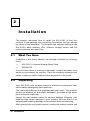
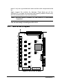
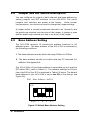
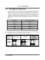
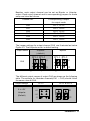
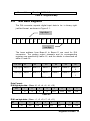
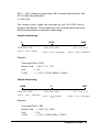
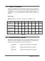
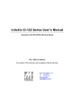
NuDAQ ACL-6126 6-Channel D/A Output & DIO Card User’s Guide @Copyright 1996~2000 ADLINK Technology Co., Ltd. All Rights Reserved. Manual Rev.3.35: June 1, 2000 The information in this document is subject to change without prior notice in order to improve reliability, design and function and does not represent a commitment on the part of the manufacturer. In no event will the manufacturer be liable for direct, indirect, special, incidental, or consequential damages arising out of the use or inability to use the product or documentation, even if advised of the possibility of such damages. This document contains proprietary information protected by copyright. All rights are reserved. No part of this manual may be reproduced by any mechanical, electronic, or other means in any form without prior written permission of the manufacturer. Trademarks NuDAQ is the registered trademark of ADLink Technology Inc. Other product names mentioned herein are used for identification purposes only and may be trademarks and/or registered trademarks of their respective companies. Getting service from ADLink ♦ Customer Satisfaction is always the most important thing for ADLink Tech Inc. If you need any help or service, please contact us and get it. ADLink Technology Inc. Web Site Sales & Service Technical Support TEL Address ♦ http://www.adlink.com.tw [email protected] NuDAQ [email protected] NuDAM [email protected] NuIPC [email protected] NuPRO [email protected] Software [email protected] AMB [email protected] +886-2-82265877 FAX +886-2-82265717 9F, No. 166, Jian Yi Road, Chungho City, Taipei, 235 Taiwan, R.O.C. Please inform or FAX us of your detailed information for a prompt, satisfactory and constant service. Detailed Company Information Company/Organization Contact Person E-mail Address Address Country TEL Web Site FAX Questions Product Model Environment to Use ¨OS: ¨Computer Brand : ¨M/B : ¨CPU : ¨Chipset : ¨Bios : ¨Video Card : ¨Network Interface Card : ¨Other : Challenge Description Suggestions for ADLink Contents Chapter 1 Introduction..................................................................1 1.1 1.2 1.3 1.4 Features.............................................................................. 2 Applications........................................................................ 2 Specifications..................................................................... 2 Software Support................................................................ 5 1.4.1 1.4.2 Programming Library.....................................................................5 LabView Driver................................................................................5 Chapter 2 Installation ....................................................................6 2.1 2.2 2.3 2.4 2.5 2.6 2.7 2.8 2.9 2.10 What You Have ................................................................... 6 Unpacking........................................................................... 6 ACL-6126's Layout............................................................... 7 Jumper and DIP Switch Description ................................... 8 Base Address Setting.......................................................... 8 IRQ Level Setting................................................................ 9 D/A Output Configuration.................................................. 10 Connector Pin Assignment................................................ 13 Signal Connection ............................................................ 15 Software Installation......................................................... 17 Chapter 3 Registers Format.......................................................18 3.1 3.2 3.3 3.4 I/O Port Address................................................................ 18 D/A Data Register.............................................................. 19 Digital I/O Register............................................................ 23 Demonstration Programs.................................................. 23 Product Warranty/Service ..........................................................25 Contents • i How to Use This Manual This manual is written to help you use the ACL-6126. The manual describes how to modify various settings on the ACL-6126 card to meet your requirements. It is divided into three chapters: Ø Chapter 1, "Introduction," gives an overview of the product features, applications and specifications. Ø Chapter 2, "Installation," describes how to install the ACL-6126, including the jumper setting for base address, interrupt IRQ level and D/A output ranges. The layout of ACL-6126 is also shown, Besides, all connectors' pins assignment are also specified. Ø Chapter 3, "Programming," describes how to program the ACL-6126 for analog outputs and digital I/Os. 1 Introduction The ACL-6126 provides 6-channel analog outputs, 16-channel digital inputs and 16-channel digital outputs add-on card for the IBM Personal Computer and compatible computers. It is designed for industrial control applications requiring analog outputs ( voltage and current )with 12-bit resolution in rugged environment. The ACL-6126 transmits six analog outputs with various user configurable ranges of : 0 ~ +10V, 0 ~ +5V ±10V, ±5V, and 4 to 20 mA current loop. Each D/A has a double-buffered output for single-step update and occupies its own I/O location. Also, a rugged and reliable 37-pin Dsub style connector is provided for analog outputs. In addition to the 6 analog outputs, the ACL-6126 has 16 digital inputs and 16 digital outputs, all of the digital channels are TTL compatible. The ACLD-9182 ( 16-bit Isolation digital input board) and ACLD-9185 ( 16-bit relay output board) are designed for connection with the digital input and output. We apply the state-of-the-art technology and components when designing ACL-6126. Its compact size PCB board let this card easily fit into any kind of chassis. Also, all the components on the card are SMT type,so it improves the reliability and quality of this card. Introduction • 1 1.1 Features Ø The ACL-6126 6-channel D/A Output Card provides the following advanced features: Ø AT Bus support Ø Six multiplying analog output channels Ø 12-bit resolution, double buffered D/A converter Ø Multiple Output Range : Unipolar : 0 ~ +5 V , 0 ~ +10 V Ø Bipolar : ± 5 V, ± 10 V Current Loop : 4 ~ 20mA All D/A outputs will be 0V after RESET or POWER-ON Ø 16 digital output channels Ø 16 digital input channels Ø Enhanced IRQ capability from IRQ3 to IRQ15 Ø 726 Register structure is fully compatible with Advantech's PCL- 1.2 Applications Ø Industrial and laboratory ON/OFF control Ø Energy management Ø Function generator Ø Programmable voltage source Ø Security controller Ø DIP loop control Ø Programmable current sink Ø Waveform and pulse generation 1.3 Specifications Ø Analog Output( D/A ) • Converter: DAC7541 AJP or equivalent • Conversion type : monolithic multiplying 2 • Introduction • Number of channels : 6 channels • Resolution : 12-bit, double buffered output Introduction • 3 • Output ranges : Unipolar :0V~+5V or 0~+10V Bipolar : ±5V or ± 10V 4 ~ 20mA current loop (sink) • Reference Voltage : ± 10V with external DC or AC reference; Internal : -5V or -10V • Current Loop : External : +10V or -10V max. • Settling time : 70 microsecond max. • Linearity : ± 1/2 bit • Accuracy : ± 0.012% of full scale range • Voltage driving capability : ± 5mA (max.) • Current Loop exciting voltage : 4 ~ 20 mA (sink) 8V(min.) , 36V(max.) for current loop 4mA ~ 20mA • Output initial status : 0V ( after RESET or POWER-ON) Ø • • • • • • Digital Input (D/I) Channel : 1 6 channels Level : TTL compatible Input logic low voltage : Min. -0.5V; Max. 0.8V Input logic high voltage : Min. 2.0V; Max. 5.0V Input loading current : Max. 0.2 mA at 0.4V Input hysteresis : Typical 0.4V; Min. 0.2V Ø Digital Output (D/O) • Channel : 1 6 channels • Level : TTL compatible • Input logic low voltage(Sink) : Max. 0.5V at 24mA Max. 0.4V at 12mA • Input logic high voltage (Source) : Min 2.0V at 15mA Min. 2.4V at 3mA • Driving Capacity : All inputs and outputs are TTL/DTL compatible and outputs will drive standard TTL load (74 series) or LSTTL (74LS) loads • Input hysteresis : Typical 0.4V; Min. 0.2V 4 • Introduction Ø General Specification • Bus: PC/AT bus • I/O connectors : 37-pin D-sub connector (analog output) 20-pin ribbon connector (digital I/O) • Operating temp: 0°C ~ 55°C • Storage temp : -20°C ~ 80°C • Humility : 5% ~ 95%, non-condensing • Power Consumption : +5V : 360mA typical 450mA max. +12V : 60mA typical 180mA max. -12V : 20mA typical 90mA max. • Dimension : Half-Size 163 mm x 123 mm 1.4 Software Support 1.4.1 Programming Library For the customers who are writing their own programs, we provide MS-DOS Borland C/C++ programming library. ACLS-DLL2 is the Development Kit for NuDAQ ISA-Bus Cards with Analog I/O, windows 3.1/95(98)/NT. ACLS-DLL2 can be used for many programming environments, such as VC++, VB, Delphi. ACLSDLL2 is included in the ADLINK CD. It need license. 1.4.2 LabView Driver The ACLS-LVIEW includes the ACL-6126’s Vis, which is used to interface with NI’s LabView software package. The ACLS-LVIEW supports Windows -95(98)/NT. ACLS-LVIEW is included in the ADLINK CD. It need license. Introduction • 5 2 Installation This chapter describes how to install the ACL-6126. At first, the contents in the package and unpacking information that you should be careful of are described. The jumpers and switches setting for the ACL-6126's base address, IRQ, refernce voltage source and DA output mode are also specified. 2.1 What You Have In addition to this User's Manual, the package includes the following items: Ø ACL-6126 6-channel Analog Output Card Ø ADLINK CD If any of these items is missing or damaged, contact the dealer from whom you purchased the product. Save the shipping materials and carton in case you want to ship or store the product in the future. 2.2 Unpacking Your ACL-6126 card contains sensitive electronic components that can be easily damaged by static electricity. The card should be put on a grounded anti-static mat. The operator should be wearing an anti -static wristband, grounded at the same point as the anti-static mat. Inspect the card module carton for obvious damage. Shipping and handling may cause damage to your module. Be sure there is no shipping and handling damage on the module before processing. After opening the card module carton, extract the system module and 6 • Installation place it only on a grounded anti-static surface with components side up. Again inspect the module for damage. Press down on all the socketed IC's to make sure that they are properly seated. Do this only with the module place on a firm flat surface. Note : DO NOT APPLY POWER TO THE CARD IF IT HAS BEEN DAMAGED. You are now ready to install your ACL-6126. SW1 JP6-3 JP6-2 JP5-2 JP4-3 JP4-2 JP3-1 JP2-1 JP1-1 JP3-2 JP3-3 CN2 JP1-2 JP2-2 JP7 JP2-3 JP1-3 VR1-1 CN1 JP6-1 JP5-1 JP4-1 JP5-3 VR2-1 VR2-2 VR3-1 VR3-2 VR4-1 VR4-2 VR5-1 VR5-2 VR6-1 VR6-2 VR1-3 VR2-3 VR3-3 VR4-3 VR5-3 VR6-3 CN3 ACL-6126's Layout VR1-2 2.3 Figure 2.1 ACL-6126‘s Layout Installation • 7 2.4 Jumper and DIP Switch Description You can configure the output of each channel and base address by setting jumpers and DIP switches on the ACL-6126. The card's jumpers and switches are preset at the factory. Under normal circumstances, you should not need to change the jumper settings. A jumper switch is closed (sometimes referred to as "shorted") with the plastic cap inserted over two pins of the jumper. A jumper is open with the plastic cap inserted over one or no pin(s) of the jumper. 2.5 Base Address Setting The ACL-6126 requires 16 consecutive address locations in I/O address space. The base address of the ACL-6126 is restricted by the following conditions. 1. The base address must be within the range 200hex to 3F0hex. 2. The base address should not conflict with any PC reserved I/O address. See Appendix A. The ACL-6126's I/O port base address is selectable by an 5 position DIP switch SW1 ( refer to Table 2.1). The address settings for I/O port from Hex 200 to Hex 3F0 is described in Table 2.2 below. The default base address of your ACL-6126 is set to hex 2C0 in the factory( see Figure 2.2). SW1 : Base Address = 0x2C0 ON 1 2 3 4 5 A(8 7 6 5 4) Figure 2.2 Default Base Address Setting 8 • Installation I/O port address(hex) fixed A9 1 A8 2 A7 3 A6 4 A5 5 A4 200-20F OFF (1) OFF (1) ON (0) ON (0) ON (0) ON (0) ON (0) ON (0) ON (0) ON (0) ON (0) OFF (1) OFF (1) ON (0) OFF (1) OFF (1) ON (0) ON (0) OFF (1) OFF (1) ON (0) ON (0) ON (0) ON (0) OFF (1) OFF (1) OFF (1) OFF (1) OFF (1) OFF (1) 210-21F : (*) 2C0-2CF : 300-30F : 3F0-3FF (*) : default setting ON : 0 X : don't care OFF : 1 Note: A4, ..., A9 correspond to PC bus address lines. 2.6 IRQ Level Setting A hardware interrupt can be triggered by the external Interrupt signal which is from pin 17 of CN3 connector. Its corresponding interrupt IRQ levels can be selected by jumper JP7. The jumper setting is specified as below: Note : Be aware that there is no other add-on cards sharing the same interrupt level in the system. Interrupt Default Setting = IRQ15 (IRQ) 3 5 6 7 9 10 11 12 15 X Note:External trigger source is from Pin-17 of CN3 Installation • 9 Figure 2.3 IRQ Setting 2.7 D/A Output Configuration The ACL-6126‘s output channels can be configured as different analog output styles, and they are dependent on D/A converter's reference voltage source and output mode( Bipolar or Unipolar). The reference voltage can be generated internally or by external reference voltage from the Reference Voltage Input ( REF.IN) of connector P1. Each output channel and its corresponding jumpers are listed as follows. Channel NO. Corresponding Jumper CH0 JP1-3 CH1 JP2-3 CH2 JP3-3 CH3 JP4-3 CH4 JP5-3 CH5 JP6-3 The jumper settings for each output channel are illustrated as below Figure 2.4 . The internal -5V is set as default reference voltage. Reference Voltage Source Jumper Setting External Ref. EXT -10V -5V -10V Ref. EXT -10V -5V Figure 2.4 Reference Voltage Source 10 • Installation -5V Ref. ( default ) EXT -10V -5V Besides, each output channel can be set as Bipolar or Unipolar output. Each output channel and its corresponding jumpers for mode setup are listed as follows. Channel NO. Corresponding Jumper for output mode CH0 JP1-1, JP1-2 CH1 JP2-1, JP2-2 CH2 JP3-1, JP3-2 CH3 JP4-1, JP4-2 CH4 JP5-1, JP5-2 CH5 JP6-1, JP6-2 The jumper settings for output channel CH0 are illustrated as below Figure 2.5. The Unipolar mode is default setting. Output Mode Unipolar ( default ) Bipolar JP1-1 JP1-2 JP1-1 JP1-2 CH0 BI BI UN UN Figure 2.5 Output Mode Setting for CH0 The different output ranges of output CH0 are shown as the following table. The settings for reminder channels(CH1 ~ CH5) should follow the same rules as CH0. Output Range 0 to +5V Unipolar (Default) JP1-3 EXT JP1-1 & JP1-2 BI -10V -5V UN Installation • 11 0V to +10V Unipolar -5V to +5V Bipolar -10V to +10V Bipolar 4 mA to 20 mA External Ref. EXT -10V -5V UN EXT BI -10V -5V UN EXT BI -10V -5V UN EXT BI -10V -5V UN EXT BI -10V -5V 12 • Installation BI UN 2.8 Connector Pin Assignment The ACL-6126 is equipped with one 37-pin D-sub (CN3) and two 20pin insulation displacement connectors (CN1 and CN2). The CN3 is located at the rear plate; the CN1 and CN2 are located on board. CN3 is used for analog outputs and reference voltage input, while CN2 for digital inputs and CN1 for digital outputs. Each connector's pin assignment is specified as follows: CN3 D/A CH1 V.OUT D/A CH1 REF.IN D/A CH1 I.OUT A.GND D/A CH2 V.OUT D/A CH2 REF.IN D/A CH2 I.OUT A.GND D/A CH3 V.OUT D/A CH3 REF.IN D/A CH3 I.OUT A.GND D/A CH4 V.OUT D/A CH4 REF.IN D/A CH4 I.OUT A.GND EXT TRG D.GND +5V 1 2 3 4 5 6 7 8 9 10 11 12 13 14 15 16 17 18 19 20 21 22 23 24 25 26 27 28 29 30 31 32 33 34 35 36 37 D/A CH5 V.OUT D/A CH5 REF.IN D/A CH5 I.OUT A.GND D/A CH6 V.OUT D/A CH6 REF.IN D/A CH6 I.OUT A.GND NC NC NC A.GND NC NC +12V for Rev.B1 (revised) A.GND A.GND for Rev.B1 (revised) A.GND Legend : V.OUT : Analog Voltage Output I.OUT : Analog Current Output A.GND : Analog Ground D/A : Analog Output D.GND : Digital Ground REF.OUT : Reference Voltage Output REF.IN : Reference Voltage Input EXT TRG : External Interrupt Trigger DO : Digital Output DI : Digital Input Installation • 13 NC : No Connection 14 • Installation CN 1 : DIGITAL OUTPUT CN1 DO 0 DO 2 DO 4 DO 6 DO 8 DO 10 DO 12 DO 14 GND +5V 1 3 5 7 9 11 13 15 17 19 2 4 6 8 10 12 14 16 18 20 DO 1 DO 3 DO 5 DO 7 DO 9 DO 11 DO 13 DO 15 GND +12V CN 2 : DIGITAL INPUT CN2 DI 0 DI 2 DI 4 DI 6 DI 8 DI 10 DI 12 DI 14 GND +5V 2.9 1 3 5 7 9 11 13 15 17 19 2 4 6 8 10 12 14 16 18 20 DI 1 DI 3 DI 5 DI 7 DI 9 DI 11 DI 13 DI 15 GND + 12V Signal Connection A correct signal connection is quite important to send data accurately. In this section, a helpful information is present for how to make proper signal connection when the ACL-6126 is used. Installation • 15 Voltage Output Connection ACL-6126 Side External Side V.OUT R load Amp. Load A.GND Current Sink Connection ACL-6126 Side External Side I.SINK + Amp . - + I.OUT Power Supply - A.GND A.GND R Load Note : For 4-20mA current sink mode, the output range should be set as Internal Reference with -5V and Unipolar mode. The voltage bias of current sink mode should be within 8V ~ 36V. A 12V or 24V DC power supply is the best choice for power source. 16 • Installation 2.10 Software Installation The ADLINKCD includes a utility software and some demonstration programs which can help you to reduce your application programming effort and support the calibration of analog outputs. Installation To install the DOS library software and utilities, please follow the following installation procedures: 1. Put ADLINK CD into the appropriate CD-ROM drive. 2. Type the following commands to change to the card’s directory (X indicates the CD-ROM drive): X:\>CD \NuDAQISA\6126 3. Execute the setup batch program to install the software: X:\NuDAQISA\6126>SETUP After installation, all the files of ACL-6126 Library & Utility for DOS are stored in C:\ADLink\6126\DOS directory. Running Utility After finishing the installation, you can execute the utility by typing as follows : C>cd \ADLINK\6126\DOS\UTIL C>6126UTIL C Language Programming Three example programs in C language are supported in the directory <SAMPLES>, you can refer to these samples and modify them for your own application. Installation • 17 3 Registers Format 3.1 I/O Port Address The ACL-6126 requires 16 consecutive addresses in the PC‘s I/O address space. The starting address (Base) is selected on the DIP switch SW1 ( see Section 2.5). The following table (Table 4.1) shows the location of each register and its description. Location Mode Description Base + 0 Write D/A #1 high byte data Base + 1 Write D/A #1 low byte data Base + 2 Write D/A #2 high byte data Base + 3 Write D/A #2 low byte data Base + 4 Write D/A #3 high byte data Base + 5 Write D/A #3 low byte data Base + 6 Write D/A #4 high byte data Base + 7 Write D/A #4 low byte data Base + 8 Write D/A #5 high byte data Base + 9 Write D/A #5 low byte data Base + 10 Write D/A #6 high byte data Base + 11 Write D/A #6 low byte data Base + 12 Write D/O Bit 8-15 Base + 13 Write D/O Bit 0-7 Base + 14 Read D/I Bit 8-15 18 • Registers Format Base + 15 Read D/I Bit 0-7 Table 4.1 Registers Map 3.2 D/A Data Register The D/A converter expects digital input data to be in binary rightjustified format, as shown in Figure 3.1. High Byte X X X X D1 D1 D9 D8 D7 D6 D5 D4 D3 D2 1 0 D1 D0 Low Byte The base address from Base+0 to Base+11 are used for D/A conversion. The analog output channels and its corresponding registers are specified by table 4.2, and the details is described as table 4.3 and 4.4. CH. No. #1 #2 #3 #4 #5 #6 High byte Base+0 Base+2 Base+4 Base+6 Base+8 Base+1 0 Low byte Base+3 Base+5 Base+7 Base+9 Base+1 1 Base+1 Table 4.2 Data Format : D/A High byte data : (Base +0, +2, +4, +6, +8, +10) Bit 7 6 5 4 3 2 1 0 X X X X D11 D10 D9 D8 Table 4.3 D/A Low byte data : (Base +1, +3, +5, +7, +9, +11) Bit 7 6 5 4 3 2 1 0 D7 D6 D5 D4 D3 D2 D1 D0 Registers Format • 19 Table 4.4 20 • Registers Format AD11 .. AD0 : Analog to digital data. AD0 is Least Significant Bit, and AD11 is Most Significant Bit. X : Don't care Two analog output range are provided by the ACL-6126, that is, Unipolar and Bipolar. The numbering of the converted data with have different presentation for different output range. Unipolar Numbering 0 0000 0000 0000 V.OUT = -Vref * ( 0/4096) 2048 4095 1000 0000 0000 1111 1111 1111 V.OUT = -Vref * ( 2048/4096) V.OUT = -Vref * ( 4095/4096) Example : Converted Data = 2047 Binary Code = 0111 1111 1111 Vref = -5V V.OUT = -(-5 V) * ( 2047/ 4096) = 2.498 V Bipolar Numbering -2048 0000 0000 0000 V.OUT = -Vref * ( -2048/2048) 0 2047 1000 0000 0000 1111 1111 1111 V.OUT = -Vref * ( 2047/2048) V.OUT = -Vref * (0/2048) = 0V Example : Converted Data = 500 Binary Code = 1001 1111 0100 Vref = -5V V.OUT = -(-5 V) * ( 500/ 2048) = 1.220 V Registers Format • 21 22 • Registers Format 3.3 Digital I/O Register There are 16 digital input channels and 16 digital output channels are provided by ACL-6126. These I/O channels use the address Base + 12 and Base + 13 for output channels, and the address Base + 14 and Base + 15 for input channels. The data format is shown as follows: Data Format : Digital I/O : (Base + 12, Base + 13, Base + 14, and Base + 15) Bit 7 Base + 12 DO15 (Write, Output ) 6 5 4 DO14 DO13 DO12 3 2 1 DO11 DO10 DO9 0 DO8 Base + 13 (Write, Output ) DO7 DO6 DO5 DO4 DO3 DO2 DO1 DO0 Base + 14 ( Read, Input ) DI15 DI14 DI13 DI12 DI11 DI10 DI9 DI8 Base + 15 ( Read, Input ) DI7 DI6 DI5 DI4 DI3 DI2 DI1 DI0 Table 4.5 3.4 Demonstration Programs Some demonstration programs and a very simple analog output and digital I/O library are included in the Utility Software. The description of each file for demonstration is listed as following table : DA_DEMO. C: DI_DEMO. C: DO_DEMO. C: analog output demonstration program digital input demonstration program digital output demonstration program Registers Format • 23 We provide source code of all programs above, you can refer to these demonstrate programs and library to speed up your own application development. 24 • Registers Format Product Warranty/Service Seller warrants that equipment furnished will be free form defects in material and workmanship for a period of one year from th e confirmed date of purchase of the original buyer and that upon written notice of any such defect, Seller will, at its option, repair or replace the defective item under the terms of this warranty, subject to the provisions and specific exclusions listed herein. This warranty shall not apply to equipment that has been previously repaired or altered outside our plant in any way as to, in the judgment of the manufacturer, affect its reliability. Nor will it apply if the equipment has been used in a manner exceeding its specifications or if the serial number has been removed. Seller does not assume any liability for consequential damages as a result from our products uses, and in any event our liability shall not exceed the original selling price of the equipment. The equipment warranty shall constitute the sole and exclusive remedy of any Buyer of Seller equipment and the sole and exclusive liability of the Seller, its successors or assigns, in connection with equipment purchased and in lieu of all other warranties expressed implied or statutory, including, but not limited to, any implied warranty of merchant ability or fitness and all other obligations or liabilities of seller, its successors or assigns. The equipment must be returned postage-prepaid. Package it securely and insure it. You will be charged for parts and labor if you lack proof of date of purchase, or if the warranty period is expired. Product Warranty/Service 25