1
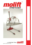
- a patient lifter from
Table of contents
General advice.................................................. 3
Explanation of symbols................................ 3
Before using the patient lifter....................... 3
Responsability.............................................. 3
Accessories..................................................... 16
Lifting sling................................................. 16
Sling size guide. ...................................... 16
Easy Scale........................................................ 17
Main parts.................................................... 5
Safety devices.............................................. 5
Safety instructions...................................... 17
Cleaning..................................................... 17
Start-up...................................................... 17
Weighing.................................................... 17
Error messages.......................................... 18
Changing the unit (kg <-->Lb).................... 18
Enhanced functions (Interactive mode)...... 18
Setting/Modifying the OFF time (Power Off)..
18
Filter settling / filter change........................ 19
Technical data................................................... 6
Maintenance. ................................................... 20
Safety precautions........................................... 4
General........................................................ 4
If defects or faults occur............................... 4
Lift and transfer............................................ 4
About the product............................................ 5
Assembly / disassembly................................. 7
Assembly and use of charger....................... 7
Assembly...................................................... 7
Checklist before use..................................... 7
Disassembly................................................. 7
Operation............................................................ 8
Battery care.................................................. 8
Battery capacity............................................ 8
Battery types and chargers.......................... 8
Operating the hand control........................... 8
Emergency stop and lowering...................... 9
Lifters with manually lowering function......... 9
Lift and transfer............................................ 9
Use of spread legs..................................... 10
Using lifting slings...................................... 10
Lift and movement to and from bed............11
Lift from bed.............................................11
Lift to bed................................................ 12
Removing the sling. ................................. 12
Lift and transfer to and from floor............... 12
Alternative lift 1........................................ 12
Alternative lift 2........................................ 13
Lowering to floor...................................... 13
Lift and transfer to and from (wheel)chair.. 13
Lift and transfer from (wheel)chair. ............ 13
Lift and transfer to (wheel)chair................. 14
Removal of sling...................................... 14
Bathing....................................................... 14
Toileting...................................................... 14
Alternative............................................... 15
Page of 24
Daily maintenance...................................... 20
Monthly maintenance................................. 20
Fault finding................................................ 20
Service / yearly maintenance .................... 20
IMPORTANT!
The patient lifter is only meant to be used by
qualified personnel.
The manual shall not be handed over, or made
available to, any unauthorised third party, without a prior written consent from Molift AS.
Exciting laws, conventions and agreements
protects all documents. No extract of this documentation can be reproduced, used or transferred without prior written consent from Molift
AS. Violation of these regulations may lead to
judicial repercussions and economic responsibility. Industrial rights are reserved.
Molift AS
Ole Deviksvei 44
0668 OSLO, Norway
Teleph:(+47) 40001004
Fax: (+47) 40001008
www.molift.com
[email protected]
E Rev. H/ 09/2006
General advice
Responsability
Please read these operating instructions carefully
This user manual contains important safety instruc- before putting the product into operation. We astions and information regarding the use of the lifter. sume no liability for damage or malfunctions reCarefully read the manual before using the lifter in sulting from failure to comply with the instrucorder to be familiar in the function and use of the tions. Warranty claims must be made immediately
lifter.
on detecting the defect. Remember to quote the serial number. Consumable parts are not subject to the
Explanation of symbols
warranty.
This symbol is used to point out instructions
and information related to work place safety
where injury may occur if the information is
disregarded or ignored. Follow these instructions, be careful and attentive at all times.
This symbol indicates important information
regarding the use of the equipment. If not
taken into consideration, it may lead to damage or functional defects to the lifter or other
equipment.
This symbol indicates important and useful
information. If taken into consideration, it
will help the operator of the lifter to work efficiently. It may help simplify routines and to
explain complicated facts.
Before using the patient lifter
Before using a patient lifter, the operator must be
trained accordingly. Practice lifting a colleague, and
be lifted by others. It is important not only to know
how to move another person using the lifter, but also
how it is to be lifted. Try out and practice using all
the relevant slings for the different types of lifter and
movement you may encounter. Before lifting a person, you should explain the procedure.
When using the lifter, it’s also important to use the
correct sling and accessories according to:
•
•
•
•
type of disability
size
weight
type of movement
All technical information, data and instructions for
operation contained in these operating instructions
were up-to-date at time of print and are compiled
on the basis of our experience and to the best of our
knowledge. We reserve the right to incorporate technical modifications within the scope of further development of the product described in this manual.
No claims can be derived from the information, illustrations or descriptions contained in these instructions. We assume no liability for any damage or
malfunction caused by operating errors, non-compliance with these operating instructions or inappropriate maintenance. We expressly point out that only
genuine Molift AS spare parts and accessories approved by us may be used. For safety reasons, the
fitting and use of spare parts or accessories, which
have not been approved, and unauthorised modification or conversion of the product, are not permitted. Molift AS will accept no liability for damages
resulting from such acts.
With the exclusion of product liability, Molift AS
is liable for faults or omissions on its part within
the scope of the warranty obligations stated in the
purchase contract. Claims for damages are excluded, irrespective of the legal reason from which such
claims are derived. Only documentation belonging
to the actual equipment is valid.
Any failure to comply with the safety regulations
and precautionary measures stated in these operating instructions renders the declaration of conformity supplied with the system in accordance with
Council Directive (93/42/EEC) concerning medical
devices invalid.
Page of 24
Safety precautions
General
Before putting a Molift SMART into operation, the
operator must ensure that the lifter and accessories
are in good working order, especially with regards to
safety. All instruction and information in this manual regarding safety and general precautions must be
read, understood and followed carefully. Any disregard to these precautions may result in personnel injury or damage to the equipment. The lifter must be
taken out of service immediately, or not returned to
service, if faults and/or irregularities that may have
influence on the safety are discovered.
Injury to personnel or equipment may occur if Molift
SMART is used in an incorrect manner and if:
•
•
•
•
covers are removed by unauthorised personnel
used incorrectly
insufficient maintenance
load exceeds maximum limit. The maximum
load stated in this manual and on the lifter is the
maximum load
• unauthorised repair of electrical devices or cables
Lift and transfer
The patient lifter may tip over if used incorrectly! Ignorance of warnings and instructions may lead to personnel injury. Read instructions carefully before attempting to lift
anyone.
Safety devices and -equipment must not be removed, disabled or in any other way altered. A
Molift SMART shall only be used when all safety
devices and equipment is in place and fully operational.
Several factors have to be considered during movement of the lifter:
The lifter is designed for use in room temperature, +10 to +40 °C. This should be • the user shall sit as low as possible facing the
taken into consideration when transporting
lifting column
the lifter, and therefore keeping it in a tem- • the user should rest their feet on the chassis
perate part of the vehicle. Alternatively, the
lifter must rest in a temperate room until the Stand to the side of the user when lifting. Ensure that
equipment has achieved proper working tem- arms and legs are clear of the lift, chair, bed etc. Try
perature.
to maintain eye contact with the user - this will help
the user feel safe and comfortable.
If defects or faults occur
The lifter must be switched off immediately if one
Pay close attention to your actions. Ensure
that all four loops of the sling are securely
of the following conditions occur;
fastened to avoid the user slipping or falling
• damage to electrical devices or cables, or damage
to parts of electrical insulation
Use the drive handle to manoeuvre the lift, do
• damage or failure on safety devices
NOT attemt to manoeuvre the lift by pushing
on the lifting arm, actuator or patient.
If the lifting movement does not start when
the corresponding button is pressed, please
Molift slings shall ONLY be used to lift perconsult the fault finding table in the maintesons. NEVER use the sling to lift and/or move
objects of any kind.
nance chapter to locate the fault.
Page of 24
E Rev. H/ 09/2006
About the product
The lifting arm is joined to the top of the lifting column and the battery driven actuator provides the
Molift SMART is a foldable mobile lifter intended lifting movement. At the end of the lifting arm, you
for lifting and transferring personnel. The lifter is will find the suspension with four hooks to attach
made out of light materials, it has castors and a bat- the sling. The suspension rotates freely, allowing the
tery. It is therefore ideal for mobile care units, such Molift SMART to be used at any angle.
as home care personnel who has a need for lifting
capabilities without fixed or stationary lifting devic- Safety devices
es present in every home. The lifter has intelligent Molift SMART is equipped with several safety deelectronics with softstart, two speeds and a counter vices, which are intended to prevent damage to perto register the number of lift cycles.
sonnel and equipment in the case of incorrect use.
Main parts
• The lifter has an overload sensor preventing the
The lifter is built around a chassis unit comprislifter to be operated with more the maximum
ing a lifting column fixing bracket, rear castors and
load. If the load exceeds the maximum limit, the
spreading mechanism for the legs. The lifting collifter will stop the movement.
umn can be rotated in the fixing bracket, allowing • The lifter has a safety feature to prevent the liftthe lifting column to fold down to a horizontal posiing arm and suspension from squeezing a user if
tion during transport, in addition to the near vertical
lowered to much. The actuator will not produce
position used during lifting.
any force in downward movements.
• The legs are folded together during transport to
A drive handle used for transferring the lifter is situmake the lifter as small as possible. When assemated at the top of the lifting column. A battery holdbling the lift, the legs must be spread to working
er containing the control electronics is placed at the
position. A safety feature will prevent the lifting
right side of the lifting column. The battery holder
column to be fixed in the bracket before the legs
also features an emergency stop button, LED indiare spread beyond transport position.
cator, emergency lowering switch and contacts for • The suspension has safety hooks to prevent the
the hand control and actuator. The adjustable legs
sling loops to fall off.
are operated by pedals and give the operator the pos- • The electronics are disabled if the temperature
sibility to adjust the width of the lifter to different
rises beyond a critical limit.
needs and situations.
Drive handle
Lifting arm
Actuator
Lifting column
Battery holder /
control electronics
Suspension
Chassis
Emergency stop
Adjustable legs
Pedals for
adjusting the legs
Lifting column fixing
bracket
Page of 24
Technical data
Lifting capacity (maximum):
Weight, total:
Lifting height:
Material:
Height of legs:
Motor:
Measurement, transport:
Ex. battery; 25 kg / incl. battery: 25,8 kg
Battery:
Steel and aluminium
12 VDC
14,4 V NiCd 1,9 Ah or 14,4 V NiMH 2,2
Ah, Molift Power Pac
Page of 24
150 kg
0 - 750 mm below user
Max 110 mm
1160 x 475 x 350 mm (LxWxH)
Measurement, assembled:
1160 x 1060 mm (LxW)
Measurements in illustrations below are in millimetres.
E Rev. H/ 09/2006
Assembly / disassembly
To be able to operate the lift, the operator must have
good knowledge of the lift, including assembly, disassembly and preparation before use.
Ensure that the lifting column is properly
fixed and that the locking handle at the base
of the lifting column is properly tightened.
Disassembly
• Run the lifting arm all the way down while holdAssembly and use of charger
ing the suspension up towards the lifting arm alThe battery charger shall be mounted on a vertical
lowing the suspension to be placed into the transwall surface close to a power outlet. The charger
port hook.
shall be connected to the power outlet at all times.
Molift AS tests and charges all batteries before packing and shipment. However, all batteries must be charged before use.
Assembly
• Open the bag (if used) and lift out the lifter
• Remove the transport elastic and spread the legs
to initial operating position
• Lift up and rotate the lifting column and press it
down into the bracket as shown in the illustration
below (1).
• Remove the battery from the lifter to avoid it
falling out during transportation.
The control electronics are active as long as
the battery is placed in the holder. If the lifter
is to be stored for a longer period, the battery
should then be removed (or emergency stop
activated) to avoid unnecessary discharge of
the battery.
• Open the locking handle, lift up the lifting column (grab with both hands and lift straight up)
and rotate it to transport position.
• Fix the lifting column in place by rotating the
locking handle down (2).
• Insert the battery into the battery holder and verify that the emergency stop button isn’t activated.
• Lift the suspension out of the transport hook and
raise the lifting arm up to desired working elevation.
Do not start to run the lifting arm before the
suspension is released!
Checklist before use
• Check that the lifter has no apparent damage or
other faults
• Check that you have sufficiently charged batteries to complete the task you have planned
The lifter can be split into two parts by lifting
the column from the chassis completely. The
lifting column/-arm and the chassis with legs
are then separate parts.
Be careful not to get legs/arms/hands wedged
between the parts when folding down the lifting column/-arm.
• Fasten the hand control to the driving handle
• Press the legs together and secure legs and lifting
column/-arm with the transport elastic.
• Put the lifter into the bag.
Page of 24
Operation
The chargers have different ways of showing the
status of the charging process.
Battery care
Molift PowerPac system is a battery with a 14,4 V •
NiCd-charger
cell unit that is placed in the battery holder on the The charger has a LED indicating the status of the
lift. A charger is also supplied to charge the battery battery as described below:
whenever needed. This battery system is the same LED
Mode
Output
on all of Molift’s mobile lifts. The power cable of Yellow
No battery
25 V
the charger should be connected to the power outlet Yellow
Initalization (10 sec)
100 mA
at all times (verify that the charger is suitable for the
Orange
Fast charge
1,8 A
local power system voltage). Place the battery in the
Green/yellow
Top-off charge
270 mA
holder according to the arrow markings. Press the
Green
Trickle charge
100 mA
battery gently down to ensure good contact between
Orange/green
Error
100 mA
battery and charger.
Battery capacity
It is recommended that NiCd batteries are
placed in the charger when not in use. RegA LED (Light Emitting Diode) is situated on the batularly (each 10 times) the battery should be
tery holder. If the voltage of the battery falls below
used until the charging indicator on the lifter
a certain level, the diode will change to orange, inglows, before charging the battery.
dicating the need for charging. There is still enough
capacity to perform 3-5 lift cycles (75 kg) at this
point. If the battery is discharged during a working • NiMH-charger
session, it’s recommended to have two batteries, so The charger has two diodes - a green and a red. The
a second charged battery is available when needed. red diode will glow as soon as the battery is placed
in the charging unit and maximum charging current
If the battery is discharged during a lift, it is is applied. The green diode will start to glow when
always enough power to lower the user down the battery is fully charged and the charger switchagain.
es to maintenance charging. If the charger can’t
detect fully charged battery after about 8 hours, a
Battery types and chargers
built in timer will force the charger to maintenance
Molift PowerPac can be used with two kinds of bat- mode to avoid overcharging.
teries; NiCd and NiMH.
Operating the hand control
The battery and charger types must not be The hand control has four buttons (high/low speed
mixed. Use of wrong charger to battery type up and high/low speed down) which gives the opermay cause overheating and damage to the ator excellent control over the lift.
Powerpac
High speed up
Be aware that these two batteries have different chargers. Follow the instructions printed
on the battery.
High speed down
It’s not possible to overcharge the batteries, Low speed up
but to ensure optimal performance throughout the lifetime of the battery, we recommend Low speed down
that the battery is allowed to rest for a couple of minutes after charging to cool down The control electronics has a power saving feature,
before use. It is also important that fully which puts the system into stand by after about two
charged batteries are not charged without minutes of inactivity.
beiing used.
Page of 24
E Rev. H/ 09/2006
Emergency stop and lowering
Lift and transfer
All of the Molift patient lifts are equipped with The suspension shall always be positioned across
emergency stop and lowering. The emergency stop the user as shown left in the illustration below.
will cut the power to the actuator, and is situated on
the battery holder on the lifting column. Turning it
clockwise until it pops out will reset the emergency
button.
It is possible to perform an emergency lowering of
the lifting arm in case of a general malfunction of
the control electronics. The button can be found on
the battery holder under a yellow sticker seal. If you
need to perform an emergency lowering, move the
lifter to a suitable location to lower the user.
• Press the emergency stop button and leave it.
• Puncture the seal and press the emergency lowering button. The lifting arm will then perform a
smooth downward movement.
• If the lifter still do not work, change battery and
try the emergency lowering procedure again.
• If it still does not work, the suspended user must
be lifted out manually. Request assistance.
When using slings intended for two point suspension, the suspension shall be used diagonally, i.e. loops from the sling shall be fastened on hooks diagonally opposite.
Try to position the user as low as possible (preferably resting the feet on the chassis) when transferring
the lifter with a suspended user. In this way, the centre of gravity will be as low as possible and therefore reducing the risk of instability. The lifter should
Contact your Molift service partner if the be manouvered with spread legs in outer position to
reason for the failure causing an emergen- achieve the highest possible stability.
cy lowering is unknown or if it is a result of
failed components or parts.
Be careful during movement - the suspended user
may swing somewhat during turns, stops and starts.
Lifters with manually lowering function
Be particularly careful when manoeuvring close to
The manually lowering function on the actuator is furniture to prevent the suspended user from collidonly to be used if the electrical lowering does not ing with these objects.
work.
The lifter shall not be used to lift or move users on sloping surfaces.
Handle for
manually lowering
Pull the red handle slightly upwards. Take
care, the lifter moves faster when activating
the handle more. The lifter will stop dead with a danger of personal injury and damage on the lifter if the handle is released
suddenly.
Avoid deep pile carpets, high thresholds, uneven
surfaces or other obstacles that may block the castors. The lifter may become unstable if forced over
such obstacles increasing the risk of tipping over.
The lifter shall only be used for movement
over short distances. It is not a replacement
for wheelchair or similar.
Page of 24
Use of spread legs
Sling without head support
Use wide legs wherever appropriate, for instance to
position the lifter around wheelchairs, toilets etc.
• To spread the legs, - press (pump) the right pedal
on the chassis.
• To narrow the legs, press (pump) the left pedal.
Sling with head support
Using lifting slings
The Easy lifting slings are, as the name indicates,
easy to use. They are washable at 80º C and autoclave at 85 ºC for 30 minutes. The plastic insert of
the head support should be removed before washing.
It is recommended to use Molift Easy slings.
Slings from other manufacturers may have
other specifications leading to unexpected
instability and possible injury to personnel.
Please see the user manual that comes with
the sling for spesific instructions.
Fold the sling as indicated above before use. The
grey side should be facing away from the user when
putting the sling in place. The sling should be held
by one hand, leaving the other free to move and support the user
Torn, cut, frayed or broken slings can fail,
resulting in serious injury to the user. Use
slings in good condition only. Destroy and
discard old, unusable slings.
Page 10 of 24
E Rev. H/ 09/2006
Lift and movement to and from bed
Lift from bed
Roll user onto her side. Put the folded sling behind
her back. The centre of the sling should be parallel
with the users spine. Roll her then onto her back.
If the user has a bed which enables raising
and lowering, it should be lowered before the
lifting starts.
Position the legs under the bed with the suspension
over the user. Be careful not to lower the suspension too low touching the user. Make sure that the
suspension is centred over the user before you start
the lifting. Remember - the castors should not be
locked.
Pull the leg loops forward and under the thighs as
shown.
When all four loops are hooked onto the suspension,
raise the user carefully.
If the user is in a hospital bed, it will help to
raise the head of the bed
Cross the loops, one through the other.
Repositioning of the user may be needed to ensure
that a safe and comfortable sitting position is attained as the user is raised. Reposition using the
handle on the back of the sling.
Page 11 of 24
Lift and transfer to and from floor
Lift and transfer from the floor is almost identical to
a lift and transfer from bed - please read this section.
There are two ways to lift from the floor.
Alternative lift 1
Raise the user until the buttocks are just above the
mattress. Lift the user’s legs and turn her so she faces the lifting column. When clear of bed, and if practical, lower the user so that her feet rest on the chassis. If possible, lower the bed before lifting. Move
the lifter away from bed.
Beware of obstructions under the bed that
can cause castors to stop or tip
Lift to bed
Place the sling as if in bed. Gently position the lifting column between the legs of the user as shown
above. The suspension shall be centred over the
user.
Lower the suspension enough to allow the sling
loops to be hooked up.
Centre the user over the bed and turn her so that the
feet point to the foot end of the bed. Lower the user
carefully. Remove the loops from the suspension.
Removing the sling
Gently pull leg section to the side, out from the user’s thighs and towards yourself. Pull the shoulder
section under the neck of the user and roll her gently
onto her side. Pull the sling away and roll her onto
her back.
Raise the user from the floor. Position user in the
sling by pulling the handle on the back of the sling.
Be careful when rolling the user onto her Turn user to face the lifting column, and place the
side. Make sure you have control over the feet on the chassis.
movement to prevent her from rolling completely over and out of the bed.
Page 12 of 24
E Rev. H/ 09/2006
Alternative lift 2
A floor based lift may also be performed by gently
positioning the users head on the chassis. Use a pillow if appropriate to protect the head and neck of the
user. Otherwise as alternative 1.
Lowering to floor
Place a pillow on the chassis or on the floor to protect the users head and neck (not necessary if you
are using a sling with head support). Otherwise as
described above.
Lift and transfer to and from (wheel)chair
Lift and transfer from (wheel)chair
Fold the sling as described in ”Using lifting slings”
The leg sections of the sling are pulled forward and
beneath the user’s thighs by the loops. The loops are
then crossed, one through the other, as shown.
If the users physique and ability allows it,
the user should be encouraged to take active
part in fitting the sling. The user can lean
forward, lift her thighs and help placing the
leg section.
Move the lifter around chair.
Lean the user forward gently, but ensure you continue to support her. Place the folded sling behind
the user’s back and push it down until it touches the
seat of the chair.
If the transfer is from a wheelchair, the
brakes must be locked to prevent the wheelchair from rolling away.
Raise/lift user above seat height, and perform the
transfer. It is not necessary to lift the person very
high.
Page 13 of 24
Lift and transfer to (wheel)chair
Manoeuvre the lifter so that the user is as far back in
the (wheel)chair as possible.
If the users physique and ability allows it,
the user should be encouraged to take active
part in fitting the sling. The user can lean
forward, lift her tights and help placing the
leg section.
If the transfer is from a wheelchair, the
brakes must be locked to prevent the wheelchair from rolling away.
Bathing
The procedure for lifting to/from the bath is in prinWhen lowering, you can use the following tech- ciple the same as for to/from bed. A special bathing
niques or a combination of them to position and get sling is used for this purpose. This sling dries quickthe user seated far back in the chair.
ly and may be washed at 80 ºC.
• push gently on the knees
• pull the loop on the back of the sling
• tilt the chair slightly backwards
Lower the user into chair, unhook sling from suspension and remove the lifter.
The lifter is not waterproof. Avoid direct exposure
to water.
Toileting
Removal of sling
Gently pull leg section to the side, out from the user’s thighs. Standing by the side of user, lean her forward - supporting with one hand. Pull sling up from
behind her back.
The Molift Easy Toilet Sling is used with the standard 4-point suspensions.
Molift Easy Toilet sling is a toilet sling with
a thicker and wider upholstery. It is also available with head-support. The Molift Easy
Toilet Comfort sling is easier to fit in narrow
environments, and is available with a separate head support
The toilet sling can be washed at 80 ºC, and is fitted
as follows:
Pulling sharply on sling may cause user to
fall forward resulting an injury. Always support the user by keeping one arm around the
user’s shoulder when fitting or removing the
sling (see illustration).
Page 14 of 24
• Insert the sling behind the users back with the
grey side away from user.
• Fasten the belt firmly around the user’s body.
E Rev. H/ 09/2006
• Place the leg section under the front part of the
thighs and pull the loops up between the thighs.
Alternative
By pulling the leg sections from the outside
and in, you will achieve a wider leg position.
• On Molift Easy Toilet Comfort, place the leg section over and down between the thighs and pull
outwards from the inner part of the thighs.
The leg sections of Molift Easy Toilet Comfort Sling are fitted to separate the legs, therefore they should not be crossed as the other
Easy slings.
• Hook the four loops on the suspension as for
other slings.
• Position the lifter around the toilet and lower the
user.
• Pull the leg sections out of the way. The sling
can be left on during bathroom use.
Page 15 of 24
Accessories
Molift Easy Toilet Sling Comfort
Lifting sling
Molift Easy Paediatric Sling
Size
No headsupport
Separate
headsupport
XXS
Art. no 3016050
Art. no 3016055
Art. no 3016000
Art. no 3016001
Size
No headsupport
With headsupport
XS
XXS
Art. no 3005050
Art. no 3006050
S
Art. no 3016100
Art. no 3016111
XS
Art. no 3005000
Art. no 3006000
M
Art. no 3016200
Art. no 3016222
L
Art. no 3016300
Art. no 3016333
XL
Art. no 3016400
Art. no 3016444
XXL
Art. no 3016500
Art. no 3016555
Easy Toilet Sling and Basic Bathing Sling for kids,
see the tables below, size XXS and XS.
Molift Easy Sling
Molift Easy Amputee Sling
Size
No headsupport
With headsupport
XS
Art. no 3025000
Art. no 3026000
Size
No headsupport
With headsupport
Art. no 3027050
Art. no 3028050
S
Art. no 3025100
Art. no 3026100
XXS
M
Art. no 3025200
Art. no 3026200
XS
Art. no 3027000
Art. no 3028000
L
Art. no 3025300
Art. no 3026300
S
Art. no 3027100
Art. no 3028100
XL
Art. no 3025400
Art. no 3026400
M
Art. no 3027200
Art. no 3028200
XXL
Art. no 3025500
Art. no 3026500
L
Art. no 3027300
Art. no 3028300
Molift Basic Sling
Size
No headsupport
With headsupport
XXS
Art. no 3021050
Art. no 3022050
XS
Art. no 3021000
Art. no 3022000
S
Art. no 3021100
Art. no 3022100
M
Art. no 3021200
Art. no 3022200
L
Art. no 3021300
Art. no 3022300
XL
Art. no 3021400
Art. no 3022400
XXL
Art. no 3021500
Art. no 3022500
XL
Art. no 3027400
Art. no 3028400
XXL
Art. no 3027500
Art. no 3028500
Bag for slings - Art. no 3048000
Transport bag for Molift SMART lifter w/batteries.
Sling size guide
A
C
B
Molift Basic Bathing Sling
Size
No headsupport
With headsupport
XXS
Art. no 3023050
Art. no 3024050
XS
Art. no 3023000
Art. no 3024000
S
Art. no 3023100
Art. no 3024100
M
Art. no 3023200
Art. no 3024200
L
Art. no 3023300
Art. no 3024300
XL
Art. no 3023400
Art. no 3024400
XXL
Art. no 3023500
Art. no 3024500
Molift Easy Toilet Sling
Easy and Basic Slings
Size
Color
code
Recomm.
weight
(Kg)
A
(cm)
B
(cm)
C
(cm)
XXL
White
230-300
86
130
68
XL
Blue
160-240
76
115
66
L
Green
90-160
66
100
64
M
Yellow
45-95
56
85
62
S
Red
25-50
51
75
60
Art. no 3033300
XS
Light blue
17-25
46
65
58
Art. no 3032400
Art. no 3033400
XXS
Pink
12-17
41
55
56
Art. no 3032500
Art. no 3033500
Size
No headsupport
With headsupport
XXS
Art. no 3032050
Art. no 3033050
XS
Art. no 3032000
Art. no 3033000
S
Art. no 3032100
Art. no 3033100
M
Art. no 3032200
Art. no 3033200
L
Art. no 3032300
XL
XXL
Page 16 of 24
Choice of sling size depends on both user weight
and shape/size of user.
E Rev. H/ 09/2006
Easy Scale
The maximum scale loading must not be exceeded. The safety requirements and the notes
on appropriate use provided by the lifter and
the system manufacturer must also be observed.
• Display segment test
(~5 seconds)
please wait
Safety instructions
Please comply with the maximum capacity of the
scale which is stated on the identification plate on
the back of the device.
• Switch on the scale
• then all segments go
off (~2 seconds)
• Automatic zeroing 1)
(~3 seconds)
• The scale is ready
to use. Now you can
weigh.
This device meets the requirements under 90/384/
EU and 73/23/EU and is interference--suppressed
1) If the initial loading of the scale (tare) exceeds20 % of the weighing range, automatin accordance with the currently valid EU directive,
ic zeroing does not take place. In this case,
89/336/EU. The device must not be modified from
tarring has to be performed manually. (See
the design or safety engineering point of view except
chapter Taring/Additive weighing.)
the supplier express agreement. Any modification
shall exclude all liability on the part of the supplier
for any damage resulting therefrom. It is strictly for- Taring / Additive weighing
bidden to carry out any repairs and soldering work Switch on the scale and wait ~10 seconds .
on the motherboards or to replace any components. Add the weight to be tared (e.g. belt)
Repairs must only be undertaken by persons who
are authorized and qualified to do so.
• Taring
Cleaning
Just wipe gently with a damp cloth, do not use any
abrasive or caustic cleaning agents.
• Now you can weigh /
weigh by addition.2)
Start-up
Unscrew the right--hand cover, insert the battery
case with batteries (4x 1.5 V-type AA) according to
the polarity indicated! Push the tray into the battery
compartment and screw the cover down again. The
scale is now ready to use.
2) Keep pressing the G/N key to toggle between the scale zero and the gross weight
Batteries do not belong in domestic waste.
Please hand in used batteries to public collection points or dispose of them through the
trade.
Weighing
Switching on / Weighing
The scale is ready to use about 10 seconds after it is
switched on. During this time, the scale must neither
be moved nor loaded
Add more of the weight to be tared
• Taring 3)
• Now you can weigh/
weigh by addition.
3)The first time the G/N key is pressed, the current total (gross) weight is displayed. Taring
occurs when the G/N key is pressed again.
You can repeat this as often as you like until
the maximum weighing range of the scale is
reached.
Page 17 of 24
Enhanced functions (Interactive mode)
Switching off
• Press the ON/OFF
key to switch off the
scale.
Error messages
Overload
Overload
Battery status
• Scale overloaded!
Please comply with
the nominal (rated)
load for the scale
(see identification
plate on the back of
the device)
Setting/Modifying the OFF time (Power Off)
• Switch on the scale and wait ~10 seconds (see
chapter switching on/raging).
• Simultaneously pressing the ON/OFF and G/N
keys enables interactive mode.
press simultaneously
Interactive mode
(Standard Function)
• Switch the scale off
and on again.
OFF time (Power Off)
• Select by repeatedly
pressing the ON/OFF key
(digit flashes):
Can only be switched off
manually (by means of the
ON/OFF key)
Switches off automatically
after 30 secs.
(only if the scale is unloaded)
Switches off automatically
after 60 secs. (only if the
scale is unloaded)
• The batteries are
flat and must be replaced!
4)Non-legal-for-trade scales can be used for
weighing for a short time after the battery symbol appears. To prevent measurement error, however, the batteries should be replaced at once.
Changing the unit (kg <-->Lb)
(Only possible with non-legal-for-trade scales.)
• Confirm the selection
with the G/N key.
.
• Switch on the scale and wait ~10 seconds
(see chapter switching on/raging).
Unit kg
At this point, you can
check or change PO by
pressing ON/OFF again
• Keep pressed for ~5 seconds
Unit Lb (American pound)
The same method is used to
change from Lb to kg.
The last unit set is retained even when the scale is
switched off.
Page 18 of 24
1 x press: Filter setting AF (see next
page)
or
2 x presses: back to
weighing mode
or
E Rev. H/ 09/2006
Filter settling / filter change
Stabilizing the weight display
• Switch on the scale and wait approx. 10seconds
(see chapter switching on/raging).
• Simultaneously pressing the ON/OFF and G/N
keys enables interactive mode.
press simultaneously
Interactive mode (Standard_Function)
Filter setting (Amplifier Filter)
• Select by repeatedly pressing the ON/
OFF key (digit flashes):
0 = Filtering switched off
1 = weak filtering:
+ very fast weight display
- unsteady display while moving
4 = average filtering (recommended):
+ fast weight display
+ steady display
8 = very strong filtering:
+ Possible to weigh unsteady people
- long waiting time until the weight or
the zero-point of the scale is displayed
steadily
• Confirm the selection and adopt the settings with the G/N key
• At this point, you can check or change
AF by pressing ON/OFF again.
• back to weighing mode²
Now you can weigh.
Page 19 of 24
Maintenance
Daily maintenance
Detergents must be pH-neutral. Do not use
solvents or strong liquids - this may damage
surfaces on the lifter. For disinfection when
needed; use isoproply alcohol. Avoid abrasive cleaning products.
Clean surfaces with a damp cloth using an appropriate detergent.
Monthly maintenance
• Remove hair and pile from the castors and verify
that the castors rotates without abnormal friction
• Verify that the contacts of the hand control and
charger is firmly in place
• Clean contact and hand control with spirit or
similar to remove grease and dirt
• Verify that the cables for the hand control, actuator and charger are intact
• Run the lifter up and down to verify that it runs
normaly and without any abnormal noise
Fault finding
Symptom
Possible cause/action
The lifting column
is wobbly
Locking handle is loose and
must be tightened or the lifting
column is out of position in the
bracket / verify position of lifting
column and tighten locking handle
Lifting arm (actuator) does not move
Battery is empty / change to a
new battery or charge battery
Emergency stop activated (button is pressed in) / turn knob
clockwise to reset
The cable/contact of the actuator
or hand control has disconnected / reconnect contact(s)
Hand control has failed / switch
to another identical control if
available or contact local service
representative for service
Defecive control electronics /
contact local service representative for service
Actuator is defective / contact
local service representative for
service
Service / yearly maintenance
If you are not able to solve the fault or problems by
yourself using this manual, please contact local authorised service representative. If you do not know
whom to contact locally, please contact your dealer
or Molift AS to get help.
Yearly service is done according to procedures in
the service manual included with the SMART lifter.
The owner is responsible to ensure proper logging
and written verification performed by authorised
service partner. The service manual has dedicated
pages for logging and signature.
Page 20 of 24
E Rev. H/ 09/2006
Page 21 of 24
WARRANTY
Molift AS hereby declares that this product is awarded up to 5 - five - year extended manufacturer’s
warranty.
It is very important to our customers and to Molift AS that our products meet all relevant quality and safety requirements according to both customer and authority demands. Molift AS develops and manufactures products with high standards of safety, quality and design, and we are continuously in a process of
keeping our products in position among the market leaders.
To make our products quality level more explicit Molift AS have introduced extended warranty time on
all of our patient lifters. A 5 - five - year* warranty against defects which might be traced back to manufacturing is offered. The extended warranty period is offered under the condition that the regulations
described here are completely fulfilled and that the product has been used according to its intentions.
The extended warranty is valid for a period of 5 - five - years starting at the date of purchase limited to
3 months after the production year/week. The extended warranty is offered in addition to the local sale
of goods act. It is mandatory that the product undergoes safety control and maintenance performed by
an authorised service partner at least every 12 months according to this service manual made by Molift
AS.
• Yearly maintenance and safety control must be performed within a maximum interval of 12 months
and for the first time maximum 12 months after date of purchase or maximum 15 months after year/
week of production.
• Molift AS will cover the cost of spare parts and labour in the warranty period for all necessary repairs caused by product defects that can be traced back to manufacturing. The repair must be performed by an authorised service partner or at Molift AS’ own workshop during the warranty period.
• All warranty repairs must be approved by your Molift supplier or by Molift AS prior to the repair.
• The owner of the product is responsible for establishing the service agreement, and the cost for the
annual safety control and maintenance.
• The service manual has one page for every 12 months containing checkpoints for maintenance and
safety control. The extended warranty is valid only with signature and/or stamp by authorised service
partner including service partner’s signed label with authorisation no. on product.
* Normal warranty is 12 months. This still applies for slings, hand control, batteries and paint.
Gjøvik 28.08.2006
Molift AS
__________________
Geir Olav Farstad
Managing Director
Page 22 of 24
E Rev. H/ 09/2006
DECLARATION OF CONFORMITY
Molift AS
Ole Deviksvei 44
0668 OSLO
NORWAY
Telephone: + 47 40 00 10 04
hereby declare that:
Molift SMART patient lifter
and that the accessoires used only together with this product
Year: 2006
are in conformity with:
• The Council Directive concerning medical devices (93/42/EØF)
and according to this classified as medical equipment class 1
Molift SMART is manufactured in conformity with the following national or
international standards that also might implement a harmonised standard:
• ISO10535 Hoists for the transfer of disabled persons - Requirements and test methods
• ISO 14971 Medical equipment - Risik analysis
Notified fody:
Hjelpemiddelinstituttet
Gregersensvej
DK-2630 Taastrup
Denmark
Tel: + 45 43993322
Title:
Name:
Company:
NEMKO AS
Gaustadalleen 30
N-0314 OSLO
Norway
Tel: + 47 22960342
Managing Director
Geir Olav Farstad
Molift AS
28.08.2006
Date
Signature
Page 23 of 24
At times with increasing demand for efficiency in the healthcare sector and growing
focus on patients needs, it is easy to neglect the needs of the carer. The need to give
better help and caring avoiding heavy lifting situations, avoiding putting your own
back at risk, without being completely exhausted after work and still have some surplus energy when the workday is over.
This is the insight that drives us at Molift. The company was started 20 years ago by a
man who through his own experience saw the need for lifting and moving patients in
an effective and comfortable way - for both patient and carer.
We have since then delivered products that compliment the natural movements of the
body, that is both simple and intuitive to use. Products designed to give the patient
a better life in addition to providing the carer with real support and optimum work
enjoyment.
This is the true meaning of; Molift - designed for life
Molift AS
Ole Deviksvei 44
N - 0668 OSLO
Norway
Telephone: (+47) 4000 1004
Fax: (+47) 4000 1008
www.molift.com
[email protected]