1
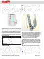
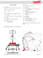
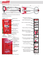
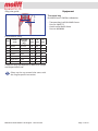
BM09201 Molift SMART 150 English - Rev B/10/09
Page 1 of 20
Table of content
Maintenance....................................... 16
Before using the patient lifter..................... 3
Explanation of symbols.............................. 3
Cleaning................................................... 16
Monthly inspection................................... 16
Periodic inspection................................... 16
Service..................................................... 17
General Safety precautions..................4
Checklist periodic inspection............ 18
General...................................................... 4
Lift and transfer.......................................... 4
Warranty.............................................. 19
About Molift Smart................................3
Assembly / disassembly........................5
Unpacking.................................................. 5
Assembly.................................................... 5
Storage....................................................... 6
Disassembly............................................... 6
Molift Smart 150 - use...........................7
Checklist before use..............................7
Lift and transfer.....................................8
Use of spread legs..................................... 8
Safety devices........................................9
Emergency stop and lowering.................... 9
Operation............................................ 10
Battery charger......................................... 10
Battery capacity........................................ 10
Electronics................................................ 10
Technical data..................................... 11
Labelling................................................... 12
Accessories.......................................... 13
Lifting sling............................................... 13
Equipment........................................... 14
Transport bag .......................................... 14
Troubleshooting................................. 15
BM09201 Molift SMART 150 English - Rev B/10/09
Page 2 of 20
About Molift Smart
Explanation of symbols
Molift Smart 150 is a foldable mobile lifter intended for lifting and transferring personnel. The lifter
is made out of light materials, it has castors and a
battery. It is therefore ideal for mobile care units,
such as home care personnel who has a need for
lifting capabilities without fixed or stationary lifting devices present in every home.
The Molift Smart 150 with accessories as described in this manual are CE marked according
to the Council Directive concerning medical devices (93/42/EEC). The lifter is classified as medical equipment class 1, and tested and verified by
a third party, according to standards IEC 60601-1,
IEC 60601-1-2 and NS-EN ISO 10535:2006
Before using the patient lifter
Before using a patient lifter, the operator must be
trained accordingly. Practice lifting a colleague,
and be lifted by others. It is important not only to
know how to move another person using the lifter,
but also how it is to be lifted. Try out and practice
using all the relevant slings for the different types
of lifter and movement you may encounter. Before
lifting a person, you should explain the procedure.
When using the lifter, it’s also important to use the
correct sling and accessories according to:
•
•
•
•
This symbol is used to point out instructions
and information related to work place safety
where injury may occur if the information is
disregarded or ignored. Follow these instructions, be careful and attentive at all times.
This symbol indicates important information
regarding the use of the equipment. If not
taken into consideration, it may lead to damage or functional defects to the lifter or other
equipment.
This symbol indicates important and useful
information. If taken into consideration, it
will help the operator of the lifter to work efficiently. It may help simplify routines and to
explain complicated facts.
type of disability
size
weight
type of movement
The lifter must be taken out of service immediately, or not returned to service, if faults
and/or irregularities that may have influence
on the safety are discovered.
BM09201 Molift SMART 150 English - Rev B/10/09
Page 3 of 20
General Safety precautions
The patient lifter may tip over if used incorrectly! Ignorance of warnings and instructions may lead to personnel injury. Read instructions carefully before attempting to lift
anyone.
General
Before putting a Molift Smart 150 into operation,
the operator must ensure that the lifter and accessories are in good working order, especially with
regards to safety.
Pay close attention to your actions. Ensure
that all four loops of the sling are securely fastened to avoid the user slipping or falling
A Molift Smart 150 shall only be used when all
safety devices and equipment is in place and fully
operational.
Use the drive handle to manoeuvre the lift, do
NOT attempt to manoeuvre the lift by pushing on the lifting arm, actuator or patient.
The lifter must be taken out of service immediately, or not returned to service, if faults and/or irregularities that may have influence on the safety are
discovered.
Torn, cut, frayed or broken slings can fail, resulting in serious injury to the user. Use slings
in good condition only. Destroy and discard
old, unusable slings.
The lifter is designed for use in room temperature, +10 to +40 °C. This should be taken into
consideration when transporting the lifter,
and therefore keeping it in a temperate part
of the vehicle. Alternatively, the lifter must
rest in a temperate room until the equipment
has achieved proper working temperature.
Molift slings shall ONLY be used to lift persons. NEVER use the sling to lift and/or move
objects of any kind.
Molift Smart 150 should not be run constantly for more than 2 minutes during 18 minutes.
The lifter has an expected lifetime of 10 years
or 30 000 lifts with max load (SWL), when all
recommended service is performed.
Injury to personnel or equipment may occur if
Molift Smart 150 is used in an incorrect manner
and if i.e:
• covers are removed by unauthorised personnel
• used incorrectly
• insufficient maintenance
• load exceeds maximum limit. The maximum
load stated in this manual and on the lifter is
the maximum load
• unauthorised repair of electrical devices or cables
If the lifting movement does not start when
the corresponding button is pressed, please
consult the fault finding table in the maintenance chapter to locate the fault.
Several factors have to be considered during
movement of the lifter. Stand to the side of the
user when lifting. Ensure that arms and legs are
clear of the lift, chair, bed etc. Try to maintain eye
contact with the user - this will help the user feel
safe and comfortable.
Lift and transfer
The Molift Smart 150 has a Safe Working
Load on 150 kg, meaning that it is tested
and approved for lifting of patients up to 150
kg. Attempts to lift patients above SWL may
damage the lifter and lead to personal injury.
BM09201 Molift SMART 150 English - Rev B/10/09
Medical electrical equipment requires special precautions regarding electromagnetic compatibility (EMC) and must be installed
and used according to instructions contained in this manual. Portable or mobile radio communication equipment may affect
the medical electrical equipment.
Page 4 of 20
Assembly / disassembly
Unpacking
• The lifter comes in one cardboard box. Verify
that the box has no apparent damage. If damaged, check the content and contact your dealer for assistance if components are damaged.
• The box contains one complete Molift Smart
lifter with hand control, battery and battery
charger.
Assembly
The column must be
placed in the bottom of
the bracket on chassis as
shown on the illustration
to the left.
• When the column has placed itself in the bottom of the bracket, it should be fixed with the
locking handle on the back of the chassis. Push
the locking handle down and make sure the
column is properly fixed.
The battery must not be in the battery holder
during assembly!
• Remove the transport elastic and spread the
legs to working position (maximum width).
Transport position
• Lift the suspension out of the transport hook.
Working position
Max width
The legs must be spread to working position
before the column can be mounted.
• Lift up the lifting column and slide it into the
bracket on the chassis.
Do not start to run the lifting arm before the
suspension is released!
• Insert the battery into the battery holder and
verify that the emergency stop button isn’t activated. Run the lifting arm up and down without load to verify that it is working properly.
Check that the lifter is mounted correctly with
no loose part or damages. Ensure that the
lifting column is fixed properly, and that the
legs do not move inside parallel position.
Checklist after mounting.
• Check the lifter according to the checklist before use on page 7.
BM09201 Molift SMART 150 English - Rev B/10/09
Page 5 of 20
Disassembly
• Run the lifting arm all the way down while
holding the suspension up towards the lifting
arm allowing the suspension to be placed into
the transport hook.
The lifter can be split into two parts by lifting
the column from the chassis completely. The
lifting column/-arm and the chassis with legs
are then separate parts.
Be careful not to get legs/arms/hands wedged
between the parts when folding down the
lifting column/-arm.
• Fasten the hand control to the driving handle
• Press the legs together and secure legs and lifting column/-arm with the transport elastic.
• Put the lifter into the bag.
On lifters with scale, place the suspension
carefully beside the column to avoid the scale
to get squeezed.
• Remove the battery from the lifter to avoid it
falling out during transportation.
The control electronics are active as long as
the battery is placed in the holder. If the lifter
is to be stored for a longer period, the battery
should then be removed (or emergency stop
activated) to avoid unnecessary discharge of Storage
the battery.
For long time storage it is recommended that the
battery is removed and the emergency stop but• Open the locking handle, lift up the lifting colton is activated. Storage conditions should be beumn (grab with both hands and lift straight up) tween
Molift Group AS,
106 kPa
and fold the column down to transport posiOle Deviksvei 44,
tion.
Pressure:0668
50 -Oslo
106 kPa
Humidity:Norway
20 - 90 %
(+47) 4000 1004
Temperature:
0 - 45 °C
www.molift.com
50 kPa
90 %
45°C
0°C
20 %
Labeling outside on every cartoon with Molift lifter or accessories/spare parts
Size on label ca 105x75 mm
Black printing directly on cartoon
Alternatively the labels can be printed on a A4 8 labels sheet (black printing on
Note! Only page 2 for printing on sheet with 8 labels
BM09201 Molift SMART 150 English - Rev B/10/09
Page 6 of 20
Molift Smart 150 - use
Checklist before use
The Molift Smart 150 hand control has two but- 1.Check that the lifter has no apparent damage
tons (up and down). In addition there is a diode
or other faults.
which gives a light if the battery needs charging.
2.Check that there are no loose parts, and ensure
that the lifting column is properly fixed and
that the locking handle is properly tightened.
Battery lamp
Up
3.Check that the legs
are moving in working
position only, meaning that the legs do
Down
not move inside parallel position with the
column mounted (se
fig A).
4.Check that the suspenThe legs are adjusted with pedals on the chassis.
sion is released from
Battery
the transport hook.
Battery lamp
5.Check that the emerFig A
gency stop button is
not activated and that the lifter is functioning.
Electrical emer6.Check
that you have sufficiently charged batgency lowering
teries (that the battery diode on hand control
and chassis does not light).
Emergency stop
7.Check that the service lamp gives a green light.
If yellow or red light, send lifter to service.
8.If there are any faults or irregularities, the lifter should be taken out of service immediately
and marked “out of order”. Contact your service
partner or local Molift representative.
Lifting arm
Drive handle
Suspension
Lifting column
Battery
Lifting motor
Battery holder /
control electronics
Emergency stop
BACK
Chassis with
lifting column
fixing bracket
BM09201 Molift SMART 150 English - Rev B/10/09
Adjustable legs
FRONT (forwards direction of travel)
Page 7 of 20
Lift and transfer
Use of spread legs
Use wide legs wherever appropriate, for instance
The suspension shall always be positioned across to position the lifter around wheelchairs, toilets
etc.
the user as shown left in the illustration below.
• To spread the legs, press (pump) the right pedal on the chassis.
• To narrow the legs, press (pump) the left pedal.
Left pedal,
legs in
Check that the sling is properly fastened to
the suspension to make sure the patient is nor
sliding or falling out
When using slings intended for two point
suspension, the suspension shall be used diagonally, i.e. loops from the sling shall be fastened on hooks diagonally opposite.
Right pedal,
legs out
Try to position the user as low as possible (preferably resting the feet on the chassis) when transferring the lifter with a suspended user. In this way,
the centre of gravity will be as low as possible and
therefore reducing the risk of instability. The lifter
should be manoeuvred with spread legs in outer
position to achieve the highest possible stability.
On carpet floors you might find it difficult to
manoeuvre the legs with a patient in the lifter. It is recommended, if possible, to adjust
the legs before suspending the patient in the
lifter. Alternatively you might try to move the
lifter at the same time as pressing the pedals
for leg adjustment.
Be careful during movement - the suspended user
may swing somewhat during turns, stops and
starts. Be particularly careful when manoeuvring
close to furniture to prevent the suspended user
from colliding with these objects.
The lifter shall not be used to lift or move users on sloping surfaces.
Avoid deep pile carpets, high thresholds, uneven
surfaces or other obstacles that may block the castors. The lifter may become unstable if forced over
such obstacles increasing the risk of tipping over.
The lifter shall only be used for movement
over short distances. It is not a replacement
for wheelchair or similar.
BM09201 Molift SMART 150 English - Rev B/10/09
Page 8 of 20
Safety devices
Electrical emergency lowering
It is possible to perform an emergency lowering of
Molift Smart 150 is equipped with several safety the lifting arm in case of a general malfunction of
devices, which are intended to prevent damage to the control electronics. The button can be found
personnel and equipment in the case of incorrect on the battery holder. If you need to perform an
emergency lowering, move the lifter to a suitable
use.
location to lower the user.
• The lifter has an overload sensor preventing
the lifter to be operated with more the safe
working load, 150 kg. If the load exceeds the
• Press the emergency lowering button. The liftSWL, the lifter will stop the movement.
ing arm will then perform a smooth downward
• The lifter has a safety feature to prevent the liftmovement. The emergency stop button can
ing arm and suspension from squeezing a user
not be activated when performing electrical
if lowered too much. The actuator will not proemergency lowering.
duce any force in downward movements.
• If the lifter still do not work, change battery
• The legs are folded together during transport
and try the emergency lowering procedure
to make the lifter as small as possible. When asagain.
sembling the lift, the legs must be spread to
• If it still does not work, the suspended user
working position. A safety feature will prevent
must be lifted out manually either by using the
the lifting column to be fixed in the bracket bemanual lowering function or by requesting asfore the legs are spread beyond transport posisistance.
tion.
• The suspension has safety hooks to prevent the Manually emergency lowering
sling loops to fall off.
The manually lowering function on the actuator is
• The electronics are disabled if the temperature only to be used if the electrical lowering does not
rises beyond a critical limit. Wait until the lifter
work.
has cooled down before using it again.
Emergency stop and lowering
Contact your Molift service partner if the reason for the failure causing an emergency lowering is unknown or if it is a result of failed
components or parts.
Emergency stop
The emergency stop will cut the power to the actuator, and is situated on the battery holder on the
lifting column. Turning it clockwise until it pops
out will reset the emergency button.
Electrical
emergency
lowering
Pull the red handle slightly upwards. Take
care, the lifter moves faster when activating the handle more. The lifter will stop dead
with a danger of personal injury and damage
on the lifter if the handle is released suddenly.
Emergency
stop
BM09201 Molift SMART 150 English - Rev B/10/09
Page 9 of 20
Operation
Battery charger
Molift Smart 150 is supplied with a battery with a
14,4 V cell unit that is placed in the battery holder on the lift. A charger is also supplied to charge
the battery whenever needed. The charger can be
mounted on a wall surface or placed on a table.
If the battery is discharged during a lift, it is
always enough power to lower the user down
again.
New batteries will not achieve full capacity before it has been fully charged and discharged a couple of times.
Electronics
Place the battery in the holder according to the
arrow markings. After a few seconds the charger
LED will change from yellow to orange, indicating
that the battery is charging. When the LED gives a
constant green light the battery is fully charged.
There is a counter implemented in the electronic
system of the lifter, registering the number of lifts.
The charger LED indicate the status of the battery This number can be read by using the Molift Servias described below:
cetool, and a service lamp indicates when the lifter needs service consisting of exchange of the liftLED
Mode
ing motor. See the chapter “Maintenance”.
Yellow
No battery
Yellow
Initialization (10 sec)
Orange
Fast charge
Green/yellow
Top-off charge
Green
Trickle charge
Orange/green
Error
Battery capacity
The battery lamp on the hand control will illuminate if the voltage of the battery falls below a certain level, indicating the need for charging. There
will also be an audible signal There is still enough
capacity to perform 3-5 lift cycles (75 kg) at this
point. The battery lamp on the battery holder illuminates only if the handcontrol unit is disconnected and the battery needs charging.
The electronic system has a power save-function
which makes the system sleep after a while with
no activity. All lights will go out. Activate the system by pushing one of the buttons on the hand
control.
If the lifter is run up and down constantly for a
longer period, the electronics may be overheated
and the lifter will stop. Wait until the lifter is cooled
down enough for further use.
BM09201 Molift SMART 150 English - Rev B/10/09
Discarded lifters and batteries should be handled as electronic waste and collected separately according to local laws and regulations.
Page 10 of 20
Technical data
Lifting height:
0 - 750 mm below user
Weight, total:
Lifting speed:
Ex. battery; 25 kg / incl. battery: 25,8 kg
Material:
Motor:
Battery:
Steel and aluminium
60 mm/sec
Sound level, max A-weighted sound power level:
LWA = 49,4 dB
Operating forces:
12 VDC
Buttons on hand control: 1,5 N
Foot pedal: max 300 N
14,4 V NiMH 2,2 Ah, Molift Power Pac
Height of legs:
Mascot type 2215, 10-22 cells NiCd/NiMH
Turning diameter:
IPX4
Measurement, transport:
40
Measurement, assembled:
Battery charger:
Max 110 mm
Protection:
1300 mm
Number of lifts with fully charged battery:
1160 x 475 x 350 mm (LxWxH)
Safe Working Load (SWL):
1160 x 1060 mm (LxW)
150 kg (330 lbs)
Measurements in illustrations below are in millimetres.
Measurements with lifter in working position
700
240
BM09201 Molift SMART 150 English - Rev B/10/09
Page 11 of 20
Measurements with lifter in transport position
Labelling
The main label is placed on the column bracket on
the left side of the chassis.
Nominal battery
voltage
Molift Smart 150 short
guide for mounting
Model name
READ USER MANUAL!
Safe Working Load
Lifter in transport position
1
Spread legs
2
Raise the lifting column
3
Part number and
year/week of
manufacturing
MAX
Serial number /
bar code
Make sure the column is
placed correct in bottom
of the chassis
Manufacturer
Type B
Application
Read user
manual
Separate waste
collection
For indoor
use
4
Close the locking handle
to secure the column.
5
Control lifter according to checklist on page 18
Release the suspension
from transport hook.
6
Periodical inspection each 12
month
Designated area
for calendar and
signed label for
periodical inspection
Check lifter before use
(checklist on page 7)
Control label on right side on chassis
CONTROL
Lifter is ready for use
Choose correct sling and
check for damage.
READ USER
MANUAL!
BM09201 Molift SMART 150 English - Rev B/10/09
Make sure sling is attached correctly. Pay
attention while lifting.
Page 12 of 20
Accessories
Lifting sling
Molift Easy Toilet Sling
Size
No head support
With head support
XXS
Art. no 3032050
Art. no 3033050
XS
Art. no 3032000
Art. no 3033000
S
Art. no 3032100
Art. no 3033100
M
Art. no 3032200
Art. no 3033200
L
Art. no 3032300
Art. no 3033300
XL
Art. no 3032400
Art. no 3033400
XXL
Art. no 3032500
Art. no 3033500
Molift Easy Paediatric Sling
Size
No head support
With head support
XXS
Art. no 3005050
Art. no 3006050
XS
Art. no 3005000
Art. no 3006000
Easy Toilet Sling and Basic Bathing Sling for kids,
see the tables below, size XXS and XS.
Molift Easy Sling
Size
No head support
With head support
XS
Art. no 3025000
Art. no 3026000
S
Art. no 3025100
Art. no 3026100
M
Art. no 3025200
Art. no 3026200
L
Art. no 3025300
Art. no 3026300
XL
Art. no 3025400
Art. no 3026400
XXL
Art. no 3025500
Art. no 3026500
Molift Basic Sling
Molift Easy Toilet Sling Comfort
Size
No head support
Separate
head support
XXS
Art. no 3016050
Art. no 3016055
XS
Art. no 3016000
Art. no 3016001
S
Art. no 3016100
Art. no 3016111
M
Art. no 3016200
Art. no 3016222
L
Art. no 3016300
Art. no 3016333
XL
Art. no 3016400
Art. no 3016444
XXL
Art. no 3016500
Art. no 3016555
Molift Easy Amputee Sling
Size
No head support
With head support
XXS
Art. no 3021050
Art. no 3022050
XS
Art. no 3021000
Art. no 3022000
S
Art. no 3021100
Art. no 3022100
M
Art. no 3021200
Art. no 3022200
L
Art. no 3021300
Art. no 3022300
XL
Art. no 3021400
Art. no 3022400
XXL
Art. no 3021500
Art. no 3022500
Molift Basic Bathing Sling
Size
No head support
With head support
XXS
Art. no 3027050
Art. no 3028050
XS
Art. no 3027000
Art. no 3028000
S
Art. no 3027100
Art. no 3028100
M
Art. no 3027200
Art. no 3028200
L
Art. no 3027300
Art. no 3028300
XL
Art. no 3027400
Art. no 3028400
XXL
Art. no 3027500
Art. no 3028500
Bag for slings - Art. no 3048000
Size
No head support
With head support
XXS
Art. no 3023050
Art. no 3024050
XS
Art. no 3023000
Art. no 3024000
S
Art. no 3023100
Art. no 3024100
M
Art. no 3023200
Art. no 3024200
L
Art. no 3023300
Art. no 3024300
XL
Art. no 3023400
Art. no 3024400
XXL
Art. no 3023500
Art. no 3024500
BM09201 Molift SMART 150 English - Rev B/10/09
Page 13 of 20
Equipment
Sling size guide
A
Transport bag
for Molift Smart 150 lifter w/batteries.
C
B
•
•
Transport bag (soft) for Molift Smart
Part. no: 3049175
Hard case for Molift Smart
Part. no: 0920200
Easy and Basic Slings
Size
Color
code
Recomm.
weight
(Kg)
A
(cm)
B
(cm)
C
(cm)
XXL
White
230-300
86
130
68
XL
Blue
160-240
76
115
66
L
Green
90-160
66
100
64
M
Yellow
45-95
56
85
62
S
Red
25-50
51
75
60
XS
Light blue
17-25
46
65
58
XXS
Pink
12-17
41
55
56
Choice of sling size depends on both user weight
and shape/size of user.
Please see the user manual that comes with
the sling for specific instructions.
BM09201 Molift SMART 150 English - Rev B/10/09
Page 14 of 20
Troubleshooting
Symptom
Possible cause/action
The lifting column
is wobbly
Locking handle is loose and
must be tightened or the lifting
column is out of position in the
bracket / verify position of lifting
column and tighten locking handle
The lifter only
moves in one direction/
Hand control has failed / test
with another hand control and
change if defective.
If you are not able to solve the fault or problems
by yourself using this manual, please contact local authorised service representative. If you do
not know whom to contact locally, please contact
your dealer or Molift Group AS to get help.
The control electronics has failed
/ change control electronics /
contact local representative for
service
The lifter moves
uncontrolled
Short circuit between hand control and lifter / clean the contact
to hand control with spirit to remove grease
Hand control has failed / change
hand control / contact local representative for service
Short circuit between hand control and lifter / clean the contact
to hand control with spirit to remove grease
Lifting arm (lifting
motor) does not
move
Battery is empty / change to a
new battery or charge battery
Emergency stop activated (button is pressed in) / turn knob
clockwise to reset
The cable/contact of the actuator
or hand control has disconnected / reconnect contact(s)
Hand control has failed / switch
to another identical control if
available or contact local service
representative for service
Defective control electronics /
contact local service representative for service
Lifting motor is defective / contact local service representative
for service
If you have access to more than one lifter, it may
be helpful to change parts across lifters to help
identify any faults. For instance, if you suspect the
fault to be inside the hand control, exchange the
hand control with at functional one from the other lifter to see if the problem is fixed.
BM09201 Molift SMART 150 English - Rev B/10/09
Page 15 of 20
Maintenance
Maintenance of the lifter consists of check before use, cleaning, inspection and service. Check
the lifter according to the checklist before use on
page 7, to reveal faults or errors. In regularly inspections of the lifter, which as a minimum should
be monthly inspections and annual (periodic) inspections.
Cleaning
•
•
•
•
Monthly inspection
Assemble the lifter before inspection.
• Check the lifter according to the checklist before use on page 7.
• Clean the lifter as described above.
• Verify that the contacts of the hand control and
charger is firmly in place, and verify that the cables for the hand control, actuator and charger
are intact.
• Run the lifter up and down to verify that it runs
normally and without any abnormal noise.
• The lifter must be taken out of service immediately and marked “Out of order”, or not taken
into service, if faults and/or irregularities are
discovered.
Detergents must be pH-neutral. Do not use
solvents or strong liquids - this may damage
surfaces on the lifter. For disinfection when
needed; use isopropyl alcohol. Avoid abrasive
Periodic inspection
cleaning products.
Molift recommends periodic inspection once a
year, alternatively more often if required by local
Clean surfaces with a damp cloth using an apregulations. Use the checklist for periodic inspecpropriate detergent.
Remove hair and pile from the castors and ver- tion on page 18.
ify that the castors rotates without abnormal
Inspection is to be performed by authorized perfriction.
sonnel. The owner is responsible to ensure propClean contact and hand control with spirit or
er logging and written verification of each inspecsimilar to remove grease and dirt.
tion.
Regular cleaning is recommended and should
be implemented in the suitable cleaning routines.
BM09201 Molift SMART 150 English - Rev B/10/09
Page 16 of 20
Service
Molift Smart 150 has a LED on the battery holder
indicating if the lifter needs service. The LED gives
a green light when the lifter is ready for use.
Battery
lamp
Service
lampe
Electrical
emergency
lowering
The electronics logs how much the lifter is being
used, and the load it is used with. After a given
time of usage there will be given a signal that the
lifter needs service to the service LED. The LED will
first give a yellow light, then red. Take contact with
your local service representative and order service. If there is a sound together with the light, it
means the lifter needs service immediately.
Service lamp
Status
No light
Power save
Green
Ready for use
Yellow
Order service, lifter still
works
Red
Perform service
Red + sound
Perform service immediately
Service consists of replacing the lifting motor and
check/replacement of worn or damaged parts.
Service and repair should be performed by authorized personnel only.
Fill in and sign a copy of the checklist on next page.
The owner is responsible to ensure proper logging
and written verification of each service or repair.
BM09201 Molift SMART 150 English - Rev B/10/09
Page 17 of 20
23.06.2009
Checklist for periodic inspection of Molift Smart 150
Revision F – 06/2009
Checklist periodic inspection
COMPULSORY SAFETY CHECK (annual):
OK
Fault
Corrected
Visual inspection
Whole lifter checked for damage, cracks and deformation and found to
be in good order. (Especially suspension, lifting arm, lifting motor,
wheels and all cables).
Lifter has been correctly assembled and no parts are missing.
(Especially column lock, column attachment and suspension).
All labels are present, without damage and readable
Accessories have been checked. See separate form for sling. Battery
charger is an accessory.
List the accessories checked: …………………………………………
Function checks
Emergency stop and hand control have been checked and are in working
order.
The lifter has been rolled over the floor (preferably under load) and runs
easily and steadily.
Leg extender mechanism functions correctly (stops in correct positions).
The lifter has been fully raised and lowered (preferably under load) and
moves evenly, without noise and the lifting motor shows no runout.
Servicing required
Servicing unnecessary because the servicing lamp is on green and the
lifter is under 5 years old.
Completed
Compulsory in case of faults under one of the above points:
The lifter has been removed from service and clearly marked "OUT OF ORDER".
Certified personnel have been summoned to carry out repairs and servicing.
Name /Tel./ Fax:…………………………………………………………………………
Completed
Compulsory where lifter has been checked and approved:
The lifter has passed the safety check and been affixed with the Molift safety check label,
duly dated and signed.
The ticked and signed checklist has been passed to the client.
Comments on faults and repairs: ............................. .................... ............................................................
................................................... ............................. .................... ............................................................
................................................... ............................. .................... ............................................................
................................................... ............................. .................... ............................................................
................................................... ............................. .................... ............................................................
................................................... ............................. .................... ............................................................
Lifter serial no.: ............................. .................................Other ID. no. (if any): .....................................................
Client:............................................. ................................. ..................... ..................................................................
Inspection carried out by: (Block capitals) ...................... ............. from..................................................................
Molift certification no. (if any) of inspector/repairer: ..... ..................... ..................................................................
The equipment has been tested and is in full working order
Yes
No
Place: .................................... Date: ................ Signature: ..................... ..................................................................
BM09201 Molift SMART 150 English - Rev B/10/09
Page 18 of 20
DECLARATION OF CONFORMITY
Molift Group AS
Ole Deviksvei 44
0668 OSLO
NORWAY
Telephone: + 47 4000 1004
hereby declare that:
Molift SMART 150 patient lifter
and that the accessoires used only together with this product
are in conformity with:
• The Council Directive concerning medical devices (93/42/EØF)
and according to this classified as medical equipment class 1
Title:
Name:
Company:
Managing Director
Geir Olav Farstad
Molift Group AS
Signature
Warranty
WARRANTY
It is very important to Molift Group AS that our products meet all relevant quality and safety requirements
according to both customer and authority demands. Molift Group AS develops and manufactures products with high standards of safety, quality and design, and we are continuously in a process of keeping
our products in position among the market leaders.
Molift Group AS is offering a 5 - five - year* warranty against defects which might be traced back to manufacturing. The extended warranty period is offered under the condition that the regulations described
here are completely fulfilled and that the product has been used according to its intentions. The extended warranty is valid for a period of 5 - five - years starting at the date of purchase limited to 3 months after
the production year/week. The extended warranty is offered in addition to the local sale of goods act, and
providing that:
• PeriodicinspectionmustbeperformedaccordingtochecklistissuedbyMoliftGroupASwithinthe
recommended intervals.
• MoliftGroupASwillcoverthecostofsparepartsandlabourinthewarrantyperiodforallnecessary
repairs caused by product defects that can be traced back to manufacturing. The repair must be performed by an authorised service partner or at Molift AS’ own workshop during the warranty period.
• AllwarrantyrepairsmustbeapprovedbyyourMoliftsupplierorbyMoliftASpriortotherepair.
• MoliftGroupASwillnotcoverthecostofwearparts,componentswithlongerlifetimethanexpected
or incorrect use as described in the user manual.
• Theowneroftheproductisresponsibleforestablishingtheserviceagreement,andthecostforthe
periodic inspection and maintenance.
• Theextendedwarrantyisvalidonlywithsignatureand/orstamponthechecklistbyauthorised
service partner including service partner’s signed label with authorisation no. on product.
* Normal warranty is 12 months. This still applies for slings, hand control, batteries and paint.
BM09201 Molift SMART 150 English - Rev B/10/09
Molift Group AS
__________________
Page 19 of 20
At times with increasing demand for efficiency in
the healthcare sector and growing focus on patients needs, it is easy to neglect the needs of the
carer. The need to give better help and caring
avoiding heavy lifting situations, avoiding putting
your own back at risk, without being completely
exhausted after work and still have some surplus
energy when the workday is over.
This is the insight that drives us at Molift. The company was started more than 25 years ago by a man
who through his own experience saw the need
for lifting and moving patients in an effective and
comfortable way - for both patient and carer.
We have since then delivered products that compliment the natural movements of the body, that
is both simple and intuitive to use. Products designed to give the patient a better life in addition
to providing the carer with real support and optimum work enjoyment.
This is the true meaning of; Molift - designed for
life.
Supplier USA
Molift Inc.
8406 Benjamin Road
Suite C
Tampa, FL 33634
Tel. 813-969-2213
Fax 813-969-3954
Supplier Ireland
Meditec Medical Ltd.
Unit 28, Whitestown Drive
Whitestown Industrial Estate
Tallaght, Dublin 24
Tel: 01 4624045
www.meditecmedical.ie
Manufacturer:
Molift Group AS
Ole Deviksvei 44
0668 OSLO
Norway
Tlf: (+47) 40001004
Fax: (+47) 40001008
www.moliftinc.com
www.molift.com
[email protected]
Supplier United Kingdom
Meditec Molift Ltd
Hi Trac House
Unit 1 Woodrow Business Centre
Woodrow Way, Irlam
Manchester M44 6NN
Tel. 0844 8004236
Fax 0844 8004237
www.molift.com