Transcript
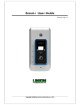
iPonic 624 QuickStart Guide
3. Installing the Equipment
1. Verifying the Contents
- Uncoil the 16 ft of sensor cables
- Attach the plugs into the designated ports
- Make sure to match the correct plug with the correct
sensor plugin labels room 1 or room 2
- Screw into the blue plugs securely
- Plug in the controller’s power cord into the outlet
When you open the box check to make sure it
contains the following:
1. An iPonic™ 624 controller
2. Two Sensors
3. User Manual
4. Quickstart guide
POWER UP YOUR iPONIC™
NOTE: There is a fine line on the surface of the iPonic Controller
window extending from the wheel toward the center.
The iPonic™ 624 has eight 115 VAC electrical outlets.
The outputs default settings allow you to control
two separate rooms using four of the outputs for
Room 1 and also four for Room 2.
process and does not affect the integrity or performance of the
unit in any way.
4. Powering On & Startup Wizard
Plug the iPonic™ 624 power cord into a clean power outlet to reduce noise and
interference. Once powered up the iPonic™ 624 controller will initiate the Startup
Wizard.
Step 1 Set Time & Date
- Use Button No. 1 to change the hour
- Use the Navigation Wheel to highlight the hour
- Use Button No. 2 and No. 3 to change the minutes
- Use Button No. 4 to set up meridian indicator (AM/PM)
- Use Button No. 5 to set up cycle (12hour/24hour)
Press OK to confirm time settings
- Next you will be prompted to set the date
- Use Button No. 1 to change the month
- Use Navigation Wheel to highlight the month
- Continue the same way with the day and year
Press OK to confirm date settings
Once you have set up the time and date, the Startup Wizard will ask if you would like to sync your
controller clock to the Internet. Press Button No. 1 for Yes or Button No. 2 for No.
Step 2. Basic Equipment Settings
To configure your basic equipment settings follow the instructions below...
- The controller defaults to the most commonly used equiptment
- Use Button No. 3 to check or uncheck equiptment options
- Use Button No. 5 and No. 6 or the Navigation Wheel to highlight fields
- Use Button No. 7 and No. 8 to toggle between Room 1 and Room 2
- Press OK to confirm your settings and proceed to the next option
-You will be asked if you’re using a CO2 tank or generator for Room 1 and Room 2
- Press OK to confirm settings
- Complete the Startup Wizard
6. Connect to Internet
2. Mount Your iPonic™ 624
Your iPonic™ 624 controller comes preset to connect to the internet. Preinstalled within your iPonic™ 624 is
a communication module. With a standard CAT 5 cable you can connect to the internet through your router
plug on the back side of the controller.
- Mount the controller at eyelevel and away from any
moisture or electrical sources
- Locate the 4 mounting holes at the base of the controller.
- At least 10 inches of workspace below the unit
- Mount controller to a sturdy surface
- If possible mount the controller outside and between the
two rooms
Note: The Ethernet port for the internet is inside
the iPonic™ 624. Perform the following steps to
connect to your controller:
Now plug in both Digital Intergrated Sensor Modules (DISM)
that are enclosed in the controller unit. For the best readings
hang the sensors plant level, but slightly out to the side
- Power down your controller
- Open up the hinged doors
- Route cable through opening at the base
- Locate Ethernet cable
- Plug in the cable the the ethernet port
- Plug in the other end to your router
- Close and lock the iPonic 624
Once you power up your iPonic™ 624 will automatically connect to the internet and link up to the Link4 Cloud Server
(iponic.link4cloud.com). A registartion key will be created for you. To access this key follow the instructions below:
to avoid direct light interference.
- From the Main Menu use the Navigation Button to highlight System Setup
- Then use the Navigation button to highlight Communication Setup
- Next Navigate to the Server Setup option, here you can view your Serial Number and Registration Key
.
equipment refer to the User Manual.
Your iPonic™ 624 Screen
1
5
2
6
3
7
4
8
When looking at the screen you will notice a difference
in light and dark. Room 1 settings are on a dark background and Room 2 is on a dark background. This helps
the user too differentiate between the two. The tabs of
the same light or dark shade correspond to the rooms
color that they match.
Visit our YouTube channel by
searching Link4 Corp
7. Congratulations!
Your iPonic™ 624 Controller has been set up and is
ready to grow immediately!
624
refer to the User Manual.
The total amperage of the equipment connected
to the iPonic™ 624 must not exceed 15 amps.
Delivering Confidence Through
Intelligent Environmental Controls
and Automation Solutions
22725 La Palma Ave., Yorba Linda CA 92887
866.755.5465
[email protected]
iponic.link4corp.com