1
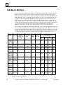
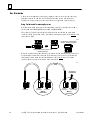
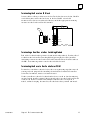
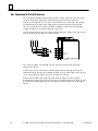
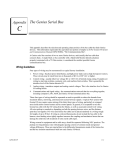
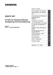
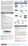
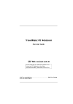
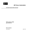
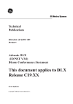
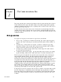
Chapter
2
2 The Communications Bus
section level 1 1
figure bi level 1
table_big level 1
This chapter describes the selection and installation of the bus cable that links Genius devices.
It also explains how fiber optics cable and modems can be utilized in applications requiring
immunity to higher levels of interference or lightning strikes, freedom from ground loops, or
greater distance between devices.
A communications bus consists of two or more Genius devices, and (usually) the serial bus
cable that connects them. A single block or bus controller with a Hand-held Monitor directly
attached, properly terminated with a 75Ω resistor, are considered the smallest possible Genius
communications bus.
Wiring Guidelines
Four types of wiring may be encountered in a typical factory installation:
1. Power wiring – the plant power distribution, and high power loads such as high horsepower motors. These circuits may be rated from tens to thousands of KVA at 220 VAC or
higher.
2. Control wiring – usually either low voltage DC or 120 VAC of limited energy rating.
Examples are wiring to start/stop switches, contactor coils, and machine limit switches.
This is generally the interface level of the Genius discrete I/O.
3. Analog wiring – transducer outputs and analog control voltages. This is the interface
level to Genius I/O analog blocks.
4. Communications and signal wiring – the communications network that ties everything
together, including computer LANs, MAP, and Genius I/O and communications bus.
These four types of wiring should be separated as much as possible to reduce the hazards
from insulation failure, miswiring, and interaction (noise) between signals. A typical PLC
system with Genius I/O may require some mixing of the latter three types of wiring,
particularly in cramped areas inside motor control centers and on control panels. In general, it
is acceptable to mix the communications bus cable with the I/O wiring from the blocks, as
well as associated control level wiring. All noise pickup is cumulative, depending on both the
spacing between wires, and the distance span they run together. I/O wires and
communications bus cable can be placed randomly in a wiring trough for lengths of up to 50
feet. If wiring is cord-tied (harnessed), do not include the bus cable in the harness, since
binding wires tightly together increases the coupling and mechanical stress that can damage
the relatively soft insulation of some serial cable types like 9182.
Wiring which is external to equipment, and in cable trays, should be separated following NEC
practices. The pickup over long-distance runs with adequate spacing consists of common
mode and ground voltage differences. These are rejected due to the differential transmission
mode of the communications bus and the bus isolation transformers built into each Genius
I/Oblock.
GEK-90486F-1
2-1
2
Selecting a Cable Type
The Genius bus is a shielded twisted-pair wire, daisy-chained from block to block and terminated at both ends. Proper cable selection is critical to successful operation of the system.
Each bus in the system can be any cable type listed in the table below. The 89182, 89207, 4794,
89696, and 89855 types are high temperature cables for use in severe environments, and are
qualified for use in air plenums. The 9815 type is water resistant, and can be used where
direct burial is required. Similar cables of equivalent terminating resistance such as 9207,
89207, and 9815 can be mixed. Do not mix cables of different impedance, regardless of cable
run length. The maximum run for mixed cable type equals the shortest length recommended
for any of the types used. Other, small-size twisted pair shielded wire of unspecified
impedance can be used for short runs of 50 feet or less, using 75 ohm terminations.
The excellent noise reduction of these cable types, and of the Genius communications system,
allow the communications bus to be mixed with other signalling systems and 120 volt AC control circuits without needing added shielding or conduits. Conservative wiring practices, and
national and local codes, require physical separation between control circuits and power distribution or motor power. Refer to sections 430 and 725 of the National Electric Code.
Cable #
& Make
(A)9823
(B)9182
(C)4596
(M)M39240
(B)89182
(B)9841
(M)M3993
(A)9818C
(B)9207
(M)M4270
(A)9109
(B)89207
(C)4798
(M)M44270
(A)9818D
(B)9815
(A)9818
(B)9855
(M)M4230
(A)9110
(B)89696
(B)89855
(M)M64230
(A)9814C)
(B)9463
(M)M4154
(A)5902C
(B)9302
(M)M17002
Maximum Length Cable Run,
Outer Terminating Numberof Dielectric Ambient
feet/meters at baud rate
Diameter Resistor* Conductors/ Voltage Temp
–10%to+20%
AWG
Rating Rating
153.6s 153.6e 76.8 38.4 D
1/2 Watt
.350in
8.89mm
150 ohms
2 / #22
30v
60C
2000ft
606m
3500ft
1061m
4500ft
1364m
7500ft
2283m
.322in
8.18mm
.270in
6.86mm
.330in
8.38mm
150 ohms
2 / #22
150v
200C
*120 ohms
2 / #24
30v
80C
100 ohms
2 / #20
300v
80C
2000ft
606m
1000ft
303m
1500ft
455m
3500ft
1061m
1500ft
455m
2500ft
758m
4500ft
1364m
2500ft
758m
3500ft
1061m
7500ft
2283m
3500ft
1061m
6000ft
1818m
.282in
7.16mm
100 ohms
2 / #20
150v
200C
1500ft
455m
2500ft
758m
3500ft
1061m
6000ft
1818m
.330in
8.38mm
.315in
8.00mm
100 ohms
2 / #20
100 ohms
4 (two pair)
#22
150v
60C
1500ft
455m
1200ft
364m
2500ft
758m
1700ft
516m
3500ft
1061m
3000ft
909m
6000ft
1818m
4500ft
1364m
.274in
6.96mm
100 ohms
4 (two pair)
#22
150v
200C
1200ft
364m
1700ft
516m
3000ft
909m
4500ft
1364m
.243in
6.17mm
75 ohms
2 / #20
150v
60C
800ft
242m
1500ft
455m
2500ft
758m
3500ft
1061m
.244in
6.20mm
75 ohms
4 (two pair)
#22
300v
80C
200ft
60m
500ft
152m
1200ft
333m
2500ft
758m
Notes: A = Alpha, B = Belden, C = Consolidated, M = Manhattan
D = Limited to 16 taps at 38.4 Kbaud
2-2
Geniust I/O System and Communications User’s Manual – November 1994
GEK-90486F-1
2
Using Other Cable Types
The cable types listed in the preceding table are recommended for use. If the cable types
listed above are not available, the cable selected must meet the following guidelines.
1. High quality construction. Most important is uniformity of cross section along the
length of the cable. Poor quality cable may cause signal distortion, and increase the
possibility of damage during installation.
2. Precision-twisted shielded wire of EIA RS422 standard type, having a uniform
number of twists per unit of length. In a catalog, this type of cable may also be listed
as twinaxial cable, data cable, or computer cable.
3. Relatively high characteristic impedance; 100 to 150 ohms is best; 75 ohms is the
minimum recommended.
4. Low capacitance between wires, typically less than 20pF/foot (60pF/meter). This
may be accomplished by inner dielectrics of foamed type, usually polypropylene or
polyethylene, having a low dielectric constant. Alternatively, the conductors may be
spaced relatively far apart. Lower impedance types have smaller cross–sections, and
provide easier wiring for shorter total transmission distances.
5. Shield coverage of 95% or more. Solid foil with an overlapped folded seam and drain
wire is best. Braided copper is less desirable; spiral wound foil is least desirable.
6. An outer jacket that provides appropriate protection, such as water, oil, or chemical
resistance. While PVC materials can be used in many installations, Teflon,
polyethelene, or polypropylene are usually more durable.
7. Electrical characteristics: cable manufacturers’ information about pulse rise time and
NRZ data rate is useful for comparing cable types. The Genius bit consists of three
AC pulses; the equivalent NRZ bit rate is about three times as great.
For assistance in selecting a specific cable type, please consult your local GE Fanuc application
engineer.
Prefabricated Cables
For applications using 150 ohm cables such as Belden 9182, prefabricated cables are
available in 15” (IC660BLC001) and 36” (IC660BLC003) lengths. These cables terminate
in mating connectors that simplify wiring between I/O blocks. The 36” cable is
recommended for Field Control installations.
SER 2
SER 1
SHD IN
SHD OUT
SHD SHD SER SER
OUT IN
2
1
GEK-90486F-1
Chapter 2 The Communications Bus
2-3
2
Bus Length
The maximum bus length for shielded, twisted-pair cable is 7500 feet. Some cable types
are restricted to shorter bus lengths. For example, for buses with a total cable length of
100 feet to 2000 feet Belden 9182 or Alpha 9823 or Belden 89182 can be used. In turn, the
bus length determines which baud rate may be selected.
If the application requires greater bus length, fiber optics cable and modems can be used,
as explained later in this chapter.
Bus Length and Baud Rate for Busses with Phase A Devices
If a bus has any Phase A Genius products (catalog numbers IC660CBDnnn, IC660CBSnnn,
IC660CBAnnn, IC660HHM500, or IC660CBB900/901), the bus must use 153.6 Kbaud
“standard” and the maximum bus length is 2000 feet. Therefore, only the cable lengths listed
under “153.6s” are permitted (“153.6e” refers to 153.6 Kbaud extended, which is not
compatible with 153.6 Kbaud standard).
Baud Rate Selection
A Genius I/O or communications bus can operate at one of four baud rates:
153.6 Kbaud standard, 153.6 Kbaud extended, 76.8 Kbaud, or 38.4 Kbaud.
Follow these guidelines when selecting the baud rate for a bus:
1. All devices on a bus must operate at the same baud rate (other busses in the system
may operate at different baud rates).
2. If there are any older Genius products on the bus (catalog numbers IC660CBDnnn,
IC660CBSnnn, IC660CBAnnn, IC660HHM500, or IC660CBB900/901), the bus must
be set up to use 153.6 Kbaud standard.
3. If the cable length is between 4500 and 7500 feet, you must select 38.4 Kbaud. This
data rate only supports a maximum of 16 device on the bus.
4. If the cable length is between 3500 and 4500 feet, select 76.8 Kbaud.
5. If cable length is between 2000 and 3500 feet, select 153.6 Kbaud extended.
6. If the cable length is less than 2000 feet, either 153.6 Kbaud standard or 153.6 Kbaud
extended can be used. The products are set to operate at 153.6 Kbaud standard
when shipped from the factory. The use of 153.6 Kbaud extended is recommended,
especially if the system will include a dual bus with Bus Switching Modules.
In noisy environments, 153.6 Kbaud extended provides improved noise immunity with
little effect on bus scan time. If a system is experiencing excessive blinking of the bus
controller’s COMM OK light, or if the I/O blocks’ I/O Enabled LEDs go off frequently,
153.6 Kbaud extended should be used.
The baud rate selected should be indicated on all blocks, especially if different busses in the
facility use different baud rates. Before connecting a Hand-held Monitor to a functioning bus,
check that it has been configured to the correct baud rate. If not, change the HHM baud rate
selection, turn off the HHM, connect it to the bus, then turn the HHM on.
2-4
Geniust I/O System and Communications User’s Manual – November 1994
GEK-90486F-1
2
Connecting Devices to the Bus
Devices can be placed in any physical sequence on the bus, however, communications
will be most efficient if devices are placed in the same sequence as their Device Numbers
(Block Numbers).
Each device has four terminals for the serial bus cable (Serial 1, Serial 2, Shield In, and
Shield Out). Connect the Serial 1 terminal of each block to the Serial 1 terminals of the
previous device and the next device. Connect the Serial 2 terminal of each block to the
Serial 2 terminals of the previous device and the next device.
Shield In of each block must be connected to Shield Out of the preceding device. For the
first device on the bus, Shield In can be left unconnected. For the last device on the bus,
Shield Out can be left unconnected.
When making bus connections, the maximum exposed length of bare wires should be
two inches. For added protection, each shield drain wire should be insulated with
spaghetti tubing to prevent the Shield In and Shield Out wires from touching each other.
Start
of Bus
End
of Bus
Terminating
Resistor
Terminating
Resistor
Serial 1
Serial 2
Shield In
Shield Out
Serial 1
Serial 2
Shield In
Shield Out
Because of reflections caused by the high speed of the bus, taps from a single bus should
not be made. Neither “T” nor “star” configurations, as shown below, are supported.
“T” Configuration
“STAR” Configuration
Exceptions to the “T” restriction are dual bus redundant systems, where short stubs are
permitted with Bus Switching Modules (Chapter 8), and fiber optic links, where fiber forms
the trunk line, and fiber optic modems link the fiber trunk line to Genius wire bus branches.
GEK-90486F-1
Chapter 2 The Communications Bus
2-5
2
Bus Termination
A bus must be terminated at each end by impedance that is correct for that cable type.
Impedance will be 75, 100, 120, or 150 ohms. The method used to terminate a bus
depends on the type of device at the end of the bus, as explained on the next page.
Using Prefabricated Terminating Resistors
Prefabricated molded connectors with terminating resistors are available for 75 ohms
(catalog number IC660BLM508) and 150 ohms (IC660BLM506).
They can be used with conventional bus cable and with the cables with pre-molded
connectors. With pre-molded cables., attach the prefabricated resistor to the female cable
end as shown below.
46493
Underside of prefabricated
resistor, showing projection
Slide prefabricated resistor onto
female cable end
Where two prefabricated cable ends meet, join the male and female ends (see below). If
a prefabricated cable will be at the end of the bus and you want to use a prefabricated
terminating resistor, make the cable installation so that a female connector will be
located at the device where the cable will be terminated.
464
Connect to
Last Device
male
connector
2-6
female
male
connector
connector
Mating
connectors
female
terminating reconnector
sistor (male)
Mating
connectors
Geniust I/O System and Communications User’s Manual – November 1994
GEK-90486F-1
2
Terminating the Bus at an I/O Block
Connect the bus cable to each device on the bus. For the first device on the bus, Shield In
can be left unconnected. For the last device on the bus, Shield Out can be left
unconnected. For devices on either end of the bus, install the appropriate terminating
resistor across the Serial 1 and Serial 2 terminals.
'
S1
S2
SHLD IN
SHLD OUT
Terminating a Dual Bus at a Bus Switching Module
Each cable of a redundant bus pair must be terminated independently. If either cable of
a redundant bus ends at a Bus Switching Module (ignoring any bus stubs), install its
terminating resistor across the Serial 1 and Serial 2 terminals where the cable attaches to
the BSM. No terminating resistor is used at the end of the bus stub.
Terminating the Bus at a Bus Controller or PCIM
For some bus controllers at the end of a bus, the correct terminating impedance must be
set using on-board jumpers before installing the module. The Series 90-70 Genius Bus
Controller, if terminated, must use an external resistor.
If a bus controller is at the end of a redundant bus, do not set the on-board terminating
resistors. Instead, install a resistor of the appropriate value across the Serial 1 and Serial 2
connectors on the Bus Controller. This technique enables boards to be replaced, if
needed, without disrupting the entire bus, since the busses always remain terminated.
GEK-90486F-1
Chapter 2 The Communications Bus
2-7
2
Bus Connection for Critical Processes
The recommended method of connecting the bus to an I/O block is to wire it directly to
the block’s Terminal Assembly. Such bus connections are normally considered
permanent. They should never be removed while the bus is in operation; the resulting
unreliable data on the bus could cause hazardous control conditions. If the possible
removal or replacement of a block’s Terminal Assembly would result in breaking the
continuity of the bus, the bus should first be turned off.
If the bus controls critical processes that cannot be shut down, blocks can be wired to the
bus via an intermediate connector, as shown below.
I
N
O
U
T
S1
S2
SHLD IN
SHLD OUT
'
S1
S2
SHLD IN
SHLD OUT
The connector shown is #A107204NL from Control Design, 458 Crompton Street,
Charlotte NC, 28134.
Alternatively, the wire ends can be soldered together before inserting them into the
terminals. When removing the Terminal Assembly, cover the ends of the wires with tape
to prevent shorting the signal wires to one another or to ground.
Both of these methods allow the block’s Terminal Assembly to be removed while
maintaining data integrity on the bus. If blocks are connected to the bus in this way, field
wiring to the blocks should also provide a means of disconnecting power to individual
blocks.
2-8
Geniust I/O System and Communications User’s Manual – November 1994
GEK-90486F-1
2
Bus Ambient Electrical Information
Most capacitively- and magnetically-coupled noise shows up as common mode voltage
on the bus. The bus provides a 60 dB common mode rejection ratio. A noise spike above
1000 volts would be required to corrupt the data. The bus receivers filter out corrupted
data and perform a 6-bit cyclic redundancy check to reject bad data. Corrupted signals
due to noise show up as missed data rather than incorrect data. The bus continues
operating to the maximum extent possible when bus errors are detected; random bus
errors do not shut down communications. Bad data is rejected by the receiving device
and excessive errors are reported to the controller. Bus errors are indicated by flickering
of I/O block and bus controller LEDs. If excessive bus errors occur, the problem should be
found and corrected.
Lightning Transient Suppression
Running the bus cable outdoors or between buildings may subject it to lightning
transients beyond the 1,500 volt transient rating of the system. Installing cable
underground reduces the probability of a direct lightning strike. However, buried cables
can pick up hundreds of amperes of current when lightning contacts the ground nearby.
Therefore, it is important to protect the installation by including surge protectors on
underground data lines. The cable shields should be grounded directly. Surge
suppressors and spark gaps should be used to limit the voltage that might appear on the
signal lines. It is recommended to install two (only) silicon surge suppressors or spark
gaps to control transients of 1 to 25 Kilovolts from 100 to 1000 amps or more. These
devices should be installed close to the entrance of the bus to the outdoors.
Silicon Surge Suppressors are available many sources, including Clare/General
Instruments, Motorola, and Ledex/Lucas. Ledex type DFPO27 is one such device. For
information about this product, in the US contact Lucas Industries Incorporated, 5500
New King Street, Troy, Michigan 48098 (tel: 313 879-1920, fax: 313 552-1020). Spark gaps
are available from Clare. Refer to the vendor’s literature for installation details.
In extreme situations, such as totally-isolated power systems, additional protection
against lightning damage should be provided by adding surge suppressors for groups of
I/O blocks. Such suppressors should be installed from incoming power leads to ground
(enclosure baseplate/block case where leads enter the enclosure).
Alternatively, fiber optics cable and modems, described on the next page, can be used to
provide immunity against lightning-induced transients.
Using a Dual Bus
For applications where communications between the controller and I/O blocks must be
maintained even if a cable break should occur, a dual bus can be used. (Genius I/O blocks
are interfaced to such a dual bus via one or more Bus Switching Modules). Each bus
cable of the pair requires its own bus controller.
A dual bus can provide the same types of functions as a single bus. If cable breaks are not
a problem, or if it is not necessary to maintain communications if a break should occur,
dual cables are not needed. Chapter 8 describes the use of dual busses and bus
controllers for different types of CPU.
Belden 9855 and 9302 are 4-conductor cables, and can be used for dual busses. Identify
the separate twisted pairs on these types, and do not use extra pairs for any other
purpose.
GEK-90486F-1
Chapter 2 The Communications Bus
2-9
2
Using Fiber Optics
If the installation requires immunity to higher levels of interference or lightning strikes,
freedom from ground loops, or greater distance between devices, fiber optics cable can
be used. GE Fanuc does not supply fiber optics products directly. The products described
on the following pages have been used successfully with GE Fanuc systems.
Pheonix Digital
Pheonix Digital, 7650 East Evans Rd. Bldg. A, Scottsdale, AZ 85260 (phone 602 483-7393
or FAX 602 483-7391) provides a full line of fiber optic communication products and
services. They can provide modems that install directly in a Series 90-70 PLC as well as
stand-alone modems in rackmount/panelmount industrial enclosures with integral
power supplies. Fiber optic cables are available for industrial, aerial, direct burial, riser
and plenum installations. Pheonix Digital also supplies modems for SNP applications, for
controller/programmercommunications.
Product features include:
H Online error checking
H Fault prediction, fault location, fault tolerance
H Redundant fiber media
H Distances from 6 feet (1.8 Meters) to 6 miles (9.6 Km)
H Selectable wavelengths: 850 nanometers, 1300 nanometers
The following example shows three Series 90-70 PLCs connected to both Genius and
SNP fiber optic busses using rack-mounted and stand-alone modems. Genius Bus
Controllers and I/O blocks can be cabled directly to modems using standard twisted pair
wire. PLCs and programmer computers can be cabled directly to modems using Pheonix
Digital’s interconnection cables.
Genius Bus
SNP Bus
Modem
Fiber Optic
SNP Bus
Fiber Optic
Genius Bus
Bus Controller
CPU
Modem
Modem
2-10
Modem
Modem
Modem
ÍÍÍÍÍÍÍÍ
Í
ÍÍÍÍÍÍ
ÍÍÍ
Í
Í
ÍÍÍÍÍÍÍÍ
ÍÍÍ
ÍÍÍ
ÍÍÍÍ
ÍÍ
ÍÍÍÍ
Í
Í
ÍÍÍ
Í
Í
ÍÍÍ
ÍÍÍÍÍÍÍ
ÍÍ
Í
Í
Í
ÍÍÍÍÍÍ
ÍÍ
Geniust I/O System and Communications User’s Manual – November 1994
GEK-90486F-1
2
Specifications
Fiber optic cable type
Mating connector
Transmit launch power
Receive sensitivity
Environmental:
Operating temperature
Storage temperature
Relative humidity
Modem dimensions:
Series 90-70 plug-in
Stand-alone modem
GEK-90486F-1
Chapter 2 The Communications Bus
Multimode
SMA stype 906 (ST option available)
–15dbm
–32dbm
0C to 60C
–40C to 80C
0 to 95%, non-condensing
Standard Series 90-70 module
3.5” (8.89cm) H x 17.0” (43.18cm) W x 7.0” (17.78cm) D
2-11