1
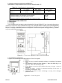
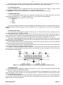
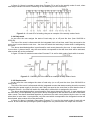
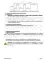
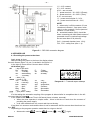
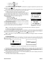
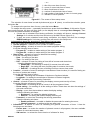
«NOVATEK-ELECTRO» Ltd Intellectual industrial electronics PROGRAMMABLE MULTIFUNCTIONAL TIMER REV – 303 OPERATIONAL MANUAL SPECIFICATION www.novatek-electro.com ~2~ ATTENTION! Before using the Unit, please, carefully read the Operational Manual. Before connecting the Unit to power supply, please, keep it for two hours period under the operational conditions. Do not use the corrosive materials or organic compounds (spirits, gasoline, solvents etc.) for cleaning the device. IT IS FORBIDDEN TO OPEN AND REPAIR THE UNIT AT OWN DISCRETION. The device components can be under live electricity. IT IS FORBIDDEN TO USE THE DEVICE WHICH HAS THE MECHANICAL DAMAGES. IT IS NOT ALLOWED TO LET THE WATER INSIDE THE DEVICE AND TO USE THE DEVICE IN CONDITIONS OF HIGH HUMIDITY. ATTENTION! THE DEVICE IS NOT INTENDED TO BE USED FOR LOAD COMMUTATION AT SHORT CIRCUIT. THEREFORE THE DEVICE MUST BE USED IN POWER LINE PROTECTED BY AUTOMATIC CIRCUIT BREAKER (FUSE) WITH ALARM VOLTAGE NOT MORE THAN 16 А OF CLASS В. The devise is accident-free provided the operational rules are observed. INTRODUCTION This operational manual is issued for description of the device, operational modes, design, procedure of operation and technical maintenance of Programmable Multifunctional Timer REV-303 (further in the text «timer», «REV-303» or «timer REV-303»). Terms and abbreviations: Display – a graphic display 128х64 dots; Default settings – preset parameters values used by the timer until the user explicitly changes these values; SR – Sun Rise; SS – Sun Set; RAM – Random Access Memory. 1 SCOPE OF USE Timer REV-303 is a microprocessor-based programmable device designed to control the loads in real time without permanent maintenance with minimal expenses and maximal electricity saving. Timer REV-303 can be used to switch on the heating system, pumps, fans, school signals, street illumination, highlighting of buildings fronts (around territories, car parking and other objects). Timer REV-303 can automatically define the time of sun rise and sun set on the basis of entered coordinates and current time which enables to control the illumination without using the external sensors. Timer REV-303 features: Two programs of control with quick switching over between them; Four operational modes of timer (astronomic, weekly, daily and simple modes); Calendar with operational life for 6 years period without external power supply; Accuracy of planned events 1 second and 0.1 second in simple mode of timer; Total internal memory for 500 independent events, divided between the programs; Automatic shift for summer time and winter time; Light-emitting graphic display; Indication of current state of relays contacts; Control of timer with 4 buttons, located on the front panel; Possibility to set an access pass code for a setup menu; Power supply from the electric line 24 - 265 V 50/60 Hz or from a direct-current source of 8-24 V. REV-303 NOVATEK-ELECTRO ~3~ 2 SPECIFICATION AND OPERATIONAL CONDITIONS 2.1 Main technical characteristics The main technical characteristics of REV-303 are resulted in table 2.1. Table 2.1 – Main technical characteristics Item External power supply ( / ), V Power line frequency, Hz Rower consumption (from power line ~230 V), W, not more Power supply from DC supply source ( ), V Rower consumption (from DC supply source +12 V), W, not more Accuracy of planned events, sec Max. number of planned events Work period of clock without power line supply (at temperature 25 ºС), years Accuracy of clock, at temperature 25 ºС, not more, sec/day Min. time of contacts commutation, sec Indication of load relay state Parameters saving at power supply loss Data saving period, years, not less Number and type of contacts, 16 A Weight, kg, not more Overall dimensions, mm Intended use of device Value 24 – 265 45 – 65 1.5 8 – 24 0.6 1 и 0.1* 500 6 1 0.015 yes yes 10 1 toggle type 0.2 100 х 36 х 67 Control and distribution devices continuous ІР40 / IP20 II UHL3.1 II II 450 2.5 0.2 – 2.5 0.4 Standard operational mode Device protection class (front panel / terminals plate) Electric shock protection class Climatic type Допустимая степень загрязнения Overvoltage category Nominal isolation voltage, V Nominal withstand impulse voltage, kV Cross section of terminals connection wires, mm² Terminal screws, N*m Installation on standard fixing DIN-rail 35 mm Position in space user-defined -----* Accuracy of planned events 0.1 sec. is available only for timer work simple mode; Timer REV-303 complies with requirements of: Complex low voltage distribution devices. Part 1. General rules (IEC 60947-1:2004, ІDТ). Low voltage switch and controller. Part 6-2. Multifunctional equipment. Control and protection switch devices (ІEC 60947-6-2:1992, ІDT). Electromagnetic compatibility. Radio frequency industrial, scientific equipment. Electromagnetic devices specification. Standards and methods of measuring (CISPR 11:2004, IDT). Electromagnetic compatibility. Part 4-2 Testing and measuring methods. ESD resistance testing (IEC 61000-4-2:2001, IDT). The harmful matters in unallowable content are not present. 2.2 Operational conditions Timer REV-303 is designed for operation in the following conditions: Ambient temperature from - 30 to +55 ºС; Atmosphere pressure from 84 to 106.7 kPa; Relevant air humidity (at temperature +25 ºС) 30 … 80%. Timer REV-303 is not designed for operation in conditions of vibration and impacts. NOVATEK-ELECTRO REV-303 ~4~ 2.3 Output contacts specification of REV-303 Specification of output contacts of REV-303 is resulted in table 2.2 Table 2.2 – Specification of output contacts Max. voltage at Max. power U~ = 250 V cosφ = 0.4 4А 1000 VA cosφ = 1 16 А 4000 VA Commutation durability of contacts - mechanical service durability, times - electric durability 16 А 250 V АС, times, not less - electric durability 4 А 24 V DC, times, not less - electric durability 4 А 250 V АС (cosφ = 0.4), times, not less Max. voltage at Udir = 24 N 4А 10 000 000 100 000 60 000 100 000 3 DESCRIPTION AND OPERATION 3.1 Description 3.1.1 Design Timer is designed in the plastic casing intended for fixing on DIN-rail 35 mm, the casing dimensions (100 mm х 36 mm х 67 mm) 2 modules of S type. The casing is made of impact proof, self-extinguishing plastic. The casing visual appearance and overall and fixing dimensions are resulted in fig. 3.1. There is an option of casing modification with semi-transparent cover and front panel sealing possibility (available only under additional agreement). Figure 3.1 – Timer visual appearance and overall dimensions 3.1.2 Indication and control In figure 3.2 is shown the visual appearance of timer front panel. 1 – Display; 2 – Button ▲ (up), is used for upward scrolling or increasing of parameter value; 3 – LED indicator of load relay state (lights on – when the load relay is on, lights off – when the load relay is off); 4 – Button Menu, is used to enter (escape) the menu of setup or reset of parameter; 5 – Button ▼ (down), is used for downward scrolling of the menu or decreasing of parameter value; 6 – Button Ок, is used for action confirming or saving of the changed parameter value. Figure 3.2 – Timer front panel REV-303 NOVATEK-ELECTRO ~5~ All settings of the timer are made with the help of the buttons. The current time and timer state are shown on the display, and the state of load relay is shown with the help of LED indicator. 3.1.3 Real time clock Timer is equipped with an integrated real time clock with internal power supply (in case of main power supply loss) from reserve power source – a lithium battery element. Attention – Prior the use of the timer it is necessary to set the exact date and time. 3.2 Operational mode 3.2.1 The operational mode of the timer is based on switching on/off of load relay under one of the user-defined programs Pх (х – Program number from 1 to 2), which are set separately. Each program Px can be set to one of the modes: Astronom; Week; Daily; Simple. For each operational mode the user can assign the independent events. In the timer there can be assigned maximum 500 events which can be distributed for all programs (P1 and P2) and operational modes. 3.2.2 Astronom mode As an event the user assigns the state of load relay (on or off) and a shift of time in reference to the sunrise and sunset (from -23:59 to +23:59). Every day the timer calculates the real time of sunrise and sunset, sums this time with the time of event, and then the resulted time is referenced with the clock of real time and if the resulted time is more or equal to real time – the time will switch the load relay in state which is assigned by the event. The above described algorithm is performed for each event planned by the user. In case when there are more than 1 event planned, only the event which corresponds to the real time clock will be activated, other events will not be performed. At the latitudes where there is a polar day, the events concerning the sunset will not be performed and the time of the sunrise is taken as equal to 00:00. At the latitudes where there is a polar night the events concerning the sunrise will not be performed, and the time of the sunset is taken as equal to 00:00. In figure 3.3 there is resulted a case of Program P1 being set for the astronomic mode of work with four events for a street illumination during 4 hours at sunset and 4 hours at sunrise, the rest of the time the illumination is switched off. figure 3.3 – Street illumination as an example of astronomic mode of work 3.2.3 Week mode As an event the user assigns the state of load relay (on or off), a day of the week (since Mo through Fr) and the time (from 00:00:00 to 23:59:59). The day of the week and time of the event are referenced with the integrated clock of real time, and if they are equal or the event time is more than the real time – the time will switch the load relay in state which is assigned by the event. The above described algorithm is performed for each event planned by the user. In case when there is more than 1 planned event, only the event which corresponds to the real time clock will be activated, other events will not be performed. NOVATEK-ELECTRO REV-303 ~6~ In figure 3.4 there is resulted a case when Program P1 is set for the weekly mode of work, when each day at certain time there is switching on and switching off of the load relay. Figure 3.4 – On and Off of a loading relay as an example of the weekly mode of work 3.2.4 Daily mode As an event the user assigns the state of load relay (on or off) and the time (from 00:00:00 to 23:59:59). The time of the event is referenced with the integrated clock of real time, and if they are equal or the event time is more than the real time – the time will switch the load relay in state which is assigned by the event. The above described algorithm is performed for each event planned by the user. In case when there is more than 1 planned event, only the event which corresponds to the real time clock will be activated, other events will not be performed. In figure 3.5 there is resulted a case when Program P1 is set for daily mode of work with six events. Figure 3.5 – Switching on of the load as an example of daily mode of work 3.2.5 Simple mode As an event the user assigns the state of load relay (on or off) and the time (from 00:00:00:0 to 23:59:59:9). The time of the event is referenced with the integrated counter that starts counting since the moment of providing the power supply to the timer, and if they are equal or the event time is more than the time of integrated counter – the timer will switch the load relay in state which is assigned by the event. The above described algorithm is performed for each event planned by the user. In case when there are more than 1 event planned, only the event which corresponds to the real time clock will be activated, other events The above described algorithm is performed for each event planned by the user. In case when there is more than 1 event planned, only the event which corresponds to the integrated counter will be activated, other events will not be performed. In figure 3.6 there is resulted a case when Program P1 is set for the simple mode of work with six events. In this mode after providing the power supply there is a performance of a simple list of events. REV-303 NOVATEK-ELECTRO ~7~ Figure 3.6 – Switching on of the loading as an example of simple mode of work 4 TECHNICAL MAINTENANCE AND SAFETY RULES 4.1 Safety rules 4.1.1 THERE IS A HAZARDOUS VOLTAGE IN REV-303. WHILE REPAIRING, TECHNICAL MAINTENANCE, INSTALLATION WORKS IT IS NECESSARY TO DISCONNECT REV-303 AND ITS ELEMENTS FROM THE POWER SUPPLY. 4.1.2 It is not allowed to use REV-303 in corrosive environment with acids, alkyls, oils etc. in the air. 4.1.3 Installation, setting and technical maintenance of the time must be carried out only by the authorized qualified personnel who has studied this operational manual. 4.1.4 At operation and technical maintenance it is necessary to observe the requirements of normative documents: “The rules of technical operation of electric devices” and “Safety rules of operation with electric devices”. 4.2 Procedure of technical maintenance The recommended periodicity of technical maintenance – every six months. The technical maintenance consists of visual examining during which there should be checked the connection of wires to the devise terminals and absence of damages and cracks on the case. If the after power is turned off the timer the real time clock is reset - must replace the internal battery. To replace the battery should contact the place of purchase or the manufacturer of the timer. During the technical maintenance it is necessary to observe all safety rules stated in item 4.1. 5 PREPARATION FOR OPERATION 5.1 General provisions Prepare the cables for connecting the timer with power supply and external units. To provide the reliability function of electric connections it is recommended to use the copper wires with clean connection ends. The stripping of the wires should be made in the way that the stripped ends of the wires after connection to the timer are not out of the connection terminals. The recommended cross section of the wires is 0.75 – 2.5 mm². 5.2 Connection The connection of REV-303 should be made according to the diagram resulted in the figure 5.1. At the connection of DC power supply (terminals 5, 6) the polarity observance is not necessary. ATTENTION: THE LOAD CONNECTION TERMINALS CAN WITHSTAND MAX. VOLTAGE OF 265 V. TO AVOID THE ISOLATION ELECTRIC FAULT IT IS FORBIDDEN TO MAKE CONNECTION TO POWER SUPPLY SOURCES WITH VOLTAGE HIGHER THAN THE SPECIFIED ONE. NOVATEK-ELECTRO REV-303 ~8~ 1,2 – N.O. contact; 2,3 – N.C. contact; 4,5,6 – are not used; 7 – power terminal ~ 24 ÷ 265 V (Phase); 8 – power terminal ~ 24 ÷ 265 V (Zero); 9,10 – are not used; 11 – power terminal plus 8 ÷ 24 V; 12 – power terminal minus 8 ÷ 24 V; NOTE 1 – when relay is off the contacts 2,3 are closed and contacts 1,2 are open, when relay is on the contacts 2,3 are open and contacts 1,2 are closed; 2 – automatic breaker (QA1) should be taken concerning the least rated current of protected circuit or nominal load voltage but not more than 20 А (class B). QA1 – Automatic breaker (max. 16 A); FU1, FU2 – safety fuse (max. 1 A) Figure 5.1 – REV-303 connection diagram 6 INTENDED USE 6.1 Providing the power to the timer Apply power to timer. After providing the power to the timer the display shows the main screen (figure 3.2, pos.1) resulted in the figure 6.1. In the right up corner there is current date in format dd dt mmm yyyy: dd - day of the week. Mo - Monday; Fr - Friday; Tu - Tuesday; Sa - Saturday; We - Wednesday; Su - Sunday. Th - Thursday; dt - date (1-31). mmm - month (1-12): Jan - January; Jul - July; Feb - February; Aug - August; Mar - March; Sep - September; Apr - April; Oct - October; May - May; Nov - November; Jun - June; Dec - December. yyyy - year (2000 - 2099). Рисунок 6.1 – Главный экран таймера If in the setting the automatic recycling of the program is allowed after its completion then in the left up corner there is a sign . In the middle there is Current Time in 24 format (hours, minutes, seconds): When the timer operates in simple mode – there is the time of work since the moment of providing the power supply. In all other modes there is a current real time on the day. If real time is in summer mode and the timer is set for automatic shift for summer time then there is a sign DST. Depending on the program operation mode there is a sign on the left: REV-303 Astronomic mode: – sunrise; – sunset; – day; – night; NOVATEK-ELECTRO ~9~ Weekly mode – clock; Daily mode – clock; Simple mode – seconds timer. When there is no planned event, program is switched off or program competed its cycle then on the left there is a sign – lock. At the bottom line there is a day indicator of events where numbers from 0 to 24 correspond the time of the day and the graphic sticks indicate the events at certain time. 6.2 Review the time of the next or previous event To review the time of the next or previous event is made by one-hold pushing of the button ▲ (up – next event) or ▼ (down – previous event). When there are the events in the timer the display will show the screen resulted in figure 6.2. On this screen: - load relay state (ON); - time of event (SS 19:43:47). - program number and work mode (P1 : Astronomic). When there are no events in the timer the display will shows the screen resulted in figure 6.3. For scrolling all the events it is necessary to push repeatedly the buttons ▲ (up) or ▼ (down). The screen with an event will be displayed for 10 seconds and then the timer will return to the main scream. Рисунок 6.2 – Time of event Рисунок 6.3 – No events Note – to review the events it is necessary to be on the main screen of the timer, a figure 6.1. 6.3 The forced change of a load relay state For the forced change of a load relay state it is necessary: on the main screen push and hold for 2 seconds the button ОK. At this action the relay will change its status to the opposite and the display in the left corner will show the pictogram (load relay is off) or (load relay is on). Note – when there is a new event the load relay automatically will change its status in accordance with event settings. 6.4 Timer setup menu To enter the timer setup menu it is necessary: in the main screen mode, press and hold the button Menu for 2 seconds. If there was a pass code setting, the timer will offer to enter the pass code (fig. 6.4 Pass code screen). Pass code screen Pass code error message Figure 6.4 – Pass code screen and pass code error message screen Procedure of pass code entering: by button Menu select the necessary digit of the pass code (the selected digit will be highlighted by cursor), by the buttons ▲ (up) or ▼(down) select digit from 0 to 9. After completion of the pass code selecting, push the button Ок, in case if the pass code is incorrect the display will show the message about pass code error as in figure 6.4. If the entered pass code is correct or if it was earlier disabled by the user the display will show the list of available items of the main menu. The menu of timer’s setup is resulted in the figure 6.5. NOVATEK-ELECTRO REV-303 ~ 10 ~ 1 – title of the core item of menu; 2 – cursor of current sub item of menu; 3 – titles of sub items of menu; 4 – number of selected sub item of menu; 5 – total number of sub items of menu in current group; 6 – indicator of cursor position. Figure 6.5 – The screen of timer setup menu The selection of menu items is made by buttons ▲ (up) or ▼ (down), to confirm the selection, press the button Ок. To escape to the previous item of menu, press the button Menu. To escape the setup menu – repeatedly several times press the button Menu. At this action if there were made changes, the timer will save them (on the display there is a message Save Changes). Then the timer will make verification of changes: If there are no mistakes found during verification, the display will show a message Correct Settings for 2 minutes and the timer will return to the Main Screen (figure 6.1); If there are some mistakes found during verification, the display will show the message ERROR settings for 2 minutes, and the timer will return in the setup menu. In Appendix А there is a structure of Timer Menu in a tree-type. In the list of upper level there are the following menu items: Current program – enables to set a number of master program; Program setting – a branch of menu for the master programs setting; It has the following items of menu: o Program P1 – enables to make setting of the master program 1; o Program P2 – enables to make setting of the master program 2. Date & Time – a branch of menu for date and time setting; It has the following items of menu: o Date – for setting of the date; o Time – for setting of the time; o DST – a branch of menu for setting of time shift of summer and winter time. It has the following items of menu: Enable DST – for switching on and off of summer time shift mode; Begin DST – for setting the term of shifting start for summer time mode; End DST – for setting the term of shifting end from summer time mode. Location – a branch of menu for setting the coordinates of timer location (it is used for finding out the time of sunrise and sunset). It has the following items of menu: o Latitude – for setting the coordinates of Northern or Southern latitude; o Longitude – for setting the coordinates of Western or Eastern longitude; o GMT – for setting the time zone by Greenwich. Control – a branch of menu for controlling the display, memory and security of timer; It has the following sub items of menu: o Reset event – for deleting all lists of events in all the programs of timer; o Reset setting – for resetting of all the settings of timer. Reset does not alter the settings of time and events lists; o Display – menu item that enables to make the display setting; It has the following sub items: Brightness – for setting the display brightness; Auto off – for setting the mode of display switching off. o Password – a menu item for setting the security parameters. It has the following sub items: Enable password – to enable or disable the pass code for entering the menu; Change password – to setting up the new pass code. Information – a branch of menu for reviewing the general information of timer. It has the following menu sub items: o Events state – to review the number of planned events in all programs, the max. available number of events and memory state; o SW version – to review the current version of software for timer; REV-303 NOVATEK-ELECTRO ~ 11 ~ o Device – to review the current state of RAM, device temperature and work time since the moment of device switching on. 6.5 Timer programs setup 6.5.1 General provisions For setting of one of the master programs Pх (х – number of master program from 1 to 2) it is necessary to make the following steps in menu: Menu→Program setting→Program Pх. Each program Pх has the following sub items of menu: Mode – for setting one of the following operational modes of program: o Astronom – mode of performing the astronomic list of events; o Week – mode of performing the weekly list of events; o Daily – mode of performing the daily list of events; o Simple – mode of performing the simple list of events. Advanced – it has the menu items for fine setting of program operation: o Auto restart – it shows whether the list of events of selected mode will be performed only once during the selected time or it will be repeated in cycles. Astronom event – a list of events for astronomic mode of program operation: Week event – a list of events for weekly mode of program operation; Daily event – a list of events for daily mode of program operation; Simple events – a list of events for simple mode of program operation. For changing the list of events it is necessary: being in one of the list of events, press the button Ок, the display of the timer will show the pop-up menu with the following items: Add – to add a new event; Delete – to delete a selected event; Delete all – to delete all events of current list. Selection of menu items is carried out by buttons ▲ (up) or ▼ (down), to confirm the selection, press the button Ок. To close the pop-up menu without selection, press the button Menu. 6.5.2 Adding an event to the list To add an event in the list it is necessary: being in the one of the list of events press the button Ок, the display will show the pop-up menu. By buttons ▲ (up) or ▼ (down) select the item Add, to confirm the selection press the button Ок. the display depending on the selected list of events will show: ON SR +00:00 – for astronomic list of events; ON Mo 00:00:00 – for weekly list of events; ON 00:00:00 – for daily list of events; ON 00:00:00:0 – for simple list of events. Where: ВКЛ – cursor for selecting the edited parameter; ON – a load relay status (ON or OFF); SR – the sun position (SR – sunrise or SS – sunset); Mo – day of the week (Mo, Tu, We, Th, Fr, Sa, Su); +00:00 – shift of event time in regard of time of sunrise or sunset (hours : minutes); 00:00:00 – time of event (hours : minutes : seconds); 00:00:00:0 – time of event (hours : minutes : seconds : hundreds of millisecond). Editing of selected parameter is made by the buttons ▲ (up) or ▼ (down). Selection of the next event is made by the button Menu. For saving the event, press the button Ок. The timer will add the new event to the list and display for 2 seconds will show the message Added, then the time will return to the list of events. 6.5.3 Deleting the event from the list For deleting the event from the list it is necessary: being in one of the lists of events, by buttons ▲ (up) or ▼ (down) select the event which is to be deleted and press the button Ок, the display will show the pop-up menu. By buttons ▲ (up) or ▼ (down) select the item Delete and confirm the selection by the button Ок. The timer will delete the selected and the display will for 2 minutes show the message Deleted, then the timer will return to the list of events. NOVATEK-ELECTRO REV-303 ~ 12 ~ 6.5.4 Deleting of all events from the list For deleting of all events from the list it is necessary: being in one of the lists of events, press the button Ок, the timer display will show a pop-up menu. By buttons ▲ (up) or ▼ (down) select the item Delete all and confirm the selection by pressing the button Ок. The timer will delete all the events from the current list and the display for 2 minutes will show the message Deleted, then the timer will return to the list of events. 6.6 Total reset of timer to the factory settings For total reset of the timer to the factory settings (including the pass code) it is necessary while holding the buttons ▲ (up) and ▼(down), provide the power to the timer. The timer will show on the display the service menu: Testing – a menu item for testing the timer; Reset all – a menu item for total reset of the timer; Exit – exit from the service menu. By buttons ▲ (up) or ▼(down) select the menu item Reset all and press the button ОK, the timer will perform the reset of the settings and events to the factory settings, the display will show a message Reset complete!. By buttons ▲ (up) or ▼(down) select the item Exit and press the button ОK, the timer will make the restart and return to the standard mode of work. 7 SERVICE LIFE AND MANUFACTURER'S GUARANTEE 7.1 The service life of REV-303 is 6 years. After the end of this period, please, contact the manufacturer. 7.2 The storing period is 3 years. 7.3 The operational guarantee period is 36 months since the date of sale. During the guarantee period the manufacturer makes the device repair free of charge provided the observance of technical requirements, provisions of storing, connecting and operation by the user. The device is not covered by the guarantee in the following cases: the expiration of guarantee or service life period; the device has the evidence of mechanical damages (cracks, cuts, deformations etc.), as a result of high or low temperatures, mechanical stresses, fractions, impacts etc.; the evidence of moisture influence, ingress of foreign matters, dust, dirt inside the device; repair is made by unauthorized person or organization; the completeness of device does not correspond “User’s Manual” (absence of gages, modification of electric circuit, changing of values of components); damage as a result of electricity or voltage values increasing the nominal ones, improper or careless use, not observing the instructions of installation and operation; lightning discharge, fire, flood, absence of ventilation and other reasons beyond the manufacturer’s control. 7.4 The guarantee and post guarantee service should be made in the region of purchase. 7.5 The manufacturer’s guarantee does not cover the direct and indirect losses, lost or damage, as well as expenses due to shipping of the device to a guarantee service center. 7.6 The post guarantee service (according to the current prices) is to be made by the manufacturer. 8 SHIPPING AND STORING REV-303 should be kept in the original packing in indoors premises with temperature from -45 up to +60 C and relative humidity not more than 80 % with absence of vapors in the air which are harmful for packing and details of the device. REV-303 NOVATEK-ELECTRO ~ 13 ~ Appendix А (recommended) Structure of timer REV-303 menu NOVATEK-ELECTRO REV-303