1
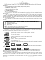
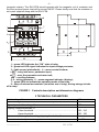
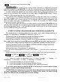
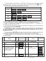
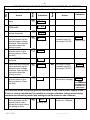
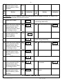
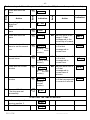
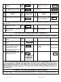
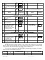
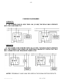
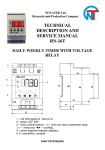
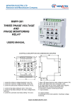
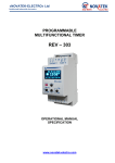
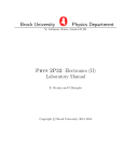
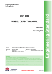
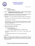
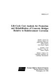
NOVATEK-ELECTRO LTD
Research-and-Manufacture Company
RN-16TM
LIGHT-SENSITIVE
MULTIFUNCTIONAL
DAILY-WEEKLY TIMER
SERVICE MANUAL
www.novatek-electro.com
-2-
1 APPLICATION
Multifunctional relay RN-16TM (hereinafter RN-16TM) performs the following
functions:
- Programmable real time switch (daily-weekly timer)
- MIN/MAX voltage relay
- Light-sensitive photo relay
- Voltage indicator
The RN-16TM is designed for:
- Turning ON/OFF the power load (equipment) according to the time schedule preset
by the user;
- Turn OFF home used or industrial single phase (240V / 50Hz) power load (equipment)
in case the unallowable voltage fluctuations are detected. When the voltage returns back to
normal parameters - the device will automatically turn ON the power load (equipment) with
the user defined time delay;
- Turn ON/OFF the power load according to the curtain illumination level that the user
may set
Relay works in 3 basic operation modes (I-III) and 2 mixed modes (IV-V):
I. Н – daily-weekly timer;
II. U – MIN/MAX voltage relay;
III. F – photo-relay;
IV. HU – daily-weekly timer with voltage control function;
V. FU – photo-relay with voltage control function.
Depending on the preset operation mode the LED display of the RN-16TM indicates
the following information (please see article “6” on Figure1).
I. Mode Н - current time in format : hours – blinking point - minutes
16.45
16 hours 45 minutes
II. Mode U - present voltage level correct to the nearest tenth
221.5
221.5 Volts
III. Mode F - letter F - space – illumination level
F 35
illumination level 35
IV. Mode HU - time and voltage values are shown one after another divided by dashed
line
16.45
----
221.5
----
V. Mode FU - illumination level and voltage level are shown one after another divided
by dashed line
F 35
----
221.5
----
The User may create 2 different independent sets of parameters SP1, SP2 and may
delete any of these sets if necessary. Thus the client may save in the device memory 2
different settings for curtain cases.
Output terminals of the RN-16TM may commutate the power load up to 3,5 kW (16A). If
total power load connected to the RN-16TM is more than 3,5 kW (16A) then it will be
necessary to commutate the required power load with a use of appropriate contactor
RN-16TМ
NOVATEK-ELECTRO
-3-
(magnetic starter). The RN-16TM should operate with the magnetic coil of contactor and
thus the required power load will be turned ON/OF. Please kindly note that the contactor is
not a part supplied along with the RN-16TM.
8
220V
50Hz
7
2
6
3
4
5
16A
6
9
5
52
1 – green LED indicates the “ON” state of relay;
2 – green/red LED signal indicates the input voltage presence;
3 – light sensor (photodiode); 4 – menu control buttons:
– entry into menu, parameter input;
– save the parameter and menu exit;
◄► – scrolling buttons;
5, 8 – wiring terminals; 6 – seven-segment indicator (display);
7 – green LEDs to indicate the operation mode of the relay;
9 – strap of internal accumulator (set at the use of relay), during storage to take
off a strap.
FIGURE 1. Controls description and dimension diagrams
2 TECHNICAL PARAMETERS
Rated voltage, V
Lowest voltage level sufficient for the RN-16TM operation, V
Highest permissible voltage, V
Tripping voltage thresholds, V:
- Lower threshold…………….………………………………………
- Upper threshold…..………………………………………………..
Adjustment accuracy for the voltage tripping thresholds, V
Illumination level adjustment range, Lx
NOVATEK-ELECTRO
RN-16TМ
240
140
320
150 - 210
230 - 320
1
0 - 175
-4-
Voltage measurement accuracy, V (doesn’t exceed)
Voltage hysteresis (returning ratio), V
Illumination level hysteresis (returning ratio), %
Adjustable reaction time delay to Max/Min voltage interruptions, sec
1
+5
12
0– 9,9
Autoreclosing time delay (the RN-16TM will automatically close the
contacts (turn ON the power load) as soon as the tripping parameters
return to normal values), sec
Fixed reaction time to changes in illumination level, sec
Accuracy of the time clocks, seconds per day (not exceed)
Accuracy to adjust schedule time setting, min (not exceed)
Maximal number of events per day,
Include
: - switching ON…………………………………………………..
- switching OFF.…………………………………………………
Events per week…………………………………………………………………
Endurance to the voltage absence (retention of settings when supply
voltage is absent, no less than)
Protection degree:
- relay
- terminal
Commutation life for the output contacts:
-- under load 16А, no less than, operations
-- under load 5A, no less than, operations
Power consumption (under load), VA, not more than
Weight, not more than, kg
Dimensions, mm
Operating temperature, °С
0– 9,9
Storage temperature, °С
from -20 to +70
12
3
1
60
30
30
60х7=420
1 month
ІР40
ІР20
100 000
1 000 000
3,0
0,150
50х88х65
from -10 to +55
3 GENERAL DESCRIPTION
The mains power supply 240V 50Hz should be connected to «(1-1) – (2-2)» terminals of
the RN-16TM. For wiring convenience terminals 1-1 are the one connection point and 2-2
terminals - another connection point. Output contacts have changeover relay 3 – 4.
In a time of exploitation of relay a strap is set 5-6.This strap is connect the internal
accumulator of reserve clock motion. For warehousing of device it is recommended to take
off this strap that will substantially increase lifetime of accumulator.
Power load is being connected using terminals 3-4.
Output contacts characteristics (terminals 3-4-4-5)
Cosφ=0.4
Cosφ=1.0
RN-16TМ
Max. current
under U~250V
A.C.
Max. power when
contacts are
closed
5A
16A
5000VA
Max.
switch.
power
4000VA
Max. long-term
safe voltage
A.C./D.C.
Max. current
under U=30V
D.C.
380/150 V
5A
NOVATEK-ELECTRO
-5-
If the RN-16TM detects the unallowable OVER/UNDER voltage, then it will turn OFF
the power load by opening the contacts 3-4 and in case of using the contactor that will turn
OFF the power for the magnetic coil of the contactor and thus disconnect any required
equipment. As soon as voltage parameters restore and return back to normal values – RN16TM will automatically turn ON the power load within the preset autoreclosing time delay.
Present status of the relay - ON/OFF states of the output contacts are indicated by
green LED light “ON” in the left upper corner of the front panel (Figure 1; point – 1). Current
operation mode of the RN-16TM is marked by green LEDs “F”, “U”, “H” on the front panel
(Figure 1; point – 7).
All the adjustments and parameter settings could be subdivided into two groups: BASIC
and PARAMETER settings.
BASIC SETTINGS:
P = __ - to set the operation mode (“F”, “U”, “H”) of the RN-16TM;
SP 1
- to set the operation mode and curtain user required set of parameters (there
are 2 independent sets of parameters (programs) that the user may keep in the
device memory);
SЕ 1
- to choose one of the available set of parameters (SP1 or SP2);
CL 1
- to clear (delete) current set of parameters.
PARAMETER SETTINGS:
SCAN - to view the events (parameters) preprogrammed in the RN-16TM;
H-PA - to enter the menu for adjustment of parameters (events);
CLOC - current time setting menu;
Е01.х
- time setting for turn ON;
d01.х
- time setting for turn OFF;
DAY_
- setting for the required day of the week;
U-PA
- menu to set the voltage threshold values;
Н_ _
- upper voltage threshold setting;
L_ _
- lower voltage threshold setting;
dН._
- time delay to turn OFF when high voltage detected (if voltage is more than
upper voltage threshold value);
dL._
- time delay to turn OFF when low voltage is detected (if voltage is less than
lower voltage threshold value);
dЕ._
- time delay to turn OFF when high voltage is detected (if voltage is more than
upper voltage threshold value);
NOVATEK-ELECTRO
RN-16TМ
-6-
- illumination level threshold setting.
L_ _
Important notes:
Quality of the mains voltage power supply doesn’t influence on the preprogrammed
operation schedule of the RN-16TM. So after the normalization of the voltage parameters
power load will be turned ON again, but according to the time schedule preset by the user.
If mains voltage was absent not more than 1 month (device was disconnected for 30
days) all the parameters and settings will be safely kept in the RN-16TM memory. Output
contacts of the relay will be kept in a cold initial state.
For example RN-16TM was preprogrammed such a way that every day of a week it
turn ON the power load at 22:00 and then at 8:00 in the morning of next day it turns the
power load OFF. Let’s assume that at 22:30 on Monday mains voltage disappeared and
then recovered back only on Wednesday at 6:00 in the morning. So when voltage
disappeared contacts 3-4 opened.
As soon as the power load restore and return back to normal values RN-16TM will turn
ON the power load again but according to the preprogrammed schedule of operation. So at
6:00 when the power return – it will turn ON the power load and at 8:00 in the morning that
will turn it OFF according the schedule.
4 FIRST STARTUP PROCEDURES AND OPERATION ALGORHYTM
For preservation of working capacity of an inner clock when disappearance of
voltage, it is necessary to establish a strap 5-6 (Figure 1).
Preliminary start up procedures include the following steps:
• setting of the current time and the day of a week;
• setting the schedule of events (exact time values and days of a week when
the power load should be turned ON and turned OFF as per users requirements);
• setting the voltage tripping thresholds for MIN/MAX allowed voltage values
• setting the delay times to turn ON for UPPER/LOWER voltage thresholds
• setting the autoreclosing time delay
• setting the level of illumination (if necessary)
If in the menu some parameter or event is seen blank (“_”) then the event or parameter
in not set.
When setting the time event schedule it’s possible to adjust the following parameters:
Е01.х
- turn ON time; d01.х
- turn OFF time; CLOC
- current time
where: “01” – is number of event (ON/OFF);
x – days of a week, it’s possible to set 1-7 values (Monday – 1; Tuesday – 2;
Wednesday – 3; Thursday – 4; Friday – 5; Saturday – 6; Sunday – 7);
A – equal time-schedule for all days of a week;
B – equal time-schedule for working days (Monday-Friday);
C – equal time-schedule events for weekend days (Saturday-Sunday);
To give the power supply to the RN-16TM it’s necessary to connect mains voltage
wires to 1-1 and 2-2 input contact terminals.
ATTENTION! All connections of terminals should be performed strictly according
to safety regulations and in the absence of voltage in the mains. So before wiring
make sure that the wire terminals are not under voltage.
RN-16TМ
NOVATEK-ELECTRO
-7-
To every operation mode there is a curtain set of the items in menu shown on display
(please see Figure 1; point 6). To view all those items it’s necessary to press
and then scroll the parameters by pressing ► button.
MODE
button
MENU INDICATION
Н
SP 1
SCAN
U
SP 1
U-PA
F
F-PA
HU
SP 1
SCAN
H-PA
FU
SP 1
F-PA
U-PA
H-PA
U-PA
Kindly remember that maximal number of events in H mode is 60 (30 Turn ON events
and 30 turn OFF events). Number of ON/OFF events is not necessarily the same.
Notes: To set the time it’s necessary to input all digits including “0”. For example 7:35
morning time should be set as 07:35.
After setting the schedule of events for RN-16TM it’s necessary to connect the power
load to the output contacts of RN-16TM.
ATTENTION! In order to prevent possible electric shock all the connections of
the power load should be performed according safety regulations and on the deenergized RN-16TM.
Indication
Button
Action
Button
Steps
To preprogram the RN-16TM according to the desired mode of operation and input the
required time schedule it’s necessary to follow the steps shown in the table below:
(in table example values of parameters are shown and the User may change them as
per requirements)
Action
Indication
1. TO SET THE REQUIRED MODE OF OPERATION:
1 Press and enter the
SP 1
menu
2 Press
P=
3 Press again and while
keeping button pressed
choose the required
operation mode
P.
=
(blinking dot)
◄►
Choose
the P.= U
operation mode
=
P. H
P.
P.
P.
4
Press
NOVATEK-ELECTRO
P= Н
To exit menu press
2 times
RN-16TМ
=
=
=
F
HU
FU
SP 1
-8-
2. TO SET MIN/MAX VOLTAGE THRESHOLDS AND TIME DELAY SETTINGS
1 Press end enter the
menu
2 By scrolling buttons find
U-PA mode
◄►
4 Press and while keeping
button pressed set the
required upper voltage
threshold, then release
the button when the
setting is done
5 Press and save the
selected value in the
device memory (Save
and Exit)
6 Select LOWER voltage ◄►
threshold
8 Press and save the
selected value in the
device memory (Save
and Exit)
Action
Indication
SP 1
3 Press and choose upper
voltage threshold
7 Press and while keeping
button pressed set the
required lower voltage
threshold, then release
the button when the
setting is done
Indication
Button
Action
Button
Steps
Perform steps 1-4 from the previous table section “1” (choose the operation mode).
U – PA
Н_ _ _
Н._ _ _
(blinking dot)
◄► Set upper voltage
threshold value in
the range 230-320
Н.240
(blinking dot)
Н240
L_ _ _
L._ _ _
(blinking dot)
L205
◄► Set lower voltage
threshold value in
the range 150-210
L.205
(blinking dot)
◄► Press (calibration of
221.5
the present voltage)
NOT
RECOMMENDED
TO MAKE ANY
CHANGES ON
THIS STEP!
This function allows to perform precise calibration to the curtain power supply circuit.
If there is strong requirement it’s possible to change calibration voltage when having
voltmeter connected in parallel and setting the value shown on the voltmeter.
9 Press and while keeping
button pressed set the
required value, then
release the button when
the setting is done
RN-16TМ
221.5
(blinking dot)
◄► Set the voltage
shown on voltmeter
NOVATEK-ELECTRO
-9-
Indication
Button
Action
Button
Steps
10 Press and save the
selected value in the
device memory (Save
and Exit)
Action
Indication
ATTENTION! The turn ON/OFF delay time values are set in tenths of second, i.e. value 10 to
the right from dot mean one second, and etc.
11 Select dH.10 item
◄►
dH.10
(turn OFF time delay in case
overvoltage detected)
(blinking dot)
12 Press and while keeping
button pressed set the
required value, then
release the button when
the setting is done
dH.10
(blinking dot)
13 Press and save the
selected value in the
device memory
(Save and Exit)
14 Select dL.90 item
dH.15
(blinking dot)
dH.15
◄►
dL.90
(blinking dot)
15 Press and while keeping
button pressed set the
required value, then
release the button when
the setting is done
dL.95
(turn OFF time delay in case
undervoltage detected)
◄► Set the desired value
(blinking dot)
16 Press and save the
selected value in the
device memory (Save
and Exit)
17 Select dE.50 item
◄► Set the desired value
dL.95
(blinking dot)
dL.95
(blinking dot)
◄►
dE.50
(turn ON time delay)
(blinking dot)
18 Press and while keeping
button pressed set the
required value, then
release the button when
the setting is done
19 Press and save the
selected value in the
device memory (Save
and Exit)
dE.50
◄► Установить
значение
(blinking dot)
dE.55
(blinking dot)
Press and exit the
menu
3. CURRENT TIME SETTING
NOVATEK-ELECTRO
dE.55
(blinking dot)
RN-16TМ
- 10 -
Perform steps 1-4 from the previous table section “1” (choose the operation mode).
Action
◄►
2 By scrolling the menu
items find
H-PA
3 Press and enter the
menu
Indication
Button
SP 1
Button
Steps
1 Press and enter the
menu
Action
Н – PA
CLOC
4 Press and enter the
menu
dAY._
5 Press and enter the
menu to set the current
hour
_ _. _ _
(blinking tens
of
hours
position)
6 Press and set the
current hours
1 _. _ _
(blinking hours
position)
7 Press and set current
minutes
115.5.____
(blinking tens
of
minutes
position)
8 Press and set current
minutes
1 5. 2 _
(blinking
minutes
position)
9 Press and Exit the menu
if the time was set
successfully
◄► Set the value in the
range 1-7 that
corresponds to the
actual day of a week
◄► Set the value from 0
to 2 to that
corresponds to
current hour
◄► Set the value from 0
to 9 to that
corresponds to
current hour
◄► Set the value from 0
to 5 that
corresponds to
current tens of
minutes
◄► Set the value from 0
to 9 that corresponds
to current of minutes
CLOC
4. SETTING THE TIME SCHEDULE
1 Perform steps 1-3
previous section 3.
2 Select Е01. item
RN-16TМ
Indication
of
the
◄►
CLOC
Е01._
NOVATEK-ELECTRO
dAY.1
1 _. _ _
1 5. _ _
1 5. 2 _
1 5. 2 5
- 11 -
4 Press and set time to
turn ON the power load
_ _. _ _
Repeat Steps 5-8
of section 3
Action
5 Press and exit the menu
Indication
Е01.3
Button
◄► Set the day of a
week (1-7, А, b, c, _)
Button
dAY._
Steps
3 Press and set the day of
a week
Action
◄► Set the next turn ON
time if necessary
dAY.3
1 0. 2 5
Indication
Е02._
To set the time program for all next turn ON events it’s necessary to perform 2-5 points of
section “4”.
6 Select d01. item
◄►
d01._
7 Perform steps 3-5 of the
section “4”
Exit the menu
5. SETTING THE ILLUMINATION LEVEL THRESHOLD
Perform steps 1-4 from the previous table section “1” (choose the operation mode).
1 Press and enter the
menu
2 By scrolling find F-PA ◄►
mode
3 Press and while keeping
button pressed set the
required value, then
release the button when
the setting is done
4 Press (calibration of the ◄►
illumination level)
F-PA
L. _ _ _
(blinking dot)
◄► Set the value in the
range
0-175
F 127
(blinking dot)
L. 55
NOT
RECOMMENDED
TO MAKE ANY
CHANGES ON
THIS STEP!
This function allows to perform precise calibration of the illumunation level. It it is
really necessary to calibrate the illumination level turn the Luxmeter ON and expose to
equally lightened surface or wall. Make sure that there are no undesired shadows on it.
Then set the the values shown on Luxmeter into the RN-16TM according to the point 3
of section “5”.
6. VIEW OF THE PREPROGRAMMED TIME SCHEDULE
Perform steps 1-4 from the previous table section “1” (choose the operation mode).
NOVATEK-ELECTRO
RN-16TМ
- 12 -
1 Press and enter the
menu
SP 1
◄►
CLOC
Button
Steps
3 Press and enter the
menu
SCAn
Action
Indication
Automatic view of the parameters
followed by exit to the initial indication
Button
2 By scrolling find SCAN
mode
Action
Indication
7. CHANGING THE SET OF PARAMETERS
1 Press and enter
the menu
SP 1
2 Press
P= _ _
3 By scrolling find SE 1
item in the menu
4 Press and while keeping
button pressed set the
required value, then
release the button when
the setting is done
◄►
SЕ 1
SЕ.1
◄►
Press 5 times to
change the value
(blinking dot)
SЕ.2
(blinking dot)
5 Press and Exit the menu
8. TO DELETE CURRENT SET OF ADJUSTMENTS
1 Perform steps 1-2 of the
section “7”
2 Press and while keeping
button pressed delete
the settings, then
release the button
CL 1
CL.1
►
Press 5 times to
delete all settings
CL.1с
(blinking dot)
3 Press and Exit the menu
ATTENTION! While making changes in time schedule the numeration of the settings
doesn’t change so when viewing them on the display there will be shown all settings made
(those that are valid and the deleted (not active events) settings also).
To set the time schedule for the RN-16TM it’s recommended to prepare first such a
table and then to preprogamm the device.
Event №
RN-16TМ
Turn ON
№
Turn ON comments
Turn OFF
№
Turn OFF comments
NOVATEK-ELECTRO
- 13 -
5 WIRING DIAGRAMMS
VARIANT A
IF THE POWER LOAD IS LESS THEN 16A (3.5 KW) THE RELAY MAY OPERATE
WITH THE LOAD DIRECTLY
VARIANT B
IF THE POWER LOAD IS MORE THEN 16A (3.5 KW). THE RELAY MUST OPERATE
WITH THE POWER LOAD USING THE ADDITIONAL MAGNETIC CONTACTOR THAT
WILL COMMUTATE ANY REQUIRED POWER LOAD
NOTES: TERMINALS 3 AND 4 MAY BE USED IN THE SIGNALIZATION CIRCUITS
NOVATEK-ELECTRO
RN-16TМ
- 14 -
6 STORAGE AND SHIPPING CONDITIONS
The RN-16TM in manufacturer package should be stored in enclosed rooms at from
–45 to +75 ºC and exposed to no more than 80% of relative humidity when there are no
fumes in the air that exert a deleterious effect on package and the RN-16TM material.
The Buyer must provide the protection of the timer against mechanical damages in
transit.
7 WARRANTY AND CLAIMS CONDITIONS
Novatek-Electro Ltd. company warrants a trouble-free operation of the RN-16TM device within
three years from the date of sale, on condition that following terms are provided:
-- the proper connection;
-- the safety of the inspection quality control department seal;
-- the integrity of the case, no traces of opening, cracks, spalls etc.
RN-16TМ
NOVATEK-ELECTRO