1
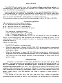
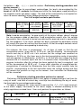
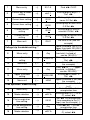
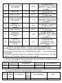
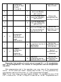
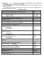
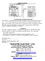
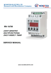
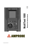
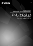
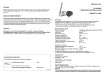
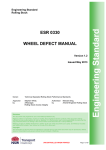
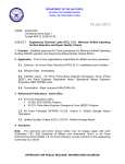
NOVATEK Ltd
Research-and-Production Company
TECHNICAL
DESCRIPTION AND
SERVICE MANUAL
RN-16T
DAILY-WEEKLY TIMER WITH VOLTAGE
RELAY
5
220V
50 Hz
RN-16T
Load
2
4
On
3
16А
6
52
1 – red LED signal for load is on;
2 – green LED “ON”;
3 – menu control buttons: →) – entry into menu, parameter input;
(→ – menu exit; ◄► – scrolling.
4 – seven-segment indicator (display);
5, 6 –connection contacts.
SAINT-PETERSBURG
APPLICATIONS
The RN-16T daily-weekly timer with the mains voltage monitoring option is a
microprocessor electronic device that functions as a voltage relay and a real time
relay. The RN-16T is designed for:
-- load energization/de-energization according to user-specified reset time /trip time;
-- de-energization an industrial and appliance single-phase 220V/50Hz load when
there are unallowable voltage variations in the mains. When the mains parameters
return to normal, the RN-16T automatically re-energizes the load.
The maximum number of events that the timer provides is: 60 = 30 ONs + 30 OFFs.
4 modes of operation:
I. A – identical events for all days of week;
II. 1-7 – different events for all days of week;
III. b -- identical events for 5 working days;
IV. C – identical events for 2 weekends of week.
The maximum number of events
in the A mode of operation: 7 х 60 = 420;
in the 1-7 mode of operation: 30 + 30=60;
in the b –C modes of operations: 5 х N + 2 х M, where N + М = 60, number of
events in the working days and weekends (for instance, if number of events in the
working days is N=40 and number of events in weekends is M=20 the maximum
number of events is
5 х 40 + 2 х 20= 240).
The RN-16T switches any power load:
• When the load power is below 3,5 kW (16A, AC1) de-energization is performed
directly through the relay output contacts that are connected in series with the
load power supply;
• When the load power is above 3,5 kW (16A) de-energization is effected by the
magnetic starter of the corresponding power (MS is not supplied in the complete
set) that has the relay output contacts to be connected in series with its coil
power supply.
DESCRIPTION
The timer is connected to the mains of 220V A.C. by the input (1-1) – (2-2)
contacts. The input contacts are provided with twin terminals for ease of wiring, i.e.
the 1-1 terminals is the first connection point and the 2-2 terminals is the
second connection point. The timer has the group of two-way break-before-make
output 3—4-4—5 contacts with a common 4-4 point. The load is connected through
the 4-5 contacts that break the load power supply circuit or the magnetic starter coil
power supply circuit. The 3-4 contacts are used in control & alarm circuits, if
necessary.
The setting of the real time, trip time and reset time, modes of operation
according to days of week as well as trip thresholds for voltage levels is effected by
the buttons «◄►, →), (→ » (see the section «Preliminary starting procedure and
service manual»).
When the relay trips for overvoltage/ undervoltage, the load is de-energized by the
break of 4-5 N. C. contacts that disconnect either the load power supply directly or
the magnetic starter coil power supply. The load will be automatically re-energized on
return to normal conditions when voltage parameters regenerate.
The 3-4-5 output contacts specification
Max. power
Max. Max. long-term Max. current
Max.current
under U~250V when contacts switch. safe voltage
under
A.C.
are closed
power
A.C./D.C.
U=30V D.C.
Cosφ=0.4
5A
5000VA
4000VA
380/150 V
5A
16A
Cosφ=1.0
Note: Load de-energization for poor quality of the mains voltage doesn’t change
the time program mode of operation. Load energization occurs after the voltage
parameters have returned to normal considering the occurred event in accord with
the time program. If the mains voltage has been removed the parameter setting
will remain the same for not less than one month. At that the output contacts return
to the initial position corresponding to dead relay.
For instance, the timer is programmed for all days of week so that the last
energization occurs every day at 22.00 p.m., and the following de-energization
occurs next day at 08.00 a.m. Let’s assume that the voltage was removed on
Monday at 22.30 p.m. (the timer was in the load energization mode of operation)
and was applied on Wednesday at 06.00 a. m. At that after the voltage has been
removed the 4-5 contacts open and the 3-4 contacts close. According to the last
program instruction after the voltage has been applied the load is energized and
will be de-energized at 08.00 a.m.. If some other algorithm of energizations/deenergizations is selected for Wednesday then the timer output contacts take the
position corresponding to the last instruction when the voltage existed and they
will remain that position as long as the nearest time instruction for Wednesday
will be executed.
Preliminary starting procedure and service manual
Preliminary starting procedure offers such option as programming of real time for
a day of week and time of natural day, reset/trip time considering the day of week,
trip thresholds for overvoltage/undervoltage.
To apply a voltage to the timer means to connect the «1-1 – 2-2» input terminals
to the mains supply. Connection to the mains supply is effected according to the
safety regulations on dead timer. User must perform the operations as follows:
Step
s
Operations
Real time setting
Button
Menu
point
Actions
Day of week (1-7); time of
natural day (00-24h, 00-59
min).
1
Menu entry
→)
E0.1.A
Find ◄► CLOC
2
Current day of week
setting
→)
daY.1
Blinking digit of days 1-7
Set ◄►
3
Current hour setting
→)
00.00
Blinking digit of tens of
hours 0-2 Set ◄►
4
Current hour setting
→)
00.00
Blinking digit of hour units
0-9 Set ◄►
5
Current minute
setting
→)
00.00
Blinking digit of tens of
minutes 0-5 Set ◄►
6
Current minute
setting
→)
00.00
Blinking digit of minute units
0-9 Set ◄►
7
Menu exit
*(→
23.47
Voltage trip thresholds setting **
8
Menu entry
→)
Any
9
Lower threshold
setting
→)
L150-210
10
Menu exit
(→
L200
11
Menu entry
→)
Any
12
Upper threshold
setting
→)
H230-290
13
Menu exit
(→
H250
Time operation modes setting **
14
Menu entry
→)
Any
15
Mode selection
→)
dAY.A
16
First energization
time setting
→)
05.30
17
First de-energization
time setting
→)
Any
18
Mode selection
→)
dAY.A
The time is set (see the
example)
Lower threshold 150-210 V
Upper threshold 230-290 V
Find ◄► L_ _ _ - lower
threshold (instead of _ _ _
can be 150-210)
Blinking point under под L
Set ◄►
Lower threshold is set (see
the example)
Find ◄► H_ _ _ - Upper
threshold (instead of _ _ _
can be 230-290)
Blinking point under H
Set ◄►
Upper threshold is set (see
the example)
Operation modes: А, 1-7,
Ь+С
Find ◄► Е01 – first
energization time
Blinking letter A (1-7, or Ь,
С), select ◄►
Set ◄► first energization
time according to the 3-7
steps( see the example), (→
Find ◄► d01 – first deenergization time
Blinking letter А (1-7, or Ь,
С), select ◄►
19
First de-energization
time setting
→)
09.15
20
Menu entry
→)
Any
21
Mode selection
→)
dAY.A
22
Second energization
time setting
→)
11.00
23
Second deenergization time
setting
→)
Any
Set ◄► first deenergization time in accord
with the 3-7 steps (see the
example), (→
Find ◄► Е02 – second
energization time
Blinking letter А (1-7, or Ь,
С), select ◄►
Set ◄► second
energization time in accord
with the 3-7 steps(see the
example), (→
Find ◄► d02 – second deenergization time
Blinking letter А (1-7, or Ь,
С), select ◄►
Set ◄► second deSecond deenergization time in accord
→)
25
12.00
energization time
with the 3-7 steps (see the
setting
example), (→
Set ◄► subsequent
Subsequent
energizations/deenergization/de→)
26
Any
energizations time
energization time
according to the 15-19
setting
steps
* * – To set the time one needs to make the resetting for seconds (to fill
seconds with zero), that’s why the →) button is pressed at zero seconds.
** – If voltage monitoring or time operation modes specification is not required
they are not set; parameter reset is effected by the label «_» input into any point
of instruction.
If necessary, operation modes can combine in different conjunctions. The only
limitation is that number of events must not exceed 60.
24
Mode selection
→)
dAY.A
For the timer programming convenience you must make a scheme of work of
your load. To this effect use the table below:
№ of
№ of
№ of deEnergization
De-energization
energization
event energization
Filling of this table for a conditional load is shown below:
№ of
№ of
№ of
deeven energizat Energization
De-energization
energit
ion
zation
1
1
First
Note
Identical
energization
time for all days
of week
01.А=06.00
energizations for all
days of week
2
1
First de-energization
time is on Monday
d01.1=06.15
3
2
First de-energization
time is on Tuesday к
d02.2=06.20
4
3
5
4
6
2
5
3
First de-energization
time is on Wednesday
d03.3=07.00
First de-energization
Identical detime is on Thirsday and
energizations for all
for the rest of days of
days of week
week d04.A=07.15
Second
energization
time for all
working days of
week
E02.Ь=08.00
7
8
Different deenergizations for
three days of week
Second deIdentical deenergization time for all
energizations for all
working days
working days
d05.Ь=09.00
Second
energization
time for
weekends
E03.С=09.00
Identical
energizations for
weekends
6
Second deenergization time for
weekends d06.С=10.00
Identical deenergizations for
weekends
Remember that number of events can not exceed 60, i. e. 30 energizations
and 30 de-energizations. The number of energizations and de-energizations
may differ.
After programming and in the operation user may view all the programmed
events. To this effect one needs step-by-step to enter (→)) every parameter by
menu buttons and to exit from menu ((→) with no parameter changed.
Note. To set time values user must specify all digits, «0» included, like that: 07.35
a.m. is to be set as «07.35», 07.35 p.m. is to be set as «19.35». Unspecified time is
displayed as «_ _ _ _». To delete an instruction one should put at least one space for
the instruction time (_7.35 – the time is deleted).
Load connection must be performed according to the safety regulations when
voltage is removed.
The programmed relay display shows the real time. The mains voltage value is
shown for 3 sec. every 15 sec.
TECHNICAL BRIEF
Nominal supply voltage, V
220
Lower threshold for supply voltage, energizing the relay, V
140
Maximum supply voltage, V
300
Trip setting range for voltage, V:
-Lower threshold
150 – 210
-Upper threshold
230 – 290
Trip threshold accuracy for voltage, V
1
Voltage measurement accuracy, no more than, V
1
Voltage hysteresis, V
+5
Fixed trip delay for overvoltage, no more than, sec
0,5
Fixed trip delay for undervoltage, sec (immunity to minor and/or shortterm undervoltage preventing excessive trippings)
12
Time setting hold-in accuracy, no more than, sec
1
Time setting accuracy, no more than, min
1
Maximum number of events in “A” mode of operation for a natural day,
including number of:
60
-energizations
30
-de-energizations
30
for a week
60Х7=420
Maximum number of events in “1-7” mode of operation for a week,
including number of:
60
-energizations
30
-de-energizations
30
Maximum number of events in “b+C” mode of operation, working days 5хN+2хM, where
+r weekends, including number of:
N+M=60
-energizations
30
-de-energizations
30
Endurance (retention of settings when supply voltage is removed, no 1 month
less than)
Number and type of contacts (N. O. – normally open, N.C. – normally 1 N.C. and
closed; two-way break-before make contacts)
1 N. O.
Protection degree:
- the relay
ІР40
- terminal box
ІР20
Output contacts life:
-- under load 16А, no less than, operations
100 000
-- under load 5A, no less than, operations
1 mln
Power consumption (under load), no more than, VA
3,0
Weight, no more than, kg
0,150
Dimensions, mm
50х88х65
-10 - +55
Operating temperature, °С
-20
- +70
Storage temperature, °С
WIRING DIAGRAM
STORAGE AND SHIPPING CONDITIONS
in manufacturer package should be stored in enclosed rooms at –
45( -- +75( C and exposed to no more than 80% of relative humidity when
there are no fumes in the air that exert a deleterious effect on package and the
RN-16T material. The Buyer must provide the protection of the timer
against mechanical damages in transit.
The RN-16T
WARRANTY
Novatek company warrants a trouble-free operation of the RN-16T timer
manufactured by it within 36 months from the date of sale, provided:
-- the proper connection;
-- the safety of the inspection quality control department seal;
-- the integrity of the case, no traces of an opening, cracks, spalls etc.
Production date_____________
Serial No____________________
Quality control department seal______________
Sale date______________________
"NOVATEK-ELECTRO" LTD.
21 Kondratievsky Prospekt,
St-Petersburg, 195197, Russia.
Tel:+7 901 300 48 46
Fax:+7 812 740 74 55
Email: [email protected]
Skype: technorus
MSN: [email protected]
Yahoo ID: [email protected]
WWW.NOVATEK-ELECTRO.COM