1
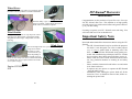
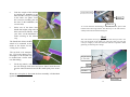
HT-KumaP Harvester User Manual REID LINE EAST, RD 5 FEILDING 4775, New Zealand Phone (06)323 2509 Fax (06)323 2709 Email [email protected] 11/2012 © Jenquip 2005 Wheel Fence Used on field type crops where crop snagging around the wheel can be a problem i.e Pasture trial blocks HT-KumaP Harvester Introduction High Fences Fitted for bulky crops or where wind blow can be a problem. 170mm high, shown here fitted with cover hold down points Congratulations on the purchase of your Harvester Concepts Ltd HT—KumaP Harvester. This machine is of high quality and will reward you with reduced effort and greater efficiency in your harvesting. Learning to operate your HT—KumaP won't take long. You will soon find it to be an invaluable tool. Wind Shields Help prevent wind blow as crop drops into collection bag / bins. Removable, one fitted each side. Weighted at bottom edge / independent of collection bag Important Safety Note Wind Cover The see through mesh cover prevents the cut crop being blown off the harvester by wind. Can be fitted in 2 positions depending if the in feed reel is fitted or not. Second picture shows wind shields fitted as well but they are not required unless the wind is severe (time to stop!) Notes Engine G23LH55 S/N 20 Read and understand all the instructions before using the HTKumaP The HT– KumaP should only be used for the purposes for which it was designed. Use it for no other purpose (e.g. it is not a grader blade or battering ram!). We have manufactured the HT-KumaP using quality materials and manufacturing techniques however if faults do occur please have them corrected before you use it. Please read the Power Head instruction book before use. Pay particular attention to running in and safety notes. Please read this instruction book before use and retain it for future reference. It requires only one person to operate the HT-KumaP - keep all others away! Immediately after turning the power head off, fit the cutter bar cover. It should be removed last, before restarting the power head. 1 Index Page 1 2 3 Introduction / Safety notes Index / Specifications Conditions of sale and guarantee 4 Your HT-KumaP Harvester Consists Of 5 Uses of the HT-KumaP / Assembly 7 Dismantling 9 Start up / Fault finding 11 Maintenance 12 Preventative Maintenance 13 Transporting 14 Options, notes Transport Wheel When moving some distance between harvests an optional travel wheel can be fitted. This allows your harvester settings to be retained. The travel wheel is simply plugged into the quick release fitting on the LH front wheel mount (modified). This raises the cutter bar well above vegetation and allows easy manoeuvring. If more ground clearance is required the LH wheel is adjusted down. Specifications Cutting height (cutter bar above wheel ground level): 40 to 400mm without bag dragging on crop. Cut width:- 800mm (optional 1200mm) Weight, dry:- 54.5 Kg (optioned 58Kg) Wheel track:- 1130mm (optioned 1540mm) Belt speed:- 19.5 m/Min Dimensions:Ready to use:- 1390mm max. width (optional 1780mm) 2350 long over wheels and control handle Crop lifters extend length to 2870mm To top of control handle 830—970– 1085mm For Freighting:- On pallet Approx 90Kg (optioned 96Kg) Removeable Top Fence Used mainly on the HT -Cress. Used when the cut crop is hand gathered for bundling or packaging. 1620x1390x800mm = approx 1.8m³ (optioned, folded up: 1740x1560x800mm= 2.2m³) 2 19 Conditions of Sale and Guarantee Lift Handle, Used for lifting the front of the Harvester. It fits into the front legs, as shown, and is retained by a lynch pin. Reposition as required. Also acts as protection for the engine. Full Width model As above but is retained by nyloc nuts. Can be left in place if it doesn’t interfere with the crop. Reposition as required. Lift Handle 18 Your HARVESTER CONCEPTS LTD product is guaranteed to be free from defects in materials and/or workmanship under normal use and service for a period of 6 months from date of initial purchase. HARVESTER CONCEPTS LTD’S liability and obligation is limited to problems which HARVESTER CONCEPTS LTD acknowledges to be defective under the guarantee conditions either to - the free replacement or repair (where practicable) at the HARVESTER CONCEPTS LTD premises of any parts returned within the guarantee period - or shipment of replacement parts to the customer, as mutually agreed to. Supply of non standard parts or services from other than HARVESTER CONCEPTS LTD are not covered under the guarantee conditions unless prearranged, in writing, with HARVESTER CONCEPTS LTD Shipment of product to HARVESTER CONCEPTS LTD is the consumers responsibility and cost Guarantee conditions are void for any of the following reasons:Abnormal use of the product Accident damage or vandalism Modifications or unauthorised repairs to the product or its components Where component "seconds" have been supplied Normal wear and tear HARVESTER CONCEPTS LTD cannot be held liable for any damage caused to people or other property during use of the product or as a result of any defect or malfunction of product or components supplied by HARVESTER CONCEPTS LTD. Use of the product is solely the users responsibility. Other losses such as delays in work, incorrect or misleading information, omissions and errors, HARVESTER CONCEPTS LTD is not liable for. This guarantee is expressed in lieu of all other guarantees expressed or implied and all other obligations and liabilities on HARVESTER CONCEPTS LTD's part and specifically excluding consequential damage. HARVESTER CONCEPTS LTD makes no guarantee of merchantability or fitness for purpose and is not responsible to any purchaser of its products for any undertaking, representation or guarantee, except those stated in these terms, made by any person, dealer or body corporate selling or dealing with its products 3 in any manner whatsoever. Collection Tray Your HT-KumaP Harvester Consists Of: Handlebar frame & lift handle Conveyor and cutting head assembly Two large wheels, small wheels / mounts Collection bag, one (or bin option) HT– KumaP instruction book Power Head instruction book and spanners Optional Collection bags • Infeed Reel Travel wheel • Collection tray/ bin holder #1200 cutting width • Full width Lift Handle Crop lifters • Side shift for crop lifters Handlebar frame Engine throttle Collection bag Triknob Large wheels Conveyor / cutter head assembly Support strap Collection bin Adjustments The cuttings come off the conveyor and as they arrive on the collection tray the operator gathers them up. Depending on the operation and number of workers the harvest may be near continuous or it may be a series of small forward movements followed by bundling operations. The bin holder takes 2 Recrate 47 or 75 size bins. Adjustments are provided, down each side of the tray, to achieve the optimum tray / bin positions. Small wheels Cutter bar 4 17 To Adjust:Slacken belt tensioner (the vee belt can remain in place unless the reel is being totally removed). Holding the reel nearer the pulley side, remove the height adjusting pins and slide the reel to its new height setting. Reinstall pins ensuring reel is level, and tighten tensioner. Note: For low reel or cutting heights the crop lifters may have to be removed or the lifter tine bent out of the way of the reel. To remove, slacken belt tensioner, remove belt, remove height adjusting pins and lift off reel. Fitting is in reverse but take care not to lose mounts and to fit them the correct way around. Bin Holder Holds the bins, Recrate 47 or 75’s Uses of the HT—KumaP It’s uses are about as varied as there are different crops. However some main uses include General Trimming. Pruning crops or shrubs to height Herb Harvesting. the HT will straddle the row to be harvested, cutting the crop to a uniform height and placing the trimmings in the collection bag Taking Cuttings. Cut and collect cuttings from beds ready for pricking out Clean Up. Cutting rank grass or collecting up surplus vegetation Assembly #800 bin holder shown #1200 model similar to next picture. Collection Tray / Bin Holder This is used when the operator requires to hand gather or bundle the cuttings and manually place them into a collection bin. It is usually used in conjunction with the in feed reel. 16 Unpack the harvester ensuring you receive all the parts and that they have not been damaged in transit. Layout the components on the ground in their rough position. Note: the front wheels may already be fitted especially if the reel option is fitted. 5 Take the weight of the machine by holding the handlebar in one hand and the conveyor assembly in the other—see photo. Lower the conveyor assembly pins into the slots on the handlebars (one on each side) Select one of the three lower handle bar heights, align relevant holes and insert triknobs. Adjust your force on the handlebars to make screwing in the triknobs easy. Triknob Mount bolt To convert from the fixed fitting to side shift, the bolt, spacers and triknob need removing and the Arm fitted up to the side shift assembly and secured with the Fitting nut. Reel The reel ensures the crop is pushed onto the conveyor and is not lost over the front of the cutter bar. It also lays the crop onto the conveyor roughly in the same direction which is required if hand gathering or bunching the cuttings The fourth hole allows the RH wheel to be mounted on the inside of the frame for harvesting close to fences. The top hole is for transporting. It gives the shortest overall length so the KumaP can be loaded onto a trailer without dismantling. Crop Lifter Arm Height adjuster (1 each side) Fit the big wheels; with the axle through each wheel and spacer fitted, insert the axle into the wheel mount hole and fit the small lynch pin to secure it. Reel Belt Tensioner Vee Belt Where the reel option is fitted and the front assembly is folded back against the conveyor belt:Lift Handle 6 15 Options Crop Lifters: The two crop lifters are handed, with the tines pointing inwards, towards the conveyor. Installation is a simple case of placing the bolt through the lifter arm, through the larger spacer, through the main harvester chassis, the thin spacer and secured by the triknob. LH Crop Lifter A retainer, fitted at the wheel mounting nut, supports the crop lifter when the front of the harvester is lifted for turning corners etc. The retainers also prevent the crop lifters dropping onto the cutter bar. Note: If the wheels / retainers are removed for any reason the crop lifters should first be removed to avoid any possibility of damaging the cutter bar. 1. With a person on each side of harvester, evenly pivot the reel / cutter head forward and upwards. 2. Adjust the cutter head / blade to the correct angle (see levelling the cutter bar on page 8). Fit the 2 blade levelling adjusting bolts (in cardboard box) – see picture below 3. Tighten the 2 lock nuts if necessary 4. To fit the drive shaft to gearbox; remove the small bolt on the side of the gearbox housing. Insert the driveshaft into the housing until the hole on the side of the driveshaft aligns with the bolt hole (you may need to twist the driveshaft or move the conveyor / chain drive a little to get the drive shaft to mesh with the internal drive, to allow the drive shaft to be fully inserted). Refit the retaining bolt. Blade level adjusting bolt Crop Lifter Side Shift These are made to suit the application but standard adjustment is 140mm each side. The lifter retainer only works when the crop lifter is adjusted fully outwards (Do this at when you wish to lift the front of the harvester). Lock Nut Fit the small front, height adjusting wheels if not already fitted. Various positions are available for setting the cutting height. Position wheel assembly accordingly and fit lynch pins to retain them. There are 2 holes provided on the framework allowing finer height adjustment. Fitting nut 14 7 Transporting Route the throttle cable in gentle curves and secure the throttle control on the Left Hand side of Handlebars using wing nut. Secure the cable with the Velcro strap supplied By adjusting the machine height the cutter bar may not be horizontal (level). This could result in double, untidy cuts and harder cutting. To level the cutter bar, remove the adjusting bolts (1 each side) loosen the lock nuts, rotate the power head to it’s next position, refit bolts and tighten the lock nuts. Fit collection bag. The alloy tubes fit in the “U” shaped brackets on the frame. Ensure it is fitted the correct way round. The bag support tubes have spring loaded plungers in their ends. Push the tubes to the LH (engine) side to compress the plungers, for fitting or removing the collection bag. Dismantling When transporting the Harvester it does not have to be dismantled. It can be secured on a tray or trailer using tie downs from appropriate points as shown in the pictures. Rear tie down point Front leg—use bolt or pin through leg for the tie down to pull against is in reverse of assembly. Take care not to damage the throttle cable. If the reel is fitted wrap the tie down around the mounting bracket as shown. Freighting on the back of a utility vehicle is preferred. The HT-KumaP is very light and if transporting on a trailer it is not heavy enough by itself to make the trailer springs work i.e. it will get badly shaken about. On rough road / tracks this could cause structural damage. One solution is to put a extra weight on the trailer as well as the harvester so the springs actually work! 8 13 Slide the conveyor belt off. Clean conveyor belt and rollers. Reassembly is the reverse procedure. Start Up Preventative Maintenance 1. With the machine adjusted ready for harvesting, remove the cutter bar cover. You will become reliant on the harvester to do its job and if a breakdown was to occur you could find yourself in an awkward predicament. We recommend regular maintenance to help avoid breakdowns. 2. The power head should be refuelled and started in accordance with the manufacturers handbook. Note: Especially during running in , vary the throttle setting - don’t rev continuously. 3. The engine must be stopped and the cutter bar cover fitted before any adjustments are done. CAUTION: Do not approach the front of the machine with the engine running. Always switch it off and fit the cutter bar cover. 4. Let the engine warm up for a minute. Use the throttle control to rev the engine up. As the engine is revved up the conveyor and cutter bar will start. As well as the maintenance on the previous page we recommend: If used regularly, at least annually, (Heavy use every 4 months) stripping the reciprocating gearbox at the end of the cutter bar. Regardless of condition, replace all bearings and the 2 drive links which also hold bearings. Preload the housing with some grease but not too much or it can jam the drive. Check cutter bar bolts for ware and replace nuts, bolts and washers as required To stop the conveyor and cutter bar, throttle the engine back with the throttle lever. Engine stop switch is on the engine 5. The collection bags are weighted with lead shot so they all weigh 1Kg. This is for ease of weighing samples. For access the spring loaded plunger can be removed for adding / reducing weight if required. Fault Finding Engine will not start - Refer to manufacturers handbook 12 Check ignition switch is on. Fuel in tank? Correct use of choke? Fouled spark plug? 9 Maintenance Conveyor not driving correctly Engine revving up? Conveyor belt too tight. It should only be tight enough to grip on the drive roller without slipping. Before adjusting the belt tension slacken the drive chain tension. Remember that there is a belt tensioner on each side of the machine. Both tensioners must be adjusted evenly - use a ruler. To adjust—release lock bolt and adjust tension bolt accordingly. Retighten lock nuts and lock bolts and then adjust chain tension. Wash down the HT-KumaP harvester after use. Only wash enough to remove dirt. Over washing could induce corrosion. Sealed bearings are utilised but water under pressure could penetrate them. Check the cutter blades for looseness. If necessary adjust as follows. Loosen nut (1) Tighten screw (2) and turn back 1/2-3/4 turn Tighten nut (1) Lubricate blades, start engine and run blades for 1 minute at full speed. Stop the engine and carefully touch each nut (2) in turn. If temperature moderate, clearance is good; too hot to touch - readjust turning (2) back a little and retest. Belt tension Bolt The cutter bar should be lubricated with a food compatible lubricant whenever refuelling and before storing. Silicon lubricants can be applied to hinge points, sliding areas etcetera. Lubricate the power head every 2 hours- use Ochiai original grease. There are 3 grease nipples: Two on the Power Head and one on the chain drive gearbox. Apply a drop of oil to the throttle cable adjacent to the carburettor Sharpen the cutter bar if required. The wheels and handle bars can be removed for storage or freighting. The collection bag should always be emptied, washed if necessary and allowed to dry Check chain tension / adjust. Tensioner can be rotated if worn. Lock Bolt, belt tension TriKnob Chain tension lock bolts Conveyor belt loads up / doesn’t track correctly—it moves to one side. The belts now have a tracking strip on them but they can still load up or become stressed if not tensioned correctly uneven belt tension. Belt will always move towards the tightest side—slacken it off (see above). Build up of material on rollers. Slacken belt tensioners and remove belt (remove RH conveyor fence and side rail, slide belt off RH side). If you require further assistance or spare parts, please call Harvester Concepts Ltd 10 To clear contamination from around conveyor rollers you need to:- 1. Slacken the conveyor belt. This is done at the 2 adjusters at the top end of the conveyor. Note their original setting so you can adjust back to this later. 2. Remove the Right hand (conveyor) frame - as seen from operators position. Best to support the top end of conveyor on a saw horse or chair. There are only a few bolts to remove. 11