1
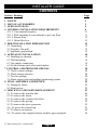
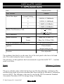
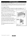
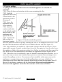
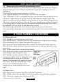
600B687/11
INSTALLER GUIDE
Model 339
Heartbeat Oxysafe 2
LIVE FUEL EFFECT GAS FIRE
(GC No. 32-032-29)
We trust that this guide gives
sufficient details to enable this
appliance to be installed and
maintained satisfactorily. However, if
further information is required, our
Baxi Fires Division Technical
Helpline will be pleased to help.
Telephone 08706 061 065 (National
call rates apply in the United
Kingdom).
In the Republic of Ireland
Telephone 0044 8706 061 065.
THIS APPLIANCE IS FOR USE WITH
NATURAL GAS (G20).
THIS APPLIANCE IS SUITABLE ONLY
FOR INSTALLATION IN THE UNITED
KINGDOM (GB) AND THE REPUBLIC
OF IRELAND (IE).
INSTALLER: Please leave this guide with the owner
© Baxi Heating U.K. Limited 2007.
INSTALLER GUIDE
© Baxi Heating U.K. Limited 2007.
All rights reserved. No part of this publication may be reproduced in any material form
(including photocopying), stored in any medium by electronic means (including in any
retrieval system or database) or transmitted, in any form or by any means, whether
electronic, mechanical, recording or otherwise, without the prior written permission of
the copyright owner.
Applications for the copyright owner's permission to reproduce any part of this
publication should be made, giving details of the proposed use, to the following address:
The Company Secretary, Baxi Heating UK Limited, Pentagon House, Sir Frank Whittle
Road, Derby, DE21 4XA.
Warning: Any person who does any unauthorised act in relation to a copyright work
may be liable to criminal prosecution and civil claims for damages.
Baxi Fires Division, Erdington, Birmingham B24 9QP
www.firesandstoves.co.uk
Because our policy is one of constant development and improvement, details may vary slightly from those
given in this publication
© Baxi Heating U.K. Limited 2007.
Page 2
INSTALLER GUIDE
Safety First.
Baxi Fires Division fires are CE Approved and designed to meet the appropriate British
Standards and Safety Marks.
Quality and Excellence.
All Baxi Fires Division fires are manufactured to the highest standards of quality and
excellence and are manufactured under a BS EN ISO 9001 quality system accepted by
the British Standards Institute.
The Highest Standards
Baxi Fires Division is a member of the Society of British Gas Industries which works to
ensure high standards of safety, quality and performance.
Careful Installation
Baxi Fires Division is a CORGI registered company. All our gas fires must be
installed by a competent CORGI Registered Installer in accordance
with our Installer Guide and should not be fitted directly on to a
carpet or floor of combustible material.
© Baxi Heating U.K. Limited 2007.
Page 3
INSTALLER GUIDE
CONTENTS
Section Heading
Page
1
2
3
4
SAFETY
LIST OF ACCESSORIES
APPLIANCE DATA
GENERAL INSTALLATION REQUIREMENTS
4.11.2 Conventional fireplace.
4.11.3 Wall mounting to conventional or pre-cast flues.
4.11.4 Precast flues.
4.11.5 Metal flue box.
5 PRE-INSTALLATION PREPARATION
5.1 Unpacking.
5.2 Fireplace flue pull.
5.3 Appliance preparation.
6 APPLIANCE INSTALLATION
6.1 Installing to a hearth.
6.2 Wall mounting.
6.3 Gas supply connection.
6.4 Fit the ceramic fuel effect and window.
7 CONTROL AND PRESSURE CHECKS
7.1 Check control settings.
7.2 Check burner pressure.
7.3 Test for spillage.
7.4 Flame supervision and spillage monitoring system.
8 FINAL ASSEMBLY AND REVIEW
8.1 Fitting the fascia.
8.2 Final review.
9 SERVICING AND PARTS REPLACEMENT
9.1 To remove the window unit.
9.2 To remove the fascia.
9.3 To remove the ceramic fuel effect.
9.4 To remove the gas tap.
9.5 To remove the piezo generator.
9.6 To grease the control tap.
9.7 To remove an injector.
9.8 To remove the complete burner module, pipes and pilot.
© Baxi Heating U.K. Limited 2007.
Page 4
5
5
6
8
11
11
12
12
15
15
15
15
18
18
18
19
19
20
20
20
20
22
22
22
22
23
24
24
24
25
25
25
26
26
INSTALLER GUIDE
1 SAFETY
Installer
Before continuing any further with the installation of this appliance please read
the following guide to manual handling:
!
!
!
!
!
!
!
!
!
The lifting weight of this appliance is 15.43 kg.
One person should be sufficient to lift the fire. If for any reason this weight is
considered too heavy then obtain assistance.
When lifting always keep your back straight. Bend your legs and not your back.
Avoid twisting at the waist. It is better to reposition your feet.
Avoid upper body / top heavy bending. Do not lean forward or sideways whilst
handling the fire.
Always grip with the palm of the hand. Do not use the tips of fingers for support.
Always keep the fire as close to the body as possible. This will minimise the
cantilever action.
Use gloves to provide additional grip.
Always use assistance if required.
2 LIST OF ACCESSORIES
Description
Spigot extension
© Baxi Heating U.K. Limited 2007.
Part number
0595191
Page 5
INSTALLER GUIDE
3 APPLIANCE DATA
Gas
Natural (G20)
Inlet Pressure
Gross Heat Input
20mbar
Control Setting
4
5.05kW (17,200Btu/h)
3
3.45kW (11,800Btu/h)
2
1.80kW (6,100Btu/h)
1
1.55kW (5,300Btu/h)
Burner Test Pressure (Cold)
17.2 + 0.75mbar
(6.9 + 0.3in w.g.)
Gas Connection
Burner Injectors
8mm pipe
Upper
Bray Cat. 99 Size 115
Lower
Bray Cat. 99 Size 230A
Pilot & Atmosphere Sensing Device
Ignition
SIT Ref. OPNG9419
Piezo-electric
integral with gas tap
Aeration
Non-adjustable
The appliance data label is on the inner face of the back panel at the lower left hand
side. It is visible when the fascia is removed.
The efficiency of this appliance has been measured as specified in BS 7977 - 1 and the
result is as below :
Model
339
Efficiency % (Gross)
71
The gross calorific value of the fuel has been used for this efficiency calculation. The
test data from which it has been calculated has been certified by Advantica Certification
services (0087). The efficiency value may be used in the UK Government's Standard
Assessment Procedure (SAP) for energy rating of dwellings.
© Baxi Heating U.K. Limited 2007.
Page 6
INSTALLER GUIDE
The conversion of net efficiency to gross was achieved by multiplying the net
efficiency by the following conversion factor from Table E3 of SAP 2005, rounding
down to the nearest whole number.
Gas
Conversion factor from net to gross efficiency
Natural Gas
0.901
This product uses a burner gasket and burner surface containing Refractory
Ceramic Fibres (RCF), which are man-made vitreous silicate fibres. Excessive
exposure to these materials may cause irritation to eyes, skin and respiratory tract.
Consequently, it is important not to touch or disturb the burner surface to ensure
that the release of dust is kept to a minimum. To ensure that the release of fibres
from these RCF articles is kept to a minimum, during installation and servicing we
recommend that you use a HEPA filtered vacuum to remove any dust and soot
accumulated in and around the fire before and after working on the fire. Do NOT
vacuum the burner surface. When replacing the the burner surface we recommend
that the replaced items are not broken up, but are sealed within a heavy duty
polythene bag, clearly labelled as RCF waste. RCF waste is classed as a stable, nonreactive hazardous waste and may be disposed at a landfill licenced to accept such
waste. Protective clothing is not required when handling these articles, but we
recommend the use of suitable gloves to prevent irritation. We also recommend you
follow the normal hygiene rules of not smoking, eating or drinking in the work
area and always wash your hands before eating or drinking.
This appliance does not contain any component manufactured from asbestos or
asbestos related products.
© Baxi Heating U.K. Limited 2007.
Page 7
INSTALLER GUIDE
4 GENERAL INSTALLATION REQUIREMENTS
4.1 The installation must be in accordance with these instructions.
For the user’s protection, in the United Kingdom it is the law that all gas appliances are
installed by competent persons in accordance with the current edition of the Gas Safety
(Installation and Use) Regulations. Failure to install the appliance correctly could lead
to prosecution. The Council for the Registration of Gas Installers (CORGI) requires its
members to work to recognised standards.
In the United Kingdom the installation must also be in accordance with:
!
All the relevant parts of local regulations.
!
All relevant codes of practice.
!
The relevant parts of the current editions of the following British Standards:BS 715
BS EN 1806 which replaces BS 1289 Part 2
BS 5440 Part 1
BS 5440 Part 2
BS 6891
BS 1251
BS EN 1856 Part 1 which replaces BS 4543 Part 2
BS 5871 Part 1
BS EN 1858 which replaces BS 1289 Part 1
BS 6461 Part 1
In England and Wales, the current edition of the Building Regulations issued by
!
the Department of the Environment and the Welsh Office.
!
In Scotland, the current edition of the Building Standards (Scotland) Regulations
issued by the Scottish Executive.
!
In Northern Ireland, the current edition of the Building regulations (Northern
Ireland) issued by the Department of the Environment for Northern Ireland.
!
In the Republic of Ireland the installation must be carried out by a competent
person and installed in accordance with:
a)
The current edition of IS 813 “Domestic gas installations”.
b)
All relevant national and local rules in force.
c)
The current building regulations
Where no specific instructions are given, reference should be made to the relevant
British Standard Code of Practice.
4.2 If the appliance is intended to be installed to a chimney that was previously used
for solid fuel, the flue must be swept clean prior to installation. All flues should be
inspected for soundness and freedom from blockages.
© Baxi Heating U.K. Limited 2007.
Page 8
INSTALLER GUIDE
4.3 Any chimney dampers or restrictors should be removed. If removal is not
possible they must be fixed in the open position.
4.4 Normal adventitious ventilation is usually sufficient to satisfy the ventilation
requirements of this appliance. In GB reference should be made to BS 5871 Part 2 and
in IE reference should be made to the current edition of IS 813 “Domestic gas
Installations” which makes clear the conditions that must be met to demonstrate that
sufficient ventilation is available
4.5 Note that soft wall coverings (e.g. embossed vinyl, etc.) are easily affected by
heat. They may scorch or become discoloured when close to a heating appliance. Please
bear this in mind when installing.
4.6 The appliance must not be installed in any room, which contains a bath, or shower
or where steam is regularly present.
4.7 An extractor fan may only be used in the same room as this appliance, or in any
area from which ventilation for the appliance is taken, if it does not affect the safe
performance of the appliance. Note the spillage test requirements detailed further on in
this manual. If the fan is likely to affect the appliance, the appliance must not be
installed unless the fan is permanently disconnected.
Figure 1 Dimensions and clearances
© Baxi Heating U.K. Limited 2007.
Page 9
INSTALLER GUIDE
4.8 The minimum allowable distance from the outside of the appliance fascia to a
corner wall having combustible material or any other combustible surface which
projects beyond the front of the appliance is 100mm at either side (See figure 1). A
clearance of 100mm should be maintained at the right side in all installations to allow
satisfactory access to the control knob. Although no side clearance is necessary to noncombustible surfaces on the left hand side we recommend a 100mm clearance for
service access to the fascia side fixings.
4.9 The appliance is fitted with an A.S.D (Atmosphere sensing device). If the
appliance closes down after a period of operation for no apparent reason, the consumer
should be informed to stop using the appliance until the installation and appliance have
been thoroughly checked. The A.S.D will shut the appliance down if an unacceptable
amount of harmful products of combustion accumulate. Under no circumstances should
the A.S.D be altered or bypassed in any way. Only genuine manufacturers replacement
parts should be fitted.
4.10 Allow a minimum clearance of 150mm from the top surface of the appliance
fascia to the underside of any shelf whether it is made from non-combustible materials.
This clearance is necessary to allow the fascia to be lifted off for servicing.
For a shelf made from wood or other combustible materials deeper than 150mm, the
minimum clearance must be as below. Important : No combustible material (e.g.
Wallpaper, plastic tiling, wood panelling etc.) must be used on the fireplace wall below
the shelf.
• For a shelf up to 150mm deep: Minimum clearance = 150mm.
• For a shelf deeper than 150mm: 150mm + 12.5mm for every 25mm depth over
150mm (See Graph 1).
Graph 1. Combustible shelf clearances
© Baxi Heating U.K. Limited 2007.
Page 10
INSTALLER GUIDE
4.11 In the United Kingdom, as supplied, this appliance can be installed in the
following situations: Note: A spigot extension is available (Baxi Fires Division part number 0595191). When
fitted this shall extend through the closure plate for at least 15mm and have a minimum
clearance of 50mm from the end to any surface.
4.11.1 The appliance must be mounted on a non-combustible hearth except when the
conditions in section 4.11.3 are met (N.B. conglomerate marble hearths are considered
as non-combustible). The hearth must be at least 680mm wide x 300mm deep. The
hearth material must be at least 12mm thick. The periphery of the hearth (or fender)
should be at least 50mm above floor level to discourage the placing of carpets or rugs
over it.
The appliance can be fitted to a purpose made proprietary class “O” 150°C surround.
4.11.2 Conventional fireplace.
The fireplace opening must be within the following dimensions:
Width
Max.
Min.
Height
432mm
305mm
Max.
Min.
610mm*
550mm
*The total height of the closure plate is 660mm and will accommodate a maximum
opening height of 650mm (This allows a 10mm overhang). Heights above
623mm (Inclusive of sealing tape) will leave the sealing tape and closure plate visible
above the appliance.
4.11.3 Wall mounting to conventional or pre-cast flues.
The wall opening must be within the following dimensions:
Width
Max.
Min.
Height
432mm
305mm
Max.
Min.
610mm*
334mm
*The total height of the closure plate is 660mm and will accommodate a maximum
opening height of 650mm (This allows a 10mm overhang). Heights above
623mm (Inclusive of sealing tape) will leave the sealing tape and closure plate visible
above the appliance.
The bottom of the appliance must be at least 100mm above the finished floor covering.
See figure 1. This requires the top of the opening to be at least 650mm above the
© Baxi Heating U.K. Limited 2007.
Page 11
INSTALLER GUIDE
finished floor covering. Any opening visible below the appliance may be closed in but
the depth of the catchment space within the wall opening must be as shown in figure 2.
4.11.4 Precast flues.
The appliance can be installed to a fireplace that has a properly constructed precast
concrete or clay flue block system conforming to BS1289 or BS EN 1806. The
appliance is suitable for installations conforming to older versions of BS1289 as well as
the current standards. The flue blocks must have a minimum width not less than 63mm
and a cross-sectional area not less than 13,000mm2. Older editions of BS1289 required
a cross-sectional area of 13,000mm2. The current revision of the standard requires
16,500mm2. This appliance is suitable in both cases.
The chimney should be one or two storey high but not less than 3m vertical height and
be correctly terminated. No mortar fangs between the blocks should be extruded into the
flueway. If raking blocks are used, they must be fitted in accordance with the
manufacturer’s instructions. Mortar must not be allowed to drop down and accumulate
in the raked positions.
The fireplace opening must be within the following dimensions:
Width
Max.
Min.
Height
432mm
305mm
Max.
Min.
610mm1
550mm2
1 The total height of the closure plate is 660mm and will accommodate a maximum
opening height of 650mm (This allows a 10mm overhang). Heights above
623mm (Inclusive of sealing tape) will leave the sealing tape and closure plate visible
above the appliance.
2 Any opening visible below the appliance may be closed in.
4.11.5 Metal flue box.
The appliance can be installed to a metal flue box conforming to BS715 with a
minimum internal depth of 200mm. Incombustible mineral wool insulation of not less
than 50mm thickness must be applied to the top surface of the firebox and it must stand
on a non combustible hearth. There must be an air gap clearance of 50mm all round the
outside of the box and above the top insulation to any combustible material.
The opening must be within the following dimensions:
Width
Max.
Min.
© Baxi Heating U.K. Limited 2007.
Height
432mm
407mm
Max.
Min.
Page 12
610mm*
560mm**
INSTALLER GUIDE
* The total height of the closure plate is 660mm and will accommodate a maximum
opening height of 650mm (This allows a 10mm overhang). Heights above
623mm (Inclusive of sealing tape) will leave the sealing tape and closure plate visible
above the appliance.
** This fire has been tested for use on the ‘Rite-Vent’ 7T95125 metal flue box and
found to be satisfactory.
4.12 If the fireplace opening is greater than the acceptable dimensions given in
this guide, do not use the back of a fire surround or marble to reduce the opening.
This may cause cracking of the surround back or marble.
4.13 The following flues are suitable:
!
225mm x 225mm conventional brick flue.
If a flue liner is used, it must be a minimum of 125mm diameter. The liner must be
sealed to the surrounding area above the fireplace opening and to the top of the
chimney. An approved terminal must be fitted.
!
A properly constructed precast flue conforming to B.S 1289 or BS EN 1806.
!
A flue pipe with a minimum diameter of 127mm. See B.S 6461 Part 1 for suitable
materials. Metal flue pipes must comply with B.S 715. See section 4.11.5 of this guide
for flue box opening sizes.
4.13.1 The flue must conform to BS 5440: Part 1 in design and installation.
The flue, measured from the bottom of the fireplace opening to the bottom of the
terminal, shall be not less than 3m in actual vertical height. When calculated in
accordance with BS 5440: Part 1 Annex A, the minimum equivalent height of the flue
shall be 2.0m of 125mm dia. flue pipe.
4.13.2 The flue must be clear of any obstruction and its base must be clear of debris.
4.13.3 The flue must be completely sealed so that combustion products do not come
into contact with combustible materials outside the chimney.
4.13.4 The flue must serve only one fireplace.
4.13.5 Proprietary terminals must comply with BS 715 or BS 1289. Any terminal or
termination must be positioned in accordance with BS 5440 Part 1 to ensure that the
products of combustion can be safely dispersed into the outside atmosphere. Where the
appliance is connected to an unlined brick chimney it is generally unnecessary for the
chimney pot to be replaced or for a terminal to be fitted unless the flue has a diameter
smaller than 170mm.
4.14
If the fireplace opening is an underfloor draught type, it must be sealed to stop
any draughts.
4.15 The flue spigot and any spigot extension must be capable of passing through the
closure plate by at least 15mm with a minimum clearance of 50mm between its open
end and the nearest obstruction.
© Baxi Heating U.K. Limited 2007.
Page 13
INSTALLER GUIDE
There must also be a minimum clearance of 165mm between the back of the closure
plate and the back of the catchment space.
On conventional flues the catchment space below the flue spigot must extend at least
250mm downward measured from the bottom of the flue spigot (See figure 2).
4.16 The front of the fireplace should be flat over
an area sufficient to ensure a good seal with the
closure plate. The flat surface should extend for a
height equal to that of the closure plate plus 20mm
and for a width equal to that of the closure plate
plus 40mm.
4.17 If the fire is to be fitted against a wall with
combustible cladding, the cladding must be
removed from the area shown in figure 3.
4.18 The space between the fireplace front face
and the back of the appliance fascia must not be
filled in.
Figure 2 Fireplace catchment
space.
Figure 3. Area to be free of
combustible cladding
© Baxi Heating U.K. Limited 2007.
Page 14
INSTALLER GUIDE
5 PRE-INSTALLATION PREPARATION
5.1 Unpacking.
The carton contains the following:1off
Fire assembly.
1off
Ceramic fuel effect (In packaging inside firebox).
1off
Closure plate.
1off
Smoke match tube.
1off
Olive & olive nut for gas line connection
1off
Literature pack
Remove all the items carefully to prevent damage. Some items may be contained in the
packaging fitments -Examine the packaging carefully before discarding. Check that all
the items are present and undamaged.
5.2 Fireplace flue pull.
Close all doors and windows in the room in which
the appliance is to be installed. After confirming with
a match that smoke is drawn into the flue, light a 13
gram smoke pellet and check that there is a definite
flow through the flue. Verify outside that the smoke
exits from one terminal only and that the termination
is suitable. Observe, where possible, upstairs rooms
and loft spaces for signs of escaping smoke
Figure 4. Transit screws.
indicating a defective flue. If there is not a
definite flow warm the flue for a few minutes and
repeat the smoke pellet test. If there is still no
definite flow the flue may need remedial work –
Do not fit the appliance until there is a definite
flow through the flue.
5.3 Appliance preparation.
5.3.1. Stand the fire upright.
5.3.2. Remove the two transit screws from the
upper back panel extensions (See figure 4).
5.3.3. Detach the window surround (See figure 5).
a)
Remove the two knurled screws
immediately below the outer fascia canopy.
b)
Lift the surround clear of the slots in the
outer fascia apron
5.3.4. Remove the control knob by pulling clear
Figure 5. Window surround
of the gas tap spindle.
removal.
© Baxi Heating U.K. Limited 2007.
Page 15
INSTALLER GUIDE
5.3.5. Remove the control bezel by unscrewing two
screws (See figure 6).
5.3.6. Detach the fascia by removing the screws at the
fascia sides (See figure 6).
5.3.7. Pull the bottom of the fascia forward while
springing the bottom corners outward to clear the
fixing brackets. Lift the fascia upward and forward to
clear (See figure 6). Place carefully to one side.
5.3.8. Remove the window unit by removing the
screws each side of the window frame and lifting the
unit clear.
5.3.9. Remove the ceramic coal fuel effect pack from
the firebox and keep it safe.
5.3.10. Check ignition spark
Before attempting to install, it is worth checking that
the piezo electric spark ignition system operates
satisfactorily.
To initiate the spark, temporarily refit the control knob
to the tap spindle. Depress the control knob and while
keeping it depressed, turn anticlockwise through
approximately 60° to the 1/IGN position. A spark
should track from the electrode pin to pilot burner. If
there is no spark or incorrect tracking, check that the
spark gap is between the limits shown in figure 7. If
the spark gap is correct, check the ignition wiring.
Remove the control knob after checking.
Figure 6. fascia removal.
5.3.11 For wall mounted appliances.
Remove the levelling screws and locknuts from below
the feet.
5.3.11 If the fire is fitted to a recessed fireplace, an
extension flue spigot up to a maximum total length of
125mm may be used. The extension must be a tight fit
over the flue spigot and be secured by two self tapping
screws. Note the minimum clearance required as shown
in figure 2.
5.4 Fitting the closure plate.
(See figure 8).
Figure 7. Pilot spark gap
The closure plate has an opening at the bottom for a
central gas feed pipe. The gap between the pipe and this
opening should be sealed with tape after connection. If a central feed pipe is not
© Baxi Heating U.K. Limited 2007.
Page 16
INSTALLER GUIDE
required the opening should be completely
sealed with tape.
5.4.1 Hearth mounting
(See figure 9).
The closure plate must be fitted and sealed
to the hearth and fireplace opening using a
suitable heat resistant material. If
necessary cut the closure plate but make
sure that it overlaps the fireplace opening
sufficiently to allow satisfactory sealing.
Figure 8. Closure plate.
Figure 9. Closure plate for hearth
mounting.
© Baxi Heating U.K. Limited 2007.
Page 17
INSTALLER GUIDE
5.4.2 Wall mounting
(See figure 10).
The closure plate must be fitted
and sealed to the hearth and
fireplace opening using a suitable
heat resistant material.
If necessary cut the closure plate
but make sure that it overlaps the
fireplace opening sufficiently to
allow satisfactory sealing.
The bottom of the appliance must
be at least 100mm above any
carpet or other floor covering. To
achieve this, the bottom of the
flue spigot opening must be at
least 565mm above the finished
floor covering.
5.4.3 Check the flue pull with
Figure 10. Closure plate for wall mounting.
closure plate fitted by applying a
lighted match or smoke match to the flue spigot opening in the closure plate and
observe the smoke. If there is a definite flow continue with the installation. If not check
the fitting of the closure plate. The fireplace flue pull check described in section 5.2
should have confirmed that the fireplace itself is satisfactory.
6 APPLIANCE INSTALLATION
6.1 Installing to a hearth.
6.1.1 Place the fire centrally on the hearth
making sure that the spigot lines up with the
spigot hole in the closure plate. Gently slide
the appliance into place being careful not to
scratch the hearth. The spigot must enter
the closure plate to a depth of at least 15mm.
6.1.2 Level the fire by loosening the lock
nuts and turning the levelling screws in the
feet up or down as required while they bear
on the hearth. When the fire is level and
square to the wall, retighten the lock nuts.
6.2 Wall mounting.
The fixing hole positions in relation to the
© Baxi Heating U.K. Limited 2007.
Figure 11. Wall fixing holes
Page 18
INSTALLER GUIDE
flue spigot opening are shown in figure 11.
Mark these positions on the wall. The positions can alternatively be marked by placing
the fire in position and marking the wall through the holes in the back panel. Drill and
plug the holes using no. 10 wall plugs. Place the fire in position and secure with four
no. 10 x 2in. woodscrews.
6.3 Gas supply connection.
8mm rigid tubing must be used to connect the gas supply to the appliance. An olive and
nut are provided for connection to the inlet “T” connector on the appliance. The
connector can be rotated to allow connection from either side or the rear. The connector
includes a valve for isolating the gas supply.
The closure plate has a cut-out for rear connection.
Seal the gap between the cut-out and the supply
pipe.
Pressure check the installation pipework for gas
soundness. In the United Kingdom check in
accordance with the current edition of BS6891. In
the Republic of Ireland refer to the current edition of
IS 813 “Domestic gas installations”.
6.4 Fit the ceramic fuel effect and window.
6.4.1 Place the ceramic fuel effect in position Make
sure that it rests on the ledges at the sides of the
firebox and that its back face is touching the
horizontal rib at the back of the firebox (See figure
12).
6.4.2 Replace the window unit. Secure the window
unit to the firebox the two screws removed
Figure 12. Ceramic fuel
previously.
effect location
© Baxi Heating U.K. Limited 2007.
Page 19
INSTALLER GUIDE
7 CONTROL AND PRESSURE CHECKS
7.1 Check control settings.
7.1.1 If closed, open the isolating valve at the inlet ‘T’ connector.
7.1.2 To help in checking the control positions while the fascia is detached, place the
control bezel over the gas tap spindle and against the tap bracket. Temporarily secure to
the tap bracket with one of the screws.
7.1.3 Fit the control knob over the gas tap spindle.
7.1.4 Depress the control knob and turn anticlockwise partially towards the 1/IGN
position until some resistance is felt. Keep depressed at this position to purge air from
the system then, while keeping it depressed, turn fully to the 1/IGN position. A spark
should be generated at the pilot while turning. The spark should ignite the pilot.
7.1.5 When pilot ignition has been achieved, keep the control knob depressed for
approximately ten seconds to allow the thermocouple probe to warm up and then release
it. If the pilot does not remain alight, ensure that the air has been purged, that the pilot
orifice is clear and that the thermocouple connections are sound. Replace the pilot unit
if necessary (see servicing section of this manual).
7.1.6 Check all the control settings. These are:Control Knob
Position
1 / IGN
2
3
4
Burner appearance
Centre section on low. Outer sections off.
Centre section fully on. Outer sections off.
Centre section fully on. Outer sections on low.
All sections fully on.
7.2 Check burner pressure.
The appliance is pre-set to give the correct heat input at the inlet pressure shown in
section 1 of this manual. No adjustment is necessary. Check the burner pressure by
fitting a pressure gauge at the test point. The test point is on the pipe connecting the gas
tap to the lower injector. Check the pressure with the appliance alight and set at
maximum output (Control knob position 4).
After checking, turn off the appliance. Remove the pressure gauge and replace the test
point sealing screw. Relight the appliance. Turn to the maximum output position and
test around the sealing screw for gas soundness with a suitable leak detection fluid.
If all the above checks are satisfactory, continue with the installation. If not, check the
control and ignition circuitry and components as described in the servicing section of
this manual.
© Baxi Heating U.K. Limited 2007.
Page 20
INSTALLER GUIDE
7.3 Test for spillage.
A spillage test must be made before the installed appliance is left with the
customer.
7.3.1 Close all doors and windows in the room containing the fire.
7.3.2 Light the
appliance and set the
control knob to the
maximum position
(Position 4).
7.3.3 Leave the
appliance on for
seven minutes.
7.3.4 Insert the
smoke match tube
(with lighted match)
into the side of the
appliance and
against the back
panel. Position the
tube so that it is
Figure 13. Smoke match tube position
horizontal, against
the back panel and with its top edge touching the side of the draught diverter box. Slide
the tube until the indent in the tube is level with the diverter side (See figure 13).
7.3.5 The installation is satisfactory if the smoke is drawn into the diverter box. If an
appreciable amount of smoke escapes from above the flue spigot or from the sides leave
the appliance alight at the maximum setting for a further ten minutes and then repeat the
test. If the test is still unsatisfactory disconnect the appliance and seek expert advice.
7.3.6 If the above test is satisfactory, open all internal connecting doors, hatches, etc. in
the room. Keep all doors and windows that open to the outside of the building closed.
recheck for spillage as above. If an extractor fan is installed in the same room as the
appliance or a connecting room, check that spillage does not occur with the fan
operating and all doors and other openings between the fan and the appliance open. If
the test is satisfactory continue with the installation. If the test is not satisfactory
disconnect the appliance and advise the customer of the cause of failure.
© Baxi Heating U.K. Limited 2007.
Page 21
INSTALLER GUIDE
7.4 Flame supervision and spillage monitoring system.
The pilot unit incorporates a system which will automatically shut off the gas supply if
the pilot flame goes out or if there is insufficient oxygen due to spillage or lack of
ventilation.
Check that the system operates properly as follows;
7.4.1 Light the appliance. Set at position 4 and leave for one minute.
7.4.2 Turn back to "OFF" to extinguish the pilot. Note the time when the pilot goes out.
Listen for a snap sound at the gas tap. Note the time when the sound is heard. This
sound is caused by an electromagnetic valve shutting off the gas supply through the tap.
The valve is located in the body of the tap. The valve should operate within 60 seconds
of the pilot going out. If the valve does not operate within this time limit do not allow
the appliance to be used until the fault has been corrected.
This monitoring system must not be adjusted, bypassed or put out of operation.
This monitoring system must only be exchanged using Baxi Fires Division authorised
parts.
8 FINAL ASSEMBLY AND REVIEW
8.1 Fitting the fascia.
8.1.1 Detach the control knob and control bezel.
8.1.2 Refit the fascia. The fascia top rear strip should locate in front of, but touching,
the side extensions of the engine back panel (See figure 14).
8.1.3 Secure the fascia at the bottom sides with the two screws previously removed.
8.1.4 Place the control bezel back in position and secure it to the gas tap bracket with
two screws.
8.1.5 Fit the control knob over the gas tap spindle.
8.1.6 Make sure that the ceramic fuel effect is
not dislodged when refitting the fascia.
8.1.7 Refit the window surround. Slide the
surround upward to locate its upper tabs in the
slots underneath the fascia hood. Push the
bottom of the surround fully against the fascia
cross panel. Drop the surround down so that
the two screw heads at the back of the
surround locate in the keyholes in the cross
Figure 14. Fascia location
panel.
8.2 Final review.
8.2.1 Recheck the operation of the fire at all control positions.
8.2.2 Visually inspect the appliance. Clean off any marks incurred during installation.
8.2.3 Advise the customer how to operate the fire.
© Baxi Heating U.K. Limited 2007.
Page 22
INSTALLER GUIDE
8.2.4 Explain to the customer that the appliance has a flame failure and spillage
monitoring system. Point out the explanation of this system shown in the owner guide.
Advise that if the fire goes out for any reason, wait at least three minutes before
relighting.
Stress that if the monitoring system repeatedly shuts off the fire, the appliance should be
switched off and a specialist should be consulted.
8.2.5 Advise the user that the window may require cleaning periodically outside and
inside as described in the owner guide. Explain how to remove and replace the window
unit for cleaning the inside of the glass etc.
8.2.6 Advise that the fire may give off a slight odour while new. This is quite normal
and it will disappear after a short period of use.
8.2.7 Advise that any cleaning must only be carried out when the fire is off and cold.
8.2.8 Advise the customer that they should read the owner guide before operating the
fire and always follow the advice in the section headed "Cleaning your fire".
8.2.9 Advise the customer that the appliance will operate to its maximum potential if
the flue is primed during the first 20 - 30 minutes of use. To do this, simply turn the
control to its highest setting. This will also burn off any carbon deposits that may have
formed during previous use.
If using the appliance for long periods it is beneficial to change between settings. This
will also help to remove any carbon deposits that may form during use.
8.2.10 Recommend that the appliance should be serviced and the chimney inspected by
a competent person (In the UK a CORGI registered person) at least annually.
If the appliance is in premises in the United Kingdom occupied by a tenant, point out
that by law a landlord must have any gas appliance, flue and pipework which is situated
in a tenant's premises checked for safety at least every 12 months.
8.2.11 Leave the smoke match tube in the instruction pack.
8.2.12 Hand the literature pack with this guide to the customer.
9 SERVICING AND PARTS REPLACEMENT
·Always turn off the gas supply before commencing any servicing (The appliance inlet
"T" connector incorporates an isolating valve).
·It is recommended that, at least once a year, the appliance is disconnected and the
catchment space behind the closure plate checked and cleared of any debris. The closure
plate must be resealed to the wall after checking.
·This product uses a burner gasket and burner surface containing Refractory
Ceramic Fibres (RCF), which are man-made vitreous silicate fibres. Excessive
exposure to these materials may cause irritation to eyes, skin and respiratory tract.
Consequently, it is important not to touch or disturb the burner surface to ensure
that the release of dust is kept to a minimum. To ensure that the release of fibres
from these RCF articles is kept to a minimum, during installation and servicing we
© Baxi Heating U.K. Limited 2007.
Page 23
INSTALLER GUIDE
recommend that you use a HEPA filtered vacuum to remove any dust and soot
accumulated in and around the fire before and after working on the fire. Do NOT
vacuum the burner surface. When replacing the the burner surface we recommend
that the replaced items are not broken up, but are sealed within a heavy duty
polythene bag, clearly labelled as RCF waste. RCF waste is classed as a stable, nonreactive hazardous waste and may be disposed at a landfill licenced to accept such
waste. Protective clothing is not required when handling these articles, but we
recommend the use of suitable gloves to prevent irritation. We also recommend you
follow the normal hygiene rules of not smoking, eating or drinking in the work
area and always wash your hands before eating or drinking.
This appliance does not contain any component manufactured from asbestos or
asbestos related products.
·Check that soot or debris is not impairing the electrode spark or pilot burner.
·Check that soot or debris is not blocking any of the holes in the main burner.
·Always test for gas soundness and spillage after servicing the appliance.
9.1 To remove the window unit.
9.1.1 Detach the window surround by sliding it upwards and then swinging the bottom
forwards (See figure 6 in the installation section). Lift and store carefully.
9.1.2 Remove the window unit by removing the screws each side of the window frame
and lifting the unit clear.
9.1.3 Replace in the reverse order. Make sure that the ceramic fuel effect is not
dislodged when refitting.
9.2 To remove the fascia.
See figure 5 in installation section.
9.2.1 Remove the control knob by pulling clear of the gas tap spindle.
9.2.2 Remove the control bezel by unscrewing two screws.
9.2.3 Detach the fascia by removing the screws at the fascia sides.
9.2.4 Spring the bottom corners of the fascia outward and pull the bottom of the fascia
forward to clear the fixing brackets. Lift the fascia upward and forward.
9.2.5 Replace in the reverse order. Make sure that the back of the fascia is located
behind the main face of the engine back panel. See figure 14 in the ‘Final assembly and
review’ section.
Make sure that the ceramic fuel effect is not dislodged when refitting the fascia.
9.3 To remove the ceramic fuel effect.
9.3.1 Remove the window unit as described in section 9.1
9.3.2 Remove the ceramic fuel effect.
9.2.3 Replace in the reverse order. When replacing, make sure that the ceramic fuel
effect rests on the ledges at the sides of the firebox and that its back face is touching the
horizontal rib at the back of the firebox. See figure12 in the installation section.
© Baxi Heating U.K. Limited 2007.
Page 24
INSTALLER GUIDE
9.4 To remove the gas tap.
9.4.1 Remove the fascia as section 9.2 above.
9.4.2 Detach the electrode lead from the pilot unit by pulling the lead down and away
from the electrode situated at the centre rear of the burner.
9.4.3 Disconnect the two pipes linking the upper and lower injectors at the tap end and
loosen their connections at the injector ends. Swing the pipes clear of the tap.
9.4.4 Disconnect the inlet pipe and pilot pipe from the gas tap.
9.4.5 Remove the locknut holding the gas tap to the tap bracket.
9.4.6 Carefully lift the tap clear to allow access to the thermocouple connection.
Disconnect the thermocouple from the tap.
9.4.7 Replace in the reverse order.
9.5 To remove the piezo generator.
9.5.1 Remove the gas tap as section 9.4.
9.5.2 Make sure that the tap is in the off position.
9.5.3 Remove the circlip holding the piezo unit to the tap. Remove the piezo unit.
9.5.4 Replace in the reverse order.
9.6 To grease the control tap.
9.6.1 Detach the tap and remove the piezo generator as section 9.5 making sure that the
tap is in the ‘off’ position.
9.6.2 Remove the two screws from the
head of the tap. Remove the niting head
and spindle complete with collar and
spring.
9.6.3 Note the position of the slot in the
plug - mark its position on the tap body.
9.6.4 Remove the plug rotating slightly
while pulling.
9.6.5 Clean and grease the plug lightly
with suitable grease. Do not apply
excessive grease. Particularly, make sure
that the gas ports in the tap are not
restricted by grease.
9.6.6 Push the plug into the tap body and
position the slot in line with the mark
previously made on the tap body.
9.6.7 Reassemble the niting head and
spindle complete with collar and spring
making sure that the components are
correctly engaged. Check the operation of
Figure 15. Burner module removal
© Baxi Heating U.K. Limited 2007.
Page 25
INSTALLER GUIDE
the tap.
9.6.8 Refit the piezo generator.
9.7 To remove an injector.
9.7.1 Remove the fascia as section 9.2.
9.7.2 Release the pipe compression fitting to the upper or lower injector as required.
Lock the injector with a second spanner to ensure that it does not move.
9.7.3 Loosen the pipe compression fitting at the tap end and move the pipe clear.
9.7.4 Remove the injector from the burner.
9.7.5 Replace in the reverse order.
9.8 To remove the complete burner module, pipes and pilot.
9.8.1 Remove the fascia as section 9.2.
9.8.2 Remove the ceramic fuel effect as section 9.3.
9.8.3 Support the inlet ‘T’ connector to avoid straining the pipework and disconnect the
appliance.
9.8.4 Detach the gas tap bracket from the right side of the appliance by removing three
screws (See figure 15).
9.8.5 Detach the left side of the burner from the firebox by removing one screw (See
figure 15).
9.8.6 Free the burner & pilot module from the rear pilot air pipe and the firebox by
carefully sliding the module to the right while pulling it slightly (See figures 15 and 16).
9.8.7 Remove the pipes, or pilot unit if required.
9.8.8 Replace in the reverse order.
Note: 1. The pilot unit is an atmosphere sensing device. It must be replaced as a
whole assembly. Its individual components are not separately replaceable.
2. If the pilot is removed, when
refitting, make sure that the pilot
heat shield is in place between
the pilot unit and the rear of the
burner and is the correct
way round (See figure 16).
3. Check that there is no
blockage of the air intake tube at
the back of the pilot unit. Make
sure that the air intake tube
locates fully into the pilot air
pipe attached to the back panel
(See figure 16).
Figure 16. Pilot air pipe location
© Baxi Heating U.K. Limited 2007.
Page 26