1
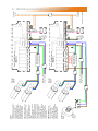
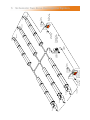
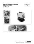
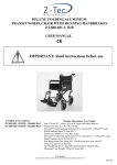
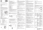
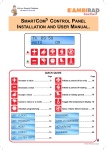
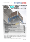
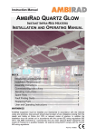
Installation Wiring
SmartCom 3
SMARTCOM 3 CONTROL PANEL &
UNITARY RADIANT / HERRINGBONE.
Section
Wiring Diagrams
Single Zone Unitary Radiant Systems --------------------------------1
Single Zone Herringbone Fan Systems ------------------------------2
Multizone Unitary Radiant Systems ------------------------------------3
Multizone Herringbone Fan Systems ---------------------------------4
Schematic : A Two Zone Herringbone System ---------------------------5
SmartCom³ Commissioning --------------------------------------------------6
Warnings
All external wiring MUST comply with the current IEE wiring regulations.
These instruction MUST be used in conjunction with the SmartCom³ user
manual and the appropriate heater manual.
Visit our Support Database
at www.s-i-d.co.uk
Single Zone Standard Radiant Systems.
SmartCom
Singlezone
NEUT
LIVE
41
40
9
5
6
1/L 2/N
10
B1 B0 B2 S/R0S/R1
(COMMON)
(REMOTE OFF)
NOTES:
(REMOTE ON)
1
REMOTE SENSOR(s) may be placed at a
max distance of 100m from the control unit,
using screened 6A mains* cable.
Wiring should be kept separate from mains
wiring to minimise noise pick up. Set within
Engineers functions for remote sensor.
*The power supply is non-isolated, therefore all
wiring to the control must be mains rated.
Black Bulb
Sensor
eg B.M.S.
REMOTE SWITCH INPUTS should be
connected by 6A mains Max length is 100m.
Low voltage switching inputs to be normally
open (closed circuit to enable).
Connect to B0 & B1 for remote ON (ie BMS
time control).
Connect to B0 & B2 for remote OFF (ie
door interlock. remote frost etc).
*The power supply is non-isolated, therefore all
wiring to the control must be mains rated.
230V 50Hz 1 Pha
Supply via Isolator
Drawing No. : 900295 R4
Note: Connection to the
burners MUST be made
via a 3A fused spur.
2
Single Zone Herringbone Fan Systems.
SmartCom
Singlezone
NEUT
LIVE
41
40
9
5
6
1/L 2/N
10
B1 B0 B2 S/R0S/R1
(COMMON)
*IMPORTANT*
Add this
link wire
(REMOTE OFF)
(REMOTE ON)
NOTES:
REMOTE SENSOR(s) may be placed at a
max distance of 100m from the control unit,
using screened 6A mains* cable.
Wiring should be kept separate from mains
wiring to minimise noise pick up. Set within
Engineers functions for remote sensor.
*The power supply is non-isolated, therefore all
wiring to the control must be mains rated.
Black Bulb
Sensor
eg B.M.S.
REMOTE SWITCH INPUTS should be
connected by 6A mains Max length is 100m.
Low voltage switching inputs to be normally
open (closed circuit to enable).
Connect to B0 & B1 for remote ON (ie BMS
time control).
Connect to B0 & B2 for remote OFF (ie
door interlock. remote frost etc).
*The power supply is non-isolated, therefore all
wiring to the control must be mains rated.
230V 50Hz 1 Pha
Supply via Isolator
L
N
Exhaust
Fan
Drawing No. : 900293 R4
Note: Connection to the
burners MUST be made
via a 3A fused spur.
REMOTE SENSOR(s) may be
placed at a max distance of 100m
from the control unit, using
screened 0.75mm² cable.
Wiring should be kept separate
from mains wiring to minimise noise
pick up. Set within Engineers
functions for remote sensor.
REMOTE SWITCH INPUTS should
be connected by 0.75mm² cable.
Max length is 100m.
Low voltage switching inputs to be
normally open (closed circuit to
enable).
Connect to B0 & B1 for remote ON
(ie BMS time control).
Connect to B0 & B2 for remote OFF
(ie door interlock. remote frost etc).
For Master/Slave networks, remote
OFF can be set for individual zones
or total system via the Master.
If individual BMS ON/OFF on
master/slaves systems are required,
set all SmartCom programs to 24
hour and use normally closed
contacts across B0 and B2. Set
engineers variable.
Burners
Zone A
Burners
Zone B
230V 50Hz 1 Pha
Supply via Isolator
41
230V 50Hz 1 Pha
Supply via Isolator
41
40
40
9
25
14
Note: Connection to the
burners MUST be made
via a 3A fused spur.
8
5
6
7
9
25
14
Note: Connection to the
burners MUST be made
via a 3A fused spur.
8
(Master)
5
6
SmartCom Mulitizone
7
(Slave 1)
SmartCom Mulitizone
NEUT
LIVE
NEUT
LIVE
1/L 2/N
1/L 2/N
10
10
eg B.M.S.
Black Bulb
Sensor
eg B.M.S.
To other slave
controllers
To other slave
controllers
Drawing No. : 900296 R4
S/R0S/R1 D0 D1 O0 O1 B1 B0 B2 C2 C0 C1 66 64 20
Black Bulb
Sensor
S/R0S/R1 D0 D1 O0 O1 B1 B0 B2 C2 C0 C1 66 64 20
(REMOTE ON)
(REMOTE ON)
NETWORK. Master-slave (Network)
communication is by screened
twisted pair cable, RS485
compatible such as Belden 9841.
Maximum overall system length of
500m. Connect screen to C0.
NOTE: Diagram shows a master
and ONE slave configuration**.
Wire further slaves in parallel.
(COMMON)
(COMMON)
NOTES:
(REMOTE OFF)
(REMOTE OFF)
3
Multizone Standard Radiant Systems.
Exhaust
Fan
L
N
REMOTE SENSOR(s) may be
placed at a max distance of 100m
from the control unit, using
screened 0.75mm² cable.
Wiring should be kept separate
from mains wiring to minimise noise
pick up. Set within Engineers
functions for remote sensor.
REMOTE SWITCH INPUTS should
be connected by 0.75mm² cable.
Max length is 100m.
Low voltage switching inputs to be
normally open (closed circuit to
enable).
Connect to B0 & B1 for remote ON
(ie BMS time control).
Connect to B0 & B2 for remote OFF
(ie door interlock. remote frost etc).
For Master/Slave networks, remote
OFF can be set for individual zones
or total system via the Master.
If individual BMS ON/OFF on
master/slaves systems are required,
set all SmartCom programs to 24
hour and use normally closed
contacts across B0 and B2. Set
engineers variable.
230V 50Hz 1 Pha
Supply via Isolator
Burners
Zone A
230V 50Hz 1 Pha
Supply via Isolator
Burners
Zone B
41
41
40
40
9
25
14
Note: Connection to the
burners MUST be made
via a 3A fused spur.
8
5
6
7
9
25
14
Note: Connection to the
burners MUST be made
via a 3A fused spur.
*IMPORTANT*
Add this link wire
8
(Master)
5
6
SmartCom Mulitizone
7
(Slave 1)
SmartCom Mulitizone
NEUT
LIVE
NEUT
LIVE
1/L 2/N
1/L 2/N
10
10
eg B.M.S.
Black Bulb
Sensor
eg B.M.S.
To other slave
controllers
To other slave
controllers
Drawing No. : 900294 R4
S/R0S/R1 D0 D1 O0 O1 B1 B0 B2 C2 C0 C1 66 64 20
Black Bulb
Sensor
S/R0S/R1 D0 D1 O0 O1 B1 B0 B2 C2 C0 C1 66 64 20
(REMOTE ON)
(REMOTE ON)
NETWORK. Master-slave (Network)
communication is by screened
twisted pair cable, RS485
compatible such as Belden 9841.
Maximum overall system length of
500m. Connect screen to C0.
NOTE: Diagram shows a master
and ONE slave configuration**.
Wire further slaves in parallel.
(COMMON)
(COMMON)
NOTES:
(REMOTE OFF)
(REMOTE OFF)
4
Multizone Herringbone Fan Systems.
Isolator
Burner 3
Isolator
Burner 2
Fused Spur
Isolator
Burner 1
230V 50Hz 13A
Mains Supply
SmartCom³ no.1
'MASTER' (SC3-MZ)
Isolator
0.75mm²
Screened
Cable
Sensor
Zone A
1 phase 230V
Exhaust Fan
1 phase
Isolator
Tail Pipe
Burner 3
Isolator
Networking Cable
Screened pair Beldon
9841 or equiv
230V 50Hz 13A
Mains Supply
Isolator
0.75mm²
Screened
Cable
Burner 2
Isolator
SmartCom³ no.2
'SLAVE' (SC3-MZ)
Sensor
Zone B
Burner 1
Isolator
5
Schematic Two Zone Herringbone System
6
SmartCom³ Radiant Commissioning.
For ease and swiftness of initial start-up, the
SmartCom³ range of electronic controllers is
supplied factory pre-set to default settings as
described in the SmartCom³ Installation and
User Manual ref GB/SCOM/120/0309.
The controllers will therefore operate
immediately with standard Warm Air Unit
heaters or Singular Radiant heating systems
without the need for on-site programming.
However, if either multi-zone Radiant, single or
multi-zone Herringbone or single or multi-zone
Nor-Ray-Vac systems are to be operated along
with a Black Bulb Sensor, then the engineers’
settings will have to be modified.
In order to access the engineer functions:
Press and hold in the
button and at the same time, press the
CONTROL TYPE
SET/OK
ARM A I R
press
to alter
or press
to advance
CONTROL TYPE
RAD I ANT
SET/OK
press
to accept.
Press
to advance
RAD/NRV/HB SPL I T
OFF
SET/OK
press
to alter
or press
to advance
RAD/NRV/HB SPL I T
ON
SET/OK
press
to accept.
Press
to advance
I NTERNAL SENSOR
SET/OK
ON
press
to alter
or press
to advance
I NTERNAL SENSOR
SET/OK
OFF
press
to accept.
Press
to advance
EXTERNAL SENSOR
SET/OK
OFF
press
to alter
or press
to advance
EXTERNAL SENSOR
SET/OK
ON
press
to accept.
Press
to advance
NETWORKING
OFF
SET/OK
press
to alter
or press
to advance
NETWORKING
ON
SET/OK
press
to accept.
Press
to advance
MASTER UN I T
OFF
SET/OK
press
to alter
or press
to advance
MASTER UN I T
ON
SET/OK
press
to accept.
Press
to advance
SLAVE UN I T
0
SET/OK
press
to alter
or press
to advance
SLAVE UN I T
3
SET/OK
press
to accept.
Press
to advance
SLAVE TOTAL
0
SET/OK
press
to alter
or press
to advance
SLAVE TOTAL
6
SET/OK
press
to accept.
Press
to advance
M
press
press
once.
once for
split zonal
systems
press
press
press
press
press
press
press
once to
turn off
internal
once to
turn off
external
once for
master
slave
once if
master
unit
for unique
slave
number
for total
no. of
slaves
button.
Notes:
B.
MASTER & SLAVE (NETWORK)
When setting up a SmartCom³ Master and
Slave (Network) system, the master controller
will display an error message during
commissioning.
This will clear once the
commissioning is complete.
Th 09 : 30 Zone 1
COMMS ERR Zone 6
REMOTE SWITCHED INPUTS
Remote Door Interlock
EXTERNAL / DOOR
FROST ONLY
SmartCom³ controllers can be connect to a
door interlock, remote frost stat or permanent
off switch via terminals B2 and B0. When a
volt free connection is provided (ie closed circuit to enable) at these terminals, the
controller reverts to a FROST ONLY mode.
Refer to the individual wiring diagrams for
wiring configurations and type.
SmartCom³ controllers can be operated
remotely via a remote ON or a remote OFF
signal in the following ways:
A. Building Management System Control
(BMS).
EXTERNAL / BMS
AUTO
SmartCom³ controllers can be operated via a
BMS system, by applying a volt free
connection (ie closed circuit to enable) across
terminals B1 and B0 turns the system on.
Making this connection on a master controller
will turn the entire system on whereas making
this connection on a slave unit will only bring
on that zone.
1. BMS Controlling Time only.
Document reference number GB/CON/005/0309
Ensure all the programmed ON times in the
SmartCom³ are turned off
(i.e. They read “- -:- -”).
2. BMS Controlling Time and Temperature.
Ensure all the programmed ON times in the
SmartCom² are turned off
(i.e. They read “- -:- -”). Set all the required
day temperatures to 30°C.
AmbiRad Limited Fens Pool Avenue
Brierley Hill West Midlands DY5 1QA
United Kingdom.
Telephone 01384 489700
Facsimile 01384 489707
Email [email protected]
Website www.ambirad.co.uk
Technical Suport www.s-i-d.co.uk
AmbiRad is a registered trademark of AmbiRad Limited. Because of continuous product
innovation, AmbiRad reserve the right to change product specification without due notice