1
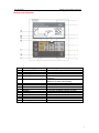
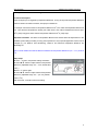
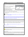
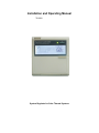
Installation and Operating Manual
TK-SC6
System Regulator for Solar Thermal Systems
Solar Controller
Installation and operation instruction
Display Panel Illustration
Pos.
1
2
3
4
Button on display panel
Green lamp
On/Off
“▲””▼” adjust
T
5
Manual
6
7
8
9
10
11
12
13
14
15
T
OK
C/F
SET
Pipe timing
Recovery
Temp. Display
Clock
Heating
“ →” “←”
LCD display screen
o
Button description
Power indication lamp
Power “switch on/off” button
Adjusting button
To Set switch-on/off temperature difference of solar
circulation
Manual commissioning to trigger temperature
difference controlled solar circulation
Activate/deactivate one function
Celsius / Fahrenheit transformation button
To set time for hot water pipe circulation
To recovery the display to factory set mode.
Display temperature in different position one by one
Clock set
Electrical heating time set
Transfer button
2
Solar Controller
Installation and operation instruction
Content
1. Safety information
1.1 Installation and commissioning
1.2 About this manual
1.3 Liability waiver
1.4 Description of symbols
2. Installation
2.1 Installation of display panel
2.2 Installation of controller
2.2.1 Fixing the hang – panel of controller
2.2.2 Connection of power
• Open/close the cover of terminal panel
• Preparing before connection
• Terminal connection
3. Commissioning
3.1 Time set
3.2 Manual operation
3.3 Temperature query
4. Device setup
4.1 Clock set
4.2 On/Off button operation
4.3 System description
4.4 Temperature difference controlling function
4.5 Temperature controlled auxiliary heating during three time sections
4.6 Time controlled hot water pipe circulation
4.7 Temperature controlled hot water pipe circulation
4.8 Anti freezing protection of collector
4.9 High temperature protection function of tank ( 1)
4.10 High temperature protection function of tank ( 2)
4.11 “oC/F” button
4.12 Auto function
5. Troubleshooting
5.1 Trouble protection
5.2 Error signal indication
5.2 Trouble checking
6. Technical data
3
Solar Controller
Installation and operation instruction
1. Safety information
1.1 Installation and commissioning
• When laying cables, please ensure that no damage occurs to any of the constructional fire safety
measures presented in the building.
• The controller must not be installed in rooms where easily inflammable gas mixtures are present or may
occur.
• The permissible environmental conditions must not be exceeded at the site of installation.
• Before connecting the device, make sure that the energy supply matches the specifications of controller
• All devices connected to the controller must conform to the technical specifications of the controller.
• All operations on an open regulator are only to be conducted cleared from the power supply. All safety
regulations for working on the power supply are valid. Connecting and /or all operations that require
opening the regulator (e.g. changing the fuse) are only to be conducted by specialists.
1.2 About this manual
This manual describes the installation, function and operation of a solar thermal controller.
When installing the remaining components e.g. the solar collectors, pump assemblies and the storage unit,
be sure to observe the appropriate installation instructions provided by each manufacturer. Installation,
electrical connection, commissioning and maintenance of the device may only be performed by trained
professional personnel. The professional personnel must be familiar with this manual and follow the
instructions contained herein.
1.3 Liability waiver
The manufacturer cannot monitor the compliance with these instructions or the circumstances and
methods used for installation, operation, utilization and maintenance of this controller. Improper installation
can cause damages to material and persons. This is the reason why we do not take over responsibility and
liability for losses, damages or cost that might arise due to improper installation, operation or wrong
utilization and maintenance or that occurs in some connection with the aforementioned. The manufacturer
preserves the right to put changes to product, technical date or installation and operation instructions
without prior notice. As soon as it becomes evident that safe operation is no longer possible (e.g visible
damage). Please immediate take the device out of operation.
Note: ensure that the device cannot be accidentally placed into operation.
1.4 Description of symbols
Safety instruction:
Safety instructions in the text are marked with a yellow warning triangle. They indicate measures,
which can lead to injury of persons or safety risks.
Operation steps: small triangle “►”is used to indicate operation step.
Note: contains important information for operation or function, it is written in blue color
4
Solar Controller
Installation and operation instruction
2. Installation
2.1 Installation of display panel
►Remove the back panel from display with screw in direction showed on picture 1
►Fix the back panel with screw on the wall, please note don’t drill hole on controller, see picture 2
►Insert the upper case of display into the grooves
of back panel, fasten them, see picture 3
Fixing hole
Picture 1
Picture 2
Picture 3
2.2 Installation of controller
Note:
: Controller must only be installed in a place
having an adequate level of protection.
2.2.1 Fixing the hang – panel of controller
► selecting a proper place
► putting hang-panel on wall and marking the position of hole
(note the up/down side of panel) see picture 4
► drilling-hole and put the plastic expansion screw in it
► Screw hang-panel
► hanging the controller on this panel reliably
2.2.2 Connection of power
Picture 4
Remove the device from the mains supply before opening the case! All guidelines and regulations of
the local electricity supplier must be observed
• Open and close the cover of terminal panel
► Loosen the screw
and remove the upper case in an upwards
direction, see picture 5
► Close the cover : downwards close the cover
► fasten with screw
Picture 5
5
Solar Controller
Installation and operation instruction
• Preparation before connection
Power can only be switched on when the
housing of controller is closed, an installer
must make sure that the IP protection class of
the
controller
is
not
damaged
during
installation.
Depending on the type of installation, the
cables may enter the device through the rear
of the case
or through the lower side of the
case. See picture 6
Cable comes from the rear
: remove the
plastic flaps from the rear side of the case
using an appropriate tool.
Cable comes from the below: cut the left
Picture 6
and right plastic flaps using an appropriate tool
(e.g. knife) and break them out of the case.
After connection the cable, please put the cable into groove and fix them by cable press plate.
• Terminals connection ( see picture 7)
Picture 7
Abbreviation
T1
T2
T3
T4
No:01
Power
Heating
Ton/ Toff
Pipe circuit
Function
Input port of collector temperature sensor T1
Input port of tank temperature sensor T2, bottom
Input port of tank temperature sensor T3, above
Input port of hot water pipe temperature sensor, optional
Connection port for display panel
Power input port
Output port of electrical heating H1
Output port of temperature difference circulation pump P1
Output port of hot water pipe circulation pump P2
6
Solar Controller
Installation and operation instruction
Input ports
Output ports
Power connection
1. Inputs T1, T2 and T3
1. Outputs P1 and P2:
1. Please note the type of power
(T4 optional): are
electromagnetic relays
supply required from the type
temperature sensors.
max. Switching current: 5A
label on the case of the
2. Inputs No:01 is 3-core
wire connected with
2. Output H1: electromagnetic relay,
max switching current 16A.
display.
device
2. The protective conducting
wire (earth wire) must also be
connected
Reset: This button is on the terminal connection panel, when system program is out of working, press
“Reset” to recover the program of system to the factory settings.
Advice regarding the installation of temperature sensors:
Only original factory equipped Pt1000 temperature sensors are approved for use with the collector, it is
equipped with 1.5meter silicon cable and suitable for all weather conditions, the temperature sensor and
cable are temperature resistant up to 280oC, not necessary to distinguish the positive and negative polarity
of the sensor connection.
Only original factory equipped NTC10K,B=3950 temperature sensors are approved for use with tank and
pipe, it is equipped with 1.5meter PVC cable, and they are temperature resistant up to 105oC, not
necessary to distinguish the positive and negative polarity of the sensor connection.
All sensor cables carry low voltage, and to avoid inductive effects, must not be laid close to 230 volt or
400-volt cables (minimum separation of 100mm)
If external inductive effects are existed, e.g. from heavy current cables, overhead train cables, transformer
substations, radio and television devices, amateur radio stations, microwave devices etc, then the cables
to the sensors must be adequately shielded.
Sensor cables may be extended to a maximum length of ca. 100 meter, when cable’s length is up to 50m,
2
2
and then 0.75mm cable should be used. When cable’s length is up to 100m, and then 1.5mm cable
should be used.
Note: PT1000 and NTC10K, B=3950 are different kind of temperature sensor, it may exist measuring error
between these twos at the same ambient temperature, but it doesn’t effect the operation of system.
3. Commissioning
Connect the sensors, pumps to the controller before you connect the power supply!
After switching on power to the controller, firstly controller will ask to set “clock”
3.1 Time set
After power is switched on, “00:00” displays on LCD screen.
► Press “Clock” button, hour selection area “00” blinks on display screen.
► Press “▲”“▼” button to adjust hour of clock
► Press “Clock” button again, the minute selection area “00” blinks
► Press “▲”“▼” button to adjust minute of clock
After 6 seconds controller confirms the setting automatically, the current time is displayed on the screen.
7
Solar Controller
Installation and operation instruction
3.2 Manual operation
When operating the device first time, or when testing the function, the outputs of controller can be operated
manually. To do like the following steps:
• Temperature difference controlled pump operated manually
►Press “ Manual
T” button, temperature difference controlled solar circulation pump is triggered
immediately, the relevant signal is lighted.
►Press ““Manual
T ” button again to shut off this output immediately, or program switches off the pump
in 10 minutes automatically.
• Hot water pipe circulation pump operated manually
► In the status that power is on, press “On/Off ” button, the hot water pipe circulation pump is triggered
immediately, The relevant signal is lighted.
► Press “On/Off ” button again to shut-off this operation, or program stops pump in 3 minutes
automatically.
• Heating operated manually
►Press “Heating ” button for 6 seconds, the auxiliary electricity heating or gas, oil boiler is triggered.
►Press “Heating” button again to shut off this output immediately.
3.3 Temperature query
►Press “Temp. Display” button to check different temperature value of collector (T1), tank (bottom T2),
tank (above T3) and hot water pipe circulation (T4) one by one. Temperature of bottom tank (T3) is
displayed automatically when no more operation within 6 seconds.
4. Device setup
4.1Clock set
► Press “Clock” button, the hour selection area “00” blinks on display screen.
► Press “▲”“▼” button to adjust hour of clock
► Press “Clock” button again, the minute selection area “00” blinks
► Press “▲”“▼” button to adjust minute of clock
After 6 seconds controller confirms the setting automatically, the current time is displayed on the screen
4.2 On/Off button operation
After power is switched-on, as default set controller is in open status, it displays water temperature of tank
and clock time, all functional buttons are ready for setting operational parameters.
► Press “On/Off ” button, 3 minutes water circulation function becomes into affect (hot water pipe
circulation pump), circulation signal is indicated on screen, 3 minutes later program stops water circulation
pump automatically.
► Press “On/Off ” button for 3 seconds, controller is closed, only tank temperature and time are displayed
on screen. In the status that controller is closed, press this button again, controller reopened.
8
Solar Controller
Installation and operation instruction
4.3 System description
4.3.1
1 collector array – 1 storage tank – 1 pump ( 1 sensor on tank)
Description:
The solar circuit pump (P1) is triggered immediately when
the switch-on temperature difference between the
collector array (T1) and the storage tank (T2) is reached.
When the temperature difference between the collector
array (T1) and storage tank (T2) drops below the
switch-off temperature difference, then the solar circuit
pump ( P1) is ceased.
T1: Temperature sensor for collector
T2: Temperature sensor in the bottom part of tank (for
controlling temperature difference circulation and
auxiliary heating).
P1: Temperature difference solar circuit pump
P2: Hot water circuit pump
Note:
H1 is port for connecting with auxiliary electrical heating
booster,
T4: is temperature sensor positioned on the pipe of user
side.
4.3.2 1 collector array – 1 storage tank – 1 pump (2 sensors on tank)
Description:
The solar circuit pump (P1) is triggered when the
switch-on temperature difference between the collector
array (T1) and the storage tank (T2) is reached. when the
temperature difference between the collector array (T1)
and storage tank (T2) drops below the switch-off
temperature difference, then the solar circuit pump ( P1)
is ceased.
T1: Temperature sensor for collector
T2: Temperature sensor in the bottom part of tank (for
temperature difference circulation).
T3: Temperature sensor in the top part of tank (for
auxiliary heating).
P1: Temperature difference solar circuit pump 1
P2: Hot water circuit pump
Note:
• H1 is port for connecting with auxiliary electrical
heating booster,
• T4 is temperature sensor positioned on the pipe of
user side.
• When the sensor T3 (in top part of tank) is damaged,
controller will adopt the signal from sensor T2 (in
bottom part of tank) to control the electrical heater.
9
Solar Controller
Installation and operation instruction
4.4 Temperature difference controlling function
Functional description:
Solar circuit pump P1 is triggered by temperature difference, so long as the preset temperature difference
between collector and tank is reached, solar pump is switched on.
For example: if we set the switch-on temperature difference is 8 oC, the switch-off temperature difference is
4oC. Then when the temperature in bottom part of tank is 20oC, the collector temperature must rise up to
28oC, pump is triggered, when collector temperature falls below 24oC, pump stops.
Important information: the switch-on temperature difference 8oC and the switch-off temperature 4oC are
standard system setting according to many years’ experiences. Only in special application cases it can be
changed (e.g. far distance heat transferring), switch-on and switch-off temperature difference are
alternating set.
Note: to avoid mistake the minimum difference between two temperature differences (∆Ton - ∆Toff ) is set as
2oC.
Setup steps:
► Press “ T” button, temperature setting area blinks.
► Press“▲”“▼” button to adjust switch-on temperature
difference. (Adjustable range: 2oC ~ 15oC, default valve
is 8oC.)
►Press “ T” button again.
► Press“▲”“▼” button to adjust switch-off temperature
difference. (Adjustable range: 0oC ~ (on- 2oC), default
valve is 4oC.)
After 6 seconds, controller confirms the setting.
10
Solar Controller
Installation and operation instruction
4.5 Temperature controlled auxiliary heating during three time sections
Functional description:
Solar system can be combined with electrical booster or gas, oil boiler; controller can achieve automatically
temperature and time controlled heating. During the preset time sections electrical booster is triggered
o
when the temperature (T3) of top part of tank is 6 C below the preset switching-off temperature of electrical
booster. When T3 exceeds or equals the preset temperature, electrical booster stops heating.
Note:
When it is outside of the preset time section, electrical booster doesn’t work automatically even when the
tank temperature reaches the start temperature of electrical heating.
Setup steps:
► Press “Heating” button, timing area blinks on display, you can set turning on time and temperature of
electrical heating now,
► Press “▲”“▼” button to set hour,
► Press“←”、“→” button to shift to minute setting,
► Press “▲”“▼” to set minute.
► Press “←”、“→”again to shift to temperature area,
► Press “▲”“▼” to set turning off temperature of electrical
heating.
► Press “Heating” button again, you can set turning off time
of electrical heating.
► Press “▲”“▼” button to set hour.
► Press“←”、“→” button to shift to minute setting.
► Press “▲”“▼” to set minute.
• 6 seconds later controller confirms the settings
• Doing like above described steps, three timing sections can be set. ( 1-3 displays on screen to indicate
the preset time section)
• Default setting:
First heating time section: 4:00 turning on, 5:00 turning off
Second heating time section: electrical heater doesn’t work, setting is 10:00 ~10:00
Third heating time section: 17:00 turning on, 22:00 turning off
o
Default turning off temperature of electrical booster is 55 C.
• If you want to shut off heating in one time section, then you can set the turning on time and turning off
time same value (for example, the second time section no this function, then you can set turning on time
is 10:00, turning off time is 10:00 also).
• Controller has memory function, your setting is remembered, and you don’t need to set everyday.
• Pressing “Heating” button can check the setting.
Manual operation:
►Press “Heating” button for three seconds, electrical heater is triggered immediately, the corresponding
signal is lighted,
►Press “Heating” button again, electrical booster switches off immediately.
Note: when heating signal displays on screen, it means this function is in operation.
Gives an example:
1.when no temperature sensor (T3) is installed in the top part of tank or T3 is damaged, controller will take
the signal from bottom temperature sensor (T2) automatically and control auxiliary heating function.
2.within one time section of the timing heating, press “ Heating “ button to exit the timing heating function of
this time section.
3. Preset switch-off time of timing heating should be later than the switch-on time of timing heating
For example: if you set the switch-on time of timing heating is 17:00 and set switch-off time is 06:00, then
heating in this time section is ineffective; the right setting is like following:
11
Solar Controller
Installation and operation instruction
This setting should be divided into two time sections, the first time section is from 17:00 to 23:59, then second
time section is from 00:00 to 06:00.
4.The set switch-on time of heating should be later than the current clock’s time, otherwise the setting can not
effect in this day. If you set the switch-on time is earlier than the current clock’s time, then the heating will be
effective in next day.
For example: if the current clock’s time is 8:00 am and you set the switch-on time of heating is 7:00, switch-off
time is 9:00, then heating in current day is ineffective , time heating function will start from next day.
4.6 Time controlled hot water pipe circulation
Functional description:
Solar system can provide time-controlled hot water pipe circulation function; through this function can
realize to get hot water immediately when man opens the tap. This function needs an extra circulation
pump (P2), and this pump can be triggered automatically within the preset time section. Within the preset
time section pump (P2) operates for three minutes, and then stops for 15 minutes, after then it triggers
again for 3 minutes, stops for 15 minutes, same process continues so. Three time sections can be set
within one day.
Setup steps:
►Press “Pipe timing” button, timing setting area blinks, to
set the start time of circulation.
►Press “▲”“▼” button to adjust hour
►Press “←”、“→” transfer button to minute area
► Press “▲”“▼” button to adjust minute
► Press “Pipe timing” button again to set the end time of circulation
► Press “▲”“▼” button to adjust hour
►Press “←”、“→” transfer button to minute area
► Press “▲”“▼” button to adjust minute
• After 6 seconds, controller confirms setting automatically
• Doing like above steps. Within one day, three time sections can be set ( 1-3 displays on screen to indicate
the preset time section)
• If you want to shut off one timing circulation, then you can set the turning on time and turning off time
same value (for example, deactivate the function in the second time section, then you can set turning on
time is 10:00, and then set turning-off time is 10:00 also)
• Controller has memory function, setting is remembered, it needn’t to set everyday. Everyday when the
preset time is coming, water circuit pump is triggered automatically.
• Pressing “Pipe timing” button can check the setting.
Manual operation: At the status that controller is in operation, hot water circuit pump can be triggered
immediately by pressing “On/Off” button, pipe circulation signal displays. If the time of this operation is
happened at the preset time section, it works as normal situation, namely works for 3 minutes, then stops
for 15 minutes, same process continues within the time section. If the time of this operation is not within the
preset time section, it works for 3 minutes, and then it stops automatically, no more restart.
At the status that hot water circuit pump is in operation, press “Pipe timing” again to stop pump
immediately.
12
Solar Controller
Installation and operation instruction
4.7 Temperature-controlled hot water circuit pump
Note: T4 sensor isn’t included in the standard delivered product; user needs to have a extra temperature
sensor T4 when he wants to have this function.
Functional description:
Solar system can provide temperature-controlled hot water circulation function, this function needs an
extra hot water circulation pump ( P2) and a sensor (T4), which is positioned on the return pipe of hot
water . When the temperature signal of sensor T4 is less than the preset turning on temperature, the hot
water circulation pump (P2) is triggered and works till the temperature exceeds the turning off temperature.
o
o
If the preset turning-on temperature of this function is 40 C, then when T4 is less than 40 C, for example it
o
is 39 C, this circulation pump is triggered and it is ceased
o
until T4 temperature reaches 45 C.
Activate/deactivate this function:
►Press “SET” button 2 times, the hot water circulation
temperature setting area blinks, default setting is “OFF”
mode, “----”displays.
► Press “OK” button to activate this function.
► Press“▲”“▼” button to adjust the temperature of circulation pump, (adjustable range: 20oC –50oC), after
6 seconds, controller confirms the setting automatically.
►In the status of setting the temperature for circulation pump, press “OK” button to deactivate this function,
“ -----“ displays.
Note:
• Temperature –controlled hot water circulation function is priority to trigger than time-controlled hot water
circulation function.
• If the temperature-controlled hot water circulation function is triggered, then time-controlled hot water
circulation function is ceased automatically.
• If the temperature-controlled hot water circulation function is ceased, then time-controlled hot water
circulation function is triggered automatically.
• The position of the sensor T4 should be minimum 1.5m far from tank, so that avoid the measuring error.
4.8 Anti freezing protection of collector
Note: this function is only useful in the system, which doesn’t use anti-freezing liquid.
Functional description:
o
In Winter when the temperature of collector is below the preset start temperature (2-10 C) of anti-freezing
protection, solar circuit pump is triggered. While the anti-freezing protection function works, if the tank
13
Solar Controller
Installation and operation instruction
temperature is less than 10oC, electrical booster will be triggered immediately and is switched off until
water up to 15oC or when frost protection function is deactivated. When temperature of collector is 5oC
higher than preset start temperature of frost protection, controller stops solar circuit pump and exits the
program.
This function is used in the system which uses water as
heat transfer medium to avoid freezing problem.
Activate/deactivate this function:
►Press “SET ” button 1 time, the frost protection setting
area blinks; default setting is off, display “----“.
►Press “OK” button to activate this function.
►Press“▲”“▼” button to adjust the switch-on temperature of frost protection, (adjustable range: 2oC
–10oC), after 6 seconds, controller confirms the setting automatically.
►In the status of setting frost protection temperature, press “OK” button to cease this function,
“----“ appears on screen.
When the signal of frost protection displays on screen, it indicates frost protection
function is activated.
Note: this function is allowed to be used in the solar system, which doesn’t use anti-freezing heat transfer
liquid, in the area where only few days in whole year the ambient temperature may be closed to the
freezing temperature. But for a safety system and in the area where anti-freezing must be considered, we
suggest using proper anti-freezing liquid to resolve freezing problem.
4.9 tank high temperature protection ( 1)
In order to avoid the high temperature of tank, controller will check the temperature of bottom part of tank
o
(T2), when T2 rises to 95 C,this function is activated, and solar pump is ceased. When temperature of
o
bottom part of tank (T2) drops less than 85 C, this function is deactivated automatically.
When the signal of high temperature protection (1) displays on screen, it indicates
this function is activated.
Note: this function is a default design; its parameters can’t be set.
4.10 tank high temperature protection ( 2)
Note: this function is only useful in the solar system, which uses tank with two heat exchangers.
(Default setting of this function is closed).
Functional description:
It needs an extra valve on the inlet pipe, in order to avoid the high temperature of tank, controller will check
the temperature of bottom part of tank (T2), if T2 is higher than the preset switching-on temperature of this
function, this extra valve will be opened. When T2 drops 5oC below the switching-on temperature of this
function, the extra valve will be closed automatically.
14
Solar Controller
Installation and operation instruction
Activate /deactivate this function:
►Press “SET” button 3 times, maximal tank temperature setting area blinks; default setting is off, display
“----“.
►Press “OK” button to activate this function.
►Press“▲”“▼”
button
to
adjust
the
maximum
o
temperature of tank, (adjustable range: 80 C –99oC),
after 6 seconds, controller confirms the setting
automatically.
►In the status of setting maximal temperature of tank,
press “OK” button to cease this function, “----“appears on screen.
When the signal of high temperature protection (2) displays on screen, it indicates this function is
activated.
o
4.11 “ C/F” button
o
►Press “ C/F” button to achieve display of temperature between Celsius and Fahrenheit.
4.12 Protection function
a.Memory protection when power is failure
In case power failure occurs, controller keeps the parameter settings unchanged.
b.Anti-bacteria protection
In order not to effect the health of customer and to prevent to occur bacteria when tank temperature is
lower for a long time, controller will check the temperature of tank every 7 days in a period automatically, if
the temperature of tank is never over 70℃ during the period, then at the default time of 23:00 on the
seventh day of the period auxiliary heating system is triggered automatically, when the temperature rises
to 70℃, the auxiliary heating stops, bacteria is killed.
C.Screen protection
When no any press on button for 60 minutes, screen protection is activated, and then LED light lamp is
switched-off. Through press any button to light LED lamp again.
d.. System comeback
When mistakes or problems occur in system, press “OK” button, which is on display panel, to recover
system to factory set.
5. Trouble shooting
5.1 Trouble protection
When there is a break or short circuit between the connection of temperature sensors, controller switches
off the corresponding functions and no more output signals are given, at the same time error indications are
showed on the display.
5.2 Error messages indication
15
Solar Controller
Installation and operation instruction
If control unit does not work correctly, please check following error messages and error rectification
indication. “Warning “signal is displayed on screen.
Error messages and handling indication (LCD display warning signal blinks)
Error
Meaning
Cause of error
message
T1
T1 sensor fault
Sensor wiring interrupted, not
connected or short circuit
blinks
T2
T2 sensor fault
Sensor wiring interrupted, not
connected or short circuit
blinks
o
T3 99 C
T3 sensor fault
Sensor wiring interrupted, not
blinks
connected or short circuit
E0
Connection fault between display
and controller
Error rectification
Connection cable is interrupted or
short circuit
Check
resistance
value, replace sensor if
necessary
Check
resistance
value, replace sensor if
necessary
Check
resistance
value, replace sensor if
necessary
Check and replace if
necessary
Note: when the error of sensor appears, its corresponding function will be switched off automatically.
5.3 Error checking
The controller is quality product, conceived for years of continuous trouble-free operation. If a problem
occurs, the cause of the problem very often lies not in the controller but in the peripheral components. The
following description of some well-known problems should help the installer and operator to isolate the
problem, so that the system can be place back into operation as quickly as possible and to avoid
unnecessary costs. Of course, not all possible problems can be listed here. However, most of the normal
problems encountered with the controller can be found in the list below, only return the controller when you
are absolutely sure that none of the problems listed below is responsible for the fault.
a. A potentially defective sensor can be checked using an ohmmeter. To do this, the sensor must be
disconnected, its resistance measured, and the value compared with the figures in the table below, small
deviation are acceptable, (note: remove the device from the mains supply before opening the case)
PT1000 resistance value
oC
0
10
20
30
40
50
60
70
80
90
100
110
120
Ω
1000
1039
1077
1116
1155
1194
1232
1270
1309
1347
1385
1422
1460
NTC 10K B=3950 resistance value
oC
0
10
20
30
40
50
60
70
80
90
100
110
120
Ω
33620
20174
12535
8037
5301
3588
2486
1759
1270
933
697
529
407
b. Cause of failures
Symptoms
Secondary symptoms
Possible cause
Procedure
Controller does not
Display shows nothing,
Controller power supply
Check the controller
appear to function at all
no display illumination
is interrupted
power cable and
connection cable
between controller and
display.
The solar pump doesn’t
The pump symbol in the
Pump power supply is
Check the pump power
operate, despite the fact
display blinks
interrupted
cable
that switch-on
conditions are satisfied
16
Solar Controller
Pump doesn’t operate
Installation and operation instruction
The pump symbol in the
Fault ( short circuit or
On the controller,
display doesn’t blink,
open circuit) in a
request the current
error message signal
temperature sensor
values from all
blinks on the display
connected temperature
screen.
sensors, replace all
defective sensors and
/or cabling
The solar pumps
The pump symbol in the
The frost protection
No problem, it is normal.
operated, despite the
display blinks.
function is activated.
If necessary to
fact that the switch-on
deactivate the
conditions are not
corresponding functions.
satisfied.
C. Guarantee
The warranty expires within 24 months after the date of purchasing the controller.
6. Technical data
Appearance of display see product itself (dimension: 120mm x120mm x18mm)
Appearance of controller: see product itself (dimension: 200mm x140m x 45mm)
Power supply:AC220V ±10%
Power consumption:< 3W
o
Accuracy of temperature measuring: ± 2 C
Range of temperature measuring: 0 ~120 oC
Suitable power of pump: 2 pumps possible to be connected, power of each pump < 600W
Suitable power of valve: 1 valve possible to be connected, possible power < 600W
Suitable power of electrical booster:standard ≤ 2000W,
Inputs: 4 sensors,
1 Pt1000 sensor (≤500oC) for collector (silicon cable≤280oC),
1 or 2 NTC10K, B3950 sensor (≤ 135oC) for tank, (PVC cable ≤105oC),
o
o
1 NTC 10K, B3950 sensor (≤ 135 C) for hot water circuit pump. (PVC cable ≤105 C),
Note: sensor for hot water circuit pump is optional.
• Outputs:4 relays, one for electrical booster, 2 for circulation pumps, 1 for valve.
• Ambient temperature :-10oC ~ 50oC.
• Water proof grade:IP40.
•
•
•
•
•
•
•
•
•
•
• Socket : Choice by customer (Europe, American, Chinese or others, please note in order)
17