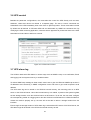
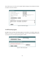
1
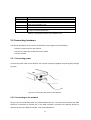
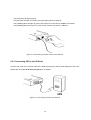
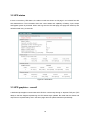
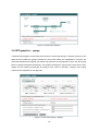
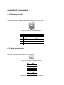
UPS Web/SNMP Card UPSLink User Guide Version 2.2.3 2007-05-07 1 User Guide for the UPSLink Version 2.2.3 Firmware version 2.2.x Printed in Korea Copyright Information Copyright 2002-2007, Sena Technologies, Inc. All rights reserved. Sena Technologies reserves the right to make any changes and improvements to its product without providing prior notice. Trademark Information HelloDevice™ and UPSLink™ are trademarks of Sena Technologies, Inc. Windows® is a registered trademark of Microsoft Corporation. Ethernet® is a registered trademark of XEROX Corporation. Notice to Users Proper back-up systems and necessary safety devices should be utilized to protect against injury, death or property damage due to system failure. Such protection is the responsibility of the user. This device is not approved for use as a life-support or medical system. Any changes or modifications made to this device without the explicit approval or consent of Sena Technologies will void Sena Technologies of any liability or responsibility of injury or loss caused by any malfunction. Technical Support Sena Technologies, Inc. 210 Yangjae-dong, Seocho-gu Seoul 137-130, Korea Tel: (+82-2) 573-5422 Fax: (+82-2) 573-7710 E-Mail: [email protected] Website: http://www.sena.com 2 Revision history Date Part number Description 2003-04-30 V2.0.0 written by UIS 2003-05-02 V2.0.1 revise candidate by KCY, 2003-05-13 V2.0.2 revised done by KCY 2003-05-26 V2.1.1 revised by UIS with firmware upgrade to 2.1.0 2003-07-09 V2.2.1 revised by UIS 2005-11-08 V2.2.2 Temperature and Humidity update 2007-05-07 V2.2.3 Warranty added 3 Contents 1. Introduction 6 1.1 Overview................................................................................................................................6 1.2 Package check list ................................................................................................................. 7 1.3 Product specification ..............................................................................................................7 1.4 Terminologies and acronyms .................................................................................................. 8 2. Getting Started 10 2.1 Panel layout ......................................................................................................................... 10 2.1.1 UPSLink panel layout ................................................................................................. 10 2.2 Connecting hardware ........................................................................................................... 11 2.2.1 Connecting power ...................................................................................................... 11 2.2.2 Connecting to the network .......................................................................................... 11 2.2.3 Connecting UPS to the UPSLink................................................................................. 12 2.3 Accessing the UPSLink ........................................................................................................ 13 2.3.1 Using system console................................................................................................. 13 2.3.2 Using Telnet............................................................................................................... 14 2.4 Accessing web Interface ....................................................................................................... 15 3. UPS management 17 3.1 UPS information ................................................................................................................... 17 3.2 UPS status ........................................................................................................................... 18 3.3 UPS graphics – overall ......................................................................................................... 18 3.4 UPS graphics – gauge.......................................................................................................... 19 3.5 UPS configuration ................................................................................................................ 20 3.6 UPS control.......................................................................................................................... 21 3.7 UPS alarm log...................................................................................................................... 21 3.8 UPS serial program .............................................................................................................. 22 4. Network configuration 23 4.1 IP configuration .................................................................................................................... 23 4.1.1 Using static IP address ............................................................................................... 24 4.1.2 Using DHCP............................................................................................................... 25 4.1.3 Using PPPoE ............................................................................................................. 26 4.2 SNMP configurations............................................................................................................ 26 4.2.1 MIB-II system objects configuration ............................................................................ 27 4.2.2 Access control configuration ....................................................................................... 28 4.2.3 Trap receiver configuration ......................................................................................... 28 4.2.4 Management using SNMP .......................................................................................... 29 4.3 Dynamic DNS configuration.................................................................................................. 29 4 4.4 SMTP configuration.............................................................................................................. 30 4.5 Access control...................................................................................................................... 31 4.6 SYSLOG server configuration............................................................................................... 32 4.7 NFS server configuration...................................................................................................... 33 4.8 Ethernet configuration .......................................................................................................... 34 5. Serial port configuration 35 5.1 UART configuration .............................................................................................................. 35 6. System status and log 36 6.1 System status ...................................................................................................................... 36 6.2 System log configuration ...................................................................................................... 36 7. System administration 38 7.1 User administration .............................................................................................................. 38 7.2 Device name configuration ................................................................................................... 40 7.3 Language............................................................................................................................. 41 7.4 Date and time settings.......................................................................................................... 41 7.5 Factory default reset............................................................................................................. 42 7.6 Firmware upgrade ................................................................................................................ 42 Appendix A. Connections 45 A.1 Ethernet pin outs.................................................................................................................. 45 A.2 Serial port pin outs............................................................................................................... 45 A.3 Ethernet wiring diagram ....................................................................................................... 46 A.4 Serial wiring diagram ........................................................................................................... 46 Appendix B. Well-known port numbers Appendix C. Guide to the Bootloader menu program 47 48 C.1 Overview ............................................................................................................................. 48 C.2 Main menu........................................................................................................................... 48 C.3 Hardware test menu ............................................................................................................ 48 C.4 Firmware upgrade menu...................................................................................................... 51 Appendix D. Warranty 53 D.1 GENERAL WARRANTY POLICY ......................................................................................... 53 D.2 LIMITATION OF LIABILITY .................................................................................................. 53 D.3 HARDWARE PRODUCT WARRANTY DETAILS.................................................................. 54 D.4 SOFTWARE PRODUCT WARRANTY DETAILS .................................................................. 54 D.5 THIRD-PARTY SOFTWARE PRODUCT WARRANTY DETAILS .......................................... 54 5 1. Introduction 1.1 Overview The UPSLink is an embedded Linux-based Web/SNMP card for UPS. The UPSLink provides SNMP, HTTP and Telnet compatibility allowing those who manage power utilities of any equipments that demand fail-safe power such as servers, routers and other networking devices to monitor and control their equipments anywhere on the network. Integrative standard By utilizing standard MIB (Management Information Base), cooperative management of UPS with any management software such as HP OpenView, Sun NetManager and IBM NetView is enabled. The UPSLink fully complies with RFC1628 Industry standard UPS MIB to achiev e comprehensive remote UPS management Easy style web menu The web menus of the UPSLink are well organized and stylish. The graphical presentation of the UPS status helps users to perceive the situation at a glance. Also, rich java script tools are supported to avoid users’mal-operation in each page. Secure management The UPSLink has many features regarding secure management of the device like as user ID and Password authentication, configurable access control for Web or Telnet by IP filtering and HTTPS. Roomy customizability User may customize RS232 UPS protocol and web menus. Sena provides extensive protocol customization tool that includes library functions, template codes, and a complete example for Sena UPS serial protocol and fine manuals. The UPSLink is multilingual on its web interface. The UPSLink is ready to support any languages on earth. Network connectivity The UPSLink supports open network protocols such as TCP/IP, UDP and PPPoE (PPP-over-Ethernet), allowing simultaneous equipment management over either a DSL-based broadband Internet connection, or a conventional LAN (Local Area Network) environment. In-Band management is provided using a 10/100 Base-TX Ethernet network, whereas the Out-of-Band management is done via broadband access. A separate protocol is provided for floating IP environments (Broadband or Dynamic DNS) to allow access to the UPSLink via a domain name. 6 1.2 Package check list UPSLink100: - 110~230 VDC power adaptor - Serial console cable - CD-ROM, including software and manuals 1.3 Product specification UPS Smart UPS with serial data port 3-phase UPS support User customizable serial protocol and behavior Real time delivery of UPS alarm via SNMP trap, SNMP notification and Email Monitor and control the UPS via SNMP, Web and Telnet RFC 1628 UPS-MIB fully compliant Serial interfaces RS232 with DB9 female connector Serial speeds 1200bps to 230Kbps Flow Control: None, Hardware RTS/CTS, Software Xon/Xoff Signals: RS232 Rx, Tx, RTS, CTS, DTR, DSR, DCD, GND Network Interface Diagnostic LED 10/100 Base Ethernet with RJ45 Ethernet connector Supports static and dynamic IP address Power Ready Serial Rx/Tx for serial port 10/100 Base, Link, Act for LAN port Protocols ARP, IP/ICMP, TCP, Telnet, DNS, Dynamic DNS, HTTP, HTTPS, SMTP, SMTP with Authentication, pop-before SMTP, DHCP client, NTP, PPPoE, SNMP v1 & v2c MIB MIB II (RFC 1213) UPS MIB (RFC 1628) User ID & Password Security User-level control with discriminated privileges HTTPS IP address filtering User customizability Serial protocol Web menu Language (upon request) Management Serial console port, Telnet, Web, HelloDevice Manager, SNMP System logging Automatic email delivery of system log To RAM disk or NFS server or syslog server System statistics Full-featured system status display Firmware Downloadable via Telnet , serial console or Web interface 7 Environmental Power Dimension LxWxH Weight (g) Certification Warranty o Operating temperature: 0 ~ 50 C Storage temperature: -20 ~ 66 o C Humidity: 90% Non-condensing 5VDC, 1.5A @ 5V 100 x 72 x 25 (mm) 3.9 x 1.8 x 1.0 (in.) 240 FCC, CE, MIC 5-year limited warranty 1.4 Terminologies and acronyms This section will define commonly used terms in this manual. These terms are related to networking, and defined in regards to their use with UPSLink. MAC address On a local area network or other network, the MAC (Media Access Control) address is the computer's unique hardware number. (On an Ethernet LAN, it is the same as the Ethernet address.) It is a unique 12-digit hardware number, which is composed of 6-digit OUI (Organization Unique Identifier) number and 6-digit hardware identifier number. The UPSLink has the following MAC address template: 00-01-95-xx-xx-xx. The MAC address can be found on the bottom of the original package. Host A user’s computer connected to the network Internet protocol specifications define "host" as any computer that has full two-way access to other computers on the Internet. A host will have a specific "local” or “host number" that, together with the network number, forms its unique IP address. Session A series of interactions between two communication end points that occur during the span of a single connection Typically, one end point requests a connection with another specified end point. If that end point replies, agreeing to the connection, the end points take turns exchanging commands and data ("talking to each other"). The session begins when the connection is established at both ends and terminates when the connection is ended. 8 ISP Internet Service Provider PC Personal Computer NIC Network Interface Card MAC Media Access Control LAN Local Area Network UTP Unshielded Twisted Pair ADSL Asymmetric Digital Subscriber Line ARP Address Resolution Protocol IP Internet Protocol ICMP Internet Control Message Protocol UDP User Datagram Protocol TCP Transmission Control Protocol DHCP Dynamic Host Configuration Protocol SMTP Simple Mail Transfer Protocol FTP File Transfer Protocol PPP Point-To-Point Protocol PPPoE Point-To-Point Protocol over Ethernet HTTP HyperText Transfer Protocol DNS Domain Name Service DDNS Dynamic Domain Name Service SNMP Simple Network Management Protocol NTP Network Time Protocol UART Universal Asynchronous Receiver/Transmitter Bps Bits per second (baud rate) CTS Clear to Send DSR Data Set Ready DTR Data Terminal Ready RTS Request To Send Table 0-1 Acronym Table 9 2. Getting Started This chapter describes how to set up and configure the UPSLink. - 0 Panel layout explains the layout of the panel and LED indicators. - 0 2.2 Connecting hardware describes how to connect the power, the network, and the UPS to the UPSLink. - 0 Accessing the UPSLink describes how to access the console port using a serial console or a Telnet or Web menu from remote location. The following items are required to get started. - A power adaptor and a cable (included in the package) - A console cables (included in the package) - An Ethernet cable. - A PC with Network Interface Card (hereafter, NIC) and/or a RS232 serial port. 2.1 Panel layout 2.1.1 UPSLink panel layout The UPSLink 100 has six LED indicator lamps to display the status, as shown in Figure 0-1. The first three lamps on the upper side indicate Power, Ready and Serial Rx/Tx interface. The next three lamps are for Ethernet 100Mbps, Link and Act. Table 0-1 describes the function of each LED indicator lamp. Figure 0-1 The panel layout of the UPSLink 100 10 Lamps Power Ready Serial Rx/Tx 100Mbps LINK Act Function Turned on if power is supplied Turned on if system is ready to run Blink whenever there is any incoming or outgoing data stream through the serial port of the UPSLink 100 Turned on if 100Base- TX connection is detected Turned on if connected to Ethernet network Blink whenever there is any activities such as incoming or outgoing packets through the UPSLink Ethernet port Table 0-1 LED indicator lamps of the UPSLink 100 2.2 Connecting hardware This section describes how to connect the UPSLink to the equipment for initial testing. - Connect a power source to the UPSLink - Connect the UPSLink to an Ethernet hub or switch - Connect the UPS 2.2.1 Connecting power Connect the power cable to the UPSLink. If the power is properly supplied, the [Power] lamp will light up green. Figure 0-2 Connecting the power to the UPSLink 2.2.2 Connecting to the network Plug one end of the Ethernet cable to the UPSLink Ethernet port. The other end of the Ethernet cable should be connected to a network port. If the cable is properly connected, the UPSLink will have a valid connection to the Ethernet network. This will be indicated by: 11 The [Link] lamp will light up green. The [Act] lamp will blink to indicate incoming/outgoing Ethernet packets The [100Mbps] lamp will light up green if the UPSLink is connected to 100Base-TX network The [100Mbps] lamp will not turn on if the current network connection is 10Base-T. Figure 0-3 Connecting a network cable to the UPSLink 2.2.3 Connecting UPS to the UPSLink Connect both ends of the console cable to the UPSLink serial port and the serial data port of the UPS, Please refer to the 0 0 A.4 Serial wiring diagram for details. Figure 0-4 Connecting a UPS to the UPSLink 12 2.3 Accessing the UPSLink There are several ways to access the UPSLink. These methods are dependent on whether the user is located at a local site or a remote site, or whether s/he requires a menu-driven interface or graphic menu system. System console: Local users can connect directly to the system console port of the UPSLink using the serial console cable and the terminal emulator like HyperTerminal in Windows. Telnet: Remote users who require a menu-driven interface can utilize Telnet (port 23) connections to the UPSLink using a Telnet program. Web: Remote users who want to use a web browser to configure the UPSLink can access the UPSLink using conventional web browsers, such as Internet Explorer or Netscape Navigator. The UPSLink requires user authentication for all the above methods. 2.3.1 Using system console 1) Switch Data/Console mode selector of the UPSLink to Console mode. 2) Connect one end of the console cable to the console port on the UPSLink. 3) Connect the other end of the console cable to the serial port of a user’s computer. 4) Run a terminal emulator program (i.e. HyperTerminal). Set up the serial configuration parameters of the terminal emulation program as follows: 9600 Baud rate Data bits 8 Parity None Stop bits 1 No flow control 5) Press the [ENTER] key. 6) Enter your user name and password to log into the UPSLink. settings are as follows. Login: admin Password: admin 13 The factory default user Welcome to UPSLink Configuration Press Enter Login : admin Password : ***** ------------------------------------------------------------------------------Welcome to UPSLink configuration page Current time: 2003/07/09 14:20:42 F/W REV. : 2.2.1 Serial No. : UPSLINK-03040001 MAC Address: 00-01-95-04-20-30 IP mode : DHCP IP Address : 192.168.14.7 ------------------------------------------------------------------------------Select menu 1. UPS configuration 2. Network configuration 3. Serial port configuration 4. System Status & log 5. System administration 6. Save changes 7. Exit and apply changes 8. Exit and reboot <ESC> Back, <ENTER> Refresh -----> Figure 0-5 The main menu screen From the main menu screen, the user may select the menu item for the configuration of the UPSLink parameters by typing the menu number and pressing the [ENTER] key. In the submenu screen, users can configure the required parameters guided by online comments. All the parameters are stored into the non-volatile memory space of the UPSLink, and it will not be stored until users select menu ‘6.Save changes’. All the configuration change will be effective after selecting the menu ‘7. Exit and apply changes’or ‘8. Exit and reboot’. 2.3.2 Using Telnet The IP address of the UPSLink must be known before users can access the UPSLink via Telnet (see chapter 0. 4. Network configuration for details). The UPSLink is shipped in DHCP mode by default. The Remote console access function can be disabled in the Telnet access and IP filtering option (See section 0 . Access control for details). The following instructions will guide you to access the UPSLink via Telnet. 1) Run a Telnet program or a program that supports Telnet functions (i.e. TeraTerm -Pro or HyperTerminal). The target IP address and the port number must match the UPSLink. If required, specify the port number as 23. Type the following command in the command line interface of user’s computer. telnet 192.168.14.7 (under assumption that the IP address of the UPSLink is 192.168.14.7) 14 Or run a Telnet program with the following parameters: Figure 0-6 Telnet program set up example (TeraTerm Pro) 2) The user must log into the UPSLink. Type in a user name and password and press [ENTER]. Factory default setting of the user name and password are admin (See the section 0. 7.1 User administration). 3) Upon authentication by the UPSLink, a text menu screen is shown to the user just like as system console. The menu-driven interface allows the user to select a menu item by typing the menu number and then pressing [ENTER]. The corresponding screen allows user configuration of the required parameters. 2.4 Accessing web Interface The UPSLink supports both HTTP and HTTPS (HTTP over SSL) protocol s. The UPSLink also provides its own Web management pages. To access the UPSLink Web management page, enter the UPSLink’s IP address or resolvable hostname into the web browser’s URL/Location field. This will direct the user to the UPSLink login screen. The user must authenticate him/herself by logging into the system with a correct user name and password. The factory default settings are: Login: admin Password: admin Note: Before accessing the UPSLink Web management page, the user must check the UPSLink’s IP address (or resolvable Hostname) and Subnet mask settings. 15 Figure 0-7 Login screen of the UPSLink Web Management Figure 0-8 shows the user homepage of the UPSLink Web management interface. A menu bar is provided on the left side of the screen. The menu bar includes the uppermost configuration menu groups. Selecting an item on the menu bar opens a tree view of all the submenus available under each grouping. item. Selecting a submenu item will allow the user to modify parameter settings for that Every page will allow users to [Save to flash], [Save and apply] or [Cancel] their actions. After changing the configuration parameter values, the users must select [Save to flash] or [Save and apply] to save the changed parameter values to the non-volatile memory. To apply all changes immediately, select [Save and apply] option. This option is available on the bottom of the menu bar. Only after a user clicks on the [Apply changes] option on the bottom of the menu bar, the new parameter values that were saved but not applied yet will be applied to the UPSLink configuration. If a user does not want to save the new parameter values, the user must opt for [Cancel]. All changes will be lost and the previous values restored. Figure 0-8 The UPSLink Web Management screen 16 3. UPS management 3.1 UPS information Once the UPSLink is connect to a UPS and communicates with the UPS through serial connection, the basic information about the UPS is gathered and is shown on this page. Figure 0-1 UPS information UPS identification Shows basic information that identifies the UPS and UPSLink UPS test information Shows UPS test related information if there is any test ever been initiated since the last start up of the UPSLink. All of these fields are listed on RFC1628 UPS MIB. UPS control information If there is any ongoing countdown for UPS shutdown, startup or reboot, this section of the Web displays the number of seconds left to the event. The UPSLink has user customization features that enable adding user-specific information besides above. Please refer to the document enclosed in the CD. 17 3.2 UPS status If there occurred any UPS alarms, the alarm records are shown on this page in red-colored font with their detected time. The information about the current status and capability of Battery, Input, Output and Bypass system is presented. When user logs into the UPS web page, this page first shows up and refreshes itself every 30 seconds. Figure 0-2 UPS status 3.3 UPS graphics – overall A dedicated java applet communicates with UPSLink continuously through a separate TCP port (TCP 9009) so that the diagram representing the UPS status stays updated. Be noted that the alarms and output source represented by text in the same page does not update themselves periodically. 18 Figure 0-3 UPS status diagram 3.4 UPS graphics – gauge A dedicated java applet communicates with UPSLink continuously through a separate TCP port (TCP 9009) and this makes the gauges indicate the correct UPS status and capabilities in real time. Be noted that besides the java applet, the alarms and output source represented by text in the same page does not update themselves periodically. The gauges rearrange the upper and the lower limit of their display and tick spacing dynamically according to their value of indication. Gauge’s auto scaling references are adjustable in this page also. Figure 0-4 UPS status gauge – Battery 19 The users may navigate between Battery, Input, Output and Bypass group by pressing buttons at the top of the applet. Figure 0-5 UPS status gauge – Input 3.5 UPS configuration UPS parameters are user-configurable on this web page. Among them RFC1628 compliant parameters can also be set by SNMP-set command. Parameters for Battery Information on Figure 0-6 are noncompliant with RFC1628. The configuration data is stored in volatile area of the UPSLink like UPS status data. The configuration command is transmitted to the UPS immediately when user clicks on Apply button. Users have to modify the monitoring application to add user -specific configuration items on this page. Figure 0-6 UPS configuration 20 3.6 UPS control Besides the parameter configurations, the commands that control the UPS directly such as tests, shutdown, restart and reboot are offered in a separate page. The test or control commands are transmitted to the UPS immediately when user clicks on [Perform] button. These commands included by default are all defined in RFC1628 UPS-mib and deliverable by SNMP-set command also. By modifying the UPS monitoring application, users are able to append their private test items to the UPS test selection list and able to add more controls. Figure 0-7 UPS test and control 3.7 UPS alarm log The UPSLink deals with UPS alarms in various ways such as SNMP v1 trap or v2c notification, Email and logging into local system memory or outside location. To deliver SNMP trap message or alarm email, users have to give the UPSLink SNMP trap receiver ’s IP addresses and community in SNMP configuration menu and have to give email recipients’email address. The UPS alarm log can be stored in the UPSLink internal memory, the mounting point on an NFS server or the SYSLOG server. Hence the internal memory is a volatile, to preserve the system log data, set the storage location to be the SYSLOG server or NFS server. To do this, the user must configure the corresponding media as a logging server and the SYSLOG or NFS features in UPSLink’s Network. Unless the media is properly set up, the user will not be able to select a storage location from the interface. Even though the storage location of UPS alarm log is selected as NFS server of SYSLOG server, the UPS alarm logs will be stored in the UPSLink’s internal memory as well. 21 Alarm emails are sent in two forms, brief or detailed. Detailed messages contain additional UPS status information to the alarm information. Figure 0-8 UPS alarm logging 3.8 UPS serial program By default, there runs Sena’s UPS serial program on the UPSLink. The UPSLink reserves 100 kilobytes of user space for a private UPS serial program. Users can choose the application that runs on the UPSLink. See ‘UPS serial programming guide’for details. Figure 0-9 UPS serial program 22 4. Network configuration 4.1 IP configuration The UPSLink requires a valid IP address to operate within the user’s network environment. If the IP address is not readily available, contact the system administrator to obtain a valid IP address for the UPSLink. Please note that the UPSLink requires a unique IP address to connect to the user’s network. The users may choose one of three Internet protocols in setting up the UPSLink IP address: i.e., Static IP DHCP (Dynamic Host Configuration Protocol) PPPoE (Point-to-Point Protocol over Ethernet) The UPSLink is initially defaulted to DHCP mode. Table 0-1 shows the configuration parameters for all three IP configurations. Figure 0-1 shows the actual web-based GUI to change the user’s IP configuration. Static IP DHCP PPPoE IP address Subnet mask Default gateway Primary DNS (Secondary DNS-Optional) (Primary DNS/ Secondary DNS - Optional) PPPoE Username PPPoE Password (Primary DNS/ Secondary DNS - Optional) Table 0-1 IP Configuration Parameters Figure 0-1 IP Configuration 23 4.1.1 Using static IP address When using a Static IP address, the user must manually specify all the configuration parameters associated with the UPSLink’s IP address. These include the IP address, the network subnet mask, the gateway computer and the domain name server computers. This section will look at each of these in more detail. Note: The UPSLink will attempt to locate all this information every time it is turned on. . IP address A Static IP address acts as a “static” or permanent identification number. This number is assigned to a computer to act as its location address on the network. Computers use these IP addresses to identify and talk to each other on a network. Therefore, it is imperative that the selected IP address be both unique and valid in a network environment. Note: 192.168.x.x will never be assigned by and ISP (Internet Service Provider). IP addresses using this form are considered private. Actual application of the UPSLink may require access to public network, such as the Internet. If so, a valid public IP address must be assigned to the user’s computer. A public IP address is usually purchased or leased from a local ISP. Subnet mask A subnet represents all the network hosts in one geographic location, such as a building or local area network (LAN). The UPSLink will use the subnet mask setting to verify the origin of all packets. If the desired TCP/IP host specified in the packet is in the same geographic location (on the local network segment) as defined by the subnet mask, the UPSLink will establish a direct connection. If the desired TCP/IP host specified in the packet is not identified as belonging on the local network segment, a connection is established through the given default gateway. Default gateway A gateway is a network point that acts as a portal to another network. This point is usually the computer or computers that control traffic within a network or a local ISP (Internet service provider). The UPSLink uses the IP address of the default gateway computer to communicate with hosts outside the local network environment. Refer to the network administrator for a valid gateway IP address. Primary and Secondary DNS The DNS (Domain Name System) server is used to locate and translate the correct IP address for a requested web site address. A domain name is the web address (i.e. www.yahoo.com) and is usually easier to remember. The DNS server is the host that can translate such text-based domain names into the numeric IP addresses for a TCP/IP connection. 24 The IP address of the DNS server must be able to access the host site with the provided domain name. The UPSLink provides the ability to configure the required IP addresses of both the Primary and Secondary DNS servers addresses. (The secondary DNS server is specified for use when the primary DNS server is unavailable.) 4.1.2 Using DHCP Dynamic Host Configuration Protocol (DHCP) is a communications protocol that lets network administrators manage and automate the assignment of IP addresses centrally in an organization's network. DHCP allows the network administrator the ability to supervise and distribute IP addresses from a central point and automatically send a new IP address when a computer is plugged into a different network location. When in static IP mode, the IP address must be entered manually at each computer. If a computer is moved to another network location, a new IP address must be assigned. DHCP allows all the parameters, including the IP address, subnet mask, gateway and DNS servers to be automatically configured when the IP address is assigned. DHCP uses a “lease” concept in assigning IP addresses to a computer. It limits the amount of time a given IP address will be valid for a computer. All the parameters required to assign an IP address are automatically configured on the DHCP server side, and each DHCP client computer receives this information when the IP address is provided at its boot-up. Each time a computer is reset, the UPSLink broadcasts a DHCP request over the network. The reply generated by the DHCP server contains the IP address, as well as the subnet mask, gateway address, DNS servers and the “lease” time. The UPSLink immediately places this information in its memory. Once the “lease” expires, the UPSLink will request a renewal of the “lease” time from the DHCP server. If the DHCP server approves the request for renewal, the UPSLink can continue to work with the current IP address. If the DHCP server denies the request for renewal, the UPSLink will start the procedure to request a new IP address from the DHCP server. Note: While in DHCP mode, all network-related parameters for the UPSLink are to be configured automatically, including the DNS servers. If the DNS server is not automatically configured, the user may manually configure the settings by entering the primary and secondary DNS IP addresses. To force an automatic configuration of the DNS address, set the primary and secondary DNS IP addresses to 0.0.0.0 (recommended). A DHCP sever assigns IP addresses dynamically from an IP address pool, which is managed by the network administrator. This means that the DHCP client, i.e. the UPSLink, receives a different IP address each time it boots up. The IP address should be reserved on the DHCP server side to assure that the user always knows the newly assigned UPSLink address. 25 In order to reserve the IP address in the DHCP network, the administrator needs the MAC address of the UPSLink found on the label sticker at the bottom of the UPSLink. 4.1.3 Using PPPoE PPPoE (Point-to-Point Protocol over Ethernet) is a specification for connecting multiple computer users on an Ethernet LAN (local area network) to a remote site through a modem or similar device. PPPoE can be used to multiple users the ability to share ADSL, cable modem, or wireless connection to the Internet. To use the UPSLink in PPPoE mode, users require a PPPoE account and the necessary equipment for PPPoE access (i.e. an ADSL modem ). Since the UPSLink provides a PPPoE protocol, it can access the remote host on the Internet over an ADSL connection. The user will have to set up the user name and password of the PPPoE account for the UPSLink. The UPSLink negotiates the PPPoE connection with the PPPoE server whenever it boots up. During the negotiation, the UPSLink receives the information required for an Internet connection, such as the IP address, gateway, subnet mask and DNS servers. If the connection is established, the UPSLink will maintain the connection for as long as possible. If the connection is terminated, the UPSLink will attempt to make a new PPPoE connection by requesting a new connection. Note: While in PPPoE mode, all network-related parameters for the UPSLink are to be configured automatically, including the DNS servers. If the DNS server is not automatically configured, the user may manually configure the settings by entering the primary and secondary DNS IP addresses. To force an automatic configuration of the DNS address, set the primary and secondary DNS IP addresses to 0.0.0.0 (recommended). 4.2 SNMP configurations The UPSLink has the SNMP (Simple Network Management Protocol) agent supporting SNMP v1 and v2c protocols. Network managers like NMS or SNMP Browser can exchange information with UPSLink and control it. SNMP protocols include GET, SET, GET–Next, and TRAPs. With these functions, a manager can be notified of significant events (TRAPs), query a device for more information (GET, GET-Next), and make changes to the device state (SET). SNMPv2 adds a GET–Bulk function to retrieve tables of information and security functions. With the SNMP configuration panel, the user can configure MIB-II System objects, access control settings and Trap receiver settings. The manager configured in this menu can perform both information exchange and action control. Figure 0-2 is the SNMP configuration screenshot on the web interface. 26 Figure 0-2 SNMP configuration 4.2.1 MIB-II system objects configuration MIB–II System objects configuration sets the System Contact, Name, Location, and Authenticationfailure traps used by the SNMP agent of the UPSLink. These settings provide the values used for the MIB-II sysName, sysContact, sysLocation and snmpEnableAuthenTraps Object Identifications (OIDs). Brief descriptions of each OIDs are as follows, sysContact: Identification of the contact person for the managed system (UPSLink), and a description of how to contact the person. sysName: Name used to identify the system. By convention, this is the fully qualified domain name of the node. sysLocation: The physical location of the system (e.g., Room 384, Operations Lab, etc.). EnableAuthenTraps: Indicates whether the SNMP agent process is permitted to generate authentication-failure traps For more information about the MIBs and SNMP, see the RFCs 1066, 1067, 1098, 1317, 1318 and 1213. 27 4.2.2 Access control configuration Access Control defines accessibility of managers to the UPSLink SNMP agent. Only a manager from the specified NMS can access UPSLink SNMP agent to exchange information and control actions. If there is no specific IP address (all IP address are defaulted to 0.0.0.0), a manager from any host can access the UPSLink SNMP agent with read-only privilege. 4.2.3 Trap receiver configuration The trap receiver defines managers that can be notified of significant events (TRAP) from the UPSLink SNMP agent. If there is no trap receiver, just give 0.0.0.0 for that. SNMP traps for UPS alarms are sent as either of RFC1628 type or SENA type. The former is sent in compliance with RFC1628 UPS MIB and the latter type of trap has an additional field to SNMP v1 trap so that receivers could identify the cause easier. Table 0-2 shows the “specific types”field in the Sena type of traps. There is one more trap type ‘EASY_TRAP’. Select this type to send a Non-RFC1628 SNMP v1 trap that is to be directly sent from UPS serial program. See ‘UPS serial programming guide’to learn more. Specific type Alarm description 1 One or more batteries have been determined to require replacement. 2 The UPS is drawing power from the batteries. 3 The remaining battery run-time is less than or equal to upsConfigLowBattTime. 4 The UPS will be unable to sustain the present load when and if the utility power is lost. 5 A temperature is out of tolerance. 6 An input condition is out of tolerance. 7 An output condition (other than OutputOverload) is out of tolerance. 8 The output load exceeds the UPS output capacity. 9 The Bypass is presently engaged on the UPS. 10 The Bypass is out of tolerance. 11 The UPS has shutdown as requested, i.e., the output is off. 12 The entire UPS has shutdown as commanded. 13 An uncorrected problem has been detected within the UPS charger subsystem. 14 The output of the UPS is in the off state. 15 The UPS system is in the off state. 16 The failure of one or more fans in the UPS has been detected. 17 The failure of one or more fuses has been detected. 28 18 A general fault in the UPS has been detected. 19 The result of the last diagnostic test indicates a failure. 20 A problem has been encountered in the communications between the agent and the UPS. 21 The UPS output is off and the UPS is awaiting the return of input power. 22 A upsShutdownAfterDelay countdown is underway. 23 The UPS will turn off power to the load in less than 5 seconds; this may be either a timed shutdown or a low battery shutdown. 24 A test is in progress. 25 A User specific UPS alarm has been detected. 26 The UPS power source has been restored to normal. Table 0-2 Specific types of Sena type of traps Note : The generic type of SENA traps is all 6 (enterprise specific). SENA type trap is sent only when an alarm has been detected or the power has been restored from battery or bypass. 4.2.4 Management using SNMP The UPSLink can be managed through the SNMP protocol using NMS (Network Management System) or SNMP Browser. Before using the NMS or SNMP Browser, the user must set the access control configuration properly so that the UPSLink permits access from hosts where the NMS or SNMP Browser is running. 4.3 Dynamic DNS configuration When users connect the UPSLink to a DSL line or use a DHCP configuration, the IP address might be changed whenever it reconnects to the network. So, IP based transactions could be troublesome in this case. For example, if the administrator only has remote accessibility, there is no way to recognize if an IP address has changed, or what the new IP address is. A Dynamic DNS service is provided by various ISPs or organizations to deal with the above issue. By using the Dynamic DNS service, users can access the UPSLink through the hostname registered in the Dynamic DNS Server regardless of any IP address change. By default, the UPSLink only supports Dynamic DNS service offered at Dynamic DNS Network Services, LLC (www.dyndns.org). Contact Sena technical support for issues regarding other Dynamic DNS service providers. 29 To use the Dynamic DNS service provided by Dynamic DNS Network Services, the user must set up an account in their Members' NIC (Network Information Center - http://members.dyndns. org). The user may then add a new Dynamic DNS Host link after logging in to their Dynamic DNS Network Services Members’NIC. After enabling the Dynamic DNS service in the Dynamic DNS Configuration menu, the user must enter the registered Domain Name, User Name, and Password. After applying the configuration change, users can access the UPSLink using only the Domain Name. Figure 0-3 shows the Dynamic DNS configuration web interface. Figure 0-3 Dynamic DNS configuration 4.4 SMTP configuration The UPSLink can send an email notification when an UPS alarm has been detected and/or when scheduled time for system log messages expires. The user must configure a valid SMTP server to send these automatically generated emails. The UPSLink supports three SMTP server types: SMTP without authentication SMTP with authentication POP-before-SMTP These examples can be seen in Figure 0-4. Required parameters for each SMTP configuration include: SMTP server IP address Device mail address SMTP user name SMTP user password The device mail address specifies the sender’s email address for all log and alarm delivery emails. SMTP servers often check only the sender’s host domain name of the email address for validity. . 30 Consequently, the email address set for the device can use an arbitrary username with a registered hostname (i.e. [email protected] or [email protected]). The SMTP user name and SMTP user password are required when either SMTP with authentication or POP-before-SMTP mode is selected. Figure 0-4 SMTP configuration 4.5 Access control The UPSLink prevents unauthorized access to the management Web or Telnet service of the UPSLink by using IP address based filtering method. Disable HTTP and Enable HTTPS for secure web data transaction. Some users may want to access the management web page without ID and password authentication. The users can allow one of the following scenarios by changing the parameter settings : - Only one host of a specific IP address can access the UPSLink with or without ID and password - Hosts on a specific subnet can access the UPSLink with or without ID and password - Any host can access the UPSLink with or without ID and password - Use secure Web protocol (HTTPS) with or without ID and password The UPSLink has a private server certificate for temporary use of HTTPS. Users who want to use their own server certificate may upload new certificate onto the UPSLink only through serial system console. To upload the new server certificate, connect to the UPSLink’s local system console and select “2.Network configuration -> 5.Access control -> 7.Upload server certificate” from the menu. See 0 2.3.1 Using system console to learn how to get connected to the local system console of the UPSLink. 31 Figure 0-5 Access control configuration A user may specify more than one host as allowed to configure the UPSLink. The user must then enter the IP address or subnet mask to include all the necessary hosts. The user may also allow only a specific host to have configuration access to the UPSLink by entering the specific IP Address with the static subnet mask: 255.255.255.255. The user must then be on the specified host to gain access to the UPSLink. The user may want to allow any host to gain access to the UPSLink. The user may then enter “0.0.0.0” for host IP and “0.0.0.0” for subnet. Please refer to Table 0-3 for more details. The device’s default setting of allowed remote hosts for configuration is “Any”. Input format Allowed Hosts Base Host IP address Subnet mask Any host 0.0.0.0 0.0.0.0 192.168.1.120 192.168.1.120 255.255.255.255 192.168.1.1 ~ 192.168.1.254 192.168.1.0 255.255.255.0 192.168.0.1 ~ 192.168.255.254 192.168.0.0 255.255.0.0 192.168.1.1 ~ 192.168.1.126 192.168.1.0 255.255.255.128 192.168.1.129 ~ 192.168.1.254 192.168.1.128 255.255.255.128 Table 0-3 Input examples of allowed remote hosts 4.6 SYSLOG server configuration The UPSLink supports a remote message logging service, SYSLOG service for the system and UPS alarm data logging. To use the remote SYSLOG service, the user must specify the SYSLOG server’s IP address and the facility to be used. Figure 0-6 shows the SYSLOG server configuration page of the supplied Web interface. The UPSLink provides a maximum of two SYSLOG servers. If the secondary SYSLOG server is configured, the UPSLink will send the same SYSLOG messages to both servers. 32 Figure 0-6 SYSLOG server configuration To receive log messages from the UPSLink, the SYSLOG server specified in the UPSLink’s configuration must be configured as “remote reception allowed”. If there is a firewall between the UPSLink and the SYSLOG server, the user must add a rule that will allow all outgoing and incoming UDP packets the ability to travel across. The UPSLink supports SYSLOG facilities from local0 to local7. The user can employ these facilities to save messages from the UPSLink separately from the SYSLOG server. If the SYSLOG service is enabled and the SYSLOG server configuration is properly set up, the user can specify the storage location for the UPSLink’s system log and UPS alarm log as SYSLOG server. For more information about the configuration of UPS alarm and system log storage location, please refer to section, 0. 3.7 UPS alarm log and 0. 6.2 System log configuration. 4.7 NFS server configuration The UPSLink supports NFS (Network File System) service for system or UPS alarm logging functions. The user must specify the NFS server’s IP address and the mounting path on the NFS server to use it. Figure 0-7 shows the web based NFS server configuration page. Figure 0-7 NFS server configuration To store the UPSLink log data to the NFS server, the NFS server specified in the UPSLink’s configuration must be configured as “read and write allowed”. If there is a firewall between the UPSLink and NFS server, the user must add a rule on the firewall that will allow all outgoing and incoming packets to travel across. If the NFS service is enabled and the NFS server configuration is properly set up, the user can specify the storage location for the UPSLink’s system log or UPS alarm log as the NFS server. For more 33 information about the configuration of the UPS alarm and system log storage location, please refer to section 0. 3.7 UPS alarm log and 0. 6.2 System log configuration. 4.8 Ethernet configuration The UPSLink supports several types of Ethernet modes: - Auto Negotiation - 100 BaseT Half Duplex - 100 BaseT Full Duplex - 10 BaseT Half Duplex - 10 BaseT Full Duplex After changing the Ethernet mode, the user must reboot the system. The factory default value of the Ethernet mode is Auto Negotiation. With most network environments, Auto Negotiation mode should work fine and recommended. Invalid Ethernet mode settings will not make the UPSLink work in the network environment. Figure 0-8 Ethernet mode configuration 34 5. Serial port configuration 5.1 UART configuration To connect the UPS to the UPSLink serial port, the serial port parameters of the UPSLink should match exactly to that of the UPS attached. The serial port parameters are required to match this serial communication. The parameters required for the serial communication are: baud rate, data bits, parity, stop bits and flow control. Figure 0-1 UART configuration Baud rate The valid baud rate for the UPSLink is as follows: 1200, 2400, 4800, 9600, 14400, 19200, 38400, 57600, 115200, and 230400 The factory default setting is 19200. Data bits Data bits can be between 7 bits and 8 bits. The factory default setting is 8 bits. Parity Parity can be none, even or odd. The factory default setting is none. Stop bits Stop bits can be between 1 bit and 2 bits. The factory default setting is 1 bit. Flow control Flow control can be none, software(Xon/Xoff) or hardware(RTS/CTS). The factory default setting is none. 35 6. System status and log The UPSLink displays the system status and the log data. The UPSLink can also be configured to deliver system log data daily via email to specified recipients. 6.1 System status System status data includes the model name, serial number, firmware version, current date/time, switch status and current network configuration of the UPSLink. Figure 0-1 System status display 6.2 System log configuration The UPSLink provides both the system logging feature and the system log display. The user may configure the UPSLink to enable or disable the system logging process, select the log storage location and configure the daily email delivery option for system log. The system log can be stored in the UPSLink internal memory, the mounting point on an NFS server or the SYSLOG server. If the internal memory is used to store system log data, the log data will be cleared when the UPSLink is turned off. To preserve the system log data, set the storage location to be the SYSLOG server or NFS server. To do this, the user must configure the corresponding media in advance. Unless the media is properly set up, the user will not be able to select a storage location other than memory. The UPSLink can also be configured to send system log daily if it reaches pre-defined time. If enabled, 36 the user must set parameters to initiate the creation of an email. These parameters would include the time to trigger an email by hour, the recipient’s email address, etc. Figure 0-2 shows the configuration and system log page. Figure 0-2 System log configuration and view 37 7. System administration The UPSLink utilizes three user profile types to control accessibility to different functions. These three levels of user types include: system admin, UPS admin and user. 7.1 User administration The UPSLink manages three user-level groups. Access to the configuration interfaces is controlled based on the level of a user’s group. System Administrator: System Administrator group - The system administrator group has full read/write access to the UPSLink configurations including UPS configurations. Only the system admin group has the access to console and Telnet service. UPS Administrator: UPS Administrator Group - The UPS administrator group has full read/write access to most of UPS configuration parameters. The UPS administrator group has only read access to the other UPSLink configuration settings and do not have access to UPS monitoring application upload and configuration menu. Some classified pages will not be shown to this group. User: General UPS User Group - The user group has no right to modify any of the UPSLink configuration and the UPS configuration except language configuration. The user group only has limited read only access to UPS status and UPSLink configuration. Some classified pages will not be shown to this group, either. The factory default user group is system administrator and whose name and password are: Login: admin Password: admin. The user groups and their UPSLink access channels are summarized in the Table 0-1. Group Default User name Access via serial console Access via Telnet Access via Web System Administrator admin UPS Administrator - User - O X X O O X O X O Table 0-1 User groups and their access channels 38 The user groups and their UPSLink access privileges for management web pages are summarized in the Table 0-2. Group UPS information, status monitor, graphics, configuration, control, alarm log UPS monitoring application Network configuration Serial port configuration System status and log User management Language Date and Time Factory reset Firmware upgrade Reboot System Administrator UPS Administrator Users R/W R/W R R/W X X R/W R R R/W R/W R R/W R R R/W R/W R/W R/W R/W R/W X R/W R X X X X R/W R X X X Table 0-2 User groups and their access privileges for web pages [R/W : read and write access, R : read only, X : invisible] Figure 0-1 shows the user administration web interface. To add a user, Select [Add a user], type the username, group and password, and then select [Add]. Figure 0-1 User administration Figure 0-2 shows the [Add a user] screen. The following parameters should be properly set up to create a user’s account: User Name User Group: One of User, UPS admin, System admin User Password 39 Figure 0-2 Adding a user Figure 0-3 shows the [Change password] screen. Figure 0-3 Changing the password Figure 0-4 shows the [remove a user] screen. Figure 0-4 Removing a user 7.2 Device name configuration The UPSLink has its own name for administrative purposes. Figure 0-5 shows the device name configuration screen. The device name is mainly utilized for management program, HelloDevice Manager. Figure 0-5 Device name configuration 40 7.3 Language The users of the UPSLink can switch language of the management web pages. Currently the UPSLink supports two language sets, English and Korean. For the language set extension, please contact Sena support. Figure 0-6 Language selection 7.4 Date and time settings Because there is no battery backup for the system clock in the UPSLink, the correct time is should be specified on every boot time of the UPSLink to avoid losing the track of time. There are two ways of doing this. The first is to use the NTP server to maintain the date and time settings across rebooting. If the NTP feature is enabled, the UPSLink will obtain the date and time information from the NTP server at each reboot. If the NTP server is set to 0.0.0.0, the UPSLink will use the default NTP servers (UPSLink has its own NTS server table). In this case, the UPSLink should be connected to the Internet so as to resolve the default NTS servers. The user may also need to set the time offset from UTC depending on the user’s location. The second method is to set date and time manually without using the NTP server. With manual setting, the date and time will be lost on power off. Figure 0-7 Date and time configuration 41 7.5 Factory default reset A user may restore the factory default settings at any time by selecting “Factory reset”or by pushing the factory default reset switch on the top side panel of the UPSLink. If a user must reset all settings except the IP Address, s/he may select “Factory reset except IP settings”. Figure 0-8 shows the factory default reset screen. Figure 0-8 Factory default reset 7.6 Firmware upgrade Firmware upgrades are available via serial, remote console or web interface. The latest upgrades are available on the Sena web site at http://www.sena.com/support/downloads/. Figure 0-9 shows the firmware upgrade web interface. To upgrade firmware via the web: 1. Download the latest firmware from the Sena web site. 2. Click on the browse button and select the firmware. 3. Click on the upload button. 4. Once the upgrade has been completed, the system will reboot to apply the changes. Warning : Do not turn off the power while downloading the firmware. This will cause serious system damage. Figure 0-9 Firmware upgrade 42 To use either a Telnet or serial console to upgrade your firmware, the Telnet or terminal emulation program must support Zmodem transfer protocol. To upgrade firmware via Telnet or serial console: 1. Obtain the latest firmware. 2. Make connection using a terminal emulation program. (Telnet is recommended since the process of firmware upgrade by serial console may be slower.) 3. Select from the firmware upgrade menu as shown in Figure 0-10. 4. Follow the online directions and transfer the firmware binary file using the Zmodem protocol as shown in Figure 0-11. 5. Once the upgrade has been completed, the system will reboot to apply the changes 6. If the firmware upgrade fails, the UPSLink will display error messages as shown in Figure 0-12. It maintains the current firmware version. Welcome to UPSLink Configuration Press Enter Login : admin Password : ***** ------------------------------------------------------------------------------Welcome to UPSLink configuration page Current time: 2003/05/19 10:32:22 F/W REV. : 2.0.3 Serial No. : UPSLINK-0304001 MAC Address: 00-01-95-04-20-30 IP mode : Static IP IP Address : 192.168.14.9 ------------------------------------------------------------------- -----------Select menu 1. UPS configuration 2. Network configuration 3. Serial port configuration 4. System Status & log 5. System administration 6. Save changes 7. Exit and apply changes 8. Exit and reboot <ESC> Back, <ENTER> Refresh -----> 5 ------------------------------------------------------------------------------System Administration ------------------------------------------------------------------------------Select menu 1. User administration 2. Device name : UPSLink 100 3. Date and time 4. Reload factory default settings 5. Reload factory default settings except IP setting 6. Firmware upgrade <ESC> Back, <ENTER> Refresh -----> 6 *** Firmware upgrade will RESTART your Are you sure to start firmware upgrade Preparing for firmware upgrade. Wait a Transfer firmware by zmodem using your **B01ff000005b157 device. *** ? (y/n) : y moment... terminal application. Figure 0-10 Firmware upgrade using remote/serial console 43 Figure 0-11 Transfer binary file by Zmodem (HyperTerminal) ------------------------------------------------------------------------------System Administration ------------------------------------------------------------------------------Select menu 1. User administration 2. Device name : UPSLink 100 3. Date and time 4. Reload factory default settings 5. Reload factory default settings except IP setting 6. Firmware upgrade <ESC> Back, <ENTER> Refresh -----> 6 *** Firmware upgrade will RESTART your Are you sure to start firmware upgrade Preparing for firmware upgrade. Wait a Transfer firmware by zmodem using your **B01ff000005b157 Firmware upgrade failed ! Now reboot ... device. *** ? (y/n) : y moment... terminal application. Figure 0-12 Firmware upgrade failure message 44 Appendix A. Connections A.1 Ethernet pin outs The UPSLink uses the standard Ethernet connector that is shielded connector compliant with AT&T258 specifications. Table 0-1 shows the pin assignment and wire color. Figure 0-1 Pin layout of the RJ45 connector Pin 1 2 3 4 5 6 7 8 Description Tx+ TxRx+ NC NC RxNC NC Color White with orange Orange White with green Blue White with blue Green White with brown Brown Table 0-1 Pin assignment of the RJ45 connector for Ethernet A.2 Serial port pin outs Table 0-2 shows the pin assignment of the DB-9 connector of the UPSLink. Each pin has a function according to the serial communication type configuration. 1 2 3 4 5 6 7 8 9 Figure 0-2 Pin layout of the DB-9 connector Pin 1 2 3 4 5 6 7 8 9 RS232 Rx Tx DTR GND DSR RTS CTS - Table 0-2 Pin assignment of the DB-9 connector 45 A.3 Ethernet wiring diagram Figure 0-3 Ethernet direct connection using crossover Ethernet cable Figure 0-4 Ethernet connection using straight through Ethernet cable A.4 Serial wiring diagram Figure 0-5 RS232 wiring diagram 46 Appendix B. Well-known port numbers Port numbers are divided into three ranges: Well Known Ports, Registered Ports, and Dynamic and/or Private Ports. Well Known Ports are those from 0 through 1023. Registered Ports are those from 1024 through 49151. Dynamic and/or Private Ports are those from 49152 through 65535. Well Known Ports are assigned by IANA, and on most systems, can only be used by system processes or by programs executed by privileged users. Table 0-1 shows some of the well-known port numbers. For more details, please visit the IANA website: http://www.iana.org/assignments/port-numbers Port number Protocol TCP/UDP 21 FTP (File Transfer Protocol) TCP 22 SSH (Secure Shell) TCP 23 Telnet TCP 25 SMTP (Simple Mail Transfer Protocol) TCP 37 Time TCP, UDP 39 RLP (Resource Location Protocol) UDP 49 TACACS, TACACS+ UDP 53 DNS UDP 67 BOOTP server UDP 68 BOOTP client UDP 69 TFTP UDP 70 Gopher TCP 79 Finger TCP 80 HTTP TCP 110 POP3 TCP 119 NNTP (Network News Transfer Protocol) TCP 161/162 SNMP UDP 443 HTTPS TCP Table 0-1 Well-known port numbers 47 Appendix C. Guide to the Bootloader menu program C.1 Overview The bootloader menu provides a way to recover the UPSLink using BOOTP/TFTP as a disaster recovery option and to diagnose the system hardware. If the user presses the <ESC> key within 3 seconds after the UPSLink is powered up with its console switch is selected, the user will enter the bootloader menu program. From this menu program, the user can set various system parameters, test system hardware, and perform firmware upgrades. C.2 Main menu After entering the bootloader menu program, the user will see following main menu page: Bootloader 1.0.0 (Jun 28 2003 - 10:51:44) CPU : XPC855xxZPnnD4 (50 MHz) DRAM : 16 MB FLASH : 4 MB EEPROM : A Type exist Ethernet : AUTO-NEGOTIATION Autoboot Start: 0 ------------------------------------------------------------------------------Welcome to Boot Loader Configuration page ------------------------------------------------------------------------------Select menu 1. Hardware test 2. Firmware upgrade [S/W Version : 2.2.1] 3. Exit and boot from flash 4. Exit and reboot <ESC> Back, <ENTER> Refresh -----> Figure 0-1 Main Menu Page of Bootloader Menu Program C.3 Hardware test menu Using the Hardware test menu, the user can test hardware components. There are three hardware test modes: - One time - Looping (without External test in Auto test) - Looping (with External test in Auto test) If the user selects One time, an auto test or each component test is performed just once. In this mode, the ping test to the remote host (server IP address) and UART test are also performed once. If the user selects Looping (without External test in Auto test), the auto test is performed repeatedly 48 until the user presses the <ctrl-c> keys. In this mode, the ping test to the remote host (server IP address) and UART test are not performed. If the user selects Looping (with External test in Auto test)’, auto test is performed repeatedly until the user presses the <ctrl-c> keys. And, the ping test to the remote host (server IP address) and UART test are also performed repeatedly. Note: To perform the test on the Ethernet properly, the user must connect an Ethernet cable to the Ethernet port of the UPSLink. There must exist a remote host with a valid IP address. The default server IP address is 192.168.0.128 and it can be changed using the [Firmware Upgrade] menu. Otherwise, the test may not be performed properly. ------------------------------------------------------------------------------Hardware Test ------------------------------------------------------------------------------Select menu 0. Test Mode - One time 1. Auto test 2. DRAM test 3. FLASH test 4. EEPROM test 5. Ethernet test <ESC> Back, <ENTER> Refresh -----> ----------------------------------------------------------------------------- -Hardware Test ----------------------------------------------------------------------------- -Select menu 0. Test Mode - Looping(without External test in Auto test) 1. Auto test 2. DRAM test 3. FLASH test 4. EEPROM test 5. Ethernet test <ESC> Back, <ENTER> Refresh -----> ----------------------------------------------------------------------------- -Hardware Test ----------------------------------------------------------------------------- -Select menu 0. Test Mode - Looping(with External test in Auto test) 1. Auto test 2. DRAM test 3. FLASH test 4. EEPROM test 5. Ethernet test <ESC> Back, <ENTER> Refresh -----> ----------------------------------------------------------------------------- -Hardware Test ----------------------------------------------------------------------------- -Select menu 0. Test Mode - One time 1. Auto test 2. DRAM test 3. FLASH test 49 4. EEPROM test 5. Ethernet test <ESC> Back, <ENTER> Refresh -----> Figure 0-2 Hardware test menu within Bootloader Menu Program When the user selects [Auto test], a test of all the hardware components is performed automatically. ------------------------------------------------------------------------------Hardware Test ------------------------------------------------------------------------------Select menu 0. Test Mode - One time 1. Auto test 2. DRAM test 3. FLASH test 4. EEPROM test 5. Ethernet test <ESC> Back, <ENTER> Refresh -----> 1 ******* Hardware auto -detect and auto-test ******* [DRAM] DRAM Test in progress ----------------------------------------[16384KB] DRAM Test ----------------------------------------------------[SUCCESS] [FLASH] Flash Test Status---------------------------------------------[ 100 %] Flash Test ---------------------------------------------------[SUCCESS] [EEPROM] EEPROM : A Type exist EEPROM Test ------------------------------------------------- [SUCCESS] [Ethernet] Ethernet chip test--------------------------------------------[SUCCESS] PING 192.168.14.1 from 192.168.14.7 : 64 bytes of ethernet packet. 64 bytes from 192.168.14.1 : seq=0 ttl=255 timestamp=285068 (ms) 64 bytes from 192.168.14.1 : seq=1 ttl=255 timestamp=286063 (ms) 64 bytes from 192.168.14.1 : seq=2 ttl=255 timestamp=287064 (ms) 64 bytes from 192.168.14.1 : seq=3 ttl=255 timestamp=288065 (ms) 1. 2. 3. 4. ******* Hardware auto-detect and auto-test SUMMARY ******* DRAM Test -----------------------------------------------[SUCCESS] FLASH Test -----------------------------------------------[SUCCESS] EEPROM Test-----------------------------------------------[SUCCESS] PING Test -----------------------------------------------[SUCCESS] PRESS any key to continue!! Figure 0-3 Hardware test screen within Bootloader Menu Program For each hardware component test, the user can skip a test by pressing the <ESC> key. ------------------------------------------------------------------------------Hardware Test ------------------------------------------------------------------------------Select menu 0. Test Mode - One time 1. Auto test 2. DRAM test 3. FLASH test 4. EEPROM test 50 5. Ethernet test <ESC> Back, <ENTER> Refresh -----> 1 ******* Hardware auto -detect and auto-test ******* [DRAM] DRAM Test in progress ----------------------------------------[ 1280KB] DRAM Test ----------------------------------------------------[SKIPPED] [FLASH] Flash Test Status---------------------------------------------[ 7 %] FLASH Test ---------------------------------------------------[SKIPPED] Figure 0-4 Skip the specific test using ESC key C.4 Firmware upgrade menu By using the ‘Firmware upgrade’menu, the user can upgrade the firmware of the unit. Before firmware upgrade, the user can check the current firmware version by selecting menu item 3 from the Main menu page. The firmware upgrade menu program supports two protocols for remote firmware download: BOOTP and TFTP. The default protocol is BOOTP for DHCP environments. If the user selects TFTP, he must also set the IP address for the unit properly. The default IP address for the unit is 192.168.161.5. For firmware upgrade, a firmware file configured as [Firmware File Name] on the server configured as [Server’s IP address] must exist. ------------------------------------------------------------------------------Firmware upgrade ------------------------------------------------------------------------------Select menu 1. Protocol [BOOTP] 2. IP address assigned to Ethernet interface [192.168.161.5] 3. Server's IP address [192.168.0.128] 4. Firmware File Name [upslink.bin] 5. Start firmware upgrade <ESC> Back, <ENTER> Refresh -----> 1 Select protocol ( 1 = BOOTP, 2 = TFTP) : 2 ------------------------------------------------------------------------------Firmware upgrade ------------------------------------------------------------------------------Select menu 1. Protocol [TFTP] 2. IP address assigned to Ethernet interface [192.168.161.5] 3. Server's IP address [192.168.0.128] 4. Firmware File Name [upslink.bin] 5. Start firmware upgrade <ESC> Back, <ENTER> Refresh -----> Figure 0-5 Firmware upgrade menu within Bootloader Menu Program If the user selects [Start firmware upgrade], a confirm message will be displayed on the screen. If the user enters ‘y’, the firmware upgrade process will start. This process cannot be stopped until it is finished. 51 ------------------------------------------------------------------------------Firmware upgrade ------------------------------------------------------------------------------Select menu 1. Protocol [TFTP] 2. IP address assigned to Ethernet interface [192.168.161.5] 3. Server's IP address [192.168.0.128] 4. Firmware File Name [upslink.bin] 5. Start firmware upgrade <ESC> Back, <ENTER> Refresh -----> 5 Firmware upgrade cannot be stopped until finished. And all configuration parameters are restored to default values. Do you really want to start firmware upgrade(y/n)?y ARP broadcast 1 TFTP from server 192.168.0.128; our IP address is 192.168.161.5 Filename 'upslink.bin'. Load address: 0x100000 Loading: ################################################################# ################################################################# ################################################################# ################################################################# ################################################################# ################################################################# ################################################################# ################################################################# ################################################################# ############################################################ done Bytes transferred = 3298122 (32534a hex) Erase Flash Sectors 0-1 in Bank # 1 BLOCK 0 : Copy to Flash... done Erase Flash Sectors 2-10 in Bank # 1 BLOCK 1 : Copy to Flash... done Erase Flash Sectors 11-55 in Bank # 1 BLOCK 2 : Copy to Flash... done Erase Flash Sectors 56-56 in Bank # 1 BLOCK 3 : Copy to Flash... done BLOCK 4 : Erase Flash Sectors 57-57 in Bank # 1 Firmware upgrade is finished Figure 0-6 Firmware upgrade process After finishing the firmware upgrade process, the system restarts itself along with a success message. 52 Appendix D. Warranty D.1 GENERAL WARRANTY POLICY Sena Technologies, Inc. (hereinafter referred to as SENA) warrants that the Product shall conform to and perform in accordance with published technical specifications and the accompanying written materials, and shall be free of defects in materials and workmanship, for the period of time herein indicated, such warranty period commencing upon receipt of the Product. This warranty is limited to the repair and/or replacement, at SENA’s discretion, of defective or nonconforming Product, and SENA shall not be responsible for the failure of the Product to perform specified functions, or any other non- conformance caused by or attributable to: (a) any misapplication or misuse of the Product; (b) failure of Customer to adhere to any of SENA’s specifications or instructions; (c) neglect of, abuse of, or accident to, the Product; or (d) any associated or complementary equipment or software not furnished by SENA. Limited warranty service may be obtained by delivering the Product to SENA or to the international distributor it was purchased through and providing proof of purchase or receipt date. Customer agrees to insure the Product or assume the risk of loss or damage in transit, to prepay shipping charges to SENA, and to use the original shipping container or equivalent. D.2 LIMITATION OF LIABILITY EXCEPT AS EXPRESSLY PROVIDED HEREIN, SENA MAKES NO WARRANTY OF ANY KIND, EXPRESSED OR IMPLIED, WITH RESPECT TO ANY EQUIPMENT, PARTS OR SERVICES PROVIDED PURSUANT TO THIS AGREEMENT, INCLUDING BUT NOT LIMITED TO THE IMPLIED WARRANTIES OF MERCHANTABILITY AND FITNESS FOR A PARTICULAR PURPOSE. NEITHER SENA NOR ITS DEALER SHALL BE LIABLE FOR ANY OTHER DAMAGES, INCLUDING BUT NOT LIMITED TO DIRECT, INDIRECT, INCIDENTAL, SPECIAL OR CONSEQUENTIAL DAMAGES, WHETHER IN AN ACTION IN CONTRACT OR TORT (INCLUDING NEGLIGENCE AND STRICT LIABILITY), SUCH AS, BUT NOT LIMITED TO, LOSS OF ANTICIPATED PROFITS OR BENEFITS RESULTING FROM, OR ARISING OUT OF, OR IN CONNECTION WITH THE USE OF FURNISHING OF EQUIPMENT, PARTS OR SERVICES HEREUNDER OR THE PERFORMANCE, USE OR INABILITY TO USE THE SAME, EVEN IF SENA OR ITS DEALER HAS BEEN ADVISED OF THE POSSIBILITY OF SUCH DAMAGES. IN NO EVENT WILL SENA OR ITS DEALERS TOTAL LIABILITY EXCEED THE PRICE PAID FOR THE PRODUCT. 53 D.3 HARDWARE PRODUCT WARRANTY DETAILS WARRANTY PERIOD: SENA warranties embedded hardware Product for a period of one (1) year, and external hardware Product for a period of three (3) or five (5) years according to the Product type. WARRANTY PROCEDURE: Upon return of the hardware Product SENA will, at its option, repair or replace Product at no additional charge, freight prepaid, except as set forth below. Repair parts and replacement Product will be furnished on an exchange basis and will be either reconditioned or new. All replaced Product and parts become the property of SENA. If SENA determines that the Product is not under warranty, it will, at the Customers option, repair the Product using current SENA standard rates for parts and labor, and return the Product at no charge in or out of warranty. WARRANTY EXCLUSIONS: Damages caused by - Accidents, falls, objects striking the SENA product, - Operating the Product in environments that exceed SENA's temperature and humidity specifications, - Power fluctuations, high voltage discharges, - Improper grounding, incorrect cabling, - Misuse, negligence by the customer or any other third party, - Failure to install or operate the product (s) in accordance to their SENA User Manual, - Failure caused by improper or inadequate maintenance by the customer or any other third party, - Floods, lightning, earthquakes, - Water spills, - Replacement of parts due to normal wear and tear, - Hardware has been altered in any way, - Product that has been exposed to repair attempts by a third party without SENA’s written consent, - Hardware hosting modified SENA Software, or non-SENA Software, unless modifications have been approved by SENA. - Battery component capacity degradation due to usage, aging, and with some chemistry, lack of maintenance. D.4 SOFTWARE PRODUCT WARRANTY DETAILS WARRANTY PERIOD: SENA warranties software Product for a period of one (1) year. WARRANTY COVERAGE: SENA warranty will be limited to providing a software bug fix or a software patch, at a reasonable time after the user notifies SENA of software non-conformance. D.5 THIRD-PARTY SOFTWARE PRODUCT WARRANTY DETAILS The warranty policy of the third-party software is conformed to the policy of the corresponding vendor. 54