1
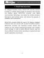
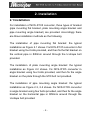
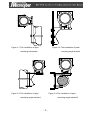
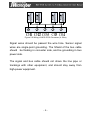
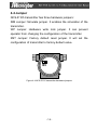
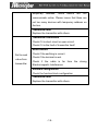
NCS-IF105 Current to Fieldbus Converter
User Manual
Microcyber Inc.
Contents
1. Brief Introduction.................................................................... 1
2. Installation.............................................................................. 2
2.1 Installation ........................................................................ 2
2.2 Wiring ............................................................................... 4
3. Principle and Structure .......................................................... 6
4. Transmitter Configuration .................................................... 10
4.1 Network Topology .......................................................... 10
4.2 Function Blocks...............................................................11
4.3 Configuration.................................................................. 12
4.4 Jumper ........................................................................... 16
5. Maintenance ........................................................................ 17
6. Technical Specification ........................................................ 19
6.1 Basic parameters ........................................................... 19
6.2 Technical performance................................................... 19
6.3 Physical performance .................................................... 20
1. Brief Introduction
As intelligent transition device, NCS-IF105 converter receives
0~20mA or 4~20mA analog signal (4 channels) and converts
into
fieldbus
signal.
NCS-FI105
converter
uses
digital
communication technology, and makes the interface between
field device and controller easier, and reduces the expense of
installation and maintenance.
NCS-IF105 converter fulfills the need of FF fieldbus intelligent
instrument and can connect with several FF fieldbus devices.
NCS-IF105 converter has abundant function blocks and
realizes not only normal measurement function also complex
control strategy. In order to realize different function, user can
choose different function blocks according to requirements and
specific application environment.
-1-
2. Installation
2.1 Installation
For installation of NCS-IF105 converter, three types of bracket
(pipe mounting flat bracket, plate mounting angle bracket and
pipe mounting angle bracket) are provided. Accordingly there
are three installation methods as the following.
The installation of pipe mounting flat bracket: the typical
installation as Figure 2.1 shows. Fix NCS-IF105 converter in flat
bracket using four bolts provided, and then fix the flat bracket on
the vertical pipe in Φ50mm around through the U-shape bolt
provided.
The installation of plate mounting angle bracket: the typical
installation as Figure 2.2 shows. Fix NCS-IF105 converter in
angle bracket using four bolts provided, and then fix the angle
bracket on the plate through the M10 bolt not provided.
The installation of pipe mounting angle bracket: the typical
installation as Figure 2.3, 2.4 shows. Fix NCS-IF105 converter
in angle bracket using four bolts provided, and then fix the angle
bracket on the horizontal pipe in Φ50mm around through the
U-shape bolt provided.
-2-
Figure 2.1 The installation of pipe
Figure 2.2 The installation of plate
mounting flat bracket
mounting angle bracket
Figure 2.3 The installation of pipe
Figure 2-4 The installation of pipe
mounting angle bracket-1
mounting angle bracket-2
-3-
2.2 Wiring
The power and signal of NCS-IF105 converter Transmitter are
sharing one pair of cables (Bus Cable). NCS-IF105 converter is
suggested to use specific Fieldbus cables recommended by the
IEC61158-2. The wiring terminal is at the rear cover side, the
wiring terminal board could be seen when the rear cover is
screwed.
BUS+
BUS-
CH1 CH2 COM CH3 CH4
Figure 2.5 The wiring terminal board of NCS-IF105 Converter
Transmitter
2-Wire
Transmitter
2-Wire
Transmitter
2-Wire
Transmitter
2-Wire
Figure 2.6 Wiring of NCS-IF105 Converter (2- Wire)
-4-
Figure 2.6 Wiring of NCS-IF105 Converter (4- Wire)
Signal wires should be passed the wire hole. Sensor signal
wires are single-point grounding. The Shield of the bus cable
should
be floating in converter side, and be grounding in bus
power side.
The signal and bus cable should not share the line pipe or
trunkings with other equipment, and should stay away from
high-power equipment.
-5-
3. Principle and Structure
NCS-IF105 converter convert input current signal that generate
by most conventional transmitters to fieldbus signal.
NCS-IF105 converter is consisted of five components, as
shown in Figure 3.1.
1)
Terminal board: it is used to connect with fieldbus, current
output signal, A/D board and communication board.
2)
A/D board: it can convert input current signal to digital
signal provided to communication board.
3)
Communication card: it is core component of intelligent
instrument, which implements the communication, control,
diagnosis and maintenance of Foundation Fieldbus.
4)
Isolation
board:
it
is
used
for
isolation
between
communication board and instrument board (power
isolation and signal isolation).
5)
LCD Card (optional): it is used to display function block
parameters.
-6-
Figure 3.1 Schematic diagram of NCS-IF105 converter
l
Size of NCS-IF105 Converter
Figure 3.2 Size of NCS-IF105 Converter (unit: mm)
-7-
l
Structure of NCS-IF105 Converter
Figure 3.3 Structure of NCS-IF105 Converter
1
Front
cover
2
O-ring
3
5
Post
6
Communication
board
7
10
Screw
11
14
Z/X button
15
18
Bottom cover
9
13
17
Terminal
board
Name
plate
Rear
cover
-8-
LCD
cover
Capture
board
Wire
hole
Housing
4
Electronics/LCD
8
Isolation board
12
Screw
16
Pin/block
As the core of NCS-IF105 converter, the Communication Card
connects with terminal board, isolation board, instrument board
and LCD board. The LCD board rotated in four angles is fixed
on the Communication board, as Figure 3.4 shows.
Figure3.4 Assembly structure of the meter
-9-
4. Transmitter Configuration
4.1 Network Topology
FF transmitter supports many kind of connection,As shown in
figure 4.1. The classic connection modes for a FF device is bus
connection, As shown in figure 4.2.The matching resistance on
the both side of terminal ensures a good quality of signal. The
maximum length of fieldbus is 1900 meters and can be
prolonged to 10 kilometers using repeaters.
Primary Control Station
Fieldbus I/O
junction box
FF bus
Point to Point
Bus
Tree
Figure 4.1 FF Network Topology
- 10 -
Max1900 m
FF Bus
FF Bus
Bus Power
with Terminal
Terminal
Field FF
Link Master
device
Figure 4.2 FF Bus Connections
4.2 Function Blocks
Function Block
Resource
Transducer
Block
Display
Transducer
Description
This block contains data from the hardware that is
associated with the resource.
This block converts input/output device variables
into relevant engineering data.
This block configures process variables displayed in
LCD.
This block transmits the input data from the
Analog Input
transducer block to other function block. It has
scaling conversion, filtering, square root and low
cut, etc...
PID Control
This block has a lot of features as set point
treatment (value and rate limiting), filtering and
- 11 -
alarm on PV, feed-forward, output tracking and
others.
Ratio
This block realizes ratio control between two input
data.
This block has four analog inputs that may be
Input Selector
selected by an input parameter or according to a
criterion as first good, maximum, minimum, middle
and average.
This
Signal
Characteristic
block
has
capability
for
two
signal
characteristics based on the same curve. The
second input has an option for swapping “x” to “y”,
and inverse function may be used in signal
characteristic of read-back variables.
This block provides dynamic compensation of a
Lead Lag
variable. It is used normally in a feed-forward
control.
4.3 Configuration
NCS-IF105 transmitter can be configured by the Configurator
software and NCS4000 DCS software of Microcyber Inc,
NI-FBUS Configurator of National Instrument, and DeltaV
system of Rosemount.
l
Environments
1)
Windows 2000 or Windows XP system;
2)
NCS-LD105 Linking Device, H1 Bus Power, H1
Terminal Matcher;
3)
FF Configurator;
- 12 -
l
The
Two point calibration
transmitter
can
be
calibrated
by
the
parameter
CAL_POINT_HI and CAL_POINT_LO:
1)
Input the standard current signal to the channel that
will be calibrated. Such as 4 mA.
2)
Read the actual current value from the parameter
PRIMARY_VALUE of transducer block. For example,
it is 3.9 mA.
3)
Set the mode of transducer block to O/S, and then
change the parameter SENSOR_CAL_METHOD to
“User Trim Standard Calibration”.
4)
Write
the
value
of
4
mA
to
the
parameter
CAL_POINT_LO. If the parameter is written with no
error, the low calibration would be successful. Please
note that calibration value must be in the range of
sensor maximum measurement. The calibration
value must not have much difference from actual
value, or the calibration will be failed.
5)
Set the mode of transducer block to AUTO.
6)
The upper value calibration is the same the lower
value calibration. Please write the new upper value to
the parameter CAL_POINT_HI while calibrating.
l
LCD Configuration
By default, the transmitter LCD displays the parameter
PRIMARY_VALUE value of the first channel of transducer block.
- 13 -
As is shown in the figure 4.3, if user need displays other
parameter of other block, please follow the steps below. (X is
equal to 1, 2, 3 or 4, the LCD display transducer block can
display four kinds of parameter cicely.) The LCD will show
CONFIG_ERR if it receives a wrong configuration parameter.
Please set the mode to O/S and correct the configuration
parameter then set the mode back to AUTO so that it display
normally.
1)
BLOCK_TAG_X: This parameter defines the tag name
of function blocks. For example, if user wants to
display a parameter of AI1 function block, he should
write “AI1
” to this
parameter. Please note that the length of written
char should be equal to 32 bytes. If the length of
char is smaller than 32, please insert blank char to
make its length equal to 32.
2)
RELATIVE_INDEX_X: This parameter defines the
index of the parameter of function blocks. For example,
if user wants to display the OUT parameter of AI1
block, please write 8 to the RELATIVE_INDEX_X.
3)
SUB_INDEX: This parameter defines the sub index of
the parameter of function blocks. For example, if user
wants to display the OUT.VALUE of AI1 block, please
write 2 to this parameter.
4)
MNEMONIC_X: This parameter defines the text which
will be displayed in the LCD. The maximum length of
- 14 -
text is 16 bytes.
5)
DECI_PNT_NUMB_X: This parameter defines the
position of decimal point for displayed value.
6)
ACTIVE_X: This parameter wills active the display
function of the group.
Figure 4.3 LCD Configuration
- 15 -
4.4 Jumper
NCS-IF105 transmitter has three hardware jumpers:
SIM Jumper: Simulate jumper. It enables the simulation of the
transmitter.
WP Jumper: Hardware write lock jumper. It can prevent
operator from changing the configuration of the transmitter.
RST Jumper: Factory default reset jumper. It will set the
configuration of transmitter to factory default value.
Figure 4.4 NCS-IF105 transmitter hardware jumpers
- 16 -
5. Maintenance
Phenomenon
Solution
Transmitter connection
No
Communication
Check the bus connection
Check the polarity of bus power
Check shield of bus cable, if it is single point
earthing
Bus power
Bus power should in the range 9 ~ 32V for the
transmitter.
Bus noise and ripple should fulfill:
1) peak-to-peak value noise is 16mV, 7~39kHz;
2) peak-to-peak value noise is 2V, 47~63HZ, for
non-EX
3) peak-to-peak value noise is 0.2V, 47~63HZ,
for EX
4) peak-to-peak
value
noise
is
1.6V,
3.9M~125MHZ.
Network connection
Check network topology structure
Check terminal matcher and wire connection
Check the length of main trunk and branch
Address conflict
The factory default address if a temporary address
from 0xF8 to 0xFB. If there are more devices with
- 17 -
temporary
address,
some
device
will
not
communicate online. Please insure that there are
not too many devices with temporary address on
the bus.
Transmitter fault
Replace the transmitter with others.
Transmitter connection
Check if it is short circuit or open circuit.
Check if it is the fault of transmitter itself.
Noise disturb
Fail to read
value from
transmitter
Check if the earthing is correct.
Check if the terminal is wet.
Check if the cable is far from the strong
Electromagnetic Interference
Software configuration
Check the function block configuration
Transmitter fault
Replace the transmitter with others.
- 18 -
6. Technical Specification
6.1 Basic parameters
Input signal
4~20mA
Channels
4 Channels
Power supply
9 ~ 32 VDC ;Current Dissipation (static): ≤ 14mA
Fieldbus Signal
Communication Baudrate 31.25kbit/s, current-mode
Insulation
Display
Between housing and terminal board:
500 Vrms (707 VDC)
6 bits digital number and 5 bits characters LCD
display (Optional)
Temperature
- 40 ~ 85℃ (No display)
range
- 30 ~ 70℃ (display)
Humidity Range
0% ~ 100% RH
Start Time
≤ 5s
Protection grade
IP 65
EMC
Designed to comply IEC 61000
6.2 Technical performance
Accuracy
< 0.05 %;
Input impedance
150 Ω
Temperature
effect
< ± 50 ppm/℃
- 19 -
6.3 Physical performance
Electrical
1/2 - 14 NPT
connection
Material
Construction
Weight
of
Aluminum
1.1 kg
- 20 -
Marketing Contact: Guangshu Jin
Tel: +86-24-83602051
Fax: +86-24-83602985
E-mail: [email protected]
Website: www.microcyber.cn
Address: No.19 Feiyun Road, Hunnan New
District, Shenyang, China 110179