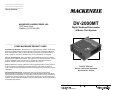
1
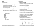
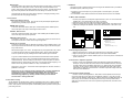
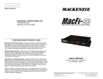
__________________
__________________
__________________
Return Address
MACKENZIE LABORATORIES, INC.
1163 Nicole Court
Glendora, CA 91740 USA
DV-2000MT
Digital Autoload Storecaster
& Music Thru System
------------------------------------------------------------------------------------------------------------------
OTHER MACKENZIE PRODUCT LINES
Digital Message Repeaters - Mackenzie's line of Digital Message repeaters are the ideal
audio announcement solutions for Public Address, Amusement, Entertainment, Museum
and Exhibit applications. Self contained solid state systems offer unparalleled reliability. A
variety of channel, connection, bandwidth and memory configurations are available.
Controls and Peripherals - Many applications require additional equipment to optimize
the performance of Mackenzie products. This area focuses on items developed or sourced
for their compatibility, ease of use and value. Included are, input/output controllers,
speakers, amplifiers, motion sensors and pushbuttons among others.
Transit - Mackenzie is making a difference in transit applications with innovative solutions
for ADA compliance and Passenger Information Systems. These products address a
variety of audio and text messaging requirements and support both in-vehicle and wayside
installations.
User's Manual
Version 1.0 Revised 10/21/2004
Doc 99-20-181 - $25.00
Overhead Page Management - Mackenzie's OPM and FE series of Digital Page
Stacker/Repeater and Feedback Eliminators offer advanced features for the most difficult
paging and intercom applications. A unique design makes feedback virtually impossible by
recording then repeating pages which opens the loop between the input microphone and
speakers. Various models are available to support simple repetition, multiple page stacking
and multiple input channels.
MACKENZIE LABORATORIES, INC.
1163 Nicole Court
Glendora, CA 91740 USA
Tel: (909) 394-9007 Fax: (909) 394-9411
Email: [email protected]
Web: www.macklabs.com
Warranty & Registration Card for the
DV-2000MT - Digital Autoload Storecaster & Music-Thru System
General Safety Instructions
Always follow these basic safety precautions when using the system:
1.
2.
3.
4.
5.
6.
7.
8.
9.
10.
11.
12.
13.
14.
15.
Read carefully and understand all instructions.
Follow all warnings and instructions marked on the product.
DO NOT block or cover ventilation slots and openings.
DO NOT place the product in a closed enclosure or cabinet unless proper ventilation is provided.
Never spill liquid on the product or drop objects into the ventilation slots and openings. Doing so
may result in serious damage to the components.
Repair or service must be performed by a factory authorized repair facility.
DO NOT staple or otherwise attach the power supply cord to building surface.
DO NOT use the product near or in wet or damp places, such as wet basements.
DO NOT use extension cord. Install within 6 feet of a grounded outlet receptacle.
DO NOT install during lightning storm.
Never touch un-insulated wires or terminals unless the unit is disconnected from both power and
the rest of the phone system.
Use Caution when installing or modifying configuration switches or control lines.
Install in a protected location where no one can step on, or trip over, power and line cords.
The unit must be securely attached to a wall board, rack or table mounted.
Use correct power source. Use only the power pack supplied.
Date:________________________
Purchaser:
___________________________________________________
Address:
___________________________________________________
City:
__________________
Phone: __________________
Seller:
If any wiring from the system leaves the premises,
you must use proper electrical protectors.
Regulations:
State: ______
Zip:
____________
Fax: __________
Email: ____________
_______________________________________________________
Address:_______________________________________________________
City:
__________________
Phone: __________________
CAUTION:
Serial No.: _______________________
State: ______
Zip:
____________
Fax: __________
Email: ____________
Return warranty card via:
FAX: (909) 394-9411
MAIL: Address on reverse side
ONLINE: www.macklabs.com/registration.html
-----------------------------------------------------------------------------------------------------------------NOTES
____________________________________________________________________
FCC (Part 15) Radio Frequency Interference
The DV-2000MT generates and uses radio frequency energy and if not installed and used in strict
accordance with the manufacturer's instructions, may cause interference to radio and television
reception. Unit complies with the limits for Class A devices in accordance with the specifications in
Subpart J of Part 15 of the FCC Rules. This testing is designed to provide reasonable protection
against such interference. However, there is no guarantee that interference will not occur in a particular
installation. If this equipment does cause interference to radio or television reception, which can be
determined by turning the unit off and on, the user is encouraged to try to correct the interference by
one or more of the following measures:
____________________________________________________________________
____________________________________________________________________
____________________________________________________________________
-Reorient the radio or TV receiving antenna.
-Relocate the unit with respect to the radio or TV receiver or vice-versa.
-Plug the unit into a different outlet so that it and the radio or TV receiver are on different branch
circuits
____________________________________________________________________
____________________________________________________________________
-If necessary, the user should consult the dealer or an experienced radio/television technician for
additional suggestions.
____________________________________________________________________
____________________________________________________________________
____________________________________________________________________
•
•
•
•
•
The silence portion between messages is not included in the maximum recording time.
The audio should be set to a nominal level of 0VU = -4dBm.
For best results, the audio should be filtered to cutoff any frequencies higher than 3.4kHz for
the STD version and 6.8kHz for the PRO version.
The dynamic range of the production should be held low so as to allow the production to be
recorded at the highest possible level without exceeding +5VU = +1dBm.
The system requires 6 seconds of constant audio at a level greater than -20dBm for the
system to acknowledge the production and start recording. This is required so that the
system can discriminate between tape noise and message material.
Table of Contents
1.
2.
7. WARRANTY, SERVICE & RETURNS
The industrial grade housing and quality construction of the Mackenzie DV-2000MT virtually
eliminates the need for service or maintenance. There are no user-serviceable components
within the Mackenzie DV-2000MT. Refer all servicing to the factory.
3.
7.1 Warranty Coverage:
The Mackenzie DV-2000MT is tested and checked before shipment and are guaranteed
against defective material or workmanship for a period of three (3) year from the date of
purchase. Should trouble ever develop, contact the Factory directly by telephone or in writing.
If it is determined that the equipment requires Factory service, return it to the Factory. If our
inspection shows that the trouble was caused by defective material or workmanship, we will
repair or replace the equipment without charge and return prepaid. Repairs made necessary
by abuse, improper use, unauthorized service or maintenance, and/or improper installation, as
well as out of warranty repairs, will be charged at our regular repair prices in effect at the time.
The obligation under this warranty shall be limited to the replacement, repair or refund of any
such defective device within the warranty period.
This warranty is in lieu of and excludes all other warranties, expressed or implied, and in no
event shall MACKENZIE be responsible for damage to other equipment or property, for any
anticipated profits, consequential damages, loss of item, or other operation or use of this
product, and MACKENZIE’S maximum liability shall not ever be greater than the price paid for
the equipment. This warranty gives you specific legal right. Your rights may vary from state to
state. Inquiries regarding use, repair and service should be made to:
MACKENZIE LABORATORIES, INC.
1163 Nicole Court, Glendora, CA 91740 USA
Telephone: (909) 394-9007
FAX No: (909) 394-9411
Email: [email protected]
WWW: www.macklabs.com
7.2 What we ask you to do:
To get warranty service for your DV-2000MT system, you must provide proof of the date of
original purchase. In the event you need to ship your DV-2000MT system to the factory for
service, call us for a return authorization number. When you ship your DV-2000MT system,
you must prepay all shipping cost. We suggest that you retain your original packing material in
the event that you need to ship your DV-2000MT system. When sending your DV-2000MT
system to the factory, include your name, address, phone number, proof of date of purchase,
and a description of the operating problem. After repairing or replacing your DV-2000MT
system, we will ship it to your return address at no cost to you within the USA. Repair or
replacement of your DV-2000MT system at our factory is your exclusive remedy.
4.
5.
6.
7.
OVERVIEW: ............................................................................................ 4
1.1 Features and Benefits:.......................................................................... 4
1.2 General Specifications: ......................................................................... 4
Installation: .............................................................................................. 5
2.1 Wall or Table Installation:...................................................................... 5
2.2 Connecting the power pack................................................................... 5
2.3 Connection to Telephone equipment ..................................................... 5
2.4 Connection to the PA equipment ........................................................... 5
Operation: ............................................................................................... 5
3.1 Message Downloading:......................................................................... 5
3.1.1. Message Download Mode 1 - Replace All ..................................... 6
3.2 Automatic message playback................................................................ 6
3.3 Manual message playback.................................................................... 7
3.4 Pushbutton descriptions........................................................................ 7
3.5 LED (Light Emitting Diodes) descriptions............................................... 10
3.6 Audio adjustments ................................................................................ 10
3.7 Slide Switch descriptions ...................................................................... 11
3.8 Connections ......................................................................................... 12
Power failure recovery ............................................................................. 12
Troubleshooting guide.............................................................................. 13
Audio Tape Production Format: ................................................................ 13
WARRANTY, SERVICE & RETURNS ...................................................... 14
7.1 Warranty Coverage:.............................................................................. 14
7.2 What we ask you to do:......................................................................... 14
7.3 What this warranty does not cover:........................................................ 14
Shipping Container Contents
The following items should be found in the container of the DV-2000MT Autoload Storecaster & MusicThru System.
- DV-2000MT System
- Power pack
- Audio cable
- Mounting hardware
- User's manual
7.3 What this warranty does not cover:
This warranty does not cover defects resulting from accidents, damage while in transit to
factory, alterations, unauthorized repairs, failure to follow instructions, misuse, fire, flood, and
acts of God.
14
3
1. OVERVIEW
The DV-2000MT is a versatile Message-On-Hold and Storecasting system. The MT combines
high quality audio playback, background music and remote control features for use in even the
most demanding applications.
1.1
Features and Benefits:
The DV-2000MT is a highly reliable audio playback system specifically designed for
Message-On-Hold and Storecasting applications. The system allows music and marketing
messages while clients are waiting on-hold or in your retail location. This heightens
awareness and minimizes frustration, thus increasing sales.
Message material is loaded into the system via a ruggedized, electronically controlled
cassette mechanism originally designed for automotive applications and providing years of
reliable service. Messages are digitized and stored in non-volatile FLASH memory that
protects them from loss during power outage.
The DV-2000MT supports up to 20 individual messages. The Background Music(BGM)
input is for combining messages with an external music source such as CD or satellite. A
built -in timer lets the user determine the time between message plays.
Multiple audio outputs(600ohm,8ohm) with level control, Aphex®, and high quality sampling
allow the sound of the DV-2000MT to be optimized for almost any phone or public address
system, insuring that the message gets heard.
1.2
General Specifications:
Power:
12VDC
Audio Fidelity
3.4kHz(STD) / 6.8kHz(PRO)
60dB Signal to Noise
BGM Input:
RCA, mono, 10K ohm
Audio Outputs:
RCA, mono, 600 ohm
RCA, mono, 1W @ 8ohm
Remote Trigger:
RJ-12, trigger, relay, audio out
Manual Controls:
BGM level, BGM fade level, Aphex mix, Output volume, Eject, Speaker,
Delay
Switches:
Play mode, Delay min/sec
Package:
Painted steel chassis
5. Troubleshooting guide
Before contacting the factory, please review the following answers to some common problems.
No LEDs are active on the DV-2000MT.
•
When a tape is inserted, and before audio is detected by the system, all LEDs will be off.
•
Verify that the AC-DC power adapter is plugged into non-switched AC power outlet.
•
Verify that the power connector is plugged completely into the jack on the DV-2000MT.
The system will not mechanically load the tape into the system
•
Push the cassette tape completely into the DV-2000MT.
•
Verify that the AC-DC power adapter is plugged into non-switched AC power outlet.
•
Verify that the power connector is plugged completely into the jack on the DV-2000MT.
The system ejects the tape immediately after it is loaded.
•
The system will eject the tape immediately after loading it, if the memory is full.
•
The system will eject the tape immediately after loading it, if all of the messages are used.
•
The system will eject the tape immediately after loading it, if it is an endless loop tape.
The Record LED never comes on after the cassette tape is loaded into the system
•
Verify that the tape was inserted right side up.
•
If the tape is blank, the Record LED will never come on.
•
Verify that the nominal level of the Audio recorded on the tape is over –20dB.
After recording the tape, the tape ejected, and the system is not playing a message.
•
Pressing, and holding the edit/eject button while recording will eject the tape immediately.
•
Verify that the tape was inserted right side up.
•
If there is no audio on the tape, it will eject automatically when it reaches the end of the
tape.
Can’t hear anything from the audio output
•
If both Record and M-O-H LEDs are off, there is no audio being output by the system.
•
Verify that the RCA to RCA connector is securely attached to the DV-2000MT and the
phone system.
•
Turn the output level adjustment clockwise to increase the Audio output level.
•
Use the 8 ohm output instead of the line level output.
Can’t hear anything through the monitor speaker
•
If both Record and M-O-H LEDs are off, there are no recorded messages on the system.
•
Press the Speaker button so that it locks in the depressed position.
•
If the audio output is adjusted low, the level from the monitor speaker will also be low.
The system didn’t record all the messages on the tape
•
If there is noise in the silence portions separating the messages on the cassette tape,
multiple messages can get grouped into a single message location on the system.
6. Audio Tape Production Format:
Aphex®, Aphex Aural Exciter and AX are patented, registered trademarks of Aphex Systems, Ltd.
4
•
•
Messages must be recorded on the left channel or track A.
The length of individual messages do not have to be the same, but the total length of all
messages should not exceed the total memory capacity of the unit.
13
Music Interval
Two Rotary switches and a slide switch make up the Music Interval setting. The two rotary
switches allow for a setting from 00 to 99. The left rotary switch represents the “tens”
position, while the right rotary switch represents the “ones” position. The slide switch to the
right of the rotary switches sets whether the 00 to 99 setting is in minutes or seconds.
These switches are read by the system during operation, so changing the setting can be
performed while the unit is playing messages.
3.8 Connections
12VDC, 2.5mm Barrel connector
The system is powered by 12VDC. Use only the AC-DC power adapter supplied by the
manufacturer to guarantee proper operation.
BGM IN, RCA connector
A 10K ohm, transformer isolated, audio input. When installing the DV-2000MT system,
connect this input to the output of the background music source.
2. Installation:
This section provides complete instructions for mounting the DV-2000MT. Before you install the
DV-2000MT system, make sure you have:
-A message or music on hold input on your phone system or line level input to your public
address system.
-A non-switchable 110VAC electrical outlet near the location where the unit is to be installed.
2.1 Wall or Table Installation:
1. Locate a proper space on the telephone equipment board or wall. You can mount the DV2000MT unit in one of three positions: flat, side, or horizontal.
2. Position the unit on the board; mark the mounting hole locations.
3. Using the mounting screws provided, secure the DV-2000MT system to the board or wall.
4. If table top mounting the DV-2000MT, stick the enclosed rubber feet on the bottom of the
unit.
A
LINE OUT, RCA connector
A 600 ohm, transformer isolated, Audio output. When installing the DV-2000MT system,
connect this output to the phone system first.
by
R
Mounting Options:
A. Back of unit
against wall - flat ( 10" x 8" )
EJECT
REC STOP
M USIC INTERVAL
TENS
ONES
M IN
EJECT
SEC
R EC
PL AY MODE
AUD IO
Remote, RJ11-6 connector
An auxiliary connector provides an alternative to interface to the DV-2000MT system. This
connector provides the line level audio output, Start activation signal, and a Normally open
relay contact closure.
Start Activation signal, Pins 1 and 6 – Shorting these two pins together with a relay contact
or a switch will put the system into manual playback mode. When in manual playback
mode, the system will only play messages when a Start activation signal is received.
To get out of manual activation mode, deactivate and then activate the monitor speaker.
Playing relay, Pins 2 and 5 – When in automatic playback mode, these contacts will be
closed continuously. When recording, they will be open. When the system is in manual
playback mode, the contacts will only close when a pre-recorded message is playing. The
contacts on the relay are rated at 24VDC at 1 amp, non-inductive load.
Audio output - Pins 3 and 4 – The line level audio output signal from the RCA connector is
paralleled on these pins.
Note: Even if you are in manual message playback mode, a message download will
configure the system for Automatic message playback. After messages are
downloaded the system will immediately begin playback. The user must initiate
manual message playback by "shorting" the two control pins of the Remote
connector after a message download.
4. Power failure recovery
The DV-2000MT uses FLASH memory which is not dependent upon power or battery backup to
retain its memory. This eliminates problems associated with brown outs or unexpected power
losses. When power is returned, the system will immediately start the operation it was in prior to
power being removed.
12
C
DIGITAL AUTOLOAD STORECASTER & MUSIC THRU SYSTEM
DV-2000 MT SERIES
SPKR OUT, RCA connector
An amplified, 1 watt into 8 ohm, Audio output. Use this Audio output if the Audio from the
Line output can’t drive the on-hold circuit to a high enough level.
B
MUSIC O NLY
BGM FADE
M USIC & M ESSAGE
SPEAKER
DOWN
12 VDC
_
+
L EVEL
BG M IN
APHEX
LINE O UT
L EVEL
SPKR OUT
B. Left side of unit
against wall - side ( 2.2" x 8" )
MESSAG E ONLY
UP
REMO TE
C. Left side of unit
against wall horizontally ( 8" x 2.2" )
2.2 Connecting the power pack
1. Plug the power pack into a 110VAC power outlet which is not connected to a switch.
2. Plug the power plug into the DV-2000MT system’s power jack marked POWER.
3. There is no power switch on the DV-2000MT system, so as soon as power is connected, the
system will be active.
2.3 Connection to Telephone equipment
1. Connect one side of the supplied RCA cable to the telephone equipment's Message-OnHold input. Connect the other side of this cable to the DV-2000MT's LINE OUT. There are
two audio outputs on the DV-2000MT, LINE OUT (Low, +4dB into 600 ohms), and SPKR
OUT (High, 1W into 8 ohms). Use the LINE OUT first adjusting the audio output volume
potentiometer to obtain the correct audio level. If this does not provide enough audio level,
then switch to the SPKR OUT.
2.4 Connection to the PA equipment
1. Connect one side of the supplied RCA – RCA cable to the PA amplifier’s line level input.
Connect the other side of this cable to the DV-2000MT’s LINE OUT. There are two Audio
outputs on the DV-2000MT, LINE OUT(Low, +4dB into 600 ohms), and SPKR OUT(High, 1W
into 8 ohms). Use the LINE OUT first adjusting the audio output volume potentiometer to
obtain the correct audio level. If this does not provide enough audio level, then switch to the
SPKR OUT.
5
DIGITAL AUTOLOA D STORECAST ER & MUSIC THR U SYSTEM
DV-2000 MT SERIES
by
R
EJEC T
R EC STOP
MU SIC INTE RV AL
T ENS
BGM In
This sets the overall level of the background music being fed into the DV-2000MT. Turning
this potentiometer counter clockwise will lower the BGM level. Turning this potentiometer
clockwise will raise the BGM level.
ON ES
MIN
EJEC T
SEC
R EC
P LAY MODE
A UD IO
MU SIC ONLY
B GM FAD E
MU SIC & ME SS AGE
S PEA KE R
D OWN
1 2VD C
_
+
LE VE L
BGM IN
AP HEX
LIN E OU T
ME SS AGE ON LY
UP
LEV EL
S PKR OUT
RE MOT E
BGM Fade
Two pushbuttons are provided on the top cover allowing the user to set the amount of
“ducking” to be applied to the BGM audio when a pre-recorded message is played by the
system. The BGM audio is mixed with the pre-recorded message audio, and this setting
governs the amount of BGM audio being mixed. “Ducking” is the amount which the BGM
audio level is attenuated, or lowered.
BGM Fade Down pushbutton – Black, momentary
Pressing this button will increase the ducking amount, or, in other words, lower the BGM
audio being mixed in with the audio output when a pre-recorded message is played.
Pressing the button one time will attenuate the BGM audio approximately 1dB. If the button
is pressed and held, the BGM level will be lowered approximately 8dB per second.
3. Operation:
3.1 Message Downloading:
When you receive the new DV-2000MT Storecasting system, its memory will be blank. To
load new messages into the DV-2000MT’s memory, simply insert a pre-recorded, and properly
formatted, cassette tape into the DV-2000MT unit. Make sure to insert the tape with the Audio
side up.
When a new tape is inserted, the DV-2000MT will automatically rewind the cassette to the
beginning and start playing it. The DV-2000MT will record the audio program(s), ignoring the
silence segments on the cassette. When the Audio program on the tape starts, the red Record
light will come on signifying that Audio is being recorded. At the end of the Audio program,
when the DV-2000MT detects 6 seconds of silence, the Record LED will go out. The system
will keep playing the tape while it “looks” for another message on the tape. If another message
exists, the red Record light will go on signifying that another message is being recorded.
When the last message on the tape is recorded, signified by 10 seconds of silence, the system
will automatically rewind the cassette tape.
3.1.1 Message Download Mode 1 - Replace All
When this mode is used, the system will erase all the messages in memory as soon as
the tape is inserted. The system will begin recording the messages from the cassette
tape into memory starting from message #1 and continuing through the last message on
the tape. Use this mode any time all of the messages on the DV-2000MT system need to
be updated.
BGM Fade Up pushbutton – Black, momentary
Pressing this button will decrease the ducking amount, or, in other words, increase the
amount of BGM audio being mixed in with the audio output when a pre-recorded message
is played. Pressing the button one time will raise the BGM audio approximately 1dB. If the
button is pressed and held, the BGM level will be raised approximately 8dB per second.
3.7 Slide Switch descriptions
Several slide switches are provided on the top cover of the DV-2000MT. These switches
control the functions described below:
Play Mode
The DV-2000MT system has three play modes, Music Only, Message Only, and Music and
Message. A three position slide switch sets the mode of the system.
Music Only – No pre-recorded messages are played when the system is in this mode. The
system will simply route the BGM audio directly to the output.
Message Only – Pre-recorded messages will be played sequentially based on the Music
Interval setting. The BGM audio will be muted, however. No audio will be present on the
audio output connector between pre-recorded message plays.
Music and Message (Default) – This mode allows Pre-recorded messages to be played
sequentially based on the Music Interval setting. When a message is playing, the BGM audio
will be mixed in with the pre-recorded audio. Between pre-recorded message plays, the BGM
Audio will be routed directly to the audio output.
Important: Once a tape is inserted into the DV-2000MT system, in this mode, all of
the messages in memory will be deleted immediately. Even if the tape is then
ejected prior to recording any audio, the DV-2000MT’s memory will be empty.
3.2 Automatic message playback
After messages have been recorded into memory, the DV-2000MT will automatically begin
playing them through the audio outputs. There is no control, or user input, required to
initiate the playback. The green, Audio LED will light whenever the system is playing
messages. Messages will be played back sequentially.
The messages in memory are automatically played back sequentially with a user
programmed delay time inserted between them. This delay time is set using the two rotary
switches on the top cover. The rotary switches provide a range between 0 and 99. A slide
switch to the right of the rotary switches allows the setting to be represented in seconds, or
in minutes.
6
11
Speaker pushbutton – Black, locking
A monitor speaker, on the front side of the unit, allows the local user to hear the Audio being
output by the DV-2000MT. Pressing this button will activate the monitor speaker.
Releasing the button will deactivate the monitor speaker.
In between pre-recorded message plays, the DV-2000MT will output the background music,
BGM, audio to the audio output. The DV-2000MT will gently fade the BGM audio up after a
pre-recorded message is played, and it will gently fade the BGM audio down just prior to a
pre-recorded message play.
3.3 Manual message playback
The volume of the monitor speaker is determined by the volume setting of the Audio output.
If the phone system requires a particularly low level from the DV-2000MT, the volume of the
monitor speaker will also be low.
Note: Do not adjust the Audio output level adjustment in order to hear the monitor
speaker level better. Doing this will adjust the level of the Audio output which may
not be acceptable.
3.5 LED (Light Emitting Diodes) descriptions
Four LEDs are provided on the top of the DV-2000MT unit to display the current status of the
system.
If the user issues another Start activation while a message is playing, the DV-2000MT will stop
the currently playing message and immediately start the next message.
Eject LED, Yellow
This LED will light whenever the tape is ejected, i.e. no tape in the system. When a tape is
inserted, and loaded, i.e. tape is completely inside the machine, this LED will go out.
If the Start activation is held active indefinitely, the DV-2000MT will play messages
sequentially, with no pause time between them until the Start activation is removed. When the
Start activation is removed, the system will finish playing the active message and then stop
and await the next Start activation. The user cannot stop a message once it has been started
on the DV-2000MT.
Record LED, Red
This LED will light when the DV-2000MT starts recording an Audio program, and will go out
when the recording process stops.
To get out of manual activation mode, deactivate and then activate the monitor speaker.
The Record LED will blink one time when the DV-2000MT is powered on, indicating that the
memory operational.
M-O-H LED, Green
This LED will light whenever the DV-2000MT is in automatic playback mode and playing
messages, or outputting the BGM audio. When the system is in manual playback mode,
this LED will light only when a pre-recorded message is actually playing.
3.6 Audio adjustments
There are three potentiometers and two pushbuttons on the DV-2000MT system allowing the
user to tailor the BGM level, the audio output level and high frequency response. These
potentiometers are located on the front side of the device directly above the audio connectors.
Audio level
The level of the both 600 and 8 ohm Audio outputs are simultaneously adjusted using the
Audio level adjustment pot. Turning this potentiometer counter clockwise will lower the
Audio level. Turning this potentiometer clockwise will raise the Audio level.
Aphex®
A special, psycho-acoustical processing extends the high frequency response of the DV2000MT. Turning this potentiometer clockwise amplifies the high frequencies while turning
it counter clockwise attenuates the high frequencies.
10
A manual “Start” control input is provided on the Remote connector of the DV-2000MT. The
user initiates manual message playback by “shorting” the two control pins, provided on the
Remote connector, together. When the system is in manual playback mode, the Audio LED
will only light when the DV-2000MT is playing a pre-recorded message. When in this mode,
the system will only play messages when the Start input is activated by the user, ignoring the
delay time setting on the rotary switches. The system plays the messages in the same order
as they would be played in automatic mode. One message is played per Start activation.
Note: Even if you are in manual message playback mode, a message download will
configure the system for Automatic message playback. After messages are downloaded
the system will immediately begin playback. The user must initiate manual message
playback by "shorting" the two control pins of the Remote connector after a message
download.
3.4 Pushbutton descriptions
Two pushbuttons are provided on the DV-2000MT system.
Eject / Rec Stop pushbutton – Red, momentary
Allows the user to stop the recording process, in several ways, and/or eject the tape.
-When the system is not recording, the button functions as an Eject button.
-When the DV-2000MT is recording audio, (whenever the Record LED is on) pressing this
button momentarily will stop the recording and save the Audio which was just recorded.
The system will rewind the tape, but not eject it.
-If this button is pressed and held for two seconds while the DV-2000MT is recording, the
message just recorded will be deleted, and the tape will be ejected without being
rewound.
-If the button is pressed momentarily while the DV-2000MT is recording audio, and then
pressed momentarily again, the system will stop the recording process, save the Audio
just recorded, and eject the cassette tape without rewinding it.
7
Model DV-2000 MT & DV-2000 MT PRO
DIGITAL AUTOLOAD MESSAGE-ON-HOLD & MUSIC THRU SYSTEM
1
2
NOTE:
Insert Pre-Recorded tape Cassette as shown ( Tape up,
Facing label ), system will rewind tape then start loading
( Red LED is on ) at the end of downloading the
message (s), the Red LED will turn off, system will
rewind the tape. It will automatically start playing the
message (s) from the digital audio memory Enabled.
3
4
1
EJECT / RECORD STOP PUSH-BUTTON:
This ejects the tape when the system is playing a
message. If pressed during the recording process
the recording will be stopped.
2
NO TAPE LED:
Yellow light ON indicates there is no cassette
inserted. Yellow light OFF indicates the cassette is
in place.
3
RECORD LED:
Used to determine tape loading mode. Red light
ON, indicates message (s) is being loaded into
memory.
5
6
7
8
9
17
10
4
PLAYING LED:
This green LED is ON when the system is playing
a Pre-Recorded message.
5
SPEAKER PUSH-BUTTON:
Turns local Monitor ON/OFF.
6
POWER:
Insert supplied power adapter.
16
15
11
14
12
13
7
BGM LEVEL:
Adjusts level of external music source.
8
BGM INPUT:
Connect to external source of music.
The Mackenzie Dynavox
DV-2000 MT & MT PRO Quikey
V 1.0 Feb. 27, 2004
Mackenzie Laboratories, Inc.
1163 Nicole CT, Glendora, CA 91740 USA
TEL (909) 394-9007
FAX (909)394-9411
www.macklabs.com
8
9
APHEX MIX:
Adjusts the amount of high frequency
enhancement necessary to deliver the best
overall system performance.
10
AUDIO OUTPUT (LINE):
Audio output level of up to +4dB into 600 ,
this is a standard level for most applications.
11
AUDIO OUTPUT (POWER):
Audio output level of up to 1W into 8 ohm. Use this
output if more drive is needed to reach a more
comfortable listening level.
12
LEVEL:
Adjusts the volume to the line level
or power audio outputs.
13
AUXILIARY REMOTE CONNECTOR:
Used for external remote control
applications where single step or play on
command is required, Contact activation
(1,6) Relay output (2,5) and Audio line (3,4).
14
MONITOR SPEAKER:
Allows user to preview message
recording and play back.
15
BGM FADE UP / DOWN PUSH-BUTTON:
Adjusts the Amount the BGM input is
ducked when a message is played.
16
PLAY MODE SWITCH:
UP
= music only.
MID. = music & message.
DOWN = message only.
17
MUSIC INTERVAL
MINUTE/SECOND SWITCH: Select
between minute or second mode.
TENS AND ONES ROTARY: To set musical interval
between message playing. Set the rotary switches to the
desired time between 00 and 99.
9