1
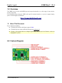
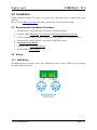
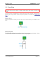
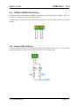
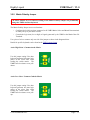
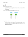
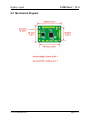
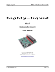
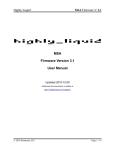
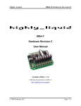
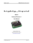
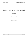
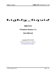
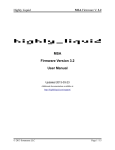
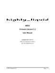
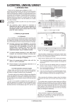
UMR2
User Manual
Hardware RevC – Firmware V1.0
Updated 2014-02-05
Additional documentation and support available at:
http://forum.highlyliquid.com/
© 2012 Sonarcana LLC
Page 1 / 11
Highly Liquid
UMR2 RevC / V1.0
Table of Contents
1.0 Overview..............................................................................................................3
1.1 About This Document............................................................................................................3
2.0 Feature Diagram...................................................................................................3
3.0 Installation...........................................................................................................4
3.1 Recommended Installation Procedure...................................................................................4
3.2 Wiring...................................................................................................................................4
3.2.1
3.2.2
3.2.3
3.2.4
3.2.5
3.2.6
MIDI Wiring..............................................................................................................................................4
Power Wiring.............................................................................................................................................5
PRGM and MODE Switches.....................................................................................................................6
Remote LEDs (Optional)...........................................................................................................................6
Matrix Polarity Jumper..............................................................................................................................7
Switch Matrix Wiring................................................................................................................................8
3.3 Setup.....................................................................................................................................9
3.3.1 Setup Procedure.........................................................................................................................................9
4.0 Operation...........................................................................................................10
4.1 Mode...................................................................................................................................10
4.2 STBY/ACT LEDs................................................................................................................10
5.0 Mechanical Diagram............................................................................................11
© 2014 Sonarcana LLC
Page 2 / 11
Highly Liquid
UMR2 RevC / V1.0
1.0 Overview
The UMR2 can be used to add MIDI input and output functionality to a wide range of non-velocitysensitive keyboards.
For information about using the UMR2 with specific keyboard models, or to post a support inquiry,
please visit the Highly Liquid Forum:
http://forum.highlyliquid.com/
1.1 About This Document
Key to character formatting:
●
Clickable links to tables and figures appear in blue.
●
Clickable links to sections within the document are underscored.
●
Sections of the manual that have changed significantly since the previous firmware version are
highlighted in yellow.
2.0 Feature Diagram
© 2014 Sonarcana LLC
Page 3 / 11
Highly Liquid
UMR2 RevC / V1.0
3.0 Installation
UMR2 installation consists of two parts: wiring and setup. Both parts must be completed for correct
operation.
Please visit the UMR2 support forum for details regarding specific host keyboard models.
3.1 Recommended Installation Procedure
1. Disconnect power supply and remove any batteries from host keyboard.
2. Complete UMR2 MIDI Wiring, Power Wiring, and PRGM and MODE Switch Wiring.
3. Power host keyboard and test UMR2 “software thru” functionality to verify wiring in step 2.
4. Disconnect power supply and remove any batteries from host keyboard.
5. Set Matrix Polarity Jumper.
6. Complete UMR2 Switch Matrix Wiring.
7. Perform UMR2 Setup Procedure.
3.2 Wiring
3.2.1 MIDI Wiring
Wire MIDI connectors as shown. Pins 4 and 5 (MIDI IN) and pins 2, 4 and 5 (MIDI OUT) are used per
the official MIDI specification.
© 2014 Sonarcana LLC
Page 4 / 11
Highly Liquid
UMR2 RevC / V1.0
3.2.2 Power Wiring
CAUTION: Reverse power polarity or supply voltages greater than 6VDC can destroy the
UMR2.
For correct operation, the UMR2 must be supplied with between 3VDC and 6VDC. Select one of the
following power wiring methods. Details for specific keyboards can be found at the UMR2 support
forum.
Method A (Direct)
If the host keyboard has suitable power rails, these can be connected directly to the UMR2 as shown
below.
Method B (Regulated)
The UMR2 requires additional power regulation circuitry when connecting to certain keyboards. In these
cases, the included zener diode and resistor can be used as a voltage regulator.
© 2014 Sonarcana LLC
Page 5 / 11
Highly Liquid
UMR2 RevC / V1.0
3.2.3 PRGM and MODE Switch Wiring
A PRGM switch is used during the UMR2 setup procedure and during firmware updates. Wire any
momentary or latching switch (not included) as shown.
A MODE switch is used to select the UMR2 mode of operation. Wire any latching switch (not included)
as shown.
3.2.4 Remote LEDs (Optional)
If desired, remote STBY and ACT LEDs can be attached to the UMR2 as shown below. Current limiting
resistors (typical value of 1kΩ is shown) must limit LED current to 10mA or less.
© 2014 Sonarcana LLC
Page 6 / 11
Highly Liquid
UMR2 RevC / V1.0
3.2.5 Matrix Polarity Jumper
CAUTION: Failure to set or incorrect setting of the Matrix Polarity Jumper can permanently
damage the UMR2 and host keyboard.
The Matrix Polarity Jumper serves two functions:
•
Configures the built-in resistors connected to all UMR2 Matrix Select and Matrix Data terminals
as either pull-up or pull-down resistors.
•
Controls the logic state (low or high) of signals generated by the UMR2 at the Matrix Data I/O
Terminals.
Use a piece of wire to connect only one side of the jumper as shown in the diagrams below.
Details for specific keyboards can be found at the UMR2 support forum.
Active High Select / Common Anode Matrix
Use this jumper setting if the host
keyboard generates high-state logic
pulses at the select lines when
reading the switch matrix. The
UMR2 built-in resistors act as pulldowns.
Active Low Select / Common Cathode Matrix
Use this jumper setting if the host
keyboard generates low-state logic
pulses at the select lines when
reading the switch matrix. The
UMR2 built-in resistors act as pullups.
© 2014 Sonarcana LLC
Page 7 / 11
Highly Liquid
UMR2 RevC / V1.0
3.2.6 Switch Matrix Wiring
CAUTION: Incorrect wiring of the UMR2 to the host switch matrix can permanently damage the
UMR2 and host keyboard.
The UMR2 supports switch matrices with up to 9 select lines and up to 8 data lines. Wire the host switch
matrix to the UMR2 as follows:
•
Connect each of the host select lines to one of the UMR2 Matrix Select Input Terminals.
•
Connect each of the host data lines to one of the UMR2 Matrix Data I/O Terminals.
Connect select lines only to UMR2 Matrix Select Input Terminals. Connect data lines only to UMR2
Matrix Data I/O Terminals. Within each category, the lines can be connected in any order.
For matrices with fewer than 9 select lines or fewer than 8 data lines, leave the unused UMR2 terminals
unconnected.
Wiring details for specific keyboards can be found at the UMR2 support forum.
© 2014 Sonarcana LLC
Page 8 / 11
Highly Liquid
UMR2 RevC / V1.0
3.3 Setup
After the UMR2 has been wired to the host keyboard, the UMR2 Setup Procedure must be completed.
The purposes of the setup procedure are the following:
•
Set the MIDI channel of the UMR2 for both MIDI input and output.
•
Set the MIDI note number corresponding to the lowest (leftmost) note on the host keyboard.
•
Allow the UMR2 to “learn” the keyswitch matrix configuration of the host keyboard.
Important notes:
•
In addition to the host keyboard in which the UMR2 is being installed, the setup procedure
requires the use of a second external MIDI keyboard that is used to send a single note to the
UMR2 in step 5. The MIDI Out port of the external MIDI keyboard should be connected to the
MIDI In port of the UMR2. If a MIDI keyboard is not available, this step can be completed using
a computer with a MIDI port or other MIDI device.
•
Once the setup procedure is completed, the UMR2 will store its settings indefinitely. However,
the procedure can be repeated as many times as needed.
•
By repeating only steps 1-5 of the setup procedure and disconnecting power, the UMR2 MIDI
response (channel and note range) can be changed without altering the learned matrix
configuration.
3.3.1 Setup Procedure
1. Power off the UMR2.
2. Press (close) and hold the PRGM switch.
3. Power on the UMR2. The red ACT LED will light.
4. Release (open) the PRGM switch. The green STBY LED will blink continuously.
5. Use an external MIDI keyboard to send a single MIDI note to the UMR2. This note specifies
the MIDI channel setting for the UMR2. It also specifies the note number that corresponds to the
lowest note on the host keyboard. To confirm receipt of the note, the red ACT LED will light for
several seconds.
6. Wait for the red ACT LED to clear. The green STBY LED will blink continuously.
7. Briefly press and release each key on the host keyboard. Start with the leftmost key and continue
in order until the rightmost key is pressed. After each keypress, wait for the red ACT LED to
blink before continuing with the next key.
8. Press (close) the PRGM switch. The red ACT LED will light while the UMR2 stores the results
of the setup procedure. When both LEDs are clear, power off the UMR2 and open or disconnect
the PRGM switch.
© 2014 Sonarcana LLC
Page 9 / 11
Highly Liquid
UMR2 RevC / V1.0
4.0 Operation
4.1 Mode
The UMR2 operates in one of two modes.
•
Sound Module Mode causes the host keyboard to respond to incoming MIDI notes. All input at
the UMR2 MIDI In port is echoed at the MIDI Out port (software thru).
•
MIDI Controller Mode causes MIDI notes to be sent in response to keystrokes at the host
keyboard's manual.
The mode of operation must be selected at boot-up using the MODE switch.
4.2 STBY/ACT LEDs
During normal operation, the UMR2 LEDs have the following functions:
•
STBY LED (GREEN): Power indication.
•
ACT LED (RED): Blinks briefly to indicate any incoming and outgoing MIDI messages.
Activity does not indicate that incoming MIDI messages match the MIDI channel or note
range established during the setup procedure. The ACT LED performs a self-test of
approximately 1 second at boot time.
© 2014 Sonarcana LLC
Page 10 / 11
Highly Liquid
UMR2 RevC / V1.0
5.0 Mechanical Diagram
© 2014 Sonarcana LLC
Page 11 / 11