1
PARTNER®
Advanced Communications System
Programming and Use
518-456-155
Comcode 108257965
June 1998 Issue 2
Copyright © 1998, Lucent Technologies
All Rights Reserved
Printed in U.S.A.
Lucent Technologies 518-456-155
Issue 2
June 1998
Notice
Every effort was made to ensure that the information in this book was complete and accurate at
the time of printing. However, information is subject to change.
Federal Communications Commission
(FCC) Interference Notice
This equipment has been tested and found to comply with the limits of a Class A or a Class B
digital device, pursuant to Part 15 of FCC rules. For additional information on FCC regulations, see
“Federal Communications Commission (FCC) Interference Information” on the next page.
Canadian Emissions Requirements
This digital apparatus does not exceed the Class A or the Class B limits for radio noise emissions
from digital apparatus set out in the Radio Interference Regulations of the Industry Canada (IC).
For additional IC information, see “IC Notification and Repair Information” in this section.
Le present appareil numerique n’emet pas de bruits radioelectriques depassant les limites
applicables aux appareils numeriques de la classe A ou de la classe B prescrites dans le
Reglement sur le brouillage radioelectrique edicte par le ministere des Industrie Canada. Vous
trouverez des renseignements complémitaires dans cette section.
Security
Toll fraud, the unauthorized use of your telecommunications system by an unauthorized party (for
example, persons other than your company’s employees, agents, subcontractors, or persons
working on your company’s behalf) can result in substantial additional charges for your
telecommunications services. You are responsible for the security of your system. There may be a
risk of toll fraud associated with your telecommunications system. You are responsible for
programming and configuring your equipment to prevent unauthorized use. Your system manager
should read all documents provided with this product to fully understand the features that can
introduce the risk of toll fraud and the steps that can be taken to reduce that risk. Lucent
Technologies does not warrant that this product is immune from or will prevent unauthorized use of
common-carrier telecommunication services or facilities accessed through or connected to it.
Lucent Technologies will not be responsible for any charges that result from such unauthorized
use. If you suspect you are being victimized by toll fraud and you need technical support or
assistance, call the Lucent Technologies National Customer Care Center at
1 800 628-2888.
Trademarks
Magic on Hold, MERLIN, MLS-34D, MLS-18D, MLS-12D, MLS-12, MLS-6, PARTNER, PARTNER
MAIL, PARTNER MAIL VS, PassageWay, and SYSTIMAX are registered trademarks of Lucent
Technologies. Microsoft is a registered trademark and Windows is a trademark of Microsoft
Corporation. The SoundStation is a registered trademark of Polycom, Inc.
Support Telephone Number
In the continental U.S. Lucent Technologies provides a toll-free customer hotline 24 hours a day.
Call the hotline at 1 800 628-2888 or your Lucent Technologies Authorized Dealer. If you need
assistance when programming or using your system. Consultation charges may apply.
Warranty
Lucent Technologies provides a limited warranty for this product. Refer to “Lucent Technologies
Limited Warranty and Limitation of Liability” in Appendix B of this book.
Ordering Information
The order number for this book is 518-456-155. To order additional books, call 800 457-1235 or
765 361-5353. For information about ordering other system reference materials, replacement
parts, accessories, and other compatible equipment, refer to “Product Ordering Information” in
Appendix B.
Federal Communications
Commission (FCC)
Interference Information
References to FCC regulations are not applicable outside of the U.S.
Class A Compliance
This equipment, in the 5-Slot configuration and in the 2-Slot configuration with a 308EC
module or PARTNER MAIL VS, has been tested and found to comply with the limits for
a Class A digital device, pursuant to Part 15 of FCC rules.
These limits are designed to provide reasonable protection against harmful interference
when the equipment is operated in a commercial environment. This equipment
generates, uses, and can radiate radio frequency energy and, if not installed and used
in accordance with the instruction manuals, may cause harmful interference to radio
communications. Operation of this equipment in a residential area is likely to cause
harmful interference, in which case the user will have to correct the interference at his
or her own expense.
Class B Compliance
The Standalone PARTNER ACS processor module configuration and the 2-Slot
configuration using a 200, a 206, or a 400 module have been tested and found to
comply with the limits for a Class B digital device, pursuant to Part 15 of FCC rules.
These limits are designed to provide reasonable protection against harmful interference
when the equipment is operated in a residential environment. This equipment
generates, uses, and can radiate radio frequency energy and, if not installed and used
in accordance with the instruction manuals, may cause harmful interference to radio
communications.
FCC Notification and Repair Information
This equipment is registered with the FCC in accordance with Part 68 of its rules. In
compliance with those rules, you are advised of the following:
Means of Connection: Connection to the telephone network shall be through a
standard network interface jack USOC RJ11C. These USOCs must be ordered from
your local telephone company.
FCC compliant line cords are provided with Line and Line/Extension Modules for
connecting to the telephone company provided USOC RJ11C jacks. Use only FCC
compliant line cords and jacks for these connections.
This equipment may not be used with party lines or coin telephone lines.
Notification to the Telephone Companies: Before connecting this equipment, you or
your equipment supplier must notify your local telephone company’s business office of
the following:
— The telephone number(s) you will be using with this equipment.
— The appropriate registration number and ringer equivalence number (REN) which can be
found on the right hand side of the control unit.
— The facility interface code, which is O2LS2.
You must also notify your local telephone company if and when this equipment is
permanently disconnected from the line(s).
REN Information: The REN is used to determine the quantity of devices which may be
connected to the same telephone line. Excessive RENs on the telephone line may
result in the devices not ringing in response to incoming call. In most, but not all areas,
the sum of RENs should not exceed five (5.0). To be certain of the number of devices
that may be connected to a line, as determined by the total RENs, contact the local
telephone company.
Repair Instructions: If you experience trouble because your equipment is
malfunctioning, the FCC requires that you disconnect the equipment from the network
and not use it until the problem has been corrected. Repairs to this equipment can only
be made by the manufacturer, its authorized agents, or by others who may be
authorized by the FCC. In the event repairs are needed on this equipment, please
contact the Lucent Technologies hotline at 1 800 628-2888 or your local Authorized
Dealer. For warranty information, see Appendix B.
Rights of the Local Telephone Company: If this equipment causes harm to the
telephone network, the local telephone company may discontinue your service
temporarily. If possible, they will notify you in advance. But if advance notice is not
practical, you will be notified as soon as possible. You will also be advised of your right
to file a complaint with the FCC.
Your local telephone company may make changes in its facilities, equipment,
operations, or procedures that affect the proper functioning of this equipment. If they
do, you will be notified in advance to give you an opportunity to maintain uninterrupted
telephone service.
Hearing Aid Compatibility: All system phones are compatible with inductively coupled
hearing aids as prescribed by the FCC.
Industry Canada (IC) Notification and Repair Information
The Industry Canada (IC) label identifies certified equipment. This certification means
that the equipment meets certain telecommunications network protective, operational,
and safety requirements. The IC does not guarantee the equipment will operate to the
user’s satisfaction.
Before installing this equipment, users should ensure that is permissible to connect it to
the facilities of the local telecommunications company. The equipment must also be
installed using an acceptable method of connection. In some cases, the company’s
inside wiring for single-line individual service may be extended by means of a certified
connector assembly (telephone extension cord). The customer should be aware that
compliance with the above conditions may not prevent degradation of service in some
situations.
Repairs to certified equipment should be made by an authorized Canadian
maintenance facility designated by the supplier. Any repairs or alterations made by the
user to this equipment, or any equipment malfunctions, may give the
telecommunications company cause to request the user to disconnect the equipment.
Users should ensure for their own protection that the electrical ground connections of
the power utility, telephone lines, and internal metallic water pipe system, if present, are
connected. This precaution may be particularly important in rural areas.
! CAUTION:
Users should not attempt to make such connections themselves, but should
contact the appropriate electrical inspection authority or electrician, as
appropriate.
To prevent overloading, the Load Number (LN) assigned to each terminal device
denotes the percentage of the total load to be connected to a telephone loop used by
the device. The termination on a loop may consist of any combination of devices
subject only to the requirement that the total of the Load Numbers of all the devices
does not exceed 100.
IC Certification No: See the label on the side of the control unit.
CSA Certification No: LR 60486
Load No: 7
Renseignements sur la notification du ministére des Industrie Canada et la réparation
L’étiquette du ministére des Industrie Canada identifie le matériel homologué. Cette
étiquette certifie que le matériel est conforme à certaines normes de protection,
d’exploitation et de sécurité des réseaux de télécommunications. Le Ministére n’assure
toutefois pas que le matériel fonctionnera à la satisfaction de l’utilisateur.
Avant d’installer ce méteriel, l’utilisateur doit s’assurer qu’il est permis de le raccorder
aux installations de l’entreprise locale de télécommunication. Le matériel doit
également être installé en suivant une méthode acceptée de peuvent etre prolonges au
moyen d’un dispositif homologue de raccordement. Dans certains cas, les fils intérieurs
de l’enterprise utilisés pour un service individuel à ligne unique peuvent être prolongés
au moyen d’un dispositif homologué de raccordement (cordon prolongateur
téléphonique interne). L’abonné ne doit pas oublier qu’il est possible que la conformité
aux conditions énoncées ci-dessus n’empêchent pas la dégradation du service dans
certaines situations. Actuellement, les entreprises de télécommunication ne permettent
pas que l’on raccorde leur méteriel à des jacks d’abonné, sauf dans les cas précis
prévus pas les tarifs particuliers de ces entreprises.
Les réparations de matériel homologué doivent être effectuées par un centre
d’entretien canadien autorisé désigné par le foumisseur. La compagnie de
télécommunications peut demander à l’utilisateur de débrancher un appareil à la suite
de réparations ou de modifications effectuées par l’utilisateur ou à cause de mauvais
fonctionnement.
Pour sa propre protection, l’utilisateur doit s’assurer que tous les fils de mise à la terre
de la source d’énergie électrique, des lignes téléphoniques et des canalisations d’eau
métalliques, s’il y en a, sont raccordés ensemble. Cette précaution est particuliérement
importante dans les régions rurales.
! ADVERTISSEMENT:
L’utilisateur ne doit pas tenter de faire ces raccordements lui-même; il doit avoir
racours à un service d’inspection des installations électriques, ou à un electrician,
selon le cas.
L’indice de charge (IC) assigné à chaque dispositif terminal indique, pour éviter toute
surcharge, le pourcentage de la charge totale qui peut être raccordée a un circuit
téléphonique boucié utilisé par ce dispositif. La terminaison du circuit boucié peut être
constituêe de n’importe quelle combinaison de dispositifs, pourvu que la somme des
indices de charge de l’ensemble des dispositifs ne dépasse pas 100.
No d’homolagation: Voir l’étiquette sur le côté de l’unité de contrôle.
No de certification CSA: LR 60486
L’indice de charge: 7
Contents
About This Guide
■
■
Purpose
Important Safety Instructions
Overview
■
■
■
Features and Capabilities
System Components
Auxiliary Equipment
Programming
■
■
■
■
■
■
■
■
■
■
Overview
Hardware Considerations
Initial System Setup
Changing Settings after Installation
Changing Settings to Support
PBX or Centrex Services
System Programming Options
Using System Programming
Upgrading from PARTNER
ACS Release 1.0 to Release 1.1 or
Release 2.0 or Later
Telephone Programming Options
Using Telephone Programming
Learning About Telephones
■
■
■
■
System Telephones
Standard Telephones
Combination Extensions
Using Telephones
ix
ix
1-ii
1-1
1-1
1-3
1-13
2-1
2-1
2-2
2-4
2-7
2-10
2-11
2-19
2-24
2-24
2-28
3-1
3-1
3-8
3-12
3-14
TOC-i
Contents
Using Auxiliary Equipment
■
■
■
■
■
■
■
■
■
■
Overview
Answering Machines
Auto Attendant
Call Reporting Devices (SMDR)
Contact Closure Devices
Credit Card Scanners
Fax Machines
Modems
Night Service with Auxiliary Equipment
Voice Messaging Systems
Feature Reference
■
■
■
■
■
■
■
■
■
■
■
■
■
■
■
■
■
■
TOC-ii
Overview
AA (Automated Attendant) Extensions (#607)
Abbreviated Ringing (#305)
Account Code Entry (F12)
Allowed List Assignments (#408)
Allowed Phone Number Lists (#407)
Answering Calls
Auto Dialing
Automatic Extension Privacy (#304)
Automatic Line Selection
Automatic System Answer Button
(#111)—Release 2.0 or Later
Automatic System Answer Delay
(#110)—Release 2.0 or Later
Automatic System Answer Lines
(#204)—Release 2.0 or later
Automatic System Answer Mode
(#121)—Release 2.0 or Later
Automatic System Answer Record/Playback
(I891)—Release 2.0 or Later
Automatic VMS Cover (#310)
Background Music (F19)
Backup Programming—Automatic (#123)
4-1
4-1
4-3
4-7
4-9
4-13
4-14
4-15
4-21
4-24
4-25
5-1
5-1
5-4
5-5
5-6
5-9
5-10
5-13
5-16
5-19
5-21
5-23
5-26
5-28
5-30
5-32
5-35
5-37
5-39
Contents
■
■
■
■
■
■
■
■
■
■
■
■
■
■
■
■
■
■
■
■
■
■
■
■
■
■
■
■
■
■
■
Backup Programming—Manual (#124)
Call Coverage
(F20,XX,XX)—Release 2.0 or Later
Call Coverage Rings
(#116)—Release 2.0 or Later
Call Forwarding/Call Follow-Me (F11,XX,XX)
Call Park
Call Pickup (I6XX)
Call Waiting (#316)
Caller ID
Caller ID Inspect (F17)
Caller ID Log Answered Calls
(#317)—Release 2.0 or Later
Caller ID Call Log Line Association
(#318)—Release 2.0 or Later
Caller ID Call Logging and Dialing
(F23)—Release 2.0 or Later
Caller ID Log All Calls
(#319)—Release 2.0 or Later
Caller ID Name Display (F16)
Caller ID Type (#122)
Calling Group Extensions (#502)
Conference Calls
Conference Drop (F06)
Contact Closure (F41 and F42)
Contact Closure Group (#612)
Contact Closure Operation Type (#613)
Copy Settings (#399)
Dial Mode (#201)
Direct Extension Dial Button
(#113)—Release 2.0 or Later
Direct Extension Dial Delay
(#112)—Release 2.0 or Later
Direct Extension Dial Lines
(#205)—Release 2.0 or Later
Direct Extension Dial Record/Playback
(I892)—Release 2.0 or Later
Direct Line Pickup—Active Line (I68LL)
Direct Line Pickup—Idle Line (I8LL)
Disallowed List Assignments (#405)
Disallowed Phone Number Lists (#404)
5-42
5-44
5-48
5-49
5-52
5-54
5-56
5-58
5-61
5-63
5-65
5-67
5-74
5-76
5-77
5-79
5-81
5-83
5-84
5-86
5-88
5-90
5-92
5-93
5-96
5-98
5-100
5-103
5-105
5-107
5-108
TOC-iii
Contents
■
■
■
■
■
■
■
■
■
■
■
■
■
■
■
■
■
■
■
■
■
■
■
■
■
■
■
■
■
■
■
■
■
■
■
■
■
■
■
TOC-iv
Display
Display Language (#303)
Distinctive Ring (#308)
Do Not Disturb (F01)
Doorphone Alert Extensions (#606)
Doorphone Extension (#604 and #605)
Emergency Phone Number List (#406)
Exclusive Hold (F02)
Extension Name Display
External Hotline (#311)
Fax Machine Extensions (#601)
Forced Account Code Entry (#307)
Forced Account Code List (#409)
Group Call Distribution (#206)
Group Calling—Ring/Page (I7G/I*7G)
Group Hunting—
Ring/Voice Signal (I77G/I*77G)
Group Pickup (I66G)
Hold
Hold Disconnect Time (#203)
Hotline (#603)
Hunt Group Extensions (#505)
Intercom Dial Tone (#309)
Joining Calls
Last Number Redial (F05)
Line Access Mode (#313)—Release 2.0 or later
Line Access Restriction (#302)
Line Assignment (#301)
Line Coverage Extension (#208)
Line Ringing
Loudspeaker Paging (I70)
Making Calls
Manual Signaling (F13XX or F13*XX)
Message Light Off (F10XX)
Message Light On (F09XX)
Music On Hold (#602)
Music On Hold Volume (#614)
Night Service Button (#503)
Night Service Group Extensions (#504)
Number of Lines (#104)
5-111
5-113
5-114
5-115
5-117
5-119
5-121
5-123
5-125
5-127
5-130
5-131
5-133
5-135
5-137
5-141
5-145
5-147
5-149
5-151
5-153
5-155
5-156
5-158
5-160
5-162
5-164
5-168
5-170
5-172
5-174
5-179
5-181
5-183
5-185
5-187
5-188
5-191
5-193
Contents
■
■
■
■
■
■
■
■
■
■
■
■
■
■
■
■
■
■
■
■
■
■
■
■
■
■
■
■
■
■
■
■
■
■
■
■
■
Outgoing Call Restriction (#401)
Outgoing Call Restriction Button (#114)
Outside Conference Denial (#109)
Personal Speed Dial Numbers
Pickup Group Extensions (#501)
Pool Access Restriction
(#315)—Release 2.0 or Later
Pool Extension Assignment
(#314)—Release 2.0 or Later
Pool Line Assignment
(#207)—Release2.0 or Later
Privacy (F07)
Recall (F03)
Recall Timer Duration (#107)
Restore Programming (#125)
Ring on Transfer (#119)
Rotary Dialing Timeout (#108)
Save Number Redial (F04)
Send All Calls
Simultaneous Paging (I*70)
SMDR Output Format (#610)
SMDR Record Type (#608)
SMDR Talk Time (#611)—Release 2.0 or Later
SMDR Top of Page (#609)
Special Dialing Functions
Star Code Dial Delay (#410)
Station Lock (F21)
Station Unlock (F22)
System Date (#101)
System Day (#102)
System Password (#403)
System Release Status (F59)
System Reset—Programming Saved (#728)
System Speed Dial Numbers
System Time (#103)
Toll Call Prefix (#402)
Touch-Tone Enable (F08)
Transfer Return Extension (#306)
Transfer Return Rings (#105)
Transferring Calls
5-195
5-197
5-200
5-201
5-204
5-206
5-208
5-211
5-213
5-215
5-217
5-218
5-221
5-222
5-223
5-225
5-227
5-229
5-231
5-233
5-235
5-236
5-238
5-241
5-244
5-245
5-246
5-247
5-248
5-249
5-251
5-254
5-255
5-256
5-257
5-259
5-261
TOC-v
Contents
■
■
■
■
■
■
■
■
VMS Cover (F15)
VMS Cover Rings (#117)
VMS Hunt Delay (#506)
VMS Hunt Schedule (#507)
Voice Interrupt On Busy (#312)
Voice Interrupt On Busy Talk-Back (F18)
Voice Mailbox Transfer (F14)
Wake Up Service Button (#115)
Troubleshooting
■
■
■
■
■
■
■
■
■
■
■
■
■
■
■
6-1
6-1
6-1
6-2
6-2
6-6
6-6
6-10
6-12
6-18
6-19
6-20
6-22
6-24
6-26
6-29
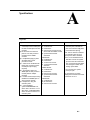
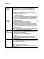
Specifications
A-1
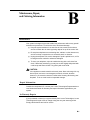
Maintenance, Repair,
and Ordering Information
B-1
■
TOC-vi
Customer Self Service Center on the
Internet
When You Need Help
Power Failure Operation
Battery Replacement
Clearing a Backup-Failure Alarm
Problems with System Phones
Problems with Standard Phones
Other Problems with Phones
Problems with Combination Extensions
Problems with Standard Devices
Problems with Automatic Backup
Problems with Manual Backup
Problems with System Restore
System Problems
Other Problems with System
5-265
5-267
5-268
5-269
5-270
5-272
5-274
5-276
Repair Information
B-1
Contents
■
■
Lucent Technologies Limited Warranty
and Limitation of Liability
Product Ordering Information
Speed Dial Form
■
Speed Dial Form
Programming Mixed Telephone Types
■
Overview
B-2
B-4
C-1
C-1
D-1
D-1
Glossary
GL-1
Index
IN-1
TOC-vii
Contents
TOC-viii
About This Guide
Purpose
This guide is intended for the System Manager. It explains what Releases 1.0,
1.1, and 2.0 of the PARTNER® Advanced Communications System (ACS) can
do, provides instructions for programming and using the system, and tells how to
get the most out of the system’s many features and capabilities. The descriptions
apply to all releases unless specifically identified as features available with
Release 1.1 and Release 2.0 or with Release 2.0 only.
Terminology
Throughout this guide, the PARTNER Advanced Communications System is
referred to simply as the system and Lucent Technologies telephones specifically
designed to work with the system are called system phones. You can also use
industry-standard telephones with the system, which are referred to as standard
phones in this guide. Finally, the PARTNER MAIL VS® or PARTNER MAIL® Voice
Messaging System, which you may have connected to the system, is referred to
as the voice messaging system.
How to Use This Guide
For information about the following topics, refer to the appropriate chapter:
■
Getting Acquainted. Chapter 1 provides an overview of system features
and hardware components.
■
Programming the System. You can change your system’s settings easily
to accommodate new or expanding needs. Chapter 2 provides general
programming information, while Chapter 5 provides detailed instructions
for programming specific system features.
■
Training Co-Workers. Chapter 3 explains how system and standard
phones work with the system. To help train co-workers on telephone
basics, you can share this information with them.
ix
About This Guide
■
Using Auxiliary Equipment. The system supports a wide variety of
auxiliary equipment, including fax machines, modems, voice messaging
systems, and call reporting devices. Chapter 4 provides advice on setting
up these devices to work effectively with the system.
■
Daily Operation. Depending on how your system is set up, you may need
to oversee some of the system’s daily operations. For example, you may
need to turn on Night Service at the end of each day before leaving the
office. Reference information about all features, including descriptions and
instructions for using each feature, is provided in Chapter 5.
■
Solving Problems. Chapter 6 provides information about solving
problems if your system or telephones malfunction.
Once you are experienced with the system, use the Table of Contents or Index to
locate the information you need.
Throughout this guide, feature names are printed in bold—for example, System
Date (#101). Chapter 5, "Feature Reference" provides comprehensive
information about each feature, with the features arranged in alphabetical order.
For example, if you see a reference to System Date (#101), you can look it up in
Chapter 5 for details.
Product Safety Statements
Product safety statements are identified in this guide by a:
! .
! CAUTION:
Indicates the presence of a hazard that will or can cause minor personal
injury or property damage if the hazard is not avoided.
! WARNING:
Indicates the presence of a hazard that can cause severe or fatal personal
injury if the hazard is not avoided.
How to Comment on This Guide
A feedback form is located at the end of this guide, after the appendixes. If the
form is missing, send your comments and recommendations for changes to
Publications Manager, Lucent Technologies, 211 Mount Airy Road (Room
2W-226), Basking Ridge, NJ 07920 (FAX 1 908 953-6912).
x
Overview
1
Features and Capabilities
The following list provides an overview of the system’s features. The features
apply to all releases of PARTNER® ACS unless specified otherwise.
■
Full line of system phones, some with displays showing date, time, and
programming and feedback messages. All system phones provide access
to multiple outside lines and system features.
■
Programmable buttons on system phones, providing one-touch access to
system features simply by pressing the button.
■
Intuitive operation of basic call handling capabilities including transfer,
conference, and hold.
■
Intercom (inside) calling to other system extensions using an Intercom
button and the two-digit number assigned to the extension. Users can
either ring or voice signal an idle system phone; use Voice Interrupt On
Busy to signal another user who is active on a call; or manually signal to
audibly alert another predetermined extension.
■
Grouping of extensions for flexibility in directing and answering calls.
■
Integrated voice messaging support with the PARTNER MAIL VS system
or PARTNER MAIL system, so callers can reach a desired extension or
group without operator assistance and leave messages at unanswered or
busy extensions.
■
PARTNER Voice Messaging PC Card provides a voice messaging service
as well as effective solutions for after-hours call answering and back-up for
the receptionist. (Available with Release 1.1 or later.)
■
Caller ID support on system display phones (if Caller ID service is available
from your local telephone company and you subscribe to it).
■
Power failure operation with standard phones, allowing you to make and
receive calls during a power failure while retaining programmed equipment
settings for up to four days. (An optional Uninterruptible Power Supply, or
UPS, is also available to allow full equipment operation during a power
failure.)
■
Centrex or PBX operation support—including one-touch dialing of feature
access codes on system phones.
1-1
Overview
■
Flexible dialing restrictions and permissions so you can control telephone
activity and phone bills.
■
Special hospitality features that let Bed-and-Breakfast proprietors, for
example, regulate phone use in guest rooms and schedule wake-up calls
for guests.
■
Easy-to-use programming procedures, making it simple for you to manage
your system and telephones. System display phones provide messages
and prompts during programming.
■
Two system-programming extensions, allowing you to program the system
from one extension without interrupting call activity at the other
programming extension—usually the receptionist’s extension.
■
Modular connections to the control unit, making it easy to reconfigure your
system or to add lines and/or extensions as your business grows.
■
Direct connections for industry-standard devices—including most standard
phones, fax machines, answering machines, modems, and credit card
scanners.
■
Optional equipment support, including doorphones, Contact Closure
Adjunct (for example, to release a door lock), loudspeaker paging systems,
music on hold1, call reporting (often referred to as Station Message Detail
Recording (SMDR) devices, auto attendants, extra alerts, and PC Cards
for Backup/Restore or for software upgrades.
Features Available with Release 2.0 or Later
1.
1-2
■
Automatic System Answer feature to help answer and route calls.
■
Direct Extension Dial feature to allow callers to dial an extension or help
group directly without the aid of the receptionist.
■
Line Pooling to create up to four groups, or pools, of multiple outside lines.
When users access a pool to make a call, the system selects an available
line from the pool.
■
Call Coverage for users who are unable to answer their calls, but want their
calls answered by another individual.
■
Caller ID Logging and Dialing feature for users to view the names and
numbers of logged calls from system phones. Users can press the Dial
option to automatically dial the caller’s number.
■
SMDR Talk Time to allow you to track on an SMDR call report the length of
time that users talk on incoming outside calls.
The performance of music over telephone lines is a public performance under United
States Copyright law. Accordingly, in order for the performance of that music to be lawful, it
must be licensed annually to the user by the copyright owners or their representatives. One
way to obtain permission is to contact ASCAP, BMI, and/or similar performing rights
organizations, to obtain a license. Or, you can purchase a Magic on Hold® system, which
includes the required license for the first year. This license must be renewed annually by
the copyright owners or their representatives.
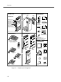
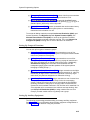
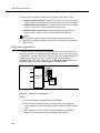
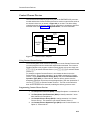
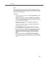
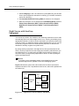
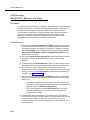
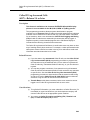
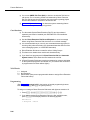
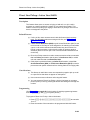
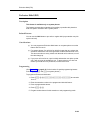
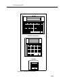
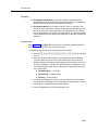
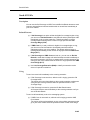
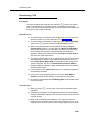
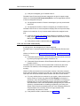
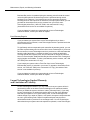
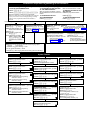
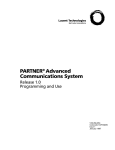
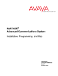
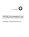
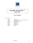
System Components
System Components
Modular hardware design makes the system easy to install and expand. The basic
system consists of a PARTNER ACS processor module, which supports three
lines and eight extensions. Using these lines and extensions, you can add various
optional devices and telephones to configure your system to meet your needs. To
expand the system to include more lines and extensions, simply attach additional
modules and a carrier to contain them. The term control unit is used to refer to the
standalone PARTNER ACS processor module (or to the carrier and the modules it
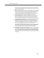
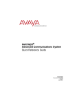
contains), since this is the heart of the system. Figure 1-1 shows an example of
system components.
! WARNING:
There are no customer-serviceable components inside the system modules
or carrier. There are hazardous voltages within that can cause severe or
fatal personal injury. DO NOT OPEN THE MODULES.
1-3
Overview
Optional Carriers
CONTROL UNIT
Optional Devices
5-Slot
Carrier
PARTNER ACS
Processor Module
2-Slot
Carrier
(for the control unit)
PARTNER
Grounding Screw
Serial Printer
PARTNER
3000
Contact Closure Jack
SMDR Jack
PC Card Slots (2)
Power LED
PAGE Jack
Paging System
PARTNER
MAIL VS
Voice Messaging
System
Outside Line Jacks (3)
MUSIC ON HOLD Jack
(for RCA phono plug)
Extension Jacks (8)
Call Accounting
Terminal (Basic or Plus)
Battery Compartment
ER 3000 t
PARTN e Adjunc
t Closur
Contac
PUSH
Contact Closure
Adjunct
POWER PLAY RECORD
Optional Modules
SYSTEM PHONES
Magic on Hold deck
Inter
PC Cards
• Backup/Restore
• ASA/DXD (R2.0 or later)
• Software upgrade (R2.0 or later)
• PARTNER Voice Messaging
com
Inter
com
Ext
.
Featu
re
Conf
Mic
HFAI
ABC
2
GHI
4
PARTNER
DEF
3
JKL
PQRS
Hold
PARTNER
Mes
sage
1
Trans
fr
Spkr
5
7
MNO
6
TUV
8
*
WXYZ
9
0
#
PARTNER-34D® Phone
(with optional PARTNER-CA48
Intercom Autodialer)
PFT
PFT
Optional Devices
L
I
L
N
I
E
N
(for extension jacks)
S
E
S
400
MODULE
206
R1.0
MODULE
PFT
On/Off
Feat/P
Conf
Trans
Redial
Mute
1
2 ABC 3 DEF
4 GHI 5 JKL
6 MNO
7PQRS
E
X
T
8 TUV 9 WXYZ
E
Hold
0 OPER
N
S
PFT
I
O
SPARE
L
I
HANDSET
N
N
REFRESH
S
E
S
TransTalk™
Wireless
Phones
Inte
Inte
rcom
Ext
Feat
ure
.
Mes
1
ABC
Tran
sfr
Standard
Touch-Tone
Phone
sag
e
2
GHI
4
DEF
3
JKL
PQR
S
Hold
400
Module
206
Module
rcom
Con
f
Mic
HFA
I
Spkr
PARTNER MAIL
Voice Messaging
System
5
7
MNO
6
TUV
8
*
WXY
9
0
Z
#
PARTNER-18D®
Phone
PARTNER
3000
Inte
Ext
Answering
Machine
rcom
.
Inte
rcom
Mes
sag
e
Feat
ure
Spkr
Con
f
Mic
HFA
I
Tran
sfr
1
Hold
ABC
2
GHI
4
Fax Machine
DEF
3
JKL
PQR
S
5
7
MNO
6
TUV
*
8
WXY
Z
9
0
#
PARTNER-6®
Phone
PUSH
Alert
com
com
Ext
.
Mes
sage
POWER
1
ABC
2
GHI
4
PRIMARY EXT.
9
LINE
SECONDARY EXT.
WXYZ
TELEPHONE
MNO
6
TUV
8
0
LINE
5
7
TELEPHONE
DEF
3
JKL
PQRS
*
POWER
R-RAU
DTMF
#
PARTNER-18®
Phone
Figure 1-1.
1-4
308EC
Module
Sample System Components
CU-RAU PULSE
Inter
Featu
re
Conf
Trans
fr
Hold
ACTIVE
Inter
Mic
HFAI
Spkr
Doorphone
Remote
Administration
Unit
PassageWay
Adapter
System Components
Configurations
The system can have one of three basic configurations, all of which must be
wall-mounted:
■
standalone PARTNER ACS processor module. This configuration does not
use a carrier.
■
2-Slot carrier, which can hold up to two modules. The PARTNER ACS
processor module resides in the leftmost slot.
■
5-Slot carrier, which can hold up to five modules. The PARTNER ACS
processor module resides in the center slot. This carrier includes a cover.
In either carrier, one and only one of the modules must be a PARTNER ACS
processor module. The modules slide into the carrier, which channels power to
the system.
System Modules
The following system modules can be installed in your system:
■
PARTNER ACS Processor Module provides the software intelligence that
controls the system’s features. It has jacks for three outside lines, eight
extensions, a music-on-hold audio source, a loudspeaker paging system, a
grounding screw, a Contact Closure Adjunct, and a call reporting (SMDR)
device, such as a printer. It also has two PC Card slots, a bicolor red and
green light-emitting diode (LED), and two AAA user-replaceable batteries.
The module also provides support for Caller ID information on system
display phones. The system requires one PARTNER ACS processor
module.
■
200 Module has two outside line jacks, but no extension jacks. This
module is an inexpensive way to add lines when you do not need more
extensions.
■
206E Module has jacks to connect a maximum of two outside telephone
lines and six extensions to the system. You can connect telephones and
other telecommunications devices (such as fax machines and modems) to
the extension jacks (either directly or through your building’s modular wall
jacks). Each 206E module has a green power indicator that shows it is
receiving power.
■
400E Module is similar to the 206EC module but without extension jacks. It
has four outside line jacks. Like the 200 module, this module is an
inexpensive way to add lines when you do not need more extensions.
■
206EC/400EC Modules provide the same capabilities as the 206E and
400E modules, respectively, but add support for Caller ID information on
system display phones. To get Caller ID, first you must subscribe to the
service from your local phone company (if it is available) on a per-line
basis, then connect those lines associated with Caller ID to the line jacks
1-5
Overview
on the 206EC and/or 400EC modules. Any users with system display
phones who receive calls on Caller ID lines will get Caller ID. For more
information, see "Caller ID" on page 5-58.
■
308EC Expansion Module (Release 2.0 or later) provides expanded line
and extension capability. It has jacks for three outside lines and eight
extensions. Using combinations of modules, you can have a maximum of
40 extensions with 15 lines (one ACS processor module and four 308EC
modules) or 19 lines with eight extensions (one ACS processor module
and four 400 modules). To get Caller ID, first you must subscribe to the
service from your local phone company (if it is available) on a per-line
basis, then connect those lines associated with Caller ID to the line jacks
on the 206EC, 308EC, and/or 400EC modules. Any users with system
display phones who receive calls on Caller ID lines will get Caller ID. For
more information, see "Caller ID" on page 5-58.
Hereafter, references to 206 modules include 206E, 206EC, and all 206 modules
used with previous releases of the PARTNER product line. Similarly, references to
400 modules include 400E, 400EC, and all 400 modules used with previous
releases of the PARTNER product line. Any 200 modules can also be used.
If you want message-waiting capability on standard phones that are equipped with
LED-compatible message-waiting lights, you must connect those phones to
extension jacks on a PARTNER ACS processor module, a 308EC module, or on
Release 3.1 (R3.1) or later 206 modules.
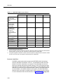
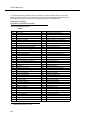
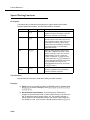
Table 1-1.
Summary of Module Capacities
Module
Lines
Extensions
308EC
3
8
200
2
0
206
2
6
400
4
0
ACS
3
8
NOTE:
Extension numbering is done dynamically. That is, when numbering
extensions, the 200, 400, and PARTNER MAIL VS modules count as six
extensions.
System Batteries
The system uses two user-replaceable AAA-size standard alkaline batteries in the
PARTNER ACS processor module to ensure that system programming and
telephone programming settings are not lost in case of a power failure. See
"Troubleshooting" on Chapter 6 for instructions for replacing the batteries.
1-6
System Components
PC Card Slots
The PARTNER ACS processor module has two PCMCIA (Personal Computer
Memory Card International Association) interface slots (hereafter referred to as
PC Card slots). You can buy PC Cards to use in these slots for the following
purposes:
■
Use a Backup and Restore PC Card to backup or restore telephone and
system programming.
■
Upgrade from PARTNER ACS Release 1.0 to Release 1.1 or Release 2.0
or later using a PC Upgrade card. After powering down the system, you
insert the PC Upgrade Card and turn the power back on. While the system
upgrades, the bicolor (red/green) power LED on the processor flashes
green and red alternately. When the upgrade is finished (in about 20
seconds), the power LED becomes steady green. All of your system and
extension programming will be saved and ready to work with the new
release.
■
Use a PC Card to store Automatic System Answer and Direct Extension
Dial messages. You can insert the card in either PC Card Slot 1 or PC Card
Slot 2 of the ACS Processor Module Release 2.0 or later.
■
For Release 1.1 and 2.0 or later, use a PARTNER Voice Messaging PC
Card to provide messaging features (store personal greeting and store and
retrieve callers’ messages) for up to four mailboxes.
For information on installing PC Cards, see PARTNER PC Card Installation
Instructions.
System Capacity
The PARTNER ACS release you have, the carrier you use and the combination of
modules installed determine the number of available lines and extensions:
■
For PARTNER ACS Release 1.0 and 1.1, the carrier you use and the
combination of 206 and 400 modules installed determine the number of
available lines and extensions. The system allows up to 15 lines and up to
32 extensions; however, these maximums cannot be achieved
simultaneously.
1-7
Overview
Table 1-2.
Configurations for Maximum Lines or Maximum Extensions for Release 1.0
and Release 1.1
Configuration
Maximum Lines
Maximum Extensions
standalone
PARTNER ACS processor module
(Total = 3 lines, 8 extensions)
PARTNER ACS processor module
(Total = 8 extensions, 3 lines)
2-Slot Carrier
One PARTNER ACS processor module
One 400 module
(Total = 7 lines, 8 extensions)
One PARTNER ACS processor
module One 206 module
(Total = 14 extensions, 5 lines)
5-Slot Carrier
One PARTNER ACS processor module
Two 206 modules
Two 400 modules
(Total = 15 lines, 20 extensions)
One PARTNER ACS processor
module
Four 206 modules
(Total = 32 extensions, 11 lines)
■
Table 1-3.
For PARTNER ACS Release 2.0, the system allows up to 19 lines and up
to 40 extensions; however, these maximums cannot be achieved
simultaneously.
Configurations for Maximum Lines or Maximum Extensions for Release 2.0
Configuration
Maximum Lines
Maximum Extensions
Standalone
PARTNER ACS processor module
(Total = 3 lines, 8 extensions)
PARTNER ACS processor module
(Total = 8 extensions, 3 lines)
2-Slot Carrier
One PARTNER ACS processor module
One 400 module
(Total = 7 lines, 8 extensions)
One PARTNER ACS processor
module One 308EC module
(Total = 16 extensions, 6 lines)
5-Slot Carrier
One PARTNER ACS processor module
Four 400 modules
(Total = 19 lines, 8 extensions)
One PARTNER ACS processor
module Four 308EC modules
(Total = 40 extensions, 15 lines)
NOTE:
If you want to install a VS module, keep in mind that it will require one of the
slots in the carrier, which reduces the system line and extension capacity.
System Mode
The system supports two modes of operation. The mode of operation determines
how users access outside lines from their phones:
1-8
■
Key Mode. Users access individual outside lines to make and receive
calls.
■
Hybrid Mode. Users can access individual outside lines as in Key mode.
However, you also can create up to four groups, or pools, of multiple
outside lines. When the user accesses a pool to make a call, the system
System Components
selects an available line from the pool. Since multiple lines are associated
with the pool, the user does not know which line within the pool is being
used to make the call.
System mode is determined by the configuration of the processor module. By
default, the system is configured for Key mode. Changing to Hybrid mode requires
modifying the processor module. Only Lucent Technologies Authorized Personnel
can modify the processor module to accommodate Hybrid mode.
The mode for your system must be decided upon before installation; and in the
continental U.S., the mode must be registered with the Federal Communications
Commission (FCC) (see ‘‘FCC Registration’’ later in this section).
Key Mode
When the system operates in Key mode, individual outside lines are assigned to
users’ extensions for making and receiving calls. At extensions with system
phones, each individual line (Line 1, Line 2, Line 3, etc.) assigned to the extension
is represented by its own line button. Users can press any of the available line
buttons on their system phones to make outside calls. (Standard phone users
must dial 9 at intercom dial tone to make an outside call since their phones do not
have line buttons.)
Key mode enables users to easily join calls since each line button can be labeled
using a unique line number. For example, if you are requested to join a call on
Line 2, you simply press the line button labeled “Line 2.” Key mode also lets users
monitor call activity using the lights next to the line button — everyone who has a
specific line assigned to their extension can tell when an incoming call is ringing
on that line, when a call on that line is on hold, and when that line is in use.
At installation, the system assigns outside lines to the buttons on all system
phones from left to right, starting with the bottom row of buttons. On an extension
basis, you can change which lines are assigned and which buttons are used to
select the lines, if desired.
All extensions in a system configured for Key mode are referred to as key
extensions.
Hybrid Mode
Hybrid mode offers users flexibility in accessing outside lines from their phones.
As in Key mode, individual lines can be assigned to system extensions.
Additionally, multiple outside lines can be grouped together in pools. The system
can have up to four pools, including a main pool and three auxiliary pools. Each
pool is identified by a pool access code — 880, 881, 882, and 883 respectively.
Pools are represented on system phones by pool buttons. Unlike line buttons,
pool buttons give users access to multiple lines from a single button. Each
auxiliary pool is associated with only one pool button. Since the main pool
typically contains most of your company’s outside lines, it is associated with two
pool buttons. This setup allows the user to place a call using one of the main pool
1-9
Overview
buttons, put that call on hold, and make another call using the second main pool
button. Or, the user can establish a conference call using lines in the main pool.
The main pool and each auxiliary pool can be assigned to an extension, for a
maximum of five pool buttons.
System phone users can press any of the available pool buttons on their phones
or they can enter the pool access code at intercom dial tone to make an outside
call. (Standard phone users must dial 9 or enter the pool access code at intercom
dial tone to access a pool since their phones do not have pool buttons.) After the
user presses a pool button or enters a pool access code, the system selects a
free line from the pool for the user to make the call. A user can access a pool as
long as there is at least one available line in the pool.
A major benefit of Hybrid mode is that it allows users who have system phones
with fewer buttons to have access to multiple outside lines and various types of
pools. You can make efficient use of outside lines by grouping those of a similar
type or function together. For example, you can create an auxiliary pool of WATS
or international lines and assign the pools to different groups of users.
Additionally, individual lines can be assigned to a manager’s extension so that he
or she always has access to an outside line.
In Hybrid mode, extension 10 always operates like an extension in Key mode.
This means that every outside line in the system is associated with a specific line
button at extension 10.
All other extensions can be set up with access to only lines, only pools, or a
combination of lines and pools:
■
Those extensions that have pool buttons, even if they also have individual
line buttons, are called pooled extensions.
■
Those extensions that have only line buttons (including extension 10) are
called key extensions. Key extensions cannot access pools.
If your system is configured for Hybrid mode, keep in mind:
■
A line can be assigned to only one pool.
■
Individual extensions can be restricted access to specific pools.
■
Individual lines can be assigned to an extension with pool buttons as long
as the lines are not part of any pool.
At installation, the system assigns all outside lines to the main pool and assigns
the main pool to the two leftmost buttons on the bottom row of all system phones,
except extension 10. If desired, you can remove some of the lines from the main
pool and create auxiliary pools. Then you can assign pools and/or individual lines
on a per extension basis.
1-10
System Components
FCC Registration
In the continental U.S., your system’s mode of operation must be registered with
the FCC as either KF (Key Function) for Key or MF (Multifunction) for Hybrid. If
the system is registered as KF, no outside lines can be pooled; if the system is
registered as MF, lines can be pooled and individual lines also can be assigned
directly to line buttons.
Telephones
System Telephones
This guide refers to Lucent Technologies telephones specifically designed to work
with the system as system phones. These include the PARTNER-34D,
PARTNER-18D, PARTNER-18, and PARTNER-6 telephones. You can also use
MLS-34D, MLS-18D, MLS-12D, MLS-12, MLS-6, MLC-6, and the TransTalk©
9000-series wireless phones, including MDW 9000, MDW 9010, and MDW 9030P
Pocketphone, although they are not discussed in this guide. For information about
an MLS-model, MLC-model, or TransTalk 9000-series phone, refer to the
documentation that came with the phone.
System phones have several buttons in common: volume control buttons and the
f, C, A, h,! and S buttons. In addition, each phone has
programmable buttons that can be used for outside lines, pools, extension
numbers, outside phone numbers, or system features. Outside lines and pools, as
well as some system features, require buttons with status lights. Programmable
buttons without lines or pools assigned to them can be programmed with numbers
or features, so you can use the feature or dial the number with one touch. The
number in each PARTNER-model name indicates the number of programmable
buttons with status lights and two i buttons.
If the PARTNER-model phone has a display, indicated by a “D” in the model
name, users receive messages and prompts when making calls and when
programming. (More information about the display is provided in Chapter 5.) A
system display phone is required for system programming.
Valid system extensions depend on which release of PARTNER ACS you have.
Release 1.X extensions are 10 - 41. Release 2.x extensions are 10 - 49.
Throughout this guide, all references to “system extensions” are within these
release-dependent ranges.
Valid system lines also depend on which release of PARTNER ACS you are
using. With System 1.X system line capacities are 01 to 15. With Release 2.0 or
later, system line capacities are 01 to 19. Throughout this guide all references to
“system lines” are within these release-dependent ranges.
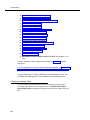
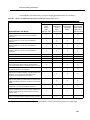
Table 1-4 summarizes PARTNER-model system phone features.
1-11
Overview
Table 1-4.
PARTNER-Model System Phones
PARTNER-34D
PARTNER-18D
PARTNER-18
PARTNER-6
Total Number of
Programmable
Buttons with Status
Lights
32
16
16
4
Total Number of
Programmable
Buttons without
Status Lights
4
4
0
0
Key Mode Line
Button Capacity
(Number of
Programmable
Buttons with Status
Lights)
24
16
16
4
Hybrid Mode Pool
Button Capacity1
5
5
5
4
Line Capacity
192
163
163
4
Intercom Buttons
2
2
2
2
Display
✔
✔
—
—
Speakerphone
✔
✔
✔
✔
1.
2.
3.
The main pool uses two buttons.
Since the system supports a maximum of 19 lines, when the system is configured for the maximum
number of lines, you can use up to 19 buttons on these phones for outside lines.
The system supports a maximum of 19 lines; when the system is configured for the maximum number
of lines, you can use up to 16 buttons on these phones for outside lines.
Intercom Autodialers
PARTNER-model system phones support the PARTNER-CA48 Call Assistant
Intercom Autodialer at extensions 10 and 11. The autodialer provides Auto Dial
buttons for all of the extensions in your system. The status lights next to each
button also indicate calling activity at that extension. Users can program the Auto
Dial buttons for either intercom ringing, voice signaling, or manual signaling. (Note
that each user can have only one Auto Dial button—either on the system phone or
on the autodialer—for another extension in the system.) The Auto Dial buttons
allow the user to dial, signal, or transfer calls to system extensions with one touch.
For more information about Auto Dial buttons, see "Auto Dialing" on page 5-16.
1-12
Auxiliary Equipment
Standard Telephones
You can also use industry-standard single-line rotary or touch-tone telephones,
including feature phones with built-in feature buttons and lights, with the system.
This guide refers to such telephones as standard phones. Lucent
Technologies-certified standard phones are recommended.
The following Lucent Technologies phones can make use of the system’s
message-waiting capability:
■
2500 YMGL Single-Line Analog Telephone Set
■
8101 Analog Telephone
■
8101M Analog Telephone (This model is recommended.)
■
8102 Analog Telephone
■
8110 Analog Telephone
■
7102 Plus Analog Voice Terminal
Check with your local Lucent Technologies Representative or local Authorized
Dealer to find out whether other standard phones with message-waiting lights will
work.
NOTE:
For message waiting capability, you must connect standard phones with
LED-compatible message-waiting lights to a PARTNER ACS processor
module, 308EC module, or to Release 3.1 (R3.1) or later 206 modules. This
message-waiting capability does not work with standard phones with
neon-type message-waiting lights.
Auxiliary Equipment
You can connect many types of telecommunications devices to your system
without expensive adapters or additional phone lines—for example, answering
machines, credit card scanners, and fax machines. Many industry-standard,
single-line devices will work with the system regardless of the manufacturer.
For more information, refer to the list in Chapter 4 or contact your Lucent
Technologies Representative or local Authorized Dealer. Also, see Chapter 4 for
advice on setting up auxiliary equipment to work effectively with the system.
1-13
Overview
Requirements
An industry-standard device must meet the following conditions:
■
■
■
It must be nonproprietary. That is, it cannot be made specifically for use on
a particular telephone system. (For example, you cannot connect a Lucent
Technologies MERLIN LEGEND® Communication System phone,
because it is specifically designed for use on a MERLIN LEGEND
Communication System.)
Its Ringer Equivalence Number (REN1) cannot be greater than 2.0. (The
REN is shown on a label on the device, usually on the bottom.)
You can connect a standard two-line device to the system, but for best
results it should be installed and used as if it were a single-line device.
Connecting Standard Devices
You can connect a standard device so that it is on an extension by itself, or so that
it shares an extension with another piece of equipment (either another standard
device or a system phone) as long as the REN of the two devices together does
not exceed 2.0. (System phones have 0.0 REN.) For example, you can connect a
standard phone and an answering machine to the same extension. An extension
with two devices connected to it is called a combination extension. You cannot
connect two system phones on one extension. The PARTNER Advanced
Communications System Installation guide provides installation instructions.
1.
1-14
REN is a measure of the power it takes to ring a phone. The typical home phone line
supports 4.0–5.0 RENs; each extension jack in your system handles up to 2.0 RENs.
Programming
2
Overview
After the system hardware is installed, you can customize the system and
individual telephones. This chapter explains how to use programming to
accomplish that.
There are two types of programming:
■
System Programming allows you to customize the system to meet the
needs of your business. When the system is first installed, it uses factory
settings that reflect the most commonly used options. You can change
system settings as needed.
You can perform System Programming from either extension 10 or 11.
Because an extension cannot be in programming mode and handle calls at
the same time, consider using extension 11 for programming. Doing so
gives you the ability to program without disrupting call handling by the
receptionist at extension 10.
■
Telephone Programming allows telephones to be customized to meet
individual users’ needs. Individual telephones can be programmed either
from extension 10 or 11 (Centralized Telephone Programming), or from a
user’s extension using a system phone (Extension Programming).
A system display phone is required for System and Centralized Telephone
Programming. If you have any 34-button phones in the system, you must use a
34-button display phone to program since an 18-button phone cannot be used to
program a 34-button phone. Also, if your system has both PARTNER-model and
MLS-model phones, it is recommended that you use a PARTNER-model display
phone at the programming extension.
The system permits programming from a remote location using a Remote
Administration Unit—see ‘‘Remote Programming’’ on page 2-24.
This chapter provides general information about programming procedures. When
a specific feature name is used, it is printed in bold type. For detailed descriptions
2-1
Programming
and step-by-step instructions, refer to that name in Chapter 5. (A Programming
Quick Reference is provided at the end of this book.)
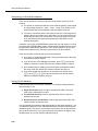
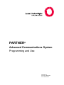
Hardware Considerations
Programming procedures use line and extension numbers. The line number
represents the line jack on a 206, 308EC, or 400 module or an ACS processor
module to which the outside line is connected. Similarly, the extension number
represents the extension jack on a 206 or 308EC module or an ACS processor
module to which the system phone or standard device is connected.
For each 206 module, the system assigns two lines and six extensions; for the
308EC or ACS processor module, the system assigns three lines and eight
extensions; for each 400 module, the system assigns four lines. The system
numbers lines and extensions consecutively from left to right in a 2-Slot carrier,
beginning with the ACS processor module in the leftmost slot; in a 5-Slot carrier,
the numbering also begins with the ACS processor module (in the center slot),
and then moves to the leftmost module and continues consecutively from left to
right.
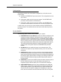
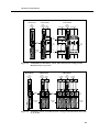
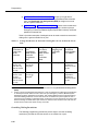
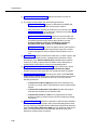
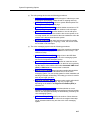
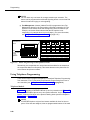
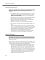
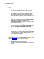
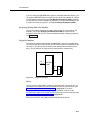
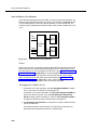
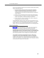
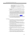
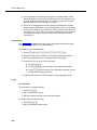
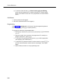
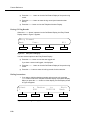
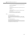
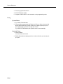
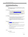
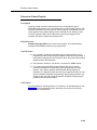
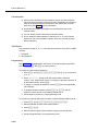
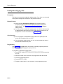
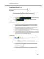
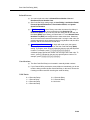
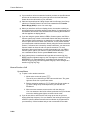
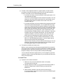
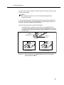
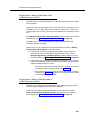
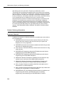
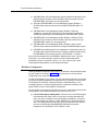
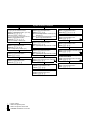
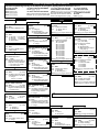
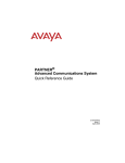
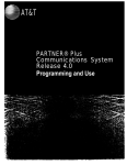
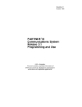
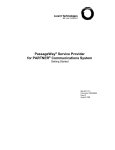
Figure 2-1 shows the numbering scheme for a PARTNER ACS standalone
configuration, for a 2-Slot carrier, and for a 5-Slot carrier, each with the system
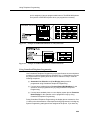
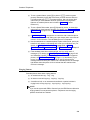
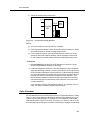
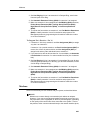
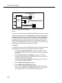
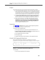
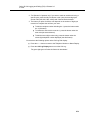
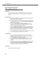
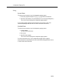
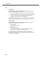
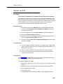
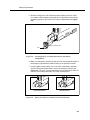
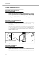
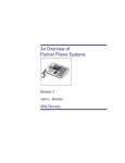
configured for maximum lines. Figure 2-2 shows the numbering scheme for a
PARTNER ACS standalone configuration, for a 2-Slot carrier, and for a 5-Slot
carrier, each with the system configured for maximum extensions. However, your
system can have any number of lines or extensions up to the maximum.
2-2
Hardware Considerations
Stand-Alone
2-Slot Carrier
ACS
Processor
Module
ACS
Processor 400
Module Module
4
5
1
L
4
I
N
E
S
ACS
Processor
Module
400 Modules
Line
Jacks
5
L
8
I
N
E
9
S
L
10
11
12
11
12
Extension
Jacks
12
I
E
13
S
I
E
S
16
17
L
I
N
E
S
2
3
Line
Jacks
Line
Jacks
10
11
12
L
Line
Jacks
6
14
7
15
15
15
16
16
16
17
17
17
I
E
S
7
10
L
13
N
6
L
14
13
L
N
1
2
3
10
400 Modules
N
1
Line
Jacks
2
3
5-Slot Carrier
I
N
E
11
S
I
N
13
14
14
15
E
S
L
I
N
E
S
18
19
L
I
N
E
S
Extension
Jacks
Figure 2-1.
PARTNER ACS Standalone, 2-Slot, and 5-Slot Systems Configured for
Maximum Lines (3, 7, or 19)
Stand-Alone
2-Slot Carrier
ACS
Processor
Module
ACS
Processor 308EC
Module Module
1
2
3
1
4
2
3
5
6
ACS
Processor
Module
2 308EC
Modules
Line
Jacks
2 308EC
Modules
4
7
1
10
13
5
6
8
9
2
3
11
12
14
15
10
10
18
18
26
10
34
42
11
12
11
12
19
20
19
20
27
28
11
12
35
36
43
44
13
21
21
29
13
37
45
14
22
22
30
14
38
46
13
14
Figure 2-2.
Line
Jacks
5-Slot Carrier
Extension
Jacks
Extension
Jacks
15
15
23
23
31
15
39
47
16
16
24
24
32
16
40
48
17
17
25
25
33
17
41
49
Line
Jacks
Extension
Jacks
Standalone, 2-Slot, and 5-Slot Systems Configured for Maximum Extensions
(8, 16, or 40)
2-3
Programming
Initial System Setup
After the control unit is installed, you set up the system using a combination of
system and telephone programming procedures. In this guide, System
Programming procedures are identified by a code (# and three digits); Telephone
Programming procedures are identified by the feature name only.
Use the System Planner as a guide when programming. The following sections
provide an overview of the procedures you use for initial system setup. Chapter 5
explains how to use the specific procedures. Other programming procedures are
optional, but are strongly recommended to make the most of your investment.
(See ‘‘System Programming Options’’ on page 2-11 and ‘‘Telephone
Programming Options’’ on page 2-24 for details.)
Setting the System Clock
After supplying power to the control unit, use the following procedures:
■
System Date (#101) to set the month and day.
■
System Day (#102) to set the day of the week.
■
System Time (#103) to set the hour and minutes.
Assigning Lines
Key Extensions
Use the procedures described in this section to assign individual lines to pooled
extensions or assign lines to key extensions. (In Key mode, all extensions are Key
extensions; in Hybrid mode, extension 10 and any extensions set to Key using
Line Access Mode (#313) are key extensions.)
For initial setup only, use Number of Lines (#104) to specify the number of lines
that will be assigned to all system extensions. Then use the following procedures
as needed:
2-4
■
Dial Mode (#201) to identify any rotary lines (the default for all lines is
“touch-tone”).
■
Line Assignment (#301) to assign lines to specific extensions (if the line
was not assigned using the Number of Lines procedure), to remove lines
from some extensions, or to change the button used to pick up a line at a
specific extension.
■
Line Access Restriction (#302) to prevent an extension from receiving
and/or making outside calls on specific lines.
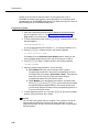
Initial System Setup
■
Line Ringing (Centralized Telephone Programming) to specify when a line
will start ringing at each extension that has the line. For additional
information about line ringing options, see ‘‘Programming a
Receptionist’s Extension’’ on page 2-26.
■
Automatic Line Selection (Centralized Telephone Programming) to
specify the order in which the system selects an available line (intercom or
outside), when a user at the extension lifts the handset or presses S to
make a call without first selecting a specific line button.
For extensions with standard phones, set Automatic Line Selection to
intercom first. This enables standard phones to access system features,
including intercom calling. When users lift the handsets on standard
phones, they hear intercom dial tone. To access an outside line, they must
dial 9.
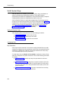
Pooled Extensions
Use the procedures described in this section if your system is configured for
Hybrid mode to change the assignment of lines in pools and to assign auxiliary
pools to or remove the main pool from pooled extensions. If a pooled extension
also has an individual line, refer to ‘‘Key Extensions’’ to assign that individual
line.
For initial setup only, use Number of Lines (#104) to specify the number of lines
that will be assigned to the main pool. Then use the following procedures as
needed:
■
Dial Mode (#201) to identify any rotary lines (the default for all lines is
“touch-tone”).
■
Pool Line Assignment (#207) to remove lines from the main pool and
assign lines to auxiliary pools.
■
Line Access Mode (#313) to change a specific extension’s operation from
Pooled to Key. Refer to ‘‘Key Extensions’’ to assign lines to those
extensions.
■
Pool Extension Assignment (#314) to remove the main pool, assign
auxiliary pools, or change the location of the button used to select an
auxiliary pool at specific extensions. (The location of the two main pool
buttons cannot be changed.)
■
Pool Access Restriction (#315) to prevent an extension from receiving
and/or making outside calls on all lines in specific pools.
■
Line Ringing (Centralized Telephone Programming) to specify when a line
or pool will start ringing at each extension that has the line or pool. By
default, lines are set to Immediate Ring and pools are set to No Ring. For
additional information on line ringing options, see ‘‘Programming a
Receptionist’s Extension’’ on page 2-26.
2-5
Programming
■
Automatic Line Selection (Centralized Telephone Programming) to
specify the order in which the system selects an available line or pool,
when a user at the extension lifts the handset or presses S to make a
call.
For extensions with standard phones, set Automatic Line Selection to
intercom first. This enables standard phones to access equipment
features, including intercom calling. When users lift the handsets on
standard phones, they hear intercom dial tone. To access a pool, they can
dial the pool access code 880, 881, 882, or 883 or dial 9 to access the first
available line or pool in the sequence.
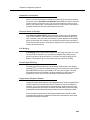
Customizing Extensions
In addition to line or pool assignments, the following procedures can be used to
customize an extension:
2-6
■
Line Coverage Extension (#208) to identify an extension as the “owner”
of a specific outside line. A user at the extension can activate Call
Coverage or VMS Cover for the specified line. Use Call Coverage Rings
(#116) to specify the number of times a call should ring at the owner’s
extension before it is sent to the covering extension or VMS Cover Rings
(#117) to specify the number of times a call should ring at the owner’s
extension before it is sent to the owner’s voice mailbox.
■
Caller ID Call Log Line Association (#318) to select the lines to associate
with extensions for logging unanswered calls. Users can view the Caller ID
information for unanswered calls on the phone’s display panel and autodial
the numbers of the unanswered calls.
■
Display Language (#303) to specify the language (English, French, or
Spanish) for messages that appear on a system display phone.
■
Automatic Extension Privacy (#304) t o prevent other extensions with the
same line from joining a call at the extension. This feature is also useful for
extensions connected to a modem, fax, or any device whose function can
be disrupted by someone trying to join it.
■
Forced Account Code Entry (#307) to prevent the extension from making
an outside call until a required account code is entered. You can also use
Forced Account Code List (#409) to create a list of valid account codes;
this ensures that only authorized users with valid account codes can make
outside calls.
■
Call Waiting (#316) to identify standard phone extensions that can receive
the system (not the local telephone company) call-waiting tone for a
second incoming call when active on a call.
■
Outgoing Call Restriction (#401) to prevent the extension from making
certain types of outgoing calls (on all system lines).
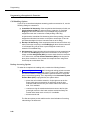
Changing Settings after Installation
■
Disallowed List Assignments (#405) to assign one or more Disallowed
Phone Number Lists to the extension. Use Disallowed Phone Number
Lists (#404) to create the lists of outside numbers that extensions cannot
dial.
■
Allowed List Assignments (#408) to assign one or more Allowed Phone
Number Lists to the extension. Use Allowed Phone Number Lists (#407)
to create the lists of outside numbers that otherwise-restricted extensions
can dial.
■
Pickup Group Extensions (#501), Calling Group Extensions (#502),
Night Service Group Extensions (#504), and Hunt Group Extensions
(#505) to place the extension in any of these groups. See ‘‘Setting Up
Groups of Extensions’’ on page 2-15 for more information.
■
Fax Machine Extensions (#601), Doorphone Extension (#604 and
#605), Doorphone Alert Extensions (#606), AA Extensions (#607),
External Hotline (#311), or Hotline (#603) to identify the extension as one
of these equipment types.
‘‘Setting Up Auxiliary Equipment’’ on page 2-15 provides an overview of
the procedures you use for setting up devices such as voice messaging
systems and call reporting devices. Also, Chapter 4 provides detailed
information and example applications for auxiliary equipment.
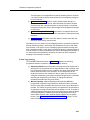
Copy Settings
The recommended way to set up your system is to program one extension for
each type of phone in the system, then use Copy Settings (#399) to program
other phones of the same type. For example, you can program one
PARTNER-18D phone and then copy its settings to any other extensions that
have PARTNER-18D or PARTNER-18 phones. See "Copy Settings (#399)" on
page 5-90 for a list of the programmed settings that are copied.
Changing Settings after Installation
As your business grows or changes, you will probably need to change the way
your system was originally programmed. This section provides some examples
and lists the procedures you would use to change settings after installation. For
specific details on a procedure, refer to the procedure name in Chapter 5.
If you are upgrading to PARTNER A CS Release 1.1 or 2.0 or later from an earlier
release using the PC Card upgrade, all of your system programming settings will
be converted to work with the new release. However, you may want to consider
some additional programming for the features that are new in Release 2.0 or later.
The new programmable features are:
■
Automatic System Answer Button (#111)
■
Automatic System Answer Delay (#110)
2-7
Programming
■
Automatic System Answer Lines (#204)
■
Automatic System Answer Mode (#121)
■
Automatic System Answer Record/Playback (I891)
■
Call Coverage (F20, XX, XX)
■
Call Coverage Rings (#116)
■
Caller ID Call Log Line Association (#318)
■
Caller ID Log Answered Calls (317)
■
Direct Extension Dial Button (#113)
■
Direct Extension Dial Delay (#112)
■
Direct Extension Dial Lines (#205)
■
Direct Extension Dial Record/Playback (I892)
■
Pool Access Restriction (#315)
■
Pool Extension Assignment (#314)
■
Pool Line Assignment (#207)
■
SMDR Talk Time (#611)
■
PARTNER Voice Messaging PC Card (PARTNER ACS Release 1.1 or
later).
For more information about setting these features, see Chapter 5, "Feature
Reference".
For more information on using the PC Card Software Upgrade, see ‘‘Upgrading
from PARTNER ACS Release 1.0 to Release 1.1 or Release 2.0 or Later’’ on
page 2-24 in this section.
For more information on using the PARTNER Voice Messaging PC card, see
PARTNER Voice Messaging PC Card Installation, Programming and Use.
Changing the System Clock
You may need to change the system clock for daylight saving time, after a
prolonged power failure, or after a system reset. Use System Date (#101),
System Day (#102), and System Time (#103) to set the current date, day, and
time.
2-8
Changing Settings after Installation
Adding New Lines
Key Extensions
Use this section to add individual lines to pooled extensions or to add new lines to
key extensions (all extensions in Key mode; in Hybrid mode, extension 10 and
any extensions set to Key using Line Access Mode (#301) are key extensions.)
If you add an outside line to your system, you may need to adjust some line
settings. In particular, use Dial Mode (#201) if the new line is a rotary line, Line
Assignment (#301) to assign the line to specific extensions, Line Ringing
(Centralized Telephone Programming) to specify when the line will start ringing at
each extension that has the line, and Line Access Restriction (#302) to limit an
extension’s access to the line. Additionally, the system automatically assigns the
new line as the last line in the Automatic Line Selection sequence. If you want to
change the order, use Automatic Line Selection (Centralized Telephone
Programming).
IMPORTANT:
Do not use Number of Lines (#104) if you add lines to the system after initial
setup, because it changes Line Assignment (#301), Line Access Restriction
(#302), Automatic Line Selection, and Line Ringing for existing lines back to
factory settings. To add a new line without affecting other settings, use Line
Assignment (#301).
Pooled Extensions
Use this section to add new lines to existing pools if your system is configured for
Hybrid mode. To assign a new line to a pooled extension as an individual line,
follow the procedures in “Key Extensions.”
If you add an outside line to your system for use in an existing pool, use Dial
Mode (#201) if the new line is a rotary line and Pool Line Assignment (#207) t o
add the line to an existing pool.
IMPORTANT:
Do not use Number of Lines (#104) if you add lines to the system after initial
setup, because it changes Pool Line Assignment (#207), Pool Extension
Assignment (#314), Pool Access Restriction (#315), Automatic Line
Selection, and Line Ringing for existing pools back to factory settings.
Additionally, it changes Line Assignment (#301), Line Access Restriction
(#302), Automatic Line Selection, and Line Ringing for individual lines back to
factory settings. To change pool assignments without affecting other settings, use
Pool Line Assignment (#207) and Pool Extension Assignment (#314).
2-9
Programming
Adding New Pools
Use this section if your system is configured for Hybrid mode to create new pools.
If you add outside lines to your system for use in a new pool, use Dial Mode
(#201) if the new lines are rotary lines, Pool Line Assignment (#207) to assign
lines to the new pool, Pool Extension Assignment (#314) to assign the new pool
to specific extensions, Line Ringing (Centralized Telephone Programming) to
specify when the new pool will start ringing at each extension that has the pool,
and Pool Access Restriction (#315) to limit an extension’s access to all the lines
in the new pool. Also use Automatic Line Selection (Centralized Telephone
Programming) to add the new pool to the extension’s Automatic Line Selection
sequence.
Adding New Extensions
If you add an extension to your system, you can probably use Copy Settings
(#399) to copy the settings of an existing extension. If you wish to further adjust a
new extension’s settings, see ‘‘Customizing Extensions’’ on page 2-6.
Swapping Extensions
If a user changes location, but wants to keep the same extension number, you can
make the change easily by changing the connection at the control unit.
For example, if the users at extensions 29 and 32 switch offices, you can
disconnect the modular plugs from those extension jacks in the control unit. Then
reconnect the plug from 32 into extension jack 29 and the plug from 29 into
extension jack 32. Now the users can take their respective phones to their new
locations, keep the same extension numbers, and retain the phones’ programmed
settings.
Changing Settings to Support
PBX or Centrex Services
This section applies only if you use PBX or Centrex services with your system. If it
does not apply, go to the next section, “System Programming Options.”
2-10
■
PBX services are provided by a private telephone switch.
■
Centrex services are provided by your local telephone company from a
Central Office (CO) outside your premises. These services include the
Centrex lines connected to your control unit modules and some set of
features—such as hold, conference, or transfer—that are available on
those lines. Centrex services may be offered in your area under a different
name. For specific Centrex features to be available to you, your company
must subscribe to those features. For specific information about using
Centrex, see the Centrex documentation provided by your local telephone
company.
System Programming Options
Some of the issues you should consider when setting up your system to work
effectively behind a PBX or Centrex system are discussed below. Chapter 5
explains how to use the programming procedures discussed here.
Recall Setting
To set up your equipment to work properly with a PBX or Centrex system, first set
Recall Timer Duration (#107) to match the setting used by your PBX or Centrex
system (usually 800 msec, or “32”). This setting affects the length of a Recall
signal sent by the control unit to access PBX or Centrex services.
Dialing Restrictions
Outgoing Call Restriction (#401) is an equipment restriction intended to limit an
extension’s dialing to “inside calls only” (using the i buttons on system
phones) or to “inside and local calls only” (allowing calls within the PBX or Centrex
system and local calls outside the PBX or Centrex system). However, if users in
your system use a dial-out code (9 on most PBX or Centrex systems) before
dialing numbers outside the PBX or Centrex system, the equipment will not be
able to prevent toll calls for extensions restricted to “inside and local calls only”
(unless you use Disallowed Phone Number Lists (#404) to prevent dialing to
specific classes of numbers).
If your PBX or Centrex system includes dialing restrictions, use those instead of
the equipment restrictions. If you have PBX or Centrex dialing restrictions on a
line and also program equipment restrictions, both the PBX or Centrex system
and equipment restrictions apply. However, equipment dialing permissions will not
override PBX or Centrex system restrictions.
Speed Dial and Auto Dial Numbers
When you program numbers outside the PBX or Centrex system as Speed Dial
and Auto Dial numbers, include the PBX or Centrex system dial-out code (9 on
most systems), followed by one or more pauses, in the stored number.
System Programming Options
This section discusses programming options that involve multiple procedures
(such as dialing restrictions and auxiliary equipment settings), as well as features
that can be used throughout your system (such as Speed Dialing). You can use a
combination of programming procedures to set up your system to operate most
efficiently, taking into account your company’s telephone service, personnel, and
equipment, as well as the special needs of particular departments. This section
lists the procedures you can use; for details on using a particular procedure, refer
to the procedure name in Chapter 5.
2-11
Programming
Speed Dialing
You can program up to 100 frequently dialed phone numbers—such as numbers
for suppliers, repair services, customers—so that all users in the system can dial
them by pressing four buttons: f (or # on a standard phone) plus a
three-digit code. These are called System Speed Dial Numbers.
Dialing Restrictions and Permissions
The system has several procedures for restricting telephone use, and several for
overriding those restrictions. You can use any combination of these procedures to
design a system that meets your needs.
When a user makes a call, the system checks the number dialed against all of the
dialing that apply to the extension making the call. When the number dialed
passes a restriction, the system goes to the next restriction, if necessary. If Star
Code Dial Delay (#410) is active, star codes are also checked against the
restrictions. (Star codes, typically dialed before an outgoing call, provide special
services from the local telephone company Central Office (CO); for example, *
6 7 enables a dialer to block the sending of Caller ID information to the called
party.) When a user dials a star code, the system checks it against the dialing
restrictions to determine whether the code is allowed. If the code is allowed, the
system resets its checking procedure and checks the remaining digits that the
user dialed to make sure the call is permitted. When a number violates a
restriction, the call is stopped and the user hears a reorder tone (fast busy signal).
IMPORTANT:
While procedures that restrict dialing are very effective, absolute protection
against misuse cannot be guaranteed. System phones provide more protection
than standard phones. Therefore, it is strongly recommended that you install
system phones where restricting phone use is important.
Locking an Extension
The system offers a Station Lock feature that lets users enter a four-digit code on
their telephone dialpad to lock their extensions. This helps prevent other users
from making outside calls at those extensions.
Restricting Access to Outside Lines or Pools
A user can access a line or pool either by lifting the handset, pressing the line or
pool button on the phone, or dialing the Direct Line Pickup feature code or a pool
access code. If you do not want a user to access a specific outside line or pool,
you can use Line Access Restriction (#302) or Pool Access Restriction (#315)
to control an extension’s access to a certain line or pool (whether the line or pool
is assigned to the extension or not). Table 2-1 provides examples of settings that
can be used to restrict an extension’s access to specific outside lines or pools.
2-12
System Programming Options
NOTE:
If Forced Account Code Entry (#307) is programmed for an extension, that
extension is required to enter an account code before dialing an outside
number—even those on the Emergency Phone Number List (#406) — on
all of the lines or pools assigned to that extension. If the Forced Account
Code List (#409) contains entries, the system checks the account code
against the list. If the account code is on the list, line or pool access is
allowed; if not, line or pool access is denied.
Table 2-1.
Settings that Restrict an Extension’s Access to a Specific Line
Type of Restrictions or
Permissions for the
Extension
Setting for Line
Assignment (#301) and
Pool Extension
Assignment (#314)
Setting for Line Access
Restriction (#302) and Pool
Access Restriction (#315)
Can receive and place
intercom (inside) calls only
All outside lines and pools “not
assigned”1
“No access” for all lines and
pools
Cannot use a specific outside
line or pool
Outside line or pool “not
assigned”*
“No access” for that line or pool
Can only monitor call activity
and pick up held calls on a
specific line
Outside line “assigned”
“No access” for that line
Can only receive calls on a
specific line or pool
Outside line or pool “assigned”
“Incoming only” for that line or
pool
Can only place outgoing calls
on a specific line
Outside line or pool may be
“assigned”*
Outgoing only for that line or
pool
1.
If a line or pool is not assigned to the extension, a user can use Direct Line Pickup to
access the line or dial the pool access code to access a line in the pool. Emergency
numbers, Marked System Speed Dial numbers, Allowed Phone numbers, and numbers
dialed using the System Password override all dialing restrictions if a user has access to an
outside line or pool to place the call. If Forced Account Code Entry is programmed for an
extension, the user must enter an account code before accessing an outside line or pool. If
there are entries in the Forced Account Code List, the entered account code must match an
entry on that list.
Controlling Calls on Outside Lines
When an extension is allowed access to an outside line or pool, you can use the
following procedures to control calling:
■
Outgoing Call Restriction (#401) defines the type of calls (inside only,
local only, or inside, local, and long-distance) that users can make from all
lines or pools available at an extension. Outgoing Call Restriction Button
(#114) allows the receptionist at extension 10 to quickly change an
extension’s current Outgoing Call Restriction setting.
2-13
Programming
■
Disallowed Phone Number Lists (#404) creates up to eight lists of
numbers that cannot be dialed. After creating Disallowed Phone Number
Lists, use Disallowed List Assignments (#405) to assign one or more
lists to a specific extension.
■
Night Service with System Password (#403) restricts users at extensions
in the Night Service group from dialing outside phone numbers (except
Emergency numbers and Marked System Speed Dial numbers) unless the
password is entered first.
Table 2-2 provides examples of settings that can be used to restrict an extension’s
dialing once it gets an outside line or pool.
Table 2-2.
Settings that Restrict an Extension’s Dialing Once It Gets an Outside Line or
Pool
Type of
Restrictions or
Permissions
for the
Extension
Setting for
Line
Assignment
(#301) or Pool
Extension
Assignment
(314)
Setting for
Line Access
Restriction
(#302) or Pool
Access
Restriction
(#315)
Setting for
Outgoing Call
Restriction
(#401)
Setting for
Disallowed
Phone Number
Lists (#404)1
Can place
intercom and
local calls only
(and can answer
any call)
Outside line or
pool may be
“assigned”2
“No restriction”
“Local only”
Any local
numbers the
extension should
not dial
Can place
intercom, local
and longdistance calls
(and can answer
any call)
Outside line or
pool may be
“assigned”2
“No restriction”
“No restriction”
Any local and
long-distance
numbers the
extension should
not dial
1.
2.
The Disallowed List then must be assigned to the extension using Disallowed List Assignment
(#405).
If a line or pool is not assigned to the extension, a user can use Direct Line Pickup to access the line
or dial the pool access code to access a line in the pool. Emergency numbers, Marked System
Speed Dial numbers, Allowed Phone numbers, and numbers dialed using the System Password
override all dialing restrictions if a user has access to an outside line or pool to place the call. If
Forced Account Code Entry is programmed for an extension, the user must enter an account code
before accessing an outside line or pool. If there are entries in the Forced Account Code List, the
entered account code must match an entry on that list.
Overriding Dialing Restrictions
The following programming procedures provide ways to override all dialing
restrictions, provided the user has access to an outside line or pool:
2-14
System Programming Options
■
Emergency Phone Number List (#406) defines a list of up to ten numbers
that can be dialed from any extension. A typical number is 911.
■
Marked System Speed Dial Numbers are specially identified System
Speed Dial numbers, which a user can dial by pressing f (or # on a
standard phone) followed by a three-digit code.
■
System Password (#403) creates a password that can be entered at any
PARTNER-model or MLS-model system phone to override dialing
restrictions for the duration of a call.
To override all dialing restrictions except Line Access Restriction (#302), pool
Access Restriction, and Night Service with System Password (#403), use
Allowed Phone Number Lists (#407) to create up to eight lists of outside
numbers that otherwise-restricted extensions can dial. Then use Allowed List
Assignments (#408) to assign one or more of the lists to an extension.
Setting Up Groups of Extensions
You can set up four types of extension groups:
■
Pickup Group Extensions (#501) assigns extensions to one of four
Pickup Groups. A Pickup Group lets any user in the system answer outside
calls for any extension in that group.
■
Calling Group Extensions (#502) assigns extensions to one of four
Calling Groups. A Calling Group lets users ring or page all extensions in
that group simultaneously or transfer calls into the group. (Additionally,
Simultaneous Paging lets users make announcements over the
loudspeaker paging system and the speakers of idle system phones
belonging to Calling Group 1.)
■
Night Service Group Extensions (#504) assigns extensions to the Night
Service Group. When Night Service is activated at extension 10, calls ring
immediately at Night Service extensions regardless of how they ring at
other times (only the lines assigned to an extension will ring).
■
Hunt Group Extensions (#505) assigns extensions to one of seven Hunt
Groups. (Hunt Group 7 is used exclusively for the voice messaging
system.) A Hunt Group lets users ring or voice signal the first available
(nonbusy) extension in that group. If a ringing call is not answered, the
system tries each available extension in turn until the call is answered. If a
voice-signaled call is not answered, the call does not keep hunting. Also
use Group Call Distribution (#206) to assign outside lines to a Hunt
Group if you want outside calls to ring directly into a group.
Setting Up Auxiliary Equipment
The following programming procedures help you manage auxiliary equipment.
See Chapter 4 for more information about auxiliary equipment configurations or
refer to Chapter 5 for details on using the procedure:
2-15
Programming
■
Fax Machine Extensions (#601) identifies extensions to which fax
machines are connected.
■
The music-on-hold feature uses the following procedures:
— Music on Hold (#602) activates or deactivates the MUSIC ON
HOLD jack on the PARTNER ACS processor module.
— When this jack is activated, an audio source is connected, and Ring
on Transfer (#119) is set to Not Active, callers hear recorded music
or messages while being transferred.
— Music on Hold Volume (#614) controls the volume at which the
music plays when the MUSIC ON HOLD jack is active. Changes to
this setting affect the many features that use Music on Hold:
Background Music, Call Park, Call Waiting, Conference,
Exclusive Hold, Hold, Transfer, and Transfer Return.
— Background Music lets users with system phones (other than the
MDC 9000 or TransTalk 9000-series phones) play the recorded
material through their phone’s speaker when the phone is not in
use.
■
Hotline (#603) identifies internal hotline extensions, so when a person lifts
the handset of the hotline phone, a predetermined extension number
automatically rings. External Hotline (#311) identifies external hotline
extensions, so when a person lifts the handset of the hotline phone, a
predetermined outside phone number is automatically dialed.
■
Doorphone Extension (#604 and #605) identifies extensions to which
doorphones are connected. Doorphone Alert Extensions (#606)
identifies extensions that signal when the doorphone button is pressed.
■
The Contact Closure Adjunct, which plugs into a jack on the PARTNER
ACS processor module and has two Contact Closures that can be used to
control devices such as an electronic door lock or an alert, uses the
following procedures:
— Contact Closure Group (#612) specifies which extensions can
activate one or both of the Contact Closures on the Contact Closure
Adjunct.
— Contact Closure Operation Type (#613) specifies the length of
time that each Contact Closure remains active.
— Contact Closure F41 and F42 can be programmed on feature
buttons so that the Contact Closures can be activated by pressing
the buttons.
■
2-16
AA Extensions (#607) identifies an extension to which an auto attendant
is connected. This lets the system notify users with display phones when
they are receiving a call that has been transferred from the auto attendant.
Also, Transfer Return Extension (#306) lets you identify the extension to
which a call transferred by the auto attendant should be routed if the
destination extension does not answer.
System Programming Options
■
The call reporting device uses the following procedures:
— SMDR Record Type (#608) specifies the type of calls that you want
to record for call reporting—either all calls or outgoing calls only.
— SMDR Top of Page (#609) notifies the system that the printer has
been aligned to the top of a new page.
— SMDR Output Format (#610) identifies whether a maximum of 15
digits or 24 digits is printed for dialed numbers on the call report.
— SMDR Talk Time (#611) specifies whether or not the call report
includes the Talk field, which records the time a user spends on an
incoming outside call—from the time the user answers the call to the
time the call is disconnected from the system.
— Account Code Entry lets users enter account codes for outside
telephone calls (incoming or outgoing); if used, the account codes
are included on the call report.
■
The voice messaging system uses the following procedures:
— Hunt Group Extensions (#505) assigns the extensions associated
with the voice messaging system hardware to Hunt Group 7—the
VMS Hunt Group.
— Group Call Distribution (#206) assigns lines to the VMS Hunt
Group so calls can ring directly into the voice messaging system
and receive Automated Attendant Service.
— Line Coverage Extension (#208) identifies an extension as the
owner of a specific outside line so calls on that line can ring directly
into the owner’s voice mailbox when either Automatic VMS Cover
(#310) or VMS Cover is on at the owner’s extension.
— VMS Hunt Delay (#506) determines when outside calls should be
answered by the Automated Attendant Service of the voice
messaging system. You can set the system for either immediate call
handling or delayed call handling. The setting you select is used for
both day and night operation.
— VMS Hunt Schedule (#507) determines when outside calls should
ring the VMS Hunt Group (always, day only, or night only)
depending on the status of the Night Service Button (#503) at
extension 10.
— Automatic VMS Cover (#310) determines whether or not an
extension’s unanswered intercom and transferred calls and outside
calls on lines assigned ownership are automatically covered by the
voice messaging system.
— VMS Cover Rings (#117) specifies the number of times intercom
and transferred calls or outside calls on lines assigned ownership
ring at extensions before they are sent to the voice messaging
system.
2-17
Programming
— Transfer Return Extension (#306) identifies the extension to which
a call transferred by the voice messaging system should be routed if
the destination extension does not answer and does not have voice
mail coverage active. (The transfer return extension for the voice
messaging system is typically extension 10.)
NOTE:
If an extension has VMS Cover and Call Coverage active, intercom and transferred
calls and outside calls on lines assigned ownership ring at the covering extension after
the specified number of Call Coverage Rings (#116). Then:
■
If the covering extension does not answer, the call is routed after the
specified number of VMS Cover Rings (#117) to the voice mailbox of the
extension that activated Call Coverage.
■
If the covering extension has Do Not Disturb active, the call is immediately
routed to the voice mailbox of the extension that activated Call Coverage.
Backup and Restore Features
The PARTNER ACS processor module has two PC Card slots. These slots
function similarly to a floppy drive on a PC, in that information can be added to the
system or copied from the system using a PC Card inserted in one of the slots. To
use the optional Backup and Restore features of the system, you must purchase a
Backup/Restore PC Card from Lucent Technologies. Only these Lucent
Technologies PC Cards can be used in the PARTNER ACS processor module.
The same PC Card stores both automatic and manual backups separately.
Backup Programming—Automatic (#123) enables you to specify whether
automatic backups should be performed or not. If you set this feature to “Active,”
your system and telephone programming settings are backed up to the PC Card
automatically at 2:00 a.m. on the first day of each month. The PC Card must be
present in the PC Card slot for the backup to take place.
Backup Programming—Manual (#124) enables you to initiate a backup of your
system and telephone programming settings whenever you feel that it is
necessary. It is recommended that a backup be performed after any change to the
system or telephone programming.
Restore Programming (#125) copies either the manual or the automatic backup
data stored on a PC Card back to the system, thereby enabling you to restore
settings to their status at the time of the last automatic or manual backup.
Hospitality Features
The following hospitality feature is for special applications, such as the
Bed-and-Breakfast and Hotel/Motel industries. With this feature, the receptionist
at extension 10 optionally can use the Intercom Autodialer to specify an
extension.
2-18
Using System Programming
■
Outgoing Call Restriction Button (#114) lets you program a button on
the system phone at extension 10 to change an extension’s current
Outgoing Call Restriction setting without entering System Programming
mode. For example, after a guest’s departure, a hotel manager can change
the No Restriction setting of the guest room phone to Inside Only so
outside calls cannot be made from the phone after the guest checks out.
Using System Programming
System Programming changes settings for the system as a whole, or for individual
lines, pools, or extensions. You can also use System Programming to set up
dialing restrictions, define groups, or set up auxiliary equipment. Refer to the
filled-out System Planner when you are changing system settings, and be sure
that any changes in programming are recorded there.
The Programming Overlays
System Programming requires a Programming Overlay placed over the dialpad of
the system display phone at extension 10 or 11. (Overlays are provided with the
system documentation. Replacements can be ordered from the Lucent
Technologies BCS Publications Center. See "Reference Materials" under
"Product Ordering Information" on page B-4.) Figure 2-3 on page 2-21 illustrates
the Programming Overlays for the PARTNER-34D and PARTNER-18D phones.
During System Programming, the normal functions of several buttons on the
display phone at extension 10 or 11 change. For example, the left i button
becomes s and the right i button becomes c. The
Programming Overlay identifies these buttons.
You use the following special buttons while programming:
■
N and P cycle forward and backward through the
programming procedures. You can use these buttons to select a
procedure.
(If a procedure instructs you to press N P, pressing
these buttons one after the other enables you to repeat the current
programming procedure.)
■
n and p cycle forward and backward through a procedure’s
parameters. A parameter is typically an outside line, a pool, an extension,
or a telephone list entry.
■
D and d cycle forward and backward through the valid
entries. These buttons work only for fixed data, such as a line or extension
number. They do not work for variable data such as date, time, password,
telephone numbers, or doorphone assignments.
2-19
Programming
■
r returns the current setting to the factory setting. When using Line
Assignment (#301), removes lines from an extension; when using Pool
Extension Assignment (#314), removes pools from an extension.
■
e ends an entry of variable length, such as a telephone number in an
Allowed Phone Number List.
■
s starts the System Programming process.
c starts the Centralized Telephone Programming process (to
■
customize individual telephones centrally from extension 10 or 11).
2-20
■
f when followed by 0 0, enters or exits programming mode.
■
w enters a “wildcard” (a character that matches any digit dialed) in
telephone numbers in Allowed Phone Number Lists (#407), Disallowed
Phone Number Lists (#404), and the Forced Account Code List (#409).
Using System Programming
System
Program
Next
Procedure
Next
Item
Next
Data
Remove
Prev
Procedure
Prev
Item
Prev
Data
Enter
Central
Tel Program
Message
Feature
Next
Procedure
Next
Item
Next
Data
Remove
Prev
Procedure
Prev
Item
Prev
Data
Enter
Wild
PARTNER–34D
System
Program
Central
Tel Program
Message
Feature
Wild
PARTNER–18D
Figure 2-3.
Programming Overlays for PARTNER-Model Phones
Button Locations
When programming from a PARTNER-model phone at extension 10 or 11, keep in
mind that the button you press at the programming extension may be in a different
location on the phone to which the programming applies. Figure 2-4 on page
2-23 shows the relative location of buttons on each PARTNER-model phone. For
example, the button labeled E on the PARTNER-34D phone in Figure 2-4 is in the
bottom row. The equivalent button on the PARTNER-18D phone is in the leftmost
2-21
Programming
position of the second row from the bottom. If your system has a mix of
PARTNER- and MLS-model phones, refer to Appendix E for information about
programming from a PARTNER-model phone to an MLS-model phone or from an
MLS-model phone to a PARTNER-model phone.
Programming Mode
1. Place the Programming Overlay over the dialpad of the system display
phone at extension 10 or 11—see ‘‘The Programming Overlays’’ on
page 2-19 for more information.
2. To enter programming mode, press f
following appears:
0 0. A display similar to the
PROGRAM EXTENSION 10
(If you are programming from extension 11, “11" displays instead of “10.”)
3. Press s. A display similar to the following appears:
10 Enter Extension Name
This display is for the Extension Name Display feature. When you are
entering System Programming mode, skip it by moving on to Step 4.
4. Press s again. A display similar to the following appears:
SYSTEM PROGRAM
5. Specify a programming procedure in one of two ways:
■
Direct Method: Dial the code for that procedure. System
Programming procedures in this guide are identified by a # and a
three-digit code (for example, System Date is #101). This method is
best when you are using only a few procedures during a
programming session and you know the codes.
■
Cycle Method: Cycle through the procedures in numerical order.
Press N and P to cycle forward and backward
through the programming procedures. This method is best when
you are using multiple procedures during a programming session, or
if you do not know the codes.
6. To exit programming mode, you can press f
off-hook, then place it back in the cradle.
0 0 or lift the handset
NOTE:
You can talk on the phone while you program. This is useful if you call for
support while programming. However, you must call before you enter
programming mode, and you must use the handset to talk, not the speaker
and microphone.
2-22
Using System Programming
PARTNER-34D Phone
Q
R
S
T
M
N
O
P
G
H
I
J
K
L
A
B
C
D
E
F
Ext.
Intercom
Message
Intercom
PARTNER-18D/18 Phone
Q
R
S
T
M
N
O
P
I
J
K
L
E
F
G
H
A
B
C
D
Intercom
Intercom
Ext.
Message
PARTNER-6 Phone
Figure 2-4.
C
D
A
B
Intercom
Intercom
Ext.
Message
Button Locations on PARTNER-Model Phones
2-23
Programming
Changing Programming Type
When you are in programming mode, you can move between System
Programming and Centralized Telephone Programming. To change to Centralized
Telephone Programming when you are in System Programming, press
c. To move back to System Programming when you are in Centralized
Telephone Programming, press c then s.
Remote Programming
The system permits programming from a remote location using an auxiliary device
called the Remote Administration Unit (RAU). Remote programming requires the
installation of two RAUs—one at your site and one at the location from which the
programming is to be done. For more information about remote programming, see
the PARTNER Communications System Remote Administration Unit Installation
and Use guide.
Upgrading from PARTNER
ACS Release 1.0 to Release 1.1 or
Release 2.0 or Later
If you are upgrading to a later release of PARTNER ACS using a PC card, use the
following procedure.
1. Power down the system.
2. Insert the PC Software Upgrade Card into either of the two PC Card slots in
the PARTNER ACS processor module.
3. Turn the system back on. While the system upgrades, the bicolor
(red/green) power LED on the processor flashes green and red alternately.
When the upgrade is finished (in about 20 seconds), the power LED
becomes steady green. All of your system and extension programming
settings will be intact.
Telephone Programming Options
System telephones are ready to use when they are installed, but they can be
customized to meet the needs of your business and individual users. This
customization is accomplished through Telephone Programming.
2-24
Telephone Programming Options
Automatic Line Selection
When a user lifts the telephone’s handset or presses S, the system chooses
an idle line or pool. Automatic Line Selection determines the order in which the
system looks for an idle line or pool. You can set the system to look for lines or
pools in any desired order. For standard phones or for any phone used mainly to
call other extensions, select an inside (intercom) line first.
Extension Name on Display
With Extension Name Display, users can assign a name (up to 20 characters
long) to their extension. Then, when those users make an intercom call, group
call, or transfer a call, their name and extension number appears on the display
phone receiving the call. Similarly, users receiving a transfer return call see the
name and extension number of the person assigned to the extension that did not
answer the transferred call.
Line Ringing
Line Ringing defines when each outside line or pool rings at a phone. For each
line or pool at an extension, you can specify Immediate Ring, Delayed Ring
(phone rings after a 20-second delay), or No Ring. The factory setting for line
buttons is Immediate ring; the factory setting for pool buttons is No Ring.
Personal Speed Dialing
Personal Speed Dial numbers are outside phone numbers that a user dials by
pressing f (or # on a standard phone) plus a two-digit code. Unlike System
Speed Dial numbers, which are available to all users in the system, Personal
Speed Dial numbers are available only at the extension for which they are
programmed. Users can store up to 20 Personal Speed Dial numbers.
Programming Telephone Buttons
Telephone buttons without lines or pools assigned to them can be programmed for
system features such as Exclusive Hold or Conference Drop or for telephone
numbers, so you can use the feature or dial the phone number with one touch.
Once programmed, these buttons are called Auto Dial buttons, because simply
pressing the button automatically dials the feature code or telephone number.
A user who has a system phone with programmable buttons should consider
programming them with a combination of frequently used features and outside
and intercom telephone numbers.
2-25
Programming
Programming a Receptionist’s Extension
Call Handling Options
If you set up a centralized telephone answering position at extension 10, use the
following settings to customize it:
■
Immediate Call Answering. If the receptionist should answer all calls, use
Line Assignment (#301) to assign all lines to extension 10. Set Line
Ringing for all lines at extension 10 to Immediate Ring; set the lines
assigned at each user’s extension to Delayed Ring or No Ring.
In Hybrid mode, Immediate Call Answering is the factory setting. (Lines are
assigned as individual line buttons on the phone at extension 10 and all
pool buttons assigned to users’ extensions are set to No Ring.)
■
Backup Call Answering. If the receptionist should answer some lines only
when a user does not pick up, set Line Ringing for those lines at extension
10 to Delayed Ring; set the lines or pools assigned at each user’s
extension to Immediate Ring.
■
No Answering. If some lines should not be picked up by the receptionist at
all, either set Line Ringing for those lines at extension 10 to No Ring or
simply use Line Assignment (#301) to remove those lines from extension
10. In either case, set Line Access Restriction (#302) to No Access for
those lines at extension 10 to prevent the receptionist from using Direct
Line Pickup to access those lines.
Backup Answering Options
To assist the receptionist in handling calls, consider the following features:
■
Automatic System Answer. Useful during peak calling periods to answer
outside calls while the receptionist is busy on other calls. When activated,
this feature answers incoming calls after a specified number of rings and
plays a customized greeting. Then, depending on how Automatic System
Answer Mode (#121) is programmed, the system either:
— places the call on hold at extension 10 (the light next to the line
button winks green at extension 10 and winks red at all other
extensions that have the line); the outside caller hears music on
hold, if it is available.
— continues to ring all extensions that have access to the line (the
green light next to the line button at those extensions flash); the
outside caller hears music on hold, if it is available.
— disconnects the call.
The first two options provide audible and/or visual indication of incoming
calls waiting to be answered.
2-26
Telephone Programming Options
The third option is not applicable as a backup answering feature; however,
it is useful for making brief announcements such as temporary closings or
hours of business.
■
Direct Extension Dial. Useful for routing outside callers directly to a
specific extension or Hunt Group. When activated, this feature answers
incoming calls after a specified number of rings and plays a customized
message prompting the caller to dial the digits of the designated extension
or hunt group.
■
Call Forwarding/Call Follow-Me. Useful when a receptionist leaves the
desk for any period of time. Calls can be forwarded to a backup answering
extension.
■
Call Coverage. Useful when users are unable to answer their calls and
want them answered by someone else.
Alternatively, you can install a voice messaging system to provide an automated
backup answering position. Useful when the receptionist is busy on calls, away
from the desk, or at night, the voice messaging system answers incoming calls
after a specified number of rings, plays a customized greeting, requests callers to
enter an extension number, and transfers the caller to the appropriate extension. If
no one answers at the destination extension, the caller can leave a personal
message in that extension’s mailbox.
Button Programming
The PARTNER-34D phone shown in Figure 2-5 illustrates the following
programmed buttons in addition to some other system features:
■
Extension Numbers. Auto Dial buttons are programmed for extensions 11
through 28. The receptionist can use these buttons to dial or transfer calls
to the extensions with one touch. In addition, the lights of these Auto Dial
buttons show the status of the extension, so the receptionist can tell
whether the phone at the extension is idle (no lights on), busy (red on),
calling the receptionist (green flash), sending coverage calls to or manually
signaling the receptionist (green flutter), or ringing back after the
receptionist transferred a call (green flutter).
■
Manual Signaling. A Manual Signaling button (labeled MS-Bill) is
programmed to signal the target extension. When the button is pressed,
the user at the target extension will hear a tone for as long as the button is
pressed. This feature is typically used by a receptionist to alert the boss to
an important incoming call when the boss is already on a call. The lights of
a Manual Signaling button work like an Auto Dial button to show the status
of the target extension. Additionally, a Manual Signaling button can be
used to place intercom calls. (Manual Signaling applies only to system
phones.) See "Manual Signaling (F13XX or F13*XX)" on page 5-179 for
more information.
2-27
Programming
NOTE:
You can have only one button for a target extension per extension. The
button can be programmed as a Manual Signaling button or as an Auto Dial
button for intercom ringing or voice signaling.
■
Fax Management. A button (labeled Fax-30) is programmed as a Fax
Management button for the fax machine connected to extension 30. The
lights next to the button show what is happening at the fax machine (for
example, red broken flutter indicates that the fax machine is not
responding—for example when it is out of paper). (For more information,
see "Using the Fax Management Feature" on page 4-15.)
PARTNER-34D
Phone
Line/
Programmable
Buttons
Any unused
line button is
programmable
Figure 2-5.
Ext.
Intercom
Message
Intercom
Button Programming for Receptionist’s Phone
Alternatively, the receptionist can use an Intercom Autodialer for the extensions
the receptionist dials most frequently. This leaves buttons on the phone free for
more features and phone numbers.
Using Telephone Programming
There are two ways to program a telephone: Centralized Telephone Programming
from extension 10 or 11 (see below) and Extension Programming from a user’s
own extension (see ‘‘Using Extension Programming’’ on page 2-31).
Telephone Models
Figure 2-6 illustrates a PARTNER-18D set up as a key extension and Figure 2-7
illustrates a PARTNER-6 phone set up as a pooled extension. As you program
buttons, mark their functions on the phone’s labeling sheet (see the examples in
Figure 2-6 and Figure 2-7).
NOTE:
A PARTNER-6 phone only has four buttons available for lines for lines or
pools. If four lines are assigned, it has no programmable buttons. If the main
2-28
Using Telephone Programming
pool is assigned, it has two programmable buttons. The MDW 9000 phones
look just like a PARTNER-6 phone when you program them centrally.
PARTNER-18D phone
Ext.
Any unused
line button is
programmable
Figure 2-6.
Intercom
Message
Intercom
Example of PARTNER-18D Phone as a Key Extension
PARTNER-6 phone
Figure 2-7.
Intercom
Intercom
Ext.
Message
Example of PARTNER-6 Phone as a Pooled Extension
Using Centralized Telephone Programming
Use Centralized Telephone Programming to program features or store telephone
numbers for individual extensions from extension 10 or 11. Most features also can
be programmed on a system phone at the user’s extension. Keep in mind the
following exceptions:
■
Automatic Line Selection and Line Ringing always must be
programmed using Centralized Telephone Programming.
■
If a user has a standard phone, Personal Speed Dial Numbers for the
extension can be programmed only by using Centralized Telephone
Programming.
■
If a user has a standard phone or a non-display system phone, Extension
Name Display for the extension can be programmed only by using
Centralized Telephone Programming.
During Centralized Telephone Programming, the display phone at extension 10 or
11 takes on the characteristics of the telephone being programmed, including any
System Programming settings and lines assigned to the phone. If you have any
2-29
Programming
34-button phones in the system, you must use a 34-button display phone to
program since an 18-button phone cannot be used to program a 34-button phone.
Also, if your system has both PARTNER-model and MLS-model phones, it is
recommended that you use a PARTNER-model display phone at the
programming extension.
To program a phone from extension 10 or 11, use the following procedure:
1. Place the Programming Overlay over the dialpad of the system display
phone at extension 10 or 11 — see ‘‘The Programming Overlays’’ on
page 2-19 for more information.
2. To start programming:
a. Press f
0 0. A display similar to the following appears:
PROGRAM EXTENSION 10
(If you are programming from extension 11, “11" displays instead of
“10.”)
b. Press s. A display similar to the following appears:
10 Enter Extension Name
This display is for the Extension Name Display feature. When you
are entering Centralized Telephone Programming mode, skip it by
moving on to Step 2c.
c. Press s again. The display reads:
SYSTEM PROGRAM
d. Press c. A display similar to the following appears:
CENTRAL TELEPHONE PROG
Extension:
3. Dial the extension number of the telephone to be programmed.
The green lights next to buttons on which lines or pools are assigned show
the current Line Ringing settings; remaining buttons can be programmed
with telephone numbers, extension numbers, or system features.
4. At this point, you can:
2-30
■
Use Automatic Line Selection to change the order in which the
telephone selects a line or pool when the user picks up the handset.
(If you want to change Automatic Line Selection for an extension,
you must do so immediately after you enter programming mode and
dial the extension number.)
■
Use Extension Name Display to assign a user’s name to the
extension. See Chapter 5 for the character codes. (Like Automatic
Line Selection, this procedure must be done immediately after you
enter programming mode and dial the extension number. If you want
to change both Automatic Line Selection and Extension Name
Using Telephone Programming
Display, first change Automatic Line Selection, then press
c, redial the extension number, then use Extension
Name Display.)
■
Use Line Ringing to change the ringing for an individual line or
pool.
5. Program Personal Speed Dial Numbers, Auto Dial numbers, or system
features as described in Chapter 5.
To erase the current programming from a button, press the button, then
press !.
6. To change the settings for another extension, press c, then dial
the new extension number.
7. To exit programming mode, you can press f
off-hook, then place it back in the cradle.
0 0, or lift the handset
Changing Programming Type
When you are in programming mode, you can move between System
Programming and Centralized Telephone Programming. To change to System
Programming when you are in Centralized Telephone Programming, press
c then s. To move back to Centralized Telephone
Programming when you are in System Programming, press c.
Using Extension Programming
Users can program features or store numbers on buttons from their own phones
using Extension Programming. Keep in mind the following exceptions:
■
Automatic Line Selection and Line Ringing always must be
programmed using Centralized Telephone Programming.
■
If a user has a standard phone, Personal Speed Dial Numbers for the
extension can be programmed only by using Centralized Telephone
Programming.
■
If a user has a standard phone or a non-display system phone, Extension
Name Display for the extension can be programmed only by using
Centralized Telephone Programming.
To program at the extension, use the following procedure:
1. To start programming, dial f 0 0.
The green lights next to buttons on which lines or pools are assigned for
the extension show the current Line Ringing settings. Remaining buttons
can be programmed with telephone numbers, extension numbers, or
system features.
2-31
Programming
2. To assign a name to the extension, press left i, then enter the
character codes. See "Extension Name Display" on page 5-125 for the
codes.
3. Program Personal Speed Dial Numbers, Auto Dial numbers, or system
features as described in Chapter 5.
To erase the current programming from a button, press the button, then
press!.
4. To exit programming mode, you can press f
off-hook, then place it back in the cradle.
2-32
0 0, or lift the handset
Learning About Telephones
3
This chapter explains how system and standard phones work with the system, as
well as combination extensions where more than one phone or standard device is
installed. In addition, basic call handling features and dial-code features are listed
at the end of this chapter. See the feature name in Chapter 5 for details about a
specific feature.
System Telephones
PARTNER-model phones have several buttons and indicators in common. The
following pages explain where they are and how they work. For information about
an MLC-6, MLS-model, or TransTalk 9000-series phone, refer to the
documentation that came with the phone.
3-1
Learning About Telephones
Buttons and Indicators
PARTNER-34D
Display
Programmable Buttons
(4 without lights)
+
–
Feature
Line/Programmable
Buttons (32 with lights)
Conf
Intercom Buttons (2)
Mic/
HFAI
Transfr
Ext.
Intercom
Intercom
+
Spkr
Hold
Message
–
Message Light
Feature
Conf
Mic/
HFAI
Transfr
Spkr
Hold
1
GHI
ABC
DEF
2
3
JKL
MNO
4
5
6
PQRS
TUV
WXYZ
7
8
9
*
0
#
Pull-Out Tray for Quick
Reference Cards
(all PARTNER models)
The following buttons and indicators appear on system phones:
Display. (PARTNER-34D and PARTNER-18D only) Shows date, day, and time when the phone
is idle, number dialed when placing a call, extension number (and name if programmed) calling
you or transferring a call to you, and duration while a call is in progress. When programming,
shows settings, options, and prompts. (To adjust the display contrast, see Volume Control
Buttons on the next page.)
Line/Programmable Buttons. Used for individual outside lines or (if no line is assigned on a
button) for programming telephone or extension numbers, or other system features (such as Last
Number Redial). When a line is assigned, press the line button to make a call on that specific line
(lights show status of line). When a number feature is programmed, press the button to dial the
number or use the feature. The PARTNER-34D has 36 programmable buttons (32 with lights and
4 without lights); the PARTNER-18D has 20 programmable buttons (16 with lights and 4 without
lights); the PARTNER-18 has 16 programmable buttons (all with lights); the PARTNER-6 has 4
programmable buttons (all with lights).
Intercom Buttons. Press to make (or answer) a call to (or form) another extension in the
system.
Feature. Press to change programmed settings or use system features.
Conf. Press to add other parties to your call.
Transfr. Press to pass a call to another extension.
Hold. Press to put a call on hold.
3-2
System Telephones
PARTNER-6
Intercom
Intercom
Ext.
Message
+
–
1
GHI
Feat
Spkr
Conf
Mic/
HFAI
Transfr
Hold
ABC
DEF
2
3
JKL
MNO
4
5
6
PQRS
TUV
WXYZ
7
8
9
*
0
#
Line/Programmable
Buttons (4)
Intercom Buttons (2)
Message Light
+
–
Feat
Spkr
Conf
Mic/
HFAI
Transfr
Hold
PARTNER-18
PARTNER-18D
Display
Programmable Buttons
(4 without lights)
Line/Programmable Buttons
(16 with lights)
Intercom Buttons (2)
Ext.
Intercom
+
–
Feature
Conf
Mic/
HFAI
Transfr
Spkr
Hold
Ext.
Message
Intercom
Intercom
Message Light
ABC
DEF
1
2
3
GHI
JKL
MNO
4
5
6
PQRS
TUV
WXYZ
7
8
9
*
0
#
+
+
–
Feature
Conf
Mic/
HFAI
Transfr
Spkr
Hold
–
Message
Intercom
Feature
Conf
Mic/
HFAI
Transfr
Spkr
Hold
ABC
DEF
1
2
3
GHI
JKL
MNO
4
5
6
PQRS
TUV
WXYZ
7
8
9
*
0
#
Spkr. Press to turn on and off the speaker and microphone (if available), so you can dial and
have a conversation without lifting the handset. The light next to this button shows when the
speaker is turned on.
Mic/HFAI. Press to turn the microphone on and off. The light next to this button shows when the
microphone is turned on. Leave on to use Hands-Free Answer on Intercom (HFAI) feature.
Volume Control Buttons. Press - to decrease or + to increase the volume as follows:
■
To adjust ringer volume, press while the phone is idle and the handset is in the cradle.
■
To adjust speaker volume, press while listening to a call through the speaker.
■
To adjust handset volume, press while listening through the handset.
■
To adjust background music volume, press while listening to music through the
phone’s speaker.
To adjust the display contrast on the PARTNER-34D and PARTNER-18D phones, press * then
- to decrease the brightness or + to increase the brightness, while the phone is idle and the
handset is in the cradle.
3-3
Learning About Telephones
Lights
Each line or pool button has a green light and a red light. The meaning of these
lights varies, depending on whether the button is used to access an outside line or
pool, is programmed with a system feature, or is programmed for Auto Dialing an
extension number (Intercom Auto Dial button). (Auto Dial buttons for fax
extensions show additional information; these “Fax Management” buttons are
described in Chapter 4 . When a phone is in programming mode, the lights show
information about programmed settings; see Chapter 2 for details.)
Table 3-1 shows the meanings of the various light patterns for each possible
button assignment.
Table 3-1.
Light Patterns for System Phones
Intercom Auto
Dial Button
Light Pattern
Line Button
Pool Button
Feature Button
Steady On
Line is in use.
Green means you
are using the line;
red means
someone at
another extension
is using the line.
—
Green means
feature1 is on.
Red means the
extension
programmed on
the button is busy
(making or
answering a call).
Off (steady off)
Line is idle (not
being used).
—
Feature1 is off.
Extension
programmed on
the button is idle
(not being used).
Flash (long on, long off)
A call is ringing
on the line. Green
flash means a call
is ringing at your
extension. Red
flash means a call
is ringing on the
line, but not at
your extension.
—
A user is entering
a four-digit code to
lock or unlock his
or her extension.
Green flash means
someone at the
extension
programmed on
the button is
calling you.
Alternating Red/Green
Flash (red on, green on,
red on, green on)
Alternating green
and red flash
appears at both
extensions in a
joined call, and at
any extension
connected in a
conference call.
—
—
—
3-4
System Telephones
Table 3-1.
Light Patterns for System Phones
Light Pattern
Line Button
Pool Button
Feature Button
Intercom Auto
Dial Button
Wink (long on, short off)
A call on the line
is either on hold
or parked. Green
wink means the
call is on hold or
parked at your
extension. Red
wink means the
call is on hold or
parked at another
extension.
(Anyone who has
the line can
retrieve the held
call.)
Green wink
means the
call is either
on hold or
parked at
your
extension.
(Anyone who
has the line
can retrieve
the held call.)
—
—
Green Flutter (short on,
short off)
A call is on
exclusive hold at
your extension
(and can only be
retrieved from
your extension).
A call on a
line in the
pool is on
exclusive
hold at your
extension
and can be
retrieved only
from your
extension.
Caller ID Inspect is
on, a Wake Up
Service call is
being scheduled
from extension 10.
A call transferred
to the extension
programmed on
the button is now
returning to your
phone or you are
being manually
signaled by the
extension.
Red Broken Flutter (short
on/off, long off)
—
—
—
Fax Management
only— the fax
extension is not
answering calls
(may be out of
paper).
1.
Applies to Caller ID Name Display, Do Not Disturb, Night Service, Outgoing Call Restriction Button, Privacy,
Voice Interrupt on Busy Talk-Back, and VMS Cover, all of which require programming on a button with lights.
Can also apply to Account Code Entry, Background Music, and Call Forwarding/Call Follow-Me, if any of them
are programmed on a button with lights. (For more information about programming these features, see
Chapter 5.)
3-5
Learning About Telephones
Ringing Patterns
System phones have these ringing patterns:
■
An outside call will ring... ring... ring.
■
An intercom call will ring BEEP... ring BEEP... ring BEEP. If you have a
system display phone, the caller’s extension number (and name if
programmed) will show on the display.
■
A transferred call, or an unanswered transferred or parked call that is
ringing back at your extension, will ring BEEP BEEP... ring BEEP BEEP...
ring BEEP BEEP.
NOTE:
If you use the system with PBX or Centrex lines, the PBX/Centrex distinctive
ringing patterns are not passed to phones. Phones use the ringing patterns
described here instead.
Dial Tones
You will encounter two different dial tones when calling with a system phone:
■
Outside dial tone is generated by your local phone company to indicate
that you are connected with an outside line.
■
Intercom dial tone is generated by the system to indicate that you are
connected with an inside line. You hear this dial tone when you are making
an inside, or intercom, call.
To hear the difference between the two types of dial tones on a system phone,
press a line or pool button. The dial tone you hear is an outside dial tone. To hear
an intercom dial tone, press i.
Using the Handset, Speaker, and Microphone
Every PARTNER-model and MLS-model system phone except the MLS-6 has a
speaker and a microphone, which you can turn on by pressing S. In addition,
you can turn just the microphone on and off by pressing!. When the green
light next to! is on, the microphone is on.
If you prefer to dial and conduct calls without lifting the handset, you can use the
speaker and the microphone instead. Use these techniques to make calls with the
speaker and the microphone:
■
3-6
To make a call without lifting the handset, press S to get a dial tone;
then dial the number and you will hear the call ringing. When the other
party answers, you can talk without lifting the handset.
System Telephones
■
If you are already on a call, you can switch from the handset to the speaker
and microphone by pressing S and hanging up the handset.
Conversely, if you are using the speaker and microphone and want to
switch to the handset, lift the handset and the speaker and microphone will
turn off.
■
To turn off the microphone when you are using the speaker, press!.
This will mute your voice so the other party cannot hear you.
■
Use the Hands-Free Answer on Intercom (HFAI) feature to answer
voice-signaled calls without lifting the handset (see below).
Hands-Free Answer on Intercom (HFAI)
When you receive a voice-signaled intercom call, your phone beeps once to
indicate that your speaker has been turned on automatically, and you hear the
caller’s voice over your phone’s speaker. If you leave your microphone on all the
time, you can start talking when you hear the caller, without lifting the handset.
This feature is called Hands-Free Answer on Intercom.
Any user in the system can make a voice-signaled call to an idle system phone by
pressing i* then dialing an extension number or pressing an Auto Dial
button programmed for voice signaling. (You can make a voice-signaled call from
either a system phone or a standard phone. However, if you try to make a
voice-signaled call to a standard phone or an MLC-6 or TransTalk 9000-series
phone, it will ring.)
1. The HFAI feature can be turned on or off only when your phone is idle.
Muting your voice while you are on a call only turns off the microphone for
the duration of the call.
2. If HFAI is on and you are already on a call, you will not receive any voicesignaled calls to your extension—they will ring instead.
3. If you make a voice-signaled intercom call to a busy extension, it may
result in a voice interrupt on busy call to that extension. See ‘‘Voice
Interrupt on Busy Calls’’ for more information.
Voice Interrupt on Busy Calls
A voice interrupt on busy call is a special intercom call that lets you interrupt and
speak to another user who is busy on a call and who has the Voice Interrupt On
Busy (#312) feature activated. When you use Voice Interrupt on Busy, the
interrupted user hears two beeps before hearing your voice. Be aware that the
third party to whom the interrupted user is speaking will probably hear the two
beeps and the faint sound of your voice. Therefore, the message you deliver with
the interruption should be brief and discrete. If the interrupted user wants to
answer you, he or she can press a programmed Talk-Back button—the
interrupted user’s response cannot be heard by the third party in this case.
3-7
Learning About Telephones
Speakerphone Performance Tips
The speaker on your system phone has a sensitive sound-activated switch. Room
acoustics and background noise can affect the proper operation of the
speakerphone. To ensure that your speakerphone works effectively, follow these
guidelines:
■
Avoid placing your phone in areas with high background noise caused by
sources such as motor vehicles, manufacturing equipment, loud voices,
radios, printers, copiers, typewriters, other noisy office equipment, and
heater and air conditioning fans.
■
Avoid talking before the other person is finished speaking. When you both
talk at the same time, only one person’s voice comes through.
■
Do not use your speaker to make announcements over a loudspeaker
paging system connected to your phone system.
■
When talking, always face your phone and stay within two feet of it.
■
Place your phone at least six inches (15 cm) away from the edge of your
desk.
■
If you have difficulty hearing the other party, try increasing the speaker
volume. If you have background noise, try turning off the microphone when
the party at the other end is speaking and turning it on when you speak. If
the difficulty persists, lift your handset to continue the conversation.
■
In conference rooms, a separate speakerphone (such as the
SoundStation® from Lucent Technologies) is recommended, since the
built-in speaker on a system phone is designed for individual use.
Standard Telephones
In addition to system phones, you can connect industry-standard touch-tone or
rotary dial phones—and even some feature phones (which have built-in calling
features)—directly to the system. You can also combine standard phones on the
same extension with system phones or other devices, without using expensive
adapters or connectors.
Standard phones can do many of the things that system phones can do, and you
can save money by using them in certain situations when a system telephone is
not needed. Follow these guidelines when using standard phones:
■
3-8
Use standard phones as power failure backups; system phones will not
work. If you connect standard phones to the first two extensions on the
PARTNER ACS processor module, users can place and answer outside
calls on the first two lines. If you connect a standard phone to the first
extension on each 206 module, users can place and answer outside calls
on the first line of each 206 module. You can connect standard phones in
combination with system phones at power failure extensions, or you can
simply keep spare standard phones at those extensions to serve as
replacements in case of a power failure.
Standard Telephones
■
To use a system feature, press # (in place of f used on system
phones) followed by its two-digit code when you hear intercom dial tone.
For features that use i on system phones, dial only the two-digit
code when you hear intercom dial tone. (Instructions for using these
features on standard phones are included in Chapter 5, "Feature
Reference".)
■
To use a Speed Dial number, press # followed by its two- or three-digit
code when you hear intercom dial tone. (For details, see "Personal Speed
Dial Numbers" on page 5-201 and "System Speed Dial Numbers" on page
5-251.)
■
If Call Waiting (#316) is assigned to an extension with a standard phone
connected, users hear a call-waiting tone (two beeps) when a second call
comes in to the extension. The call-waiting tone is not repeated.
■
Use the switchhook on a standard phone to place calls on hold, park a call,
transfer a call, answer a call-waiting call, or set up a conference call. (For
details, see ‘‘Using the Switchhook’’ on page 3-10, or "Hold",
"Transferring Calls", "Answering Calls" and "Conference Calls" in Chaper 5
.)
■
If the standard phone has a message light, use it to notify users of
messages. (For details, see "Message Light On (F09XX)" on page 5-183
and "Message Light Off (F10XX)" on page 5-181. For a list of supported
phones, see "Standard Telephones" on page 1-13.) Alternatively, if you
have a voice messaging system, the light is used to indicate that a
message has been left in your mailbox. On a standard phone, the message
light flashes when the phone is idle to indicate that the extension has
received a message.
Ringing Patterns
Standard phones have these ringing patterns:
■
An outside call will ring... ring... ring.
■
An intercom call will ring-ring... ring-ring... ring-ring.
■
A transferred call, or an unanswered transferred or parked call that is
ringing back, will ring-ring-ring... ring-ring-ring... ring-ring-ring.
NOTE:
If you use the system with PBX or Centrex lines, the PBX/Centrex distinctive
ringing patterns are not passed to phones. Telephones use the ringing
patterns described here instead.
3-9
Learning About Telephones
Dial Tones
Standard phones have two different dial tones:
■
Outside dial tone is generated by your local telephone company to
indicate that you are connected with an outside line.
■
Intercom dial tone is generated by the system to indicate that you are
connected with an inside line. You hear this dial tone when you are making
an inside, or intercom, call.
To hear the difference between the two dial tones, lift the handset. The dial tone
you hear (assuming the phone is set to select intercom first, as recommended in
this guide) is an intercom dial tone. To hear an outside dial tone, press 9.
Using the Switchhook
Some of the call-handling instructions in this guide direct you to “rapidly press and
release the switchhook.” Pressing the switchhook for 1/4 to 1 second sends a
signal over the line called a switchhook flash. However, do not press the
switchhook too quickly. If you press the switchhook and nothing happens, try
again and press it a little longer.
NOTE:
If your feature phone has a button labeled “Recall” or “Flash,” use the button
instead of pressing the switchhook. If you use the system with PBX or
Centrex lines, your PBX or Centrex documentation may tell you to press the
switchhook to access PBX or Centrex features. Use the Recall feature
instead (see "Recall (F03)" on page 5-215).
Limitations
Each standard device requires one touch-tone receiver to be available in order to
dial a call (intercom or outside) or to activate a feature using a code. Each
PARTNER ACS processor module has two touch-tone receivers; each 206
module has one touch-tone receiver; each 400 module has two touch-tone
receivers. The combination of modules in your system determines the number of
standard devices that can dial simultaneously. For example, if you have one
PARTNER ACS processor module, two 206 modules, and two 400 modules, eight
standard devices can dial out at the same time. If nine standard devices try to dial
out simultaneously, the ninth device will not get dial tone until one of the other
eight finishes dialing. (PARTNER MAIL VS contains its own touch-tone receivers
and does not require any from the system.)
Also, because standard phones do not have system line or pool buttons, feature
buttons, or dedicated function buttons, basic call-handling procedures are
sometimes different from those for system telephones. In addition, the following
actions cannot be performed at a standard telephone:
3-10
Standard Telephones
■
You cannot enter programming mode.
■
Because there are no line buttons on standard phones, users must use
Direct Line Pickup—Idle Line to select a specific line; otherwise, the
system selects an idle line automatically when the user dials a 9 at
intercom dial tone. (For information about Automatic Line Selection, see
Chapter 5.) Similarly, because there are no pool buttons on standard
phones, users must dial pool access codes at the intercom dial tone to
request access to an idle pooled line. (See "Making Calls" on page 5-174
for instructions on using pool access codes). Otherwise, the system selects
an idle line from a pool automatically when the user dials a 9 at intercom
dial tone.
■
Unless Call Waiting (#316) is assigned to specific standard phone
extensions, there is no indication of a second call and an inside caller will
hear a busy tone if a standard phone is in use. If Call Waiting is assigned,
the user hears a call-waiting tone (two beeps) when a second call comes in
for the extension. (The call-waiting tone is not repeated.) The user can use
the switchhook to put the first call on hold and speak to the party on the
second call and to switch back and forth between the two parties.
■
Users can make a voice-signaled call from a standard phone, but if users
try to make a voice-signaled call to standard phone, it will ring because the
standard phone does not have a system speaker.
■
Users cannot use the System Password.
■
Users cannot access the following system features: Account Code Entry,
Background Music, Caller ID Name Display, Caller ID Inspect, Do Not
Disturb, Caller ID Logging and Dialing Feature, Exclusive Hold,
Manual Signaling, Privacy, Save Number Redial, VMS Cover, Voice
Interrupt on Busy, Voice Interrupt on Busy Talk-Back, or Voice Mailbox
Transfer.
Users can, however, use Automatic Extension Privacy (#304) and
Automatic VMS Cover (#310), which are similar to the Privacy and VMS
Cover features.
■
Do not use Forced Account Code Entry with a standard phone, because
the phone will not be able to get dial tone and make calls.
■
A display on a standard phone will not show Caller ID information, system
messages, or Caller ID Call Logging information.
■
A speaker on a standard phone is not a system integrated speaker;
therefore, it cannot receive “voice” type calls, such as a group page.
3-11
Learning About Telephones
Feature Phones
A feature phone is a standard telephone that has feature buttons in addition to the
regular 12-key dial pad. For example, there are feature phones that have
programmable auto dial buttons, last number redial buttons, hold buttons, and
built-in speakers. You can use most of the system’s dial-code features from a
feature phone, and program them onto a feature phone button. However, there
are some limitations to what these phones can do.
The capabilities of a feature phone are in the phone itself. For example, if you
store a number on a feature phone’s auto dial button, that number is stored in the
feature phone. (This is different from storing a number on a system phone’s Auto
Dial button. When you program a button on a system phone, the number is
actually stored in the control unit.) Similarly, when you press a hold button on a
feature phone, the call is held at the phone itself. (Callers will not hear the
system’s Music On Hold. Other phones in the system cannot see that the call is
on hold; it appears as a busy line.)
If you want to program an outside number on a feature phone’s auto dial button,
you must add a 9 and one or more pauses (if available) before each outside
number. (The 9 gets an outside line, and each pause allows a few seconds to get
an outside dial tone.)
Note that the feature phone’s last number redial button may not work for an
outside call. To redial the last number, use the system’s Last Number Redial
feature by pressing # 0 5.
Combination Extensions
A combination extension is an extension with two devices connected to it—either
two standard devices, or a system phone and a standard device (but not two
system phones). (For instructions on how to install a combination extension, see
the PARTNER Advanced Communications System Installation guide.)
The following are examples of useful combination extensions:
■
System phone plus standard telephone, for power failure backup on
extensions 10, 11, and the first extensions of any 206 or 308EC Module
■
System phone plus answering machine
■
System phone plus fax machine
■
System phone plus headset
■
System phone plus an external alert (such as a bell or chime).
The telephones in a combination extension share a single extension in the same
way several home telephones share a single line. A system telephone works as it
always does and a standard telephone works as it always does when connected
to the system. Only one phone or device can be used at a time, unless you want
3-12
Combination Extensions
to join the two on a single call (the same way two people can pick up the same call
on different telephones at home). For example:
■
Both phones share the same extension number.
■
Both phones share the same voice path; that is, when either phone is busy,
the extension is busy.
■
Calls ring at both phones.
■
A second call can ring at the system phone while the standard phone is
busy, but do not use the system phone to answer the second call until the
standard phone is idle or the first call will be disconnected.
■
If you make a voice-signaled intercom call to a combination extension with
a system phone, only the system phone signals.
■
Call Waiting (#316) does not work on a standard phone in combination
with a system phone.
■
The lights on the system phone show what the standard telephone is doing
as well as what the system phone is doing. For an explanation of light
patterns, see ‘‘Lights’’ on page 3-4.
■
If Privacy is active at a combination extension, no other extension can join
a call in progress at either a system phone or a standard device. (However,
a phone can interrupt a call on a standard device at the same extension.
For example, if a system phone and modem are combined at an extension,
picking up the handset of the system phone could interrupt a modem
transmission, even if Privacy is active.)
■
While on a call on a standard phone, you can use the system phone’s
dialpad and fixed-feature buttons to handle calls. For example, you can use
the system phone to select a specific outside line or pool, and conduct the
call on the standard phone. Or, if someone is on a call using the standard
phone, someone else can put that call on hold by pressing h on the
system phone. To do this, it is not necessary to lift the handset of the
system phone. Held calls do not ring back at a standard phone in a
combination extension. To retrieve a held call from the standard phone, use
Direct Line Pickup—Active Line.
■
A standard phone’s message light will not light when Background Music is
playing through the system phone’s speaker.
■
If you have Caller ID, only system display phones show the Caller ID
information.
■
The ringer equivalence number (REN) of a standard device or the
combined REN of two devices cannot be greater than 2.0. (The REN of a
system phone is 0.0.)
3-13
Learning About Telephones
Using Telephones
Your system provides intuitive operation of basic call handling features, plus
dial-code features that make it easy for users to handle calls flexibly and efficiently
from both system and standard phones. For more information about a specific
feature, refer to the feature name in Chapter 5 .
Basic Call Handling Features
The following features are available from both system and standard phones:
■
Making Calls
■
Answering Calls
■
Hold
■
Call Park
■
Transferring Calls
■
Conference Calls
■
Joining Calls
Dial-Code Features
Dial-code features are features that you access by dialing a feature code at the
telephone dialpad. From a system phone, you can dial f or i, followed
by the two- or three-digit code (or press a programmed Auto Dial button); from a
standard phone, you typically dial # followed by the two- or three-digit code when
you have intercom dial tone. Some dial-code features are not available on
standard phones, as noted by a 1, 2 or 3 in the following list.
1.
3-14
■
Account Code Entry1
■
Background Music1
■
Call Coverage
■
Call Forwarding/Call Follow-Me
■
Call Logging
■
Call Pickup
■
Conference Drop
■
Contact Closure 1
■
Contact Closure 2
■
Direct Line Pickup—Active Line
■
Direct Line Pickup—Idle Line
Available only on system phones.
Using Telephones
1.
2.
3.
■
Exclusive Hold1
■
Group Calling—Ring/Page
■
Group Hunting—Ring/Voice Signal
■
Group Pickup
■
Last Number redial
■
Loudspeaker Paging
■
Message Light Off
■
Message Light On
■
Personal Speed Dial Numbers
■
Recall
■
Save Number Redial1
■
Simultaneous Paging
■
Station Lock
■
Station Unlock2
■
System Release Status3
■
System Speed Dial Numbers
■
Touch-Tone Enable
■
Voice Mailbox Transfer1
Available only on system phones.
Available only on system phones at extension 10 and 11.
Available only on system display phones.
3-15
Learning About Telephones
3-16
Using Auxiliary Equipment
4
Overview
There are many ways to set up auxiliary equipment — the setup you choose
depends upon your needs and the number of devices you have. This chapter
presents some common setups. (It does not cover how to physically connect the
equipment, or how to program the features. See the PARTNER Advanced
Communications System Installation guide for installation instructions, Chapter 5
for programming instructions, and the equipment manufacturer’s documentation
for complete details on the device you connect.)
This chapter shows various applications for the following types of equipment:
■
Answering Machines
■
Automated Attendants
■
Call Reporting Devices
■
Contact Closure Devices
■
Credit Card Scanners
■
Fax Machines
■
Modems
■
Voice Messaging Systems
In addition, you can connect the following devices to your system:
■
Doorphones allow visitors to signal extensions by pressing a button on the
doorphone; the person who answers a doorphone call can then speak with
the visitor at the doorphone. A doorphone is especially useful for providing
access to offices or departments after hours. For example, you can install a
doorphone outside your building entrance to allow visitors to ring
telephones inside the building when the receptionist is not there and the
front door is locked.
The system supports up to two Lucent Technologies PARTNER
Doorphones or any number of Lucent Technologies Universal Doorphones.
Universal Doorphones offer a door unlock feature and can be installed in
addition to PARTNER Doorphones.
4-1
Using Auxiliary Equipment
4-2
■
Loudspeaker paging systems allow you to broadcast a message over a
large area, by connecting the paging system directly to the PAGE jack on
the processor module. The system supports all Lucent Technologies
paging systems including the entire PagePac line. The system also
supports most paging systems from other manufacturers when the paging
systems are connected using a paging interface device. For information
about how to use a loudspeaker paging system with the system, see
Chapter 5.
■
PARTNER PassageWay® Solution allows you to combine your Personal
Computer (PC) running Microsoft® WindowsTM 3.1 or later, Microsoft
Windows for Workgroups Version 3.11 or later, or Windows 95 with your
phone. You can then use your PC for tasks such as dialing out from an
electronic phone list and logging phone calls.
■
Music-on-hold systems allow you to play recorded music or messages to
callers while they are on hold, by connecting the audio source to the
processor module. The system supports the Lucent Technologies Magic on
Hold system and most models from other manufacturers. (The
performance of music over telephone lines is a public performance under
United States Copyright law. Accordingly, in order for the performance of
that music to be lawful, it must be licensed annually to the user by the
copyright owners or their representatives. The Magic on Hold system
includes the required license for the first year. This license must be
renewed annually.)
■
Remote Administration Units (RAUs) allow you to perform System and
Centralized Telephone Programming from a remote location.
■
Extra alerts help make users aware of incoming calls. For example, you
can use an audible alert (chime, horn, or bell) to replace a phone ring in a
noisy area, such as a factory. Similarly, you can use a visual alert (strobe or
light) to replace a phone ring in a quiet area, such as a library. Lucent
Technologies offers several compatible alerts.
■
Speakerphones provide hands-free two-way operation of a phone without
lifting the handset. Combining a speakerphone with a system phone or a
standard phone in a conference room or office is an inexpensive way for
several people at a meeting to conference in other parties. (In conference
rooms, a separate speakerphone — such as the SoundStation from Lucent
Technologies — is recommended, since the built-in speaker on a system
phone is designed for individual use.)
■
Headsets allow users to hold hands-free conversations. A headset is a
combination earphone and microphone worn on the head, useful for
receptionists, salespeople, or others who need to have their hands free
while talking on the phone. Lucent Technologies offers several compatible
headsets.
■
Specialty Handsets are designed for those individuals who need greater
functionality than that provided by the handsets on system phones and
standard phones. For example, an amplified handset is available for all
PARTNER phones for hard-of-hearing users.
Answering Machines
■
In-Range Out-of-Building (IROB) protectors are required to prevent
electrical surges from damaging your system when phones or other
standard devices (such as a doorphone) are installed in a location other
than the building where the control unit is installed. The system supports
the Lucent Technologies IROB protector, which provides coverage for up to
3,000 feet (915 meters) for standard devices and 1,000 feet (305 meters)
for system phones. (IROBs must be installed by a qualified technician.)
■
Off-Premises Range Extender (OPRE) allows you to connect a standard
touch-tone phone beyond 3,000 feet (915 meters) in another building on
the same continuous property. It also allows you to use a special circuit
from your local phone company to provide off-premises station capability.
■
Electromagnetic Interference (EMI) filters allow you to block “noise”
generated by a nearby radio station, as well as most electrical devices.
■
Caller ID devices allow you to store and process Caller ID information.
Although the system provides functionally integrated, multi-line Caller ID on
system display phones, you can connect other devices provided you
subscribe to the service from your local phone company and connect the
device directly to the Caller ID line. You cannot install a Caller ID device
directly to a PARTNER extension jack or to a combination extension jack.
Refer to “Connecting Caller ID Devices” in the PARTNER Advanced
Communications System Installation guide for installation details.
To order auxiliary equipment, refer to "Product Ordering Information" on page
B-4.
If a Device Has Trouble
Two System Programming procedures can be used to adjust the system settings
for auxiliary equipment installed at an extension, if a device has trouble answering
calls or dialing out. If a device (such as an answering machine) does not pick up
transferred or intercom calls, you can use Distinctive Ring (#308) to change the
ringing, so that all calls ring like outside calls at that extension. If an autodialing
device (such as a modem) has trouble autodialing, use Intercom Dial Tone
(#309) to change the intercom dial tone for the extension to Machine (outside line)
dial tone.
Answering Machines
You can use an answering machine to answer calls at night when no one is
around, or during business hours when no one can get to the phone. If you have a
Lucent Technologies answering machine with the Call Intercept feature, you can
pick up a call that has been answered by the answering machine by joining the
call from any system phone. When you do so, the system sends the answering
machine a signal that makes it hang up.
4-3
Using Auxiliary Equipment
You can connect answering machines to your system in the following ways:
■
Single answering machine. This basic setup can cover all the lines in the
system. Anyone on the system can call the machine to retrieve messages.
■
Multiple answering machines. If you get too many calls for one machine
to cover, connect two or more machines to cover all calls.
■
Personal answering machine. An answering machine can share an
extension with a phone in order to answer calls to that extension.
NOTE:
If you have an answering machine and a system phone on the same
extension, the answering machine will be able to answer calls only when the
phone is idle.
Single Answering Machine
The single answering machine setup (Figure 4-1) serves the entire system. The
answering machine is connected to its own extension, and can cover all the lines
in the system, or as many lines as you assign to it. You can install the answering
machine on an extension by itself, or combine it with a system phone or a
standard phone on the same extension (see “Combination Extensions” in the
PARTNER Advanced Communications System Installation guide).
Telephone
(optional)
Lines
Ext.
Intercom
+
–
CONTROL
UNIT
Figure 4-1.
Message
Intercom
Feature
Conf
Mic
HFAI
Transfr
Spkr
Hold
ABC
1
2
GHI
JKL
DEF
3
MNO
4
5
6
PQRS
TUV
WXYZ
7
8
9
*
0
#
Ext X
ANS
MACH
Single Answering Machine
To Use
4-4
■
Go to the machine to manually play back messages.
■
From any system extension, make an intercom call to the answering
machine extension. When the machine answers, dial its message retrieval
code.
■
From outside the system, call in on any line assigned to the machine.
When the machine answers, dial its message retrieval code.
Answering Machines
To Program
1. If extension X is a key extension, use Line Assignment (#301) to assign
all the lines to extension X that you want the answering machine to cover.
If extension X is a pooled extension, use Line Extension Assignment
(#314) to assign all the pools to extension X that you want the answering
machine to cover. Also, use Line Assignment (#301) to assign any
individual lines to extension X that you want the answering machine to
cover.
2. Set Line Ringing for all lines and pools assigned to extension X to
Immediate Ring.
3. Make sure extension X is not assigned as a Call Waiting (#316) extension,
Pickup Group Extension (#501), Calling Group Extension (#502),
Night Service Group Extension (#504), or Hunt Group Extension
(#505).
4. Adjust the answering machine to answer according to your needs. For
example, set the machine to answer on the fourth ring during the day so
someone has a chance to pick up the call.
Multiple Answering Machines
If a single answering machine cannot handle all your calls, you can set up two or
more machines at different extensions (Figure 4-2) so that a call does not go
unanswered. If one answering machine is busy, a second call will be answered by
the second machine. A setup such as this might be used by a movie theater to
announce movie times to people calling for information.
Lines
Ext X
CONTROL
UNIT
Figure 4-2.
ANS
MACH
1
Ext Y ANS
MACH
2
Multiple Answering Machines
4-5
Using Auxiliary Equipment
To Use
■
Go to the machines to manually play back messages.
■
From any system extension, make an intercom call to an answering
machine extension. When the machine answers, dial its message retrieval
code.
■
From outside the system, call in on any line assigned to the machine.
When the machine answers, dial its message retrieval code. Note,
however, when calling from outside, you can retrieve messages only from
the first machine that answers.
To Program
1. If your system is configured for Hybrid mode, use Line Access Mode
(#313) to change extensions X and Y from Pooled to Key.
2. Use Line Assignment (#301) to assign all the lines to extensions X and Y
that you want the machines to cover.
3. For extensions X and Y, set Line Ringing for all lines to Immediate Ring.
4. Make sure extensions X and Y are not assigned as Call Waiting (#316)
extensions, Pickup Group Extensions (#501), Calling Group
Extensions (#502), Night Service Group Extensions (#504), or Hunt
Group Extensions (#505).
5. Adjust both answering machines to answer on a different number of rings
(so they do not both try to pick up the same call). For example, set
answering machine 1 to 4 rings and answering machine 2 to 6 rings. (If you
cannot adjust the two answering machines to answer on a different number
of rings, assign some lines to Immediate Ring at extension X and other
lines to Immediate Ring at extension Y.)
Personal Answering Machine
A personal answering machine is used to answer all the calls that ring at a certain
extension (Figure 4-3). It is useful for the following situations:
4-6
■
When you do not want to dedicate an extension to an answering machine
■
When the extension receives a lot of intercom calls
■
When outside calls come through a receptionist and are transferred to the
extension
Auto Attendant
■
When an extension has a private line
Lines
Ext X
ANS
MACH
CONTROL
UNIT
Ext.
Intercom
+
–
Figure 4-3.
Message
Intercom
Feature
Conf
Mic
HFAI
Transfr
Spkr
Hold
ABC
1
GHI
2
JKL
DEF
3
MNO
4
5
6
PQRS
TUV
WXYZ
7
8
9
*
0
#
Personal Answering Machine
To Use
■
Go to the machine to manually retrieve messages.
■
From any system extension, make an intercom call to the extension. When
the machine answers, dial the message retrieval code.
■
From outside the system, call in and have someone transfer you to the
extension. When the machine answers, dial the message retrieval code.
Or, call in when no one will answer before the answering machine does.
To Program
1. Set Line Ringing for all lines and pools assigned to extension X to the
desired ring (Immediate, Delayed, or No Ring).
2. If the lines assigned to extension X are also assigned to other extensions,
adjust the answering machine to answer on the third or fourth ring so that it
does not answer calls before someone else can. (If the answering machine
is to cover transferred or coverage calls, make sure the number of rings is
less than the amount of transfer return rings set for the extension. This
assures that the answering machine will pick up transferred or coverage
calls before they return to the transfer return extension or are sent to the
covering extension.)
If you intercept a call from the answering machine, you will hear a click to
notify you that the answering machine has turned off.
Auto Attendant
An auto attendant answers calls and directs them to a specified extension, Calling
Group, or Hunt Group (based on the digits a caller dials after listening to a list of
choices in a recorded greeting). For example, the auto attendant could answer
calls and tell callers to press 1 for Sales, 2 for Parts, 3 for Service, and so on. An
auto attendant can be set up for immediate call handling or delayed call handling.
4-7
Using Auxiliary Equipment
Backup for Receptionist
A common use of an auto attendant is as a backup for the receptionist. If the
receptionist cannot pick up a call within a specified number of rings, the auto
attendant handles it. This prevents calls from going unanswered. Figure 4-4
shows how the auto attendant would be connected to your system.
Auto
Attendant
Lines
CONTROL
UNIT
Ext. X
Ext.
Intercom
+
–
Mic
Feature
Conf
Transfr
HFAI
Spkr
Ext. 10
Receptionist’s Desk
Figure 4-4.
Message
Intercom
Hold
ABC
1
GHI
2
JKL
DEF
3
MNO
4
5
6
PQRS
TUV
WXYZ
7
8
9
*
0
#
Backup for Receptionist
To Use
Follow the instructions packaged with the auto attendant. Make sure that the unit
is in backup call-answering mode.
When callers call the main number for your company, the receptionist normally
picks up the call. If the receptionist is busy, the auto attendant answers and plays
a recorded message, such as: “Please hold for the receptionist or dial an
extension number now.”
To Program
1. Use Line Assignment (#301) to assign all the lines to extension X that you
want the auto attendant to cover.
2. Set Line Ringing for all lines assigned to extension X to Delayed Ring.
3. Make sure extension X is not assigned as a Call Waiting (#316) extension.
4. Use AA Extensions (#607) to identify extension X as the auto attendant.
5. Set Transfer Return Extension (#306) for extension X to extension 10.
6. Set the auto attendant to pick up within a specific number of rings, so if the
receptionist does not pick up a call, the auto attendant will.
4-8
Call Reporting Devices (SMDR)
Call Reporting Devices (SMDR)
SMDR (Station Message Detail Recording) is a call reporting feature that provides
records of call activity. Call reporting information provides you with the ability to:
■
Detect any unauthorized calls
■
Bill clients or projects
■
Bill back by department
■
Reduce telephone costs by identifying the need to change
telecommunications services (like adding a WATS line for calls to a
particular area code)
■
Print Caller ID information
Call reporting information is recorded after each call is completed. For outgoing
calls, the system records information for each call that lasts more than 10
seconds. The timing begins when you lift the handset or press S to access an
outside line. For incoming calls, the timing begins when the call is answered.
Timing stops when the call is disconnected.
The system sends the information through a 1200-baud serial interface to either a
serial printer or a call accounting device. The device connects directly to the
SMDR jack on the processor module.
Programming
Use the following programming procedures for call reporting:
■
SMDR Record Type (#608) to specify the type of calls that you want to
record for call reporting—either all calls or outgoing calls only.
■
SMDR Top of Page (#609) to notify the system that the printer has been
aligned to the top of a new page.
■
SMDR Output Format (#610) to identify whether a maximum of 15 digits
or 24 digits is printed for dialed numbers on the call report.
Before changing the output format to 24 digits, check the documentation
for your call accounting device to verify that this operation is supported.
■
SMDR Talk Time (#611) to include the Talk field on the call reports. This
field shows the call duration minus the time the greeting was played and
the caller waited for someone to answer the call.
■
Forced Account Code Entry (#307) to identify extensions that are
required to enter an account code prior to making outside calls and Forced
Account Code List (#409) to create a list of valid account codes.
■
Display Language (#303) to specify the language to be used for display
messages. The call report header is printed in the same language as is
specified for extension 10.
■
The System Date (#101) and System Time (#103) must be set correctly to
ensure accurate call reports.
4-9
Using Auxiliary Equipment
Call Reports
A call report is a page of information that begins with a header. The header
includes field names that describe the information in each call record. The call
record is a line of information that includes the fields shown in Figure 4-5.
C
C
I
I
DATE
TIME
04/26/97
04/26/97
04/26/97
04/26/97
11:11
11:34
13:35
13:38
Figure 4-5.
NUMBER
1028812015558014
1023319085556036
IN
9085559111
DUR.
00:01:40
00:04:28
00:02:12
00:01:22
LINE
08
02
01
12
STN.
18
32
10
15
ACCOUNT
1725
Sample Call Report
Each page includes 59 records. The report has the following fields:
■
Call Type. “C” indicates outgoing calls; “ I ” indicates incoming calls.
(SMDR Record Type (#608) defines whether incoming calls are reported.)
■
Date. The date of the call is shown in mm/dd/yy format, where mm is the
month, dd is the day, and yy is the year. The system uses the date set with
System Date (#101).
■
Time. The time of the connection is shown in hh:mm format, where hh is
the hour and mm is the minute. The system uses the time set with System
Time (#103) and is shown in 24-hour (military) time.
■
Number. For an outgoing call, this is the dialed number or the speed dial
code of a Marked System Speed Dial number (preceded by an “F”). This
field holds a maximum of either 15 or 24 digits, depending on the setting of
SMDR Output Format (#610). (The Number field in Figure 4-5 is set to
hold 24 digits.)
A “✽” character prints as the last digit of a dialed number if the called party
hangs up before the system user; a “?” prints if the number of digits dialed
exceeds the 15 or 24 digits that this field can hold. If both of these
conditions occur, the “✽” takes precedence.
For an incoming call, “IN” appears, unless the system is set up to receive
Caller ID information. In that case, telephone numbers of incoming calls on
lines with Caller ID service print in this field. (See"Caller ID" on page 5-58
for more information.)
4-10
■
Duration. The duration of the call is shown in hh:mm:ss format, where hh
is the hour, mm is the minutes, and ss is the seconds. This is the total time
of the call, including any time the call is on hold or being handled by the
Automatic System Hold or Direct Extension Dial feature. If an incoming
call lasts less than one second, this field contains all zeroes.
■
Line Number. This is the outside line used to make or receive the call. If
the system is set for Hybrid Mode and the call is on a line in a pool, the
number of the line in the pool prints here, not the pooled number.
Call Reporting Devices (SMDR)
■
Station (Extension). This usually is the extension that answered or placed
the call. For redirected incoming calls, the last extension on the call is
shown on the report, as follows:
— For transferred incoming calls: the destination extension.
— For transferred outgoing calls: the originator extension.
— For pickup calls: the extension picking up the call.
— For forwarded calls: the extension answering the forwarded call.
— For coverage calls: the extension answering the coverage call.
■
If the calling party hangs up on an Automatic System Answer or Direct
Extension Dial call before someone at an extension answers, this field
shows 00.
■
Account Code. This is the account code (up to 16 digits) assigned to the
call. This code typically is used for charging calls to a specific client, project
or department.
■
Talk. This is the time a user spends on an incoming outside call—from the
time the user answers the call to the time the call is disconnected from the
system. The talk time is shown in hh:mm:ss format, where hh is the hour,
mm is the minutes, and ss is the seconds.
If the call is answered by the Automatic System Answer or Direct
Extension Dial feature, this field does not include the time the caller listens
to the greeting or waits for someone to answer the call. For all other calls,
the time in this field is the same as the time in the Duration field.
This field is included on the call report only if SMDR Talk Time (#611) is set
to Active.
Considerations
■
If a report cannot print because the printer is jammed or out of paper, the
system will store up to 45 records in its memory until they can be printed.
Additional calls will not be recorded.
■
Before including the Talk field on call reports or changing the output format
to 24 digits, check the documentation shipped with the call accounting
device to verify that these options are supported.
■
If SMDR Talk Time (#611) is set to Active and SMDR Output Format
(#610) is set to 24 digits, the combined length of the fields for a call record
will be greater than the 80 characters supported by most printers. If call
records wrap around to the next line, reduce the font size or increase the
characters-per-inch setting for the printer. If necessary, change the SMDR
Output Format back to 15 digits.
■
In the event of a power failure, records of any calls in progress are lost.
■
Inside (intercom) calls are not recorded.
4-11
Using Auxiliary Equipment
■
If you place a call on hold and the caller hangs up, the call is considered
complete and the record is sent to the call reporting device.
■
Conference calls appear as two outside calls. (This means two records are
generated on the report.)
Output Format
The following RS-232 serial transmission protocol is used for SMDR records:
■
1200 baud
■
No parity
■
8 data bits
■
2 stop bits
The call reporting feature also supports XON/XOFF protocol, carriage returns,
and line feeds.
Serial Printers
Use a 355A adapter, which converts a modular jack interface to an RS-232 25-pin
connector, to connect a serial printer to the PARTNER ACS processor module. If
you connect a printer, make sure the printer can receive SMDR data in the format
described above (refer to the printer’s instructions or contact the printer’s
manufacturer if you need help).
If SMDR Talk Time (#611) is set to Active and SMDR Output Format (#610) is
set to 24 digits, the combined length of the fields for a call record will be greater
than the 80 characters supported by most printers. If call records wrap around to
the next line, reduce the font size or increase the characters-per-inch setting for
the printer. If necessary, change the SMDR Output Format back to 15 digits.
Call Accounting Devices
You can send call information to a call accounting device (such as Lucent
Technologies’ Call Accounting Terminal—Basic or Plus) if you want to further
analyze call activity. The device stores rate table information and processes the
information it receives into meaningful reports that can help you optimize your
communications system. The primary application for call accounting devices is
“accounting,” or pricing of the calls.
The call accounting device connects directly to the SMDR jack on the PARTNER
ACS processor module and can also print out reports that include summaries by
hour, line, and extension. Refer to the manual provided with the call accounting
device for instructions on connecting it to your system.
4-12
Contact Closure Devices
Contact Closure Devices
The Contact Closure Adjunct plugs into a jack on the PARTNER ACS processor
module and has two Contact Closures that can be used to control devices such as
an electronic door lock (as shown in Figure 4-6) or an alert. The device being
controlled must be wired to the Adjunct by an electrician in accordance with local
electrical codes. See Appendix A, "Specifications", for more information.
Contact
Closure
Adjunct
CONTROL
UNIT
Ext X
Ext Y
Figure 4-6.
Contact
Closure
1
Door with
Electronic
Lock
Doorphone
Doorphone
Alert
Extension
Contact Closure Adjunct
Using Contact Closure Devices
You must designate which extensions are eligible to use the Contact Closures and
you must program how the contacts will respond when activated. Then users at
eligible extensions can program a button on their phones or they can simply use
f 4 1 (to activate Contact Closure 1) or f 4 2 (to activate Contact
Closure 2).
For example, suppose Contact Closure 1 can release the door lock on the
Deliveries door. You program extension Y as an eligible extension for Contact
Closure 1 using Contact Closure Group (#612), and set the Contact Closure
Operation Type (#613) to 5-Seconds On. When a delivery person uses the
doorphone (extension X) to announce a package delivery, the user at extension Y
can use f41 to activate Contact Closure 1. The lock on the Deliveries
door will be released for five seconds, enabling the delivery person to enter.
Programming Contact Closure Devices
1. Use Doorphone Extension (#604) to assign Doorphone 1 to extension X.
2. Use Doorphone Alert Extensions (#606) to identify extension Y as an
alert extension for Doorphone 1.
3. Use Contact Closure Group (#612) to assign extension Y to Contact
Closure Group 1. This extension can activate Contact Closure 1.
4. Use Contact Closure Operation Type (#613) to set Contact Closure 1 to
Option 3, “5-Seconds On.”
4-13
Using Auxiliary Equipment
Credit Card Scanners
Many retail businesses and restaurants use credit card scanners to get instant
approval of credit card purchases. The system allows your credit card scanners to
share the lines in your system (as shown in Figure 4-7). You can install the credit
card scanner on an extension by itself, or combine it with a system phone or a
standard phone on the same extension (see “Combination Extensions” in the
PARTNER Advanced Communications System Installation guide).
Telephone
(optional)
Lines
Ext.
Intercom
+
–
Message
Intercom
Feature
Conf
Mic
HFAI
Transfr
Spkr
Hold
ABC
1
GHI
2
JKL
DEF
3
MNO
4
5
6
PQRS
TUV
WXYZ
7
8
9
*
0
#
CONTROL
UNIT
Ext
X
Figure 4-7.
Credit
Card
Scanner
Credit Card Scanner
Using Credit Card Scanners
When you make a call on the credit card scanner, an outside line is automatically
selected. If you combine the credit card scanner with a system phone or standard
phone, you cannot use the phone while the credit card scanner is operating. You
can use only one of the devices at a time.
Programming Credit Card Scanners
1. If extension X is a key extension, use Line Assignment (#301) to assign
the lines you want the scanner to use to extension X.
If extension X is a pooled extension, use Pool Extension Assignment
(#314) to assign the pools you want the scanner to use to extension X. Also
use Line Assignment (#301) to assign any individual lines you want the
scanner to use to extension X.
2. Set Automatic Line Selection for extension X to select the pools and
outside lines that the scanner is to use.
3. Set Automatic Extension Privacy (#304) for extension X to Assigned.
4. Make sure extension X is not assigned as a Call Waiting (#316) extension.
5. If the scanner has an auto answer feature, turn it off.
6. For multiple scanners, repeat Steps 1–5 for each extension.
4-14
Fax Machines
Fax Machines
This section suggests several ways you can set up fax machines to work with your
system. It includes instructions for programming and using a Fax Management
button on a system phone (in order to monitor the status of a fax machine and
transfer calls to it with a single touch), and for transferring calls to the fax machine
extension.
Using the Fax Management Feature
On any system phone, you can program a button with lights to serve as a Fax
Management button. The lights next to this button tell you when the fax machine is
in use, available, or not answering (for example, when it is out of paper). You can
also use the button to transfer calls from your extension to the fax machine with a
single touch.
Programming for Fax Management
To program a Fax Management button, first assign the fax machine extension
using Fax Machine Extensions (#601). (See Chapter 5 for details.) Then
program the fax machine extension number on an Auto Dial button. For more
information, see "Auto Dialing" on page 5-16.
Using the Fax Management Button
The lights next to the Fax Management button show what is happening at the fax
machine—see Table 4-1.
Table 4-1.
Fax Management Button Light Patterns
Light Pattern
Indicates...
Red broken flutter
Fax trouble. The fax machine is not answering. If broken
flutter occurs because the fax machine is out of paper,
refill the paper. The light clears the next time the machine
transmits or receives a call. If the machine takes longer
than four rings to answer, the light shows fax trouble;
when the machine does answer, the light changes to fax
busy (red steady).
Red steady
Fax busy. The fax machine is busy transmitting or
receiving a call.
Green flutter
Fax transfer return. A call you transferred to the fax
machine was not answered and is returning to you.
4-15
Using Auxiliary Equipment
Transferring a Call to the Fax Machine
There are two situations in which you would want to transfer a call to your fax
machine:
■
You answer an outside call and hear a fax machine signaling. (A fax signal
is a single beep sequence— beep.... beep.... beep). If you hear this, you
should transfer the call immediately to the fax machine extension.
■
You are on a call with a person who wants to send you a fax using the fax
machine that is connected to his or her phone. You can receive the fax by
transferring the call to your fax extension. Tell the other party to wait until
he or she hears the fax signal before pressing the Start button on the
sending fax machine.
In addition, if you have a PARTNER MAIL system and a fax call comes in on a line
covered by the PARTNER MAIL system, its Automated Attendant Service can be
programmed to automatically transfer the call to a fax extension or (if you have
multiple fax machines) to the extension Hunt Group for the fax machines.
There are four ways to transfer the call to the fax extension:
■
If you have a Fax Management button, simply press the button. When the
fax machine answers, hang up.
■
If you do not have a Fax Management button, press & plus the fax
machine’s extension number. When the fax machine answers, hang up.
■
On a standard phone, rapidly press and release the switchhook to place
the call on hold, then dial the fax extension number and hang up.
■
If you have multiple fax machines in an extension Hunt Group, press
&, then i 7 7 plus the fax extension Hunt Group number.
When a fax machine answers, hang up.
Setting Up Fax Machines
There are many ways to set up fax machines. The following configurations are
basic and easy to use:
■
Single fax machine. Good for light or moderate fax traffic. This basic
setup uses a published fax number.
■
Fax machine line saver. Good for light fax traffic, with no need for a
published fax number.
■
Send and receive fax machines. Good for high-volume fax traffic. One
machine sends, the other receives.
You can install both a telephone and a fax machine on the same extension— see
“Combination Extensions” in the PARTNER Advanced Communications System
Installation guide. This lets you receive both voice and fax calls on the same line
(but not at the same time). If you pick up the phone and hear a fax signal, push
the Start button on your fax machine and then hang up.
4-16
Fax Machines
If you are using the PARTNER MAIL system’s Automated Attendant Service, you
can program PARTNER MAIL to transfer fax calls to the fax extension or a group
of fax extensions automatically. Use Fax Machine Extensions (#601) to identify
fax extensions. If you have multiple fax machines, put all of the fax extensions into
a single Hunt Group (any group 1–6) using Hunt Group Extensions (#505).
Restricting Dialing from a Fax Machine
You can use dialing restrictions to restrict calling activity on a fax machine. For
example, you can use Outgoing Call Restriction (#401) to restrict the fax
machine to local calls only. For a more detailed discussion of dialing restrictions,
see Chapter 2.
Single Fax Machine
The single fax machine setup (shown in Figure 4-8) is good for moderate traffic.
The fax machine has its own line (line A), the number of which is published as the
fax number. (The fax line can be used by other phones when all other lines are
busy.) The fax machine is connected to its own extension (extension X).
Fax
Line A CONTROL
UNIT
Ext
X
Figure 4-8.
FAX
Single Fax Machine
To Use
The fax machine automatically answers all calls that come in on the fax line. If a
call comes in on another line, you can transfer the call to the fax extension (see
‘‘Transferring a Call to the Fax Machine’’ on page 4-16). If you have
programmed a Fax Management button, you can transfer a call to the fax
machine with a single touch, as well as monitor the status of the fax machine (see
‘‘Using the Fax Management Feature’’ on page 4-15).
When you send a fax, the system automatically selects the fax line.
4-17
Using Auxiliary Equipment
To Program
1. If extension X is a key extension, use Line Assignment (#301) to assign
only line A to extension X.
If extension X is a pooled extension, use Pool Line Assignment (#207) to
remove line A from all pools and then use Line Assignment (#301) to
assign only line A to extension X.
2. Set Automatic Line Selection for extension X to select line A only. Set
Automatic Line Selection to select line A last on all other extensions or
remove line A from all other extensions if they should not use it to make
outgoing calls.
3. Set Line Ringing for line A on extension X to Immediate Ring. On all other
extensions, set line A to Delayed Ring or No Ring.
4. Set Automatic Extension Privacy (#304) for extension X to Assigned.
5. Make sure extension X is not assigned as a Call Waiting (#316) extension,
Pickup Group Extension (#501), Calling Group Extension (#502),
Night Service Group Extension (#504), or Hunt Group Extension
(#505).
6. To monitor the fax machine, use Fax Machine Extensions (#601) to
identify extension X as a fax extension and program a Fax Management
button by programming the fax machine extension number on an Auto Dial
button.
Fax Line Saver
If you do not use your fax machine enough to justify paying for its own outside
line, you can put the machine on its own extension. With this setup, you must
transfer calls to it manually. If you have programmed a Fax Management button,
you can transfer a call to the fax machine with a single touch, as well as monitor
the status of the fax machine (see ‘‘Using the Fax Management Feature’’ on
page 4-15). Figure 4-9 shows the setup.
Lines
A
CONTROL
UNIT
B
C
Figure 4-9.
4-18
Fax Line Saver Setup
Ext X
FAX
Fax Machines
To Use
When a person answers a call and hears a fax machine signaling on the other
end, the person can transfer the call to extension X—the fax machine extension.
To send a fax transmission, simply lift the handset on the fax machine—an outside
line will be automatically selected.
To Program
1. If extension X is the key extension, use Line Assignment (#301) to assign
all lines to extension X.
If extension X is a pooled extension, use Pool Extension Assignment
(#314) to assign the pools you want the fax machine to use to extension X.
Also use Line Assignment (#301) to assign any individual lines you want
the fax machine to use to extension X.
2. If extension X is a key extension, set Automatic Line Selection for
extension X to line A, B, C,....
If extension X is a pooled extension, set Automatic Line Selection for
extension X to Pool D, line A, B, C,....
3. Set Line Ringing for all lines and pools on extension X to No Ring.
4. Set Automatic Extension Privacy (#304) for extension X to Assigned.
5. Make sure extension X is not assigned as a Call Waiting (#316) extension,
Pickup Group Extension (#501), Calling Group Extension (#502),
Night Service Group Extension (#504), or Hunt Group Extension
(#505).
6. To monitor the fax machine, use Fax Machine Extensions (#601) to
identify extension X as a fax extension and program a Fax Management
button by programming the fax machine extension number on an Auto Dial
button.
4-19
Using Auxiliary Equipment
Send and Receive Fax Machines
If your business has high-volume fax traffic, you can set up two fax machines, one
that only sends and the other that only receives. For example, in Figure 4-10, fax
1 is the send machine, fax 2 is the receive machine. Line A is the fax line, the
number of which is published as the fax number. If fax 2 doesn’t answer line A, fax
1 will.
Fax
Line A
Ext X FAX 1
Send
CONTROL
UNIT
Lines
Ext Y FAX 2
Receive
Figure 4-10.
Send and Receive Fax Machines
To Use
When you send a fax, an outside line will be automatically selected. Incoming fax
calls on the fax line are answered automatically by fax 2. If a fax comes in on a
line other than line A, you can transfer the call to fax 2 (see ‘‘Transferring a Call
to the Fax Machine’’ on page 4-16). If you have programmed a Fax
Management button, you can transfer a call to the fax machine with a single
touch, as well as monitor the status of the fax machine (see ‘‘Using the Fax
Management Feature’’ on page 4-15). If fax 1 is set for Delayed Ring on line A,
fax 1 can pick up fax transmissions when fax 2 does not answer.
To Program Fax 1 (Send—Ext. X)
1. If extension X is a key extension, use Line Assignment (#301) to assign
one or more lines to extension X (including line A).
If extension X is a pooled extension, use Pool Line Assignment (#207) to
remove line A from all pools. Then use Pool Extension Assignment
(#314) to assign pools to extension X. Also use Line Assignment (#301)
to assign line A and any other individual lines to extension X.
2. Set Automatic Line Selection for extension X to select outside lines first
(line A selected last).
For pooled extensions, set Automatic Line Selection for extension X to
select pools and outside lines first (line A selected last).
4-20
Modems
3. Set Line Ringing for line A at extension X to Delayed Ring; set all other
lines and pools to No Ring.
4. Set Automatic Extension Privacy (#304) for extension X to Assigned.
5. Make sure extension X is not assigned as a Call Waiting (#316) extension,
Pickup Group Extension (#501), Calling Group Extension (#502),
Night Service Group Extension (#504), or Hunt Group Extension
(#505).
6. To monitor the fax machine at extension X, use Fax Machine Extensions
(#601) to identify extension X as a fax extension and program a Fax
Management button by programming the fax machine extension number
on an Auto Dial button.
To Program Fax 2 (Receive—Ext. Y)
1. If extension Y is the key extension, use Line Assignment (#301) to assign
only line A to extension Y.
If extension Y is a pooled extension, use Pool Line Assignment (#207) to
remove line A from all pools and then use Line Assignment (#301) to
assign line A and any other individual lines to extension Y.
2. If you want it to be able to dial out when fax 1 is unavailable, set Automatic
Line Selection for extension Y to select outside lines first (line A selected
last).
3. Set Line Ringing for line A at extension Y to Immediate Ring; set all other
lines and pools at extension Y to No Ring. (For all other extensions, set line
A to No Ring or Delayed Ring.)
4. Set Automatic Extension Privacy (#304) for extension Y to Assigned.
5. Make sure extension Y is not assigned as a Call Waiting (#316) extension,
Pickup Group Extension (#501), Calling Group Extension (#502),
Night Service Group Extension (#504), or Hunt Group Extension
(#505).
6. To monitor the fax machine at extension Y, use Fax Machine Extensions
(#601) to identify extension Y as a fax extension and program a Fax
Management button by programming the fax machine extension number
on an Auto Dial button.
Modems
There are several ways to use modems with your system, as described below.
NOTE:
Modems can connect directly to an extension jack without an adapter.
However, if you connect a high-speed modem through the control unit, you
may experience some degradation of efficiency and throughput, depending
on the quality of the central office lines connected to the system. To solve
the problem, either connect modems directly to the network interface jacks,
4-21
Using Auxiliary Equipment
or contact your local telephone company for information about upgrading
line quality.
Standalone Modem for Placing Calls Only
A modem and a terminal allow you to dial out and connect to computer bulletin
boards and other data services. This setup, which lets you dial out but not receive
calls, is shown in Figure 4-11. Note that the telephone is optional and can be
used if you want the terminal to share an extension with a phone.
Lines
Telephone
(optional)
Ext.
Intercom
+
–
Ext
CONTROL X
UNIT
Message
Intercom
Feature
Conf
Mic
HFAI
Transfr
Spkr
Hold
ABC
1
GHI
2
JKL
DEF
3
MNO
4
5
6
PQRS
TUV
WXYZ
7
8
9
*
0
#
Modem
PC or
Terminal
Figure 4-11.
Standalone Modem for Placing Calls Only
To Use
Follow the modem manufacturer’s instructions.
To Program
1. If extension X is a key extension, use Line Assignment (#301) to assign
one or more lines to extension X.
If extension Y is a pooled extension, use Pool Extension Assignment
(#314) to assign the pools you want the modem to use to extension X. Also
use Line Assignment (#301) to assign any individual lines you want the
modem to use to extension X.
2. If the modem will only dial outside the system, set Automatic Line
Selection for extension X to select outside lines first. If you also use the
modem for calls within the system, set Automatic Line Selection to select
intercom first, and include a 9 or a pool access code and a couple of
pauses in the modem’s dialing sequence for outside calls.
3. Set Line Ringing for all lines and pools assigned to extension X to No
Ring.
4. Set Automatic Extension Privacy (#304) for extension X to Assigned.
4-22
Modems
5. Make sure extension Y is not assigned as a Call Waiting (#316) extension,
Pickup Group Extension (#501), Calling Group Extension (#502),
Night Service Group Extension (#504), or Hunt Group Extension
(#505).
6. Set the auto answer feature of the modem to Off.
Send and Receive Modem
If you need to place and receive calls with the modem, use the setup shown in
Figure 4-12. This setup makes line A the primary modem line, but keeps the line
available for users at other extensions when all other lines are busy.
Modem
Line A
Lines
Figure 4-12.
CONTROL
UNIT
Ext
X
MODEM
Send and Receive Modem
To Use
Calls on the modem line (line A) ring only at extension X. Also, line A is the last
line selected by other extensions, so the modem line is unavailable for the modem
only when all other lines in the system are being used.
To Program
1. If extension X is a key extension, use Line Assignment (#301) to assign
one or more lines to extension X (including line A).
If extension X is a pooled extension, use Pool Line Assignment (#207) to
remove line A from all pools. Then use Pool Extension Assignment
(#314) to assign pools to extension X. Also use Line Assignment (#301)
to assign line A and any other individual lines to extension X.
2. For extension X, set Automatic Line Selection to select pools and outside
lines first (line A selected first).
For all other extensions, set Automatic Line Selection so that line A is the
last line in the select sequence. That way, the modem line is used for
outgoing voice calls only when all other lines are busy.
4-23
Using Auxiliary Equipment
3. Set Line Ringing for line A at extension X to Immediate Ring. Set all other
lines or pools assigned to extension X to No Ring. (For all other extensions,
set line A to No Ring.)
4. Set Automatic Extension Privacy (#304) for extension X to Assigned.
5. Make sure extension X is not assigned as a Call Waiting (#316) extension,
Pickup Group Extension (#501), Calling Group Extension (#502),
Night Service Group Extension (#504), or Hunt Group Extension
(#505).
Night Service with Auxiliary
Equipment
You can set up modems, fax machines, and answering machines to receive calls
automatically after hours. When Night Service is on, calls ring immediately at the
appropriate extensions, so that no human intervention is required to transfer calls
to the fax, modem, or answering machine. When Night Service is off, you can use
the auxiliary equipment lines for normal business purposes, so that lines are
dedicated to auxiliary equipment only after hours.
By putting auxiliary equipment in the Night Service Group as described in this
section, auxiliary equipment can start ringing and answering calls whenever you
turn Night Service on. In other words, the Night Service button at extension 10
acts like a switch, turning auxiliary equipment on and off, as well as putting the
system into Night Service.
NOTE:
If you have a voice messaging system, turning Night Service on also
activates Night Service operation of the voice messaging system.
Figure 4-13 shows a system with a fax machine and a modem connected to
separate extensions. Line A is published as the fax line, and line B is published as
the modem line.
Lines
Ext
X
A
B
CONTROL
UNIT
Ext
Y
FAX
MODEM
C
Figure 4-13.
4-24
Night Service with Fax Machine and Modem
Voice Messaging Systems
Using Night Service with Auxiliary Equipment
During the day, lines A and B do not ring at extensions X and Y. When you turn
Night Service on, calls on line A ring immediately at the fax (extension X). Since
that line is not assigned to any other extension in the Night Service Group, only
extension X receives fax transmissions. Likewise, with Night Service on, calls on
line B ring immediately at the modem (extension Y).
NOTE:
If answering machines are connected to Night Service extensions, you can
join a call that was already answered by an answering machine from any
system phone. If you have a Lucent Technologies answering machine with
the Call Intercept feature, the answering machine drops off the call when
you join it.
Programming Night Service with Auxiliary
Equipment
1. If extension X and Y are key extensions, use Line Assignment (#301) to
assign only line A to extension X (for the fax machine to cover) and only
line B to extension Y (for the modem to cover).
If extensions X and Y are pooled extensions, use Pool Line Assignment
(#207) to remove lines A and B from all pools and Pool Extension
Assignment (#314) to remove all pools from extensions X and Y. Also use
Line Assignment (#301) to assign only line A to extension X (for the fax
machine to cover) and only line B to extension Y (for the modem to cover).
2. Set Line Ringing for line A at extension X and for line B at extension Y to
No Ring.
3. Make sure extensions X and Y are not assigned as Call Waiting (#316)
extensions, Pickup Group Extensions (#501), Calling Group
Extensions (#502), or Hunt Group Extensions (#505).
4. Assign a Night Service Button (#503) at extension 10.
5. Assign extensions X and Y to the Night Service Group (#504).
Voice Messaging Systems
Three Lucent Technologies voice messaging systems are compatible with your
system. You can install one of the three depending on your business needs:
■
The PARTNER MAIL VS Voice Messaging System, which physically
resembles a 206 module, resides in the control unit.
■
The PARTNER MAIL Voice Messaging System is an auxiliary device that
connects to the system through extension jacks.
4-25
Using Auxiliary Equipment
■
4-26
PARTNER Voice Messaging PC Card, provides four mail boxes and 30
minutes of recording time, including the greeting.
Voice Messaging Systems
All three Voice Messaging Systems offer your business complete call processing
features. Specifically, they can:
■
Insure that incoming calls are answered and directed to destination
extensions correctly and efficiently, using immediate or delayed call
handling. (Immediate call handling sends calls directly to the voice
messaging system, while delayed call handling allows the receptionist to
answer calls first.)
■
Answer and route calls during the day and after normal business hours.
■
Alleviate the problem of inaccurate or incomplete messages by allowing
callers to leave detailed, confidential messages for subscribers.
■
Allows subscribers to assign a password to their mailbox, change their
personal greeting, and retrieve messages.
The PARTNER MAIL system also offers advanced voice mail features, such as
outcalling, group lists, broadcast messages, and fax management. For complete
details, contact your Lucent Technologies Representative or local Authorized
Dealer, or refer to the documentation provided with the voice messaging system.
Delayed Call Handling
Figure 4-14 shows a PARTNER MAIL VS system that provides delayed call
handling. This setup allows the receptionist at extension 10 to provide
personalized service by answering calls during normal business hours. The
PARTNER MAIL VS system (connected to extensions Z1 and Z2) handles calls
when the receptionist is busy or not available, so calls do not go unanswered. The
PARTNER MAIL VS system also answers calls received outside of business
hours and prompts callers to leave a message in the receptionist’s mailbox.
This example also includes two user extensions (X and Y), which are not
automatically covered by the PARTNER MAIL VS system. This allows the
receptionist to give the caller more personalized service; if the receptionist
transfers a call to extension X or Y and that extension does not answer, the call
returns to the receptionist. The receptionist can then take a message or send the
call to the extension’s mailbox if the caller prefers.
4-27
Using Auxiliary Equipment
PARTNER MAIL VS
System
Ext. Z1
Ext. Z2
Lines
CONTROL
UNIT
Ext. X
Ext. Y
(not automatically covered by
the PARTNER MAIL VS System)
Ext. 10
Receptionist’s Desk
Figure 4-14.
Ext.
Intercom
Message
Intercom
+
–
Mic
Feature
Conf
Transfr
HFAI
Spkr
Hold
ABC
1
GHI
2
JKL
DEF
3
MNO
4
5
6
PQRS
TUV
WXYZ
7
8
9
*
0
#
Delayed Call Handling
To Use
Follow the instructions packaged with the PARTNER MAIL VS system to install it.
During normal business hours, the PARTNER MAIL VS system uses delayed call
handling; the receptionist picks up all calls at extension 10. If the receptionist
cannot answer within four rings, the system routes the call to the PARTNER MAIL
VS system where the day menu plays to the caller. Outside of business hours
(when Night Service is activated at extension 10), outside calls are answered
directly by the PARTNER MAIL VS system. Any user who is in the office can pick
up calls before the PARTNER MAIL VS system answers.
To Program
The following list summarizes the PARTNER Advanced Communications System
programming procedures you use to implement the previous example:
1. Use Group Call Distribution (#206) to assign all outside lines to Hunt
Group 7 (the VMS hunt group) to provide Automated Attendant Service on
these lines.
2. Use Transfer Return Extension (#306) for extensions Z1 and Z2 to
ensure that calls transferred by the PARTNER MAIL VS system return to
extension 10 if they are not answered.
3. Use Hunt Group Extensions (#505) to assign extensions Z1 and Z2 to
Hunt Group 7 (the VMS hunt group).
4. Set the VMS Hunt Delay (#506) to Delayed.
5. Set the VMS Hunt Schedule (#507) to Always.
6. Make sure that a Night Service Button (#503) is assigned at extension
10—the receptionist’s extension. When Night Service is on, callers hear
the night menu when no one is available to answer their calls.
4-28
Voice Messaging Systems
7. Program a Voice Mailbox Transfer button at extension 10 to enable the
receptionist to transfer calls directly to extension X’s and Y’s mailboxes
without first ringing their phones. (This is useful when the receptionist
knows that the users at extensions X and Y are away from their desks.)
8. Program an Auto Dial button for the VMS hunt group (i 7 7 7) at
extensions X and Y to allow the subscribers to call in for their messages
with one touch.
4-29
Feature Reference
5
Overview
This chapter provides reference information for programming and using system
features. Features are listed in alphabetical order. System Programming
procedures include the procedure code (# and three-digit number) in the heading;
dial-code features include the feature code (F for f or I for i, plus a
two- or three-digit code). Headings without codes are general call-handling topics
or Telephone Programming procedures.
Each feature includes the following information, if applicable:
■
Description
■
Examples
■
Related Features
■
Programming
■
Considerations
■
Using
■
Valid Entries (✔ = factory setting)
This chapter gives step-by-step instructions, using the following conventions:
■
All of the instructions in this chapter assume that system phones select
outside lines or pools first and standard phones select intercomStandard
phones; Automatic Line Selection for first (as determined by each
extension’s setting for Automatic Line Selection).
See Chapter 2 for a review of the methods and buttons you can use while
in programming mode.
■
Programming instructions tell you to use the D button to change
values for specific settings. You can, however, enter a value using the
dialpad if you prefer. Similarly, there are different ways to exit programming
mode as described in Chapter 2—use the method with which you are most
comfortable.
■
For Telephone Programming, this chapter provides only the instructions for
Centralized Telephone Programming. To program from individual
extensions, users should refer to their User Instruction Cards.
■
Display prompts in the chapter are shown as they appear on
PARTNER-model phones. If you are using an MLS-model phone, some of
these prompts may be abbreviated.
5-1
Feature Reference
If you have trouble finding a feature name in this chapter, consult the index. Perhaps you know the
feature by a different name. Or, if you know the feature by its System Programming procedure code or
feature dial code, consult the numerical listings below to find the correct feature name.
Numerical Listing of
Procedure Codes and Dial Codes
System Programming Procedures
Table 5-1.
#101
#102
#103
#104
#105
#107
#108
#109
#110
#111
#112
#113
#114
#115
#119
#121
#122
#123
#124
#125
#201
#203
#204
#205
#206
#207
#208
#209
#301
#302
#303
#304
#305
#306
#307
#308
#309
#310
#311
#312
1.
5-2
System Date
System Day
System Time
Number of Lines
Transfer Return Rings
Recall Timer Duration
Rotary Dialing Timeout
Outside Conference Denial
1
Automatic System Answer Delay
1
Automatic System Answer Button
1
Direct Extension Dial Delay
1
Direct Extension Dial Button
Outgoing Call Restriction Button1
Wake Up Service Button
Ring on Transfer
1
Automatic System Answer Mode
Caller ID Type
Backup Programming—Automatic
Backup Programming—Manual
Restore Programming
Dial Mode
Hold Disconnect Time
Automatic System Answer Lines1
Direct Extension Dial Lines1
Group Call Distribution
Pool Line Assignment1
Line Coverage Extension
Unique Line Ringing
Line Assignment
Line Access Restriction
Display Language
Automatic Extension Privacy
Abbreviated Ringing
Transfer Return Extension
Forced Account Code Entry
Distinctive Ring
Intercom Dial Tone
Automatic VMS Cover
External Hotline
Voice Interrupt On Busy
PARTNER ACS Release 2.0 or later
#313
#314
#315
#316
#317
#318
#320
#321
#399
#401
#403
#404
#405
#406
#407
#408
#409
#410
#501
#502
#503
#504
#505
#506
#507
#601
#602
#603
#604
#605
#606
#607
#608
#609
#610
#611
#612
#613
#614
#728
Line Access Mode1
1
Pool Extension Assignment
1
Pool Access Restriction
Call Waiting
Caller ID Log Answered Calls
Caller ID Call Log Line Association
Call Coverage Rings
VMS Cover Rings
Copy Settings
Outgoing Call Restriction
System Password
Disallowed Phone Number Lists
Disallowed List Assignments
Emergency Phone Number List
Allowed Phone Number Lists
Allowed List Assignments
Forced Account Code List
Star Code Dial Delay
Pickup Group Extensions
Calling Group Extensions
Night Service Button
Night Service Group Extensions
Hunt Group Extensions
VMS Hunt Delay
VMS Hunt Schedule
Fax Machine Extensions
Music on Hold
Hotline
Doorphone Extension 1
Doorphone Extension 2
Doorphone Alert Extensions
AA (Automated Attendant) Extensions
SMDR Record Type
SMDR Top of Page
SMDR Output Format
SMDR Talk Time1
Contact Closure Group
Contact Closure Operation Type
Music On Hold Volume
System Reset—Programming Saved
Overview
Table 5-2.
Dial-Code Features1
F01
Do Not Disturb
F15
VMS Cover
F02
F03
Exclusive Hold
F16
Caller ID Name Display
Recall
F17
Caller ID Inspect
F04
Save Number Redial
F18
Voice Interrupt On Busy Talk-Back
F05
Last Number Redial
F19
Background Music
F06
Conference Drop
F20, XX,XX
Call Coverage2
F07
Privacy
F21
Station Lock
F08
Touch-Tone Enable
F22
Station Unlock
F09XX
Message Light On
F23
Caller ID Call Logging
F10XX
Message Light Off
F24
Record-a-Call
F11,XX,XX
Call Forwarding/Call Follow-Me
F25
Call Screening
2
F12
Account Code Entry
F41
Contact Closure 1
F13XX
Manual Signaling (beep or ring)
F42
Contact Closure 2
F13*XX
Manual Signaling (voice signal)
F59
System Release Status
F14
Voice Mailbox Transfer
Table 5-3
Intercom Dial-Code Features1
I6XX
Call Pickup
I66G
Group Pickup
I68LL
Direct Line Pickup—Active Line
I70
Loudspeaker Paging
I*70
Simultaneous Paging
I7G
Group Calling—Ring
I*7G
Group Calling—Page
I77G
Group Hunting—Ring
I*77G
Group Hunting—Voice Signal
I778
Fax CNG Detection
I8LL
I891
I892
1.
2.
Direct Line Pickup—Idle Line
Automatic System Answer Record/Playback2
2
Direct Extension Dial Record Playback
A 5-Slot carrier can provide a maximum of 40 extensions or a maximum of 19 lines; a 2-Slot carrier can provide
a maximum of 16 extensions or a maximum of 7 lines. References in this guide are to 40 extensions and to 19
lines, even though no system can be configured with both maximums simultaneously. Your system does not
have to be configured for the maximum of either extensions or lines.
F represents the f button; I represents the i button; XX represents a system extension number; G represents a
single-digit group number; and LL represents a system line number.
PARTNER ACS Release 2.0 or later.
5-3
Feature Reference
AA (Automated Attendant) Extensions (#607)
Description
This System Programming procedure lets you identify extensions where auto
attendants are connected to the system. Doing so lets the system notify users
with display phones when they are receiving a call that has been transferred from
the auto attendant. (This procedure applies only to auto attendants—do not use it
with the Automated Attendant Service of a voice messaging system.)
Related Features
■
For each auto attendant extension, use Transfer Return Extension
(#306) to identify the extension to which a call should be routed if the
destination extension does not answer.
■
Set Automatic Extension Privacy (#304) to Not Assigned for the auto
attendant extension if you want to be able to intercept calls routed to the
device.
Considerations
■
Chapter 4 provides information about using auto attendants with the
system.
■
On system display phones, Automated Attendant displays when a call is
being transferred from an auto attendant. Transfer from AA or Transfer
from Auto Att displays when a call transferred by an auto attendant was not
answered and is being returned to your extension.
Valid Entries
1 = Assigned
2 = Not Assigned
✔
Programming
(See Figure 2-3 on page 2-21 for the location of special programming buttons
such as s and e on system phones.)
To identify an extension where an auto attendant is installed:
1. Press f
10 or 11.
0 0 s s # 6 0 7 at extension
2. Enter the extension number to which the auto attendant is connected. For
example, to select extension 27, press 2 7.
3. To assign or unassign the extension, press D until the appropriate
value displays.
4. To assign or unassign a second auto attendant extension, press n or
p until the extension number shows on the display. Then repeat
Step 3.
5. Select another procedure or exit programming mode.
5-4
Abbreviated Ringing (#305)
Abbreviated Ringing (#305)
Description
This feature applies only to system phones.
This System Programming procedure activates or deactivates Abbreviated
Ringing at the system phone at a specific extension. When a user is on a call and
Abbreviated Ringing is Active, any incoming call rings only once. The green light
next to the line or pool button flashes until the call is answered or the caller hangs
up (or for a transferred call, until it returns to the transfer return extension). This
feature prevents incoming calls from distracting users when they are busy on
another call. To allow calls to ring repeatedly, set Abbreviated Ringing to Not
Active.
Considerations
■
Abbreviated Ringing is typically set to Not Active for receptionists and
others who handle many calls quickly, so they have an audible reminder of
incoming calls.
■
Abbreviated Ringing applies to outside, transferred, and intercom calls.
■
The volume of an abbreviated ring is lower than a normal ring.
■
Calls to a busy extension ring at a lower volume than normal even if
Abbreviated Ring is set to Not Active.
Valid Entries
1 = Active (incoming calls ring once) ✔
2 = Not Active (incoming calls ring repeatedly)
Programming
(See Figure 2-3 on page 2-21 for the location of special programming buttons
such as s and e on system phones.)
To change the Abbreviated Ringing setting for an extension:
1. Press f
10 or 11.
0 0 s s # 30 5 at extension
2. Enter the number of the extension to be programmed. For example, to
program extension 12, press 1 2.
3. To set Abbreviated Ringing, press D until the appropriate value
displays.
4. To set Abbreviated Ringing for another extension, press n or
p until the extension number shows on the display. Then repeat
Step 3.
5. Select another procedure or exit programming mode.
5-5
Feature Reference
Account Code Entry (F12)
Description
This feature can be used only from a system phone.
This feature lets a user enter an account code (up to 16 digits) for an outside call
(incoming or outgoing). An account code typically is used to identify a department,
project, or client for charge-back or tracking purposes.
Related Features
■
You can use Forced Account Code Entry (#307) to identify system phone
extensions that are required to enter an account code prior to dialing any
outside number (including those on the Emergency Phone Number List). A
forced account code must be entered at the beginning of a call; however, a
different account code can be entered any time during the call.
■
You can use Forced Account Code List (#409) to create a list of valid
account codes, which should be distributed to the appropriate users. If a
Forced Account Code List exists, the system checks the list whenever a
user enters a forced account code. If the code is valid, the system provides
the user access to an outside line. If the code is invalid, the system denies
the user access to an outside line.
■
For faster entry of frequently used account codes, you can program an
account code on an Auto Dial button or as a System or Personal Speed
Dial number (but not as a Marked System Speed Dial number). See Auto
Dialing, System Speed Dial Numbers, and Personal Speed Dial
Numbers for programming instructions.
Considerations
■
When an account code is entered during a call, the caller on the other end
does not hear the touch-tone digits dialed.
■
If SMDR is used, the account code assigned to incoming or outgoing calls
prints on call reports. (See Call Reporting Devices (SMDR) on page 4-9
for more information about call reporting.)
■
If an account code is entered for an outgoing call and the call is transferred
to another extension, the call report shows the originating extension as the
owner of the call. Conversely, if an account code is entered for an incoming
call and the call is transferred to another extension, the call report shows
the destination extension as the owner of the call.
■
Account codes can be changed during a call. However, only the person
who entered the original account code can enter a different account code.
SMDR prints changed account codes as follows:
— For optional or forced account code entry without a Forced Account
Code List, the call report prints the last account code entered.
5-6
Account Code Entry (F12)
— For forced account code entry with a Forced Account Code List, the
call report prints the last valid account code entered. If the changed
account code is not valid, the report prints the original account code.
■
If a Forced Account Code List exists, you can check to see if an account
code is valid when entering or changing an account code by pressing
f 1 2 after entering the account code. If the account code is not
valid, you will hear a denial tone.
■
The Lucent Technologies Call Accounting Terminal uses less than 16 digits
for an account code. Refer to the device’s documentation to determine the
maximum digits supported.
■
You can program the Account Code Entry feature code on a button on a
system phone. It is recommended that you use a button with lights. (This
button can be used for optional Account Code Entry or Forced Account
Code Entry.)
Programming
(See Figure 2-3 on page 2-21 for the location of special programming buttons
such as s and e on system phones.)
To program an Account Code Entry button:
1. Press f
10 or 11.
0 0 s s c at extension
2. Enter the number of the extension to be programmed with this feature.
3. Press a programmable button, preferably one with lights.
4. Press f
1 2.
5. Program another button for this extension or exit programming mode.
Using
To enter or change an optional account code:
1. From a system phone, if a password is programmed for the system, you
must enter it before lifting the handset. (See System Password (#403) for
more information.)
2. After lifting the handset (or while already active on an outside call), press
the programmed Account Code Entry button or press f 1 2.
If the Account Code Entry button has lights, the green light turns on.
3. Enter an account code using one of the following methods:
■
Dial it manually using the phone’s dialpad.
■
Dial a System or Personal Speed Dial number programmed with the
account code.
■
Press an Auto Dial button programmed with the account code.
5-7
Feature Reference
4. Press the programmed Account Code Entry button or press f 1
to indicate the end of the code.
If the Account Code Entry button has lights, the green light turns off.
2
5. Make the call, if you are not already on a call.
6. To change the account code, repeat Steps 2 through 4.
To enter or change a forced account code:
1. From a system phone, if a password is programmed for the system, you
must enter it before lifting the handset. (See System Password (#403) for
more information.)
2. Lift the handset or press S.
3. Press the programmed Account Code Entry button or press f 1
If the Account Code Entry button has lights, the green light turns on.
2.
4. Enter an account code (supplied by your System Manager) using one of
the following methods:
■
Dial it manually using the phone’s dialpad.
■
Dial a System or Personal Speed Dial number programmed with the
account code.
■
Press an Auto Dial button programmed with the account code.
5. Press an idle line or pool button:
■
If a Forced Account Code List exists and the account code is valid
(or if the Forced Account Code List is empty), you hear outside dial
tone. Go to Step 6.
■
If a Forced Account Code List exists and the account code is not
valid, you are denied access to the outside line. Verify the account
code with your System Manager, then repeat this procedure starting
from Step 1.
6. Make the telephone call.
7. To change the account code while on a call:
a. Press the programmed Account Code Entry button or press f
1 2.
b. Enter a different account code.
c. Press the programmed Account Code Entry button or press f
1 2.
If a Forced Account Code List exists and the account code is invalid,
you hear a denial tone. Verify the account code, then repeat Step 7,
making sure to enter a valid account code.
5-8
Allowed List Assignments (#408)
Allowed List Assignments (#408)
Description
This System Programming procedure lets you assign up to eight Allowed Phone
Number Lists to a specific extension.
Related Features
You must use Allowed Phone Number Lists (#407) to create the lists of allowed
telephone numbers before you use this procedure.
Valid Entries
1 = Assigned to extension
2 = Not Assigned to extension ✔
Programming
(See Figure 2-3 on page 2-21 for the location of special programming buttons
such as s and e on system phones.)
To assign Allowed Phone Number Lists to an extension:
1. Press f
10 or 11.
0 0 s s # 4 0 8 at extension
2. Enter the number of the extension to be programmed. For example, to
program extension 27, press 2 7. A display similar to the following
appears:
AllowTo 27
List Number:
3. Enter the list number (1–8). For example, to select list 1, press 1.
4. To assign or unassign the list, press D until the appropriate value
displays.
5. At this point:
■
To assign or unassign another list to this extension, press n
or until the list number shows on the display. Then repeat Step 4.
■
To program another extension, press N or P
and begin at Step 2.
6. Select another procedure or exit programming mode.
5-9
Feature Reference
Allowed Phone Number Lists (#407)
Description
This System Programming procedure specifies telephone numbers that users can
dial regardless of other dialing restrictions, as long as they have access to an
outside line. For example, if you restrict an entire category of calls through
Disallowed Phone Number Lists (#404), you can permit calls to a specific
number in that category by placing that number on an Allowed Phone Number
List. Using this procedure, you can create up to eight lists of up to 10 telephone
numbers each.
Related Features
■
After completing this procedure, you must use Allowed List Assignments
(#408) to assign the Allowed Phone Number Lists to specific extensions.
■
Allowed Phone Number Lists override Disallowed Phone Number Lists
(#404) and Outgoing Call Restriction (#401), but not Line Access
Restriction (#302) or Pool Access Restriction (#315) or Night Service
Button (#503) with a System Password (#403). (There are other ways of
overriding restrictions—see Marked System Speed Dial Numbers,
Emergency Phone List Numbers (#406), and System Password (#403)
for more information.)
■
The entries you must make to permit or restrict long-distance calls differ
depending on the setting for Toll Call Prefix (#402). This setting tells the
system whether a “0” (for operator-assisted calls) or “1” (for direct-dial
calls) is required when users make long-distance calls.
■
If Star Code Dial Delay (#410) is active, after a valid star code is dialed,
the system resets the dialing restrictions to check the number beginning
with the first digit after the star code II &starcode[v].
Considerations
5-10
■
Each list entry can include up to 12 digits. You can use the wildcard
character (by pressing the h button on a system phone) to match any
single digit (it appears as “!” on the telephone display).
■
If you are restricting an extension from placing long-distance calls, do not
place numbers beginning with a “0” on an Allowed Phone Number List for
the extension. Once a user is active on an operator-assisted call, the user
will be able to avoid dialing restrictions by asking the operator to dial
restricted numbers.
■
If you want to go to another programming procedure when entering phone
numbers in a list, you must use N or P to do so since
entering # and a three-digit code will be considered data for the telephone
number.
Allowed Phone Number Lists (#407)
Valid Entries
Up to 12 digits including 0–9,
#, *, and h (any single digit)
Examples
The examples below show how you would enter telephone numbers for an
Allowed Phone Number List in Step 4 of “Programming.” When an Allowed List is
assigned to an extension, users can dial numbers on that list, even if the numbers
would otherwise be restricted.
■
Specific Telephone Numbers. Enter the phone number exactly as you
would dial it. For example, to allow calls to the number 201 555-1111, make
the following entries:
— Toll Call Prefix required
— 12015551111
— Toll Call Prefix not required
— 2015551111
■
All Telephone Numbers in One Area Code. The following list entries
allow calls to the 800 area code:
— Toll Call Prefix required
— 1800
— Toll Call Prefix not required
— 800
Programming
(See Figure 2-3 on page 2-21 for the location of special programming buttons
such as s and e on system phones.)
To create a list of Allowed Phone Numbers:
1. Press f
10 or 11.
0 0 s s # 4 0 7 at extension
2. At the List Number: prompt, enter a list number (1–8). For example, to
select the first list, press 1.
3. At the Entry: prompt, select a list entry (01–10). For example, to select
the first entry, press 0 1.
4. At the Data- - - - - - - - - - - - prompt, enter the first telephone number.
5. To save the telephone number in memory, you must press e.
5-11
Feature Reference
6. At this point:
■
To change the phone number you just entered, press r and
repeat Steps 4 and 5.
■
To delete the phone number you just entered, press r.
■
To add other phone numbers to this list, press n and repeat
Steps 4 and 5.
■
To create another list, press N or P and go to
Step 2.
7. Select another procedure using N or P or exit
programming mode.
5-12
Answering Calls
Answering Calls
Description
This section describes how users can answer calls ringing at their own
extensions. Additional features enable users to pick up calls at other extensions—
see “Related Features” below.
Related Features
■
A user can join a call in progress at another extension, as long as Privacy
is not on for that extension (see Joining Calls).
■
A user can answer a call ringing at another specific extension or at any
extension in a group. For more information, see Call Pickup and Group
Pickup.
■
A user can use Direct Line Pickup—Active Line to answer calls on lines
not assigned to the user’s phone.
■
A user can program the Voice Interrupt on Busy Talk-Back feature on a
button with lights to respond to a voice interrupt on busy call. Also see
Voice Interrupt On Busy (#312).
■
You can use Call Waiting (#316) to specify standard phone extensions
that can receive a call-waiting tone and a second incoming call.
Considerations
■
Calls that are answered by pressing a pool button can be held,
conferenced, or transferred; however, pool buttons cannot be used to join
calls.
■
There are several ways to access a line for answering calls:
— On either a system phone or a standard phone, lift the handset to
answer a ringing call (if more than one call is ringing at a system
phone, you get the call that has been ringing for the longest time).
— On a system phone, press a specific line, pool, or i button.
You can also use Direct Line Pickup to pick up a ringing or held call,
or to join an active call, by dialing i 6 8 and the two-digit
line number.
— On a standard phone, you can use Direct Line Pickup to pick up a
ringing or held call, or to join an active call on a specific line: at
intercom dial tone, dial 6 8 and the two-digit line number.
■
For system phones and most standard phones, the user can identify the
type of call by the system’s ringing patterns. System display phones can
also show in the display the type of call that is ringing at the extension.
(See Ringing Patterns on page 3-6.) Note that there are no unique
ringing patterns for coverage calls or forwarded calls.
5-13
Feature Reference
How to Answer Calls Ringing at Your Extension
System Phone
You can answer a call on any line or pool that is ringing, or select a specific line or
pool if more than one is ringing:
■
When the telephone is ringing, lift the handset.
You are connected to the incoming call. If more than one line or pool is
ringing, you are connected to the line or pool that has been ringing for the
longest time. If the call is an intercom call and you have a display phone,
the caller’s extension number, and name if programmed, appear on your
display until you pick up the handset or press S.
■
To answer a call on a specific line, pool, or intercom button:
1. Press the line, pool, or button for the line you want to answer.
2. Lift the handset or press S.
You are connected to the call.
■
To answer a call when you are already on a call:
1. Press h.
The call you are on is placed on hold.
2. Press the button for the new call.
You are connected to the new call.
3. To return to the first call, put the second call on hold; then press the
line, pool, or i button for the first call.
■
To answer a voice-signaled call (your phone beeps and you hear the
caller’s voice):
— If the microphone is on, you can speak after the beep.
— If the microphone is not on, press! or lift the handset.
■
To respond to a voice interrupt on busy call (you hear two beeps and the
originator’s voice—be aware that the third party to whom you are speaking
probably also will hear the two beeps and the faint sound of the originator’s
voice):
1. Ask the party with whom you are speaking to hold, but do not put the
call on hold.
2. Press the Voice Interrupt On Busy Talk-Back button.
The green light next to the Voice Interrupt On Busy Talk-Back button
turns on. Voice Interrupt On Busy Talk-Back is activated.
3. Respond to the originator of the voice interrupt on busy call.
The third party with whom you were originally speaking does not
hear your response, but you can hear that third party.
5-14
Answering Calls
4. Press the Voice Interrupt On Busy Talk-Back button again (whether
or not the originator has hung up) to resume the conversation with
the third party.
The green light next to the Voice Interrupt On Busy Talk-Back button
turns off. Voice Interrupt On Busy Talk-Back is deactivated. The
originator hears two beeps if he or she did not hang up previously.
■
To answer a coverage call:
1. If your phone is a covering extension and it rings, check your display
to see if the ringing call is a coverage call. Also, if you have an Auto
Dial button for the originating extension, the green light next to the
button flutters while the coverage call is ringing at your extension
(and it is the next ringing call you will answer if you lift the handset).
2. Lift the handset.
You are connected to the coverage call.
3. The first coverage call to ring at your extension is identified in the
display. If more than one coverage call rings at your extension, you
can press the Caller ID Inspect button. Then press the line, pool, or
i button next to the flashing green light to view the number of
the extension from which a coverage call is being sent.
Standard Phone
If your standard phone has a button labeled “Recall” or “Flash,” use this button
whenever you are instructed to press the switchhook.
■
To answer a call:
When the telephone is ringing, lift the handset.
You are connected to the incoming call.
■
To answer a call when you are already on a call (you hear a call waiting
tone—two beeps):
1. Press the switchhook.
The call you are on is placed on hold and you are connected to the
new call.
2. To return to the first call, press the switchhook again.
3. You can continue to press the switchhook to move back and forth
between the two calls.
You cannot transfer either party, conference in additional parties, or
use feature codes while both calls are active.
5-15
Feature Reference
Auto Dialing
Description
Auto Dial buttons can be programmed only on system phones.
This Telephone Programming procedure lets system phone users dial outside
numbers, extension numbers, feature codes, or account codes with a single
touch, by pressing a programmed button. If an extension number is stored on an
Auto Dial button, the user can dial, signal, or transfer calls to the extension by
pressing the button. An Auto Dial number can be stored on any programmable
button (a button with no line or pool assigned) on a system phone.
Related Features
■
You can use the Auto Dial button instead of dialing the two-digit extension
number required for these features: Call Coverage, Call Forwarding/Call
Follow-Me, Call Park, Message Light On, Message Light Off, Station
Unlock, and Voice Mailbox Transfer.
■
To set up a Fax Management button, program the fax extension number on
an Auto Dial button with lights. Special light patterns on the Auto Dial
button for the fax extension indicate fax machine status. Chapter 4
provides more information about using a Fax Management button. Identify
fax extensions using Fax Machine Extensions (#601).
■
You can include special functions, such as a Pause, in the Auto Dial
number. See Special Dialing Functions for more information.
■
An Auto Dial number can begin with a star code; the system automatically
inserts a delay based on the Star Code Dial Delay (#410) setting.
Considerations
5-16
■
If you program an extension number on a button with lights, the lights show
calling activity at the extension (see Lights on page 3-4).
■
You can connect an Intercom Autodialer to the system phones at extension
10 and 11 to have Auto Dial buttons for all of the extensions in your system.
■
Each user can have only one Auto Dial button—either on the system phone
or on the Autodialer—for another extension in the system. That button can
be programmed for intercom ringing, intercom voice signaling, or manual
signaling.
■
When programming emergency numbers for Auto Dialing and/or making
test calls to those numbers, you should: 1) Remain on the line and briefly
explain to the dispatcher the reason for the call before hanging up and 2)
Perform such activities in the off-peak hours, such as early morning or late
evening.
■
Auto Dial buttons do not override dialing restrictions for an extension.
Auto Dialing
■
PARTNER-6 phones have only four buttons available for lines, pools,
and/or Auto Dial numbers.
■
A combined total of 576 outside Auto Dial and Personal Speed Dial
numbers can be programmed.
■
For PBX or Centrex systems that require a dial-out code to make calls
outside the PBX or Centrex system, include the dial-out code followed by
one or more pauses (if available) on an Auto Dial button for a number
outside the PBX or Centrex system. (See Changing Settings to Support
PBX or Centrex Services on page 2-10 for more information.)
Examples
The examples below show some possible entries for an Auto Dial number in Step
4 of “Programming.”
■
Outside Phone Number. Enter the phone number (up to 28 digits) exactly
as you would dial it. For example, to program 555-2398, press 5 5 5
2 3 9 8.
■
Extension Number. Press the left i button and enter the two-digit
extension number. Press * before the extension number to program the
Auto Dial button to voice signal an extension. For example, to program
extension 20 for voice signaling, press i * 2 0. The display
reads:
Intercom *20
■
Feature Code. Enter the appropriate code. For example, to program a
button to turn on the message light at extension 20, press f 0 9 2
0. When you press the programmed button, the Message Light at
extension 20 turns on.
Programming
(See Figure 2-3 on page 2-21 for the location of special programming buttons
such as s and e on system phones.)
To program an Auto Dial button:
1. Press f
10 or 11.
0 0 s s c at extension
2. Enter the number of the extension to be programmed.
3. Press a programmable button.
4. Enter an outside phone number, feature code, account code, or
PBX/Centrex feature access code; or press left i and enter an
extension number.
5. Repeat Steps 3 and 4 to program additional Auto Dial buttons, or exit
programming mode.
5-17
Feature Reference
Using
From a system phone, to dial an outside number or extension number (you can lift
the handset or press S, but you do not have to do so):
1. If you want to call on a specific line, press the line button (or press i
8 and dial the two-digit line number).
If you did not lift the handset, the lights next to S and ! go on, and
you are active on the speakerphone.
If you want to call using a specific pool on a pooled extension, press the
pool button (or press i and dial the three-digit pool access code).
If you did not lift the handset, the lights next to S and ! go on,
and you are active on the speakerphone.
2. Press the Auto Dial button on which the outside number or extension
number is programmed.
The system automatically selects a line if you did not specify one, turns on
the speaker (if you did not lift the handset), and dials the Auto Dial number.
The number being dialed will show on a display phone.
To use an Auto Dial button programmed with a feature code or account code,
follow the directions for the feature you want to use.
5-18
Automatic Extension Privacy (#304)
Automatic Extension Privacy (#304)
Description
This System Programming procedure lets you prevent a user from joining an
active call at an extension. When Automatic Extension Privacy is Assigned for an
extension, other users cannot join active calls at that extension. This feature is
typically used for standard phones and extensions connected to fax machines,
modems, and credit card scanners, which make and receive data calls that should
not be interrupted. This feature can provide the Privacy function for standard
phones.
Related Features
■
Users cannot join calls in progress on pool buttons regardless of the setting
for this procedure or the state of the Privacy button. See to add a party to a
call in progress on a pool button.
■
To manually change an extension’s Privacy state, system phone users can
program the Privacy feature on a button with lights. Users can then press
the Privacy button to activate the feature (green light on) or deactivate the
feature (green light off) when they want someone to join a call at their
extension. (If Automatic Extension Privacy is Assigned at an extension, the
green light is lit automatically after programming the Privacy button to
indicate that Privacy is currently active. If this is the case, and the Privacy
button is pressed, the feature is deactivated. To activate Privacy again, you
must press the button.)
■
This feature applies only to active calls. Any user can retrieve a held call
unless Exclusive Hold is used.
Considerations
■
If you want to be able to intercept calls routed to an auxiliary device—such
as an answering machine, a voice messaging system, or an auto
attendant—make sure Automatic Extension Privacy is Not Assigned for the
auxiliary equipment extension.
■
Standard phones and system phones without a programmed Privacy
button cannot override this feature once it is assigned to an extension.
Valid Entries
1 = Assigned
2 = Not Assigned ✔
5-19
Feature Reference
Programming
(See Figure 2-3 on page 2-21 for the location of special programming buttons
such as s and e on system phones.)
To change the Automatic Extension Privacy setting for an extension:
1. Press f
10 or 11.
0 0 s s # 3 0 4 at extension
2. Enter the number of the extension to be programmed. For example, to
program extension 16, press 1 6.
3. To assign or unassign Automatic Extension Privacy, press D until
the appropriate value displays.
4. To program another extension, press n or p until the
extension number shows on the display. Then repeat Step 3.
5. Select another procedure or exit programming mode.
5-20
Automatic Line Selection
Automatic Line Selection
Description
This Telephone Programming procedure determines the line or pool a user is
connected to after lifting the handset or turning on the speaker to make a call. The
system looks for lines or pools in the order specified by this procedure and selects
the first available line or pool. For example, if you specify outside lines or pools
first for an extension, but all outside lines or pools are busy, the user will hear the
intercom dial tone after lifting the handset or turning on the speaker.
Related Features
■
To copy the Automatic Line Selection setting (as well as other system
settings) to other extensions, you can use Copy Settings (#399).
■
If Forced Account Code Entry (#307) is assigned to an extension,
Automatic Line Selection for that extension does not apply. This means the
user must manually select a line or pool after entering a required account
code.
■
For an extension identified as an Hotline (#603) or Doorphone Extension
(#604/#605), program the extension to select only the intercom, with no
outside lines in the selection sequence.
■
For an extension identified as an External Hotline (#311), program the
extension to select outside lines or pools first.
Considerations
■
This feature must be programmed from extension 10 or 11 only, using
Centralized Telephone Programming. Individual users cannot program this
feature directly.
■
You should program Automatic Line Selection when you first enter
Centralized Telephone Programming, before programming any other
features. However, if you want to program both Automatic Line Selection
and Extension Name Display (which also must be programmed when you
first enter Centralized Telephone Programming), first program Automatic
Line Selection, then exit and re-enter Centralized Telephone Programming
to program Extension Name Display.
■
For standard touch-tone or rotary phones, or for any phone used mainly to
call other extensions, program the extension to select intercom first.
■
For combination extensions, the automatic line selection for both devices
(including a standard device) follows the automatic line selection for the
extension.
■
You do not need to include all available lines or pools for an extension, only
the ones you want the system to search through and connect
automatically.
5-21
Feature Reference
Valid Entries
Key Extension: Outside system lines, Left Intercom ✔
Pooled Extension: Pool 880 button 1, button 2, Left Intercom, Right Intercom ✔
Pools 881-883, individual lines
Examples: System Phone
At key extensions, with Automatic Line Selection at its factory setting, the system
first searches to find an idle outside line in numerical order (starting with the
lowest line number). Then, if all outside lines are busy, the system searches for an
idle intercom line. This order can be changed, however, to accommodate your
business needs. For example, a telemarketing firm with a WATS line (line 5) to
reduce telephone expenses would set Automatic Line Selection for all
telemarketers’ extensions to “05, 01, 02, 03, 04, Intercom.” This way the WATS
line would be selected first.
At pooled extensions, with Automatic Line Selection at its factory setting, the
system first searches to find an available line in the main pool (pool 880 button 1,
then button 2). If all outside lines in the pool are busy, the system selects an idle
intercom line. However, you can change the order to accommodate a different
automatic line selection. For example, your boss prefers her individual line (line
15) to be selected when she lifts the handset then auxiliary pool 881, which is
used for making international calls. To do this, set Automatic Line Selection to “15,
881, Intercom.”
Examples: Standard Phone
If a standard phone user intends to place intercom calls and access system
features, Automatic Line Selection for his or her extension should be set to
intercom first for proper operation. For example, the setting for a standard phone
in a lobby, used for internal calling or making local calls on line 1, would be
“Intercom, 1.”
Programming
(See Figure 2-3 on page 2-21 for the location of special programming buttons
such as s and e on system phones.)
To program Automatic Line Selection for an extension:
1. Press f
10 or 11.
0 0 s s c at extension
2. Enter the number of the extension to be programmed for Automatic Line
Selection.
3. Press *
*.
4. Press the line, pool, or i buttons in the desired order. For each
button pressed, a display similar to the following appears:
Automatic Line Selection
5. To exit Automatic Line Selection, press *
*.
6. Press c and enter a new extension number or exit
programming mode.
5-22
Automatic System Answer Button (#111)—Release 2.0
or Later
Automatic System Answer Button
(#111)—Release 2.0 or Later
Description
This feature is available only on the system phone at extension 10.
This System Programming procedure identifies a button to be used to turn
Automatic System Answer (ASA) on and off. This feature helps the receptionist
answer calls during busy periods.
When an outside call rings on a line programmed with Automatic System Answer,
the system answers it after a specified number of rings and plays a short
user-recorded greeting to the caller. Then, depending on how Automatic System
Answer Mode (#121) is programmed, the system does one of the following:
■
Places the call on hold at extension 10 (the light next to the line button
winks green at extension 10 and winks red at all other extensions that have
the line); the outside caller hears music on hold, if it is available.
■
Continues to ring all extensions that have access to the line (the green light
next to the line button at those extensions flash); the outside caller hears
music on hold, if it is available.
■
Disconnects the call.
Related Features
■
Automatic System Answer affects incoming calls only on lines identified
using Automatic System Answer Lines (#204).
■
Calls that ring on lines programmed with Automatic System Answer are
picked up after two rings, as a default. To change the number of rings, use
Automatic System Answer Delay (#110).
■
You must use Automatic System Answer Record/Playback to record the
greeting callers hear when the system answers an incoming call.
■
For callers to hear music on hold, Music On Hold (#602) must be Active
and an audio source must be connected to the primary processor module.
■
You can set SMDR Talk Time (#611) to Active to include the Talk field on
call reports. For an incoming outside call answered by Automatic System
Answer, this field shows the call duration minus the time the greeting
played and the caller waited for someone to answer the call.
■
The Automatic System Answer button returns to the status (on/off) it was in
before a power failure occurred or System Reset (#728) was used.
■
Automatic System Answer Mode should not be set to Hold or Ring if the
disconnect signal from the local telephone company is not recognized by
Hold Disconnect Time (#203).
5-23
Feature Reference
■
When the Caller ID Log Answered Call (#317) feature is active, Caller ID
calls answered by Automatic System Answer in Disconnect Mode are not
logged as answered (or unanswered) at any extension.
■
Calls answered by Automatic System Answer in Hold Mode are not logged
by the Caller ID Logging and Dialing feature at extension 10 unless
extension 10 is programmed to log answered calls using Caller ID Log
Answered Calls (#317).
■
Direct Extension Dial is an alternative system answering feature that lets
outside callers dial an extension or Hunt Group number directly, without the
aid of the receptionist.
Considerations
■
The Automatic System/Direct Extension Dial PC card is purchased
separately and must be installed (see PARTNER PC Card Installation
Instructions).
■
Use the Automatic System Answer Record/Playback feature to record a
message before using Automatic System Answer since there is no default
message.
■
An Automatic System Answer button must be programmed on a button
with lights on the system display phone at extension 10. (This feature will
not work if it is programmed on a button without lights.)
■
Automatic System Answer can handle up to three outside calls
simultaneously.
Valid Entries
1 = Assigned
2 = Not Assigned ✔
3 = Select button (then press a programmable button to assign Automatic
System Answer to that button)
Programming
(See Figure 2-3 on page 2-21 for the location of special programming buttons
such as s and e on system phones.)
To assign or unassign an Automatic System Answer button with lights at
extension 10:
1. Press f0
0 s s# 1 1 1.
2. If you want to assign Automatic System Answer to the first available button,
press D until a display similar to the following appears:
ASA Button
1 Assigned - Ext10
5-24
Automatic System Answer Button (#111)—Release 2.0
or Later
If you want to unassign Automatic System Answer, press D until a
display similar to the following appears:
ASA Button
2 Not Assigned
If you want to assign Automatic System Answer to a specific button, press
3. A display similar to the following appears:
ASA Button
3 Select a Button
Then press a programmable button with lights to assign Automatic System
Answer to that button.
3. Select another procedure or exit programming mode.
4. Label the Automatic System Answer button at extension 10.
Using
To turn Automatic System Answer on:
Press the Automatic System Answer button at extension 10.
The green light is on steady and Automatic System Answer is on. If calls
are ringing when Automatic System Answer is turned on, the calls will be
answered immediately by the system.
To turn Automatic System Answer off:
Press the Automatic System Answer button at extension 10.
The green light goes off and Automatic System Answer is off. Any calls in
the process of being answered by the system will continue to hear the
recorded message and will be placed on hold.
5-25
Feature Reference
Automatic System Answer Delay
(#110)—Release 2.0 or Later
Description
This System Programming procedure specifies the number of times (0–9) an
incoming call should ring before it is answered by the Automatic System Answer
feature.
Related Features
■
After a call is answered, Automatic System Answer plays a greeting then
either places the call on hold, provides continuous ringing, or disconnects
the call depending on the setting of Automatic System Answer Mode
(#121).
■
Automatic System Answer affects incoming calls only on lines identified
using Automatic System Answer Lines (#204).
■
You must program a button on the system display phone at extension 10 to
turn Automatic System Answer on and off. Use Automatic System
Answer Button (#111) to program the button.
■
You must use Automatic System Answer Record/Playback to record the
greeting callers hear when the system answers an incoming call.
■
You can set SMDR Talk Time (#611) to Active to include the Talk field on
call reports. For an incoming outside call answered by Automatic System
Answer, this field shows the call duration minus the time the greeting
played and the caller waited for someone to answer the call.
■
If you use Caller ID, make sure Automatic System Answer Delay is set to 2
rings or more to ensure that Caller ID information is captured.
Considerations
5-26
■
The Automatic System/Direct Extension Dial PC card is purchased
separately and must be installed (see PARTNER PC Card Installation
Instructions).
■
Use the Automatic System Answer Record/Playback feature to record a
message before using Automatic System Answer since there is no default
message.
■
This feature works independently of Line Ringing, which determines how
an outside call rings at the extension—immediately, after a 20 second
delay, or not at all. Automatic System Answer Delay specifies the number
of rings a caller hears before the system answers the call.
Automatic System Answer Delay (#110)—Release 2.0
or Later
Valid Entries
0–9 (0 rings = answered immediately)
2✔
Programming
(See Figure 2-3 on page 2-21 for the location of special programming buttons
such as s and on system phones.)
To change the number of times an incoming call rings at extension 10 before the
system answers it:
1. Press f
0 0 s s # 1 1 0.
2. To change the number of rings, press D until the appropriate value
displays—see “Valid Entries” above.
3. Select another procedure or exit programming mode.
5-27
Feature Reference
Automatic System Answer Lines
(#204)—Release 2.0 or later
Description
This System Programming procedure identifies the lines on which incoming calls
should be answered by the Automatic System Answer feature.
Related Features
■
After a call is answered, Automatic System Answer plays a greeting and
then either places the call on hold, provides continuous ringing, or
disconnects the call depending on the setting of Automatic System
Answer Mode (#121).
■
You must program a button on the system display phone at extension 10 to
turn this feature on and off. Use Automatic System Answer Button
(#111) to program the button.
■
Calls that ring on lines programmed with Automatic System Answer are
picked up after two rings, as a default. To change this number, use
Automatic System Answer Delay (#110).
■
You must use Automatic System Answer Record/Playback to record the
greeting callers hear when the system answers an incoming call. If there is
no message recorded for Automatic System Answer, the caller will be
placed on hold immediately after the system answers.
■
You can set SMDR Talk Time (#611) to Active to include the Talk field on
call reports. For an incoming outside call answered by Automatic System
Answer, this field shows the call duration minus the time the greeting
played and the caller waited for someone to answer the call.
■
For callers to hear music on hold, Music On Hold (#602) must be Active
and an audio source must be connected to the primary processor module.
■
You can set Caller ID Log Answered Calls (#317) to Active to log calls on
lines answered by Automatic System Answer.
Considerations
5-28
■
The Automatic System/Direct Extension Dial PC card is purchased
separately and must be installed (see PARTNER PC Card Installation
Instructions).
■
Use the Automatic System Answer Record/Playback feature to record a
message before using Automatic System Answer since there is no default
message.
■
All lines programmed with Automatic System Answer should be assigned
to extension 10.
Automatic System Answer Lines (#204)—Release 2.0 or
later
■
Only outside calls on Automatic System Answer lines are answered
automatically. Intercom, transferred, and transfer-return calls are not
answered automatically.
Valid Entries
1 = Assigned
2 = Not Assigned ✔
Programming
(See Figure 2-3 on page 2-21 for the location of special programming buttons
such as s and e on system phones.)
To identify the lines on which outside calls should be answered by the system:
1. Press f
0 0 s s # 2 0 4.
2. Enter the two-digit system line number of the desired line. For example, to
specify line 1, press 0 1.
3. To assign or unassign the line, press D until the appropriate value
displays.
4. To identify another line, press n or p until the line number
shows on the display. Then repeat Step 3.
5. Repeat Steps 3 and 4 for all the lines that you want to identify.
6. Select another procedure or exit programming mode.
5-29
Feature Reference
Automatic System Answer Mode
(#121)—Release 2.0 or Later
Description
This System Programming procedure determines how the system handles
Automatic System Answer calls after the greeting plays. There are three available
modes:
■
Hold: places the call on hold at extension 10 (the light next to the line
button winks green at extension 10 and winks red at all other extensions
that have the line); the outside caller hears music on hold, if it is available.
■
Ring: continues to ring and the green light next to the line button continues
to flash at all extensions that have access to the line; the outside caller
hears music on hold, if it is available.
■
Disconnect: ends the call immediately after the Automatic System Answer
greeting plays.
Related Features
5-30
■
Automatic System Answer affects incoming calls only on lines identified
using Automatic System Answer Lines (#204).
■
You must program a button on the system display phone at extension 10 to
turn Automatic System Answer on and off. Use Automatic System
Answer Button (#111) to program the button.
■
Calls that ring on lines programmed with Automatic System Answer are
picked up after two rings, as a default. To change the number of rings, use
Automatic System Answer Delay (#110).
■
You must use Automatic System Answer Record/Playback to record the
greeting callers hear when the system answers an incoming call.
■
You can set SMDR Talk Time (#611) to Active to include the Talk field on
call reports. For an incoming outside call answered by Automatic System
Answer, this field shows the call duration minus the time the greeting
played and the caller waited for someone to answer the call.
■
For callers to hear music on hold, Music On Hold (#602) must be Active
and an audio source must be connected to the primary processor module.
■
Automatic System Answer Mode should not be set to Hold or Ring if the
disconnect signal from the local telephone company is not recognized by
Hold Disconnect Time (#203).
Automatic System Answer Mode (#121)—Release 2.0
or Later
Considerations
■
The Automatic System/Direct Extension Dial PC card is purchased
separately and must be installed (see PARTNER PC Card Installation
Instructions).
■
Use the Automatic System Answer Record/Playback feature to record a
message before using Automatic System Answer since there is no default
message.
■
If Automatic System Answer Mode is set to Hold, calls are placed on hold
at extension 10; however, any extension with access to the line on which
the call is held can retrieve the call.
■
If Automatic System Answer Mode is set to Hold and a call is placed on
hold for longer than one minute, the system generates a short Hold
Reminder Tone at extension 10. This tone sounds once every minute until
the held call is retrieved, or until the caller hangs up.
■
If Automatic System Answer Mode is set to Hold or Disconnect, you can
intercept a call while the message is playing—the light for the call will be
steady red. To intercept the call, press the line button and lift the handset.
The message stops playing when the call is retrieved.
■
If Automatic System Answer Mode is set to Ring, the line button on which
an outside call rings shows green flash continuously, even while the
system answers the call and plays the Automatic System Answer greeting.
To answer the call, lift the handset. If the message was playing, it stops
automatically.
Valid Entries
1 = Hold ✔
2 = Disconnect
3 = Ring
Programming
(See Figure 2-3 on page 2-21 for the location of special programming buttons
such as s and e on system phones.)
To change the Automatic System Answer Mode:
1. Press f
0 0 s s # 1 2 1.
2. To change the mode, press D until the appropriate value displays—
see “Valid Entries.”
3. Select another procedure or exit programming mode.
5-31
Feature Reference
Automatic System Answer Record/Playback
(I891)—Release 2.0 or Later
Description
This feature lets you record and play back the message that callers hear when a
call is answered by the Automatic System Answer feature. The maximum length
of the message is 20 seconds.
Related Features
■
After the Automatic System Answer greeting plays, the system either
places the call on hold, provides continuous ringing, or disconnects the call
depending on the setting of Automatic System Answer Mode (#121).
■
Automatic System Answer affects incoming calls only on lines identified
using Automatic System Answer Lines (#204).
■
You must program a button on the system display phone at extension 10 to
turn Automatic System Answer on and off. Use Automatic System
Answer Button (#111) to program the button.
■
Calls that ring on lines programmed with Automatic System Answer are
picked up after two rings, as a default. To change the number of rings, use
Automatic System Answer Delay (#110).
■
You can set SMDR Talk Time (#611) to Active to include the Talk field on
call reports. For an incoming outside call answered by Automatic System
Answer, this field shows the call duration minus the time the greeting
played and the caller waited for someone to answer the call.
■
For callers to hear music on hold, Music On Hold (#602) must be Active
and an audio source must be connected to the primary processor module.
Considerations
5-32
■
The Automatic System/Direct Extension Dial PC card is purchased
separately and must be installed. If the PC Card has not been installed,
see PARTNER PC Card Installation Instructions.
■
Use the Automatic System Answer Record/Playback feature to record a
message before using Automatic System Answer since there is no default
message.
■
You should record a message before using Automatic System Answer
since there is no default message.
■
If you do not record a message for Automatic System Answer, calls will be
placed on hold, continue to ring, or be disconnected immediately after the
system answers, depending on the setting of Automatic System Answer
Mode (#121).
Automatic System Answer Record/Playback (I891)—
Release 2.0 or Later
■
You must record the Automatic System Answer message from the system
display phone at extension 10 or 11.
■
You cannot record or play a message while Automatic System Answer or
Direct Extension Dial is answering a call. When you want to record or
play a message, turn off Automatic System Answer and Direct Extension
Dial and wait for any calls in the process of being answered by the system
to be completed.
Programming
(See Figure 2-3 on page 2-21 for the location of special programming buttons
such as s and e on system phones.)
To record an Automatic System Answer message:
1. The Automatic System/Direct Extension Dial PC card is purchased
separately and must be installed (see PARTNER PC Card Installation
Instructions).
2. Turn off Automatic System Answer and Direct Extension Dial and wait
for any calls in the process of being answered by these features to be
completed.
3. Lift the handset of the system display phone at extension 10 or 11.
4. Press i.
5. Dial 8 9 1. The current time of day remains on the second line of the
display for the duration of this procedure. The top line of the display reads:
ASA: 1=Record
If a message was recorded previously, a display similar to the following
appears:
ASA: 1=Record 2=Play
6. Press 1. A display similar to the following appears for three seconds:
Record at the tone
After three seconds, you hear a confirmation tone and you can begin
recording your message. While you are recording, a display similar to the
following appears:
Press # to stop
7. Press # when you are done recording.
If the allotted time (20 seconds) for the message is completed before you
press #, you hear a tone to let you know that the system has stopped
recording.
When you finish recording, a display similar to the following appears:
ASA: 1=Record 2=Play
5-33
Feature Reference
8. At this point:
■
To re-record the message, follow the instructions from Step 5 in this
current procedure.
■
To play back the message, follow the instructions from Step 5 in the
following procedure.
■
To exit from the procedure, hang up the handset.
To play back an Automatic System Answer message:
1. Turn off Automatic System Answer and Direct Extension Dial and wait
for any calls in the process of being answered by these features to be
completed.
2. Lift the handset of the system display phone at extension 10 or 11.
3. Press the i button.
4. Dial 8
9 1. A display similar to the following appears:
ASA: 1=Record 2=Play
5. Press 2. A display similar to the following appears:
Message Playback
After the message is played back, you hear a confirmation tone and a
display similar to the following appears:
ASA: 1=Record 2=Play
6. At this point:
5-34
■
To re-record the message, follow the instructions from Step 5 in the
procedure for recording a message.
■
To play back the message, follow the instructions from Step 5
directly in this current procedure.
■
To exit from the procedure, hang up the handset.
Automatic VMS Cover (#310)
Automatic VMS Cover (#310)
Description
This feature applies only if you have a voice messaging system.
This System Programming procedure automatically routes an extension’s
unanswered intercom and transferred calls to the Call Answer Service of the voice
messaging system after a specified number of rings (default for all system
extensions is three rings), so callers can leave a message.
Related Features
■
To manually change an extension’s VMS Cover state, users can program
the VMS Cover feature on a button with lights. Users can then press the
VMS Cover button to activate the feature (green light on) or deactivate the
feature (green light off). (If Automatic VMS Cover is Assigned at an
extension, the green light is lit automatically after programming the VMS
Cover button to indicate that VMS Cover is currently active. If this is the
case, and the VMS Cover button is pressed, the feature is deactivated. To
activate VMS Cover again, you must press the button.)
■
Automatic VMS Cover also applies to outside calls on lines assigned
ownership with Line Coverage Extension (#208).
■
Use VMS Cover Rings (#117) to change the number of times intercom and
transferred calls or outside calls on lines assigned ownership ring at all
system extensions before they are sent to the voice messaging system.
■
Users with Automatic VMS Cover turned on can activate Do Not Disturb to
Send All Calls immediately to their voice mailbox.
■
If an extension has Automatic VMS Cover and Call Coverage active, calls
ring at the covering extension after the specified number of Call Coverage
Rings (#116). If the covering extension does not answer, the call is routed
to the voice mailbox of the extension that activated Call Coverage after the
specified amount of VMS cover rings.
■
If an extension has Automatic VMS Cover and Call Forwarding active,
calls ring at the forwarding destination; they are not covered by the voice
messaging system.
Considerations
Standard phones and system phones without a programmed VMS Cover button
cannot override this feature once it is assigned to an extension.
Valid Entries
1 = Assigned
2 = Not Assigned ✔
5-35
Feature Reference
Programming
(See Figure 2-3 on page 2-21 for the location of special programming buttons
such as s and e on system phones.)
To change the Automatic VMS Cover setting for an extension:
1. Press f0
10 or 11.
0 s s # 3 1 0 at extension
2. Enter the number of the extension to be covered by the voice messaging
system. For example, to program extension 11, press 1 1.
3. To assign or unassign Automatic VMS Cover, press D until the
appropriate value displays.
4. To program another extension, press n or p until the
extension number shows on the display. Then repeat Step 3.
5. Select another procedure or exit programming mode.
5-36
Background Music (F19)
Background Music (F19)
Description
This feature is available only on system phones with speakers.
This feature provides background music through the speaker of an idle system
phone for a user’s work area. Background Music plays the recorded material from
the Music On Hold audio source.
Related Features
Background Music is available only if Music On Hold (#602) is active and an
audio source is connected to the processor module.
Considerations
■
The Background Music feature broadcasts music over telephone lines. The
performance of music over telephone lines is a public performance under
United States Copyright law. Accordingly, in order for the performance of
that music to be lawful, it must be licensed annually to the user by the
copyright owners or their representatives (such as ASCAP or BMI).
The Magic on Hold system includes the required license for the first year.
This license must be renewed annually.
■
Background Music stops when a user makes or answers a call, but
resumes when the phone becomes idle again.
■
If a system phone and a standard phone with a message waiting light are
connected in a combination extension, the standard phone’s message
waiting light will not light if Background Music is on at the system phone.
■
You can program a Background Music button on a system phone to use the
feature with one touch. A button with lights is recommended.
Programming
(See Figure 2-3 on page 2-21 for the location of special programming buttons
such as s and e on system phones.)
To program a Background Music button:
1. Press f
10 or 11.
0 0 s s c at extension
2. Enter the number of the extension to be programmed with this feature.
3. Press a programmable button, preferably a button with lights.
4. Press f1
9.
5. Program another button for this extension or exit programming mode.
5-37
Feature Reference
Using
To turn Background Music on:
1. From a system phone with a speaker, press the programmed button or
press f 1 9.
If the phone is idle, you hear Background Music. If the Background Music
button has lights, the green light turns on.
2. To adjust the volume of Background Music, use the phone’s volume control
buttons while listening to the Background Music.
To turn Background Music off:
Press the programmed button or press f 1 9 again.
If the Background Music button has lights, the green light turns off.
5-38
Backup Programming—Automatic (#123)
Backup Programming—Automatic (#123)
Description
The backup of system and telephone programming is optional, but recommended.
This System Programming procedure determines whether the automatic backup
of all programming (except the system date, day, and time) occurs or not. The
default setting is Not Active. When Backup Programming—Automatic is set to
Active, the information is backed up at 2:00 a.m. on the first day of each month
(determined by the system date and time settings) to a Backup/Restore PC Card.
If Backup Programming—Automatic is Active and an automatic backup fails, a
Backup-Failure Alarm message appears (instead of the system date and time) on
the top line of the telephone display at idle extensions 10 and 11. The message
will be one of the following:
■
Backup Failed:Write Prot
■
Backup Failed:Check Card
■
Backup Failed:SystemBusy
■
Backup Failed:InsertCard
See Chapter 6, "Troubleshooting" for an explanation of these messages and
suggested corrective actions, and for the procedure for clearing the
Backup-Failure Alarm message.
Related Features
■
Verify that the System Date (#101), System Day (#102), and System
Time (#103) are set correctly, so that the automatic backup occurs at the
correct time. These settings are not backed up.
■
You can use Backup Programming—Manual (#124) in place of or to
supplement the automatic backups, if desired.
■
Once the system and telephone programming settings have been backed
up to a PC Card, you can use the Restore Programming (#125)
procedure to restore the settings if they become corrupted. You can also
use Restore Programming (#125) to verify the date on a backup file.
Considerations
■
To perform either automatic or manual backups, purchase a
Backup/Restore PC Card from Lucent Technologies. If the PC Card has
not been installed, see PARTNER PC Card Installation Instructions.
■
Whenever the setting for Backup Programming—Automatic is changed
from Not Active to Active, a backup will occur at the next occurrence of
2:00 a.m. After that, backups will be done at 2:00 a.m. on the first day of
each month until the setting is changed back to Not Active.
5-39
Feature Reference
NOTE:
Although you can change the setting for Backup Programming—
Automatic (#123) without having a Backup/Restore in the PC Card
slot, you must have a PC Card in the slot before a backup can take
place. It is recommended that you leave the Backup/Restore PC
Card in PC Card Slot 2.
■
Slot 2 is recommended for the Backup/Restore PC Card; however, either
slot can be used. If the system detects Backup/Restore PC Cards in both
slots when a backup begins, the first slot is used and the second is ignored.
■
The same Backup/Restore PC Card can be used for both automatic and
manual backups, since the data is recorded in two separate files. An
automatic backup replaces the AUTO.mmddyy file only (where mmddyy
represents the date of the backup in month, day, year format), and a
manual backup replaces the MAN.mmddyy file only. Restore
Programming (#125) asks you to specify which backup file you want to
use.
■
Calls will continue to be handled normally during an automatic backup.
Valid Entries
1 = Active
2 = Not Active ✔
3 = Backup Alarm Cleared
Programming
(See Figure 2-3 on page 2-21 for the location of special programming buttons
such as s and e on system phones.)
Changing the Setting
To change the setting for Backup Programming—Automatic:
1. Press f 0 0 s
10 or 11.
The current setting is displayed.
s# 1 2 3 at extension
2. Press D or d to change the setting, or press r to return
the setting to the default.
3. Exit programming mode.
If you chose Option 1, Active:
The system will be backed up to the PC Card at 2:00 a.m., and thereafter
at 2:00 a.m. on the first day of each month, provided that a valid
Backup/Restore PC Card is in the PC Card slot. (See PARTNER PC Card
Installation Instructions.)
5-40
Backup Programming—Automatic (#123)
The old AUTO.mmddyy file on the PC Card is replaced by the new one.
(The MAN.mmddyy file is unaffected.) You can use the Restore
Programming (#125) feature to check the date on the AUTO.mmddyy file
to verify that the backup was successful.
If you chose Option 2, Not Active, no automatic backups will be performed.
For information about using Option 3, “Backup Alarm Cleared,Clearing a
Backup-Failure Alarm on page 6-6.
5-41
Feature Reference
Backup Programming—Manual (#124)
Description
The backup of system and telephone programming is optional, but recommended,
especially if you are changing the processor module or upgrading the system, or
before and after any major programming changes. This System Programming
procedure manually backs up all the programming (except the system date, day,
and time) to a Backup/Restore PC Card.
Related Features
■
Verify that the System Date (#101), System Day (#102), and System
Time (#103) are set correctly. These settings are not backed up.
■
You can use Backup Programming—Automatic (#123) if you prefer. If
so, backups are done automatically at 2:00 a.m. on the first day of each
month. You can also use both methods, performing manual backups
between the scheduled monthly backups.
■
Once the system and telephone programming settings have been backed
up to a PC Card, you can use the Restore Programming (#125)
procedure to restore the settings if they become corrupted. You can also
use Restore Programming (#125) to verify the date on a backup file.
Considerations
5-42
■
To perform either manual or automatic backups, purchase a
Backup/Restore PC Card from Lucent Technologies. If the PC Card has
not been installed, see PARTNER PC Card Installation Instructions.
■
You must have a Backup/Restore PC Card in the PC Card slot before a
backup can take place. It is recommended that you leave the
Backup/Restore PC Card in PC Card Slot 2.
■
Slot 2 is recommended for the Backup/Restore PC Card; however, either
slot can be used. If the system detects Backup/Restore PC Cards in both
slots when a backup begins, the first slot is used and the second is ignored.
■
The same Backup/Restore PC Card can be used for both automatic and
manual backups, since the data is recorded in two separate files. An
automatic backup replaces the AUTO.mmddyy file only (where mmddyy
represents the date of the backup in month, day, year format), and a
manual backup replaces the MAN.mmddyy file only. Restore
Programming (#125) asks you to specify which backup file you want to
use.
■
Calls will continue to be handled normally during a manual backup.
Backup Programming—Manual (#124)
Programming
(See Figure 2-3 on page 2-21 for the location of special programming buttons
such as s and e on system phones.)
To begin a manual backup of system settings:
1. Verify that only one Backup/Restore Card is in the processor module.
2. Press f 0 0 s s# 1 2 4 at extension
10 or 11.
If there is a problem, one of the following messages is displayed:
Card is Write Protected
Insert Valid Card
System Busy
See Chapter 6, "Troubleshooting", for explanations and corrective actions.
Otherwise, the display instructs you to press Enter to begin the backup.
3. Press e.
A status message is displayed indicating that a backup is in progress, and
within 30 seconds, a message displays indicating the result.
If the backup was successful, the new backup information replaces the
information in the old MAN.mmddyy file on the Backup/Restore PC Card
and the.mmddyy extension now reflects the current date. Backup
information created during a manual backup does not overwrite any
AUTO.mmddyy file. Go on to Step 4.
If the backup failed, you see one of the following error messages in the
display:
Backup Failed:Check Card
Backup Failed:SystemBusy
Go to Step 4 and then see Chapter 6, "Troubleshooting", for explanations
and corrective actions.
4. Exit programming mode.
NOTE:
If you exit the procedure before the backup finishes, you will not
interrupt the backup, but you will not see feedback messages on the
display.
5-43
Feature Reference
Call Coverage
(F20,XX,XX)—Release 2.0 or Later
Description
This feature redirects all intercom, transferred, and outside calls on lines assigned
ownership from a user’s extension to another system extension (where XX is a
system extension number) for coverage. When Call Coverage is activated,
covered calls are routed to the covering extension after a specified number of
rings. Callers can then leave a message with the person at the covering
extension. This feature is helpful for users who want their callers to have
personalized service when they are unable to answer calls.
Related Features
■
You must use Line Coverage Extension (#208) to designate an extension
as the owner of a specific outside line, so the extension can activate Call
Coverage for that line. An extension’s owned line is eligible for coverage
only if Line Ringing is set to Immediate Ring or Delayed Ring and Line
Access Restriction (#302) or Pool Access Restriction (#315) is set to
No Restriction or In Only.
■
You can use Call Coverage Rings (#116) to specify the number of times a
covered call rings at an extension before it is sent to the covering
extension.
■
If Call Coverage and Do Not Disturb are active, covered calls are routed
immediately to the covering extension, without ringing the extension first.
■
You can turn on Call Coverage while a call is ringing, to send a call
immediately for coverage. Similarly, if Call Coverage is on and a call begins
to ring, you can turn on Do Not Disturb to send that call immediately for
coverage. (See Send All Calls.)
■
If an extension has Call Coverage and VMS Cover active, covered calls
ring at the covering extension for the specified number of Call Coverage
Rings. Then:
— If the covering extension does not answer, the call is routed to the
voice mailbox of the extension that activated Call Coverage after the
specified number of VMS Cover Rings (#117).
— If the covering extension has Do Not Disturb active, the call is
routed immediately to the voice mailbox of the extension that
activated Call Coverage.
■
5-44
If an extension has Call Coverage active without voice mail coverage,
covered calls ring at the covering extension for the specified number of Call
Coverage Rings. Outside and intercom calls continue to ring at the
covering extension until the call is answered or the caller hangs up. For
transferred calls:
Call Coverage (F20,XX,XX)—Release 2.0 or Later
— If the covering extension does not answer, the call goes to the
transfer return extension after the specified number of Transfer
Return Rings (#105).
— If the covering extension has Do Not Disturb active, the call rings
one more time at the user’s extension before it goes to the transfer
return extension.
■
If an extension has Call Coverage and Call Forwarding active, calls are
routed to the Call Forwarding destination extension (Call Forwarding takes
precedence).
■
If a user at a covering extension has a system display phone and is busy
on a call, he or she can use Caller ID Inspect to view the number of the
extension from which a coverage call is being sent. If a user is not active on
a call and multiple coverage calls are ringing, he or she can press the line,
pool, or i buttons to view the number of the extension from which
each coverage call is being sent; however, if the user picks up the handset,
he or she will join or answer the call that was previously ringing at the
originating extension shown on the display.
■
Call Coverage does not apply to parked calls. See Call Park.
■
If you want calls answered by Call Coverage to be logged as unanswered
calls, use the Call Log Line Associations (#318) feature to associate the
lines with extensions for logging unanswered calls.
Considerations
■
A system display phone is recommended for the covering extension so the
user can identify coverage calls. “Coverage Call for XX” appears on the
display when a coverage call rings at a covering extension rather than
Caller ID information, if available.
■
If the covering extension has an Auto Dial button for the originating
extension, the light shows green flutter while the coverage call is ringing at
the covering extension. If the user at the extension lifts the handset, he or
she will be connected to this call.
■
Intercom, transferred, and outside calls on lines assigned ownership can
be covered. Group calls, forwarded calls, transfer-return calls,
voice-signaled calls, Voice Interrupt on Busy calls, Wake-Up Service calls,
and calls to doorphone alert extensions cannot be covered.
■
Do not designate any of the extensions in Hunt Group 7, which contains
the extensions associated with the voice messaging system, as a covering
extension.
■
A single extension can cover multiple extensions; however, an extension
programmed for Call Coverage can have only one covering extension.
Only one Call Coverage button can be programmed per extension.
■
The user at an extension who has activated Call Coverage can intercept an
outside call routed for coverage by pressing the outside line button.
5-45
Feature Reference
■
You can program Call Coverage on a button on a system phone. Use a
button with lights if you want a visual indication when your calls are being
covered. When the green light is on, your calls are being covered; when
the green light is off, Call Coverage is not active.
■
If the Call Coverage feature code and optional originating and covering
extensions are programmed on a button with lights, you can use the button
to turn Call Coverage on and off with one touch. (The lights show when Call
Coverage is on, even if calls are covered by a different extension than the
one stored on the button, and you can still use the button to turn Call
Coverage off.)
Programming
(See Figure 2-3 on page 2-21 for the location of special programming buttons
such as s and e on system phones.)
To program a Call Coverage button:
1. Press f0
0 s s c.
2. Enter the number of the extension to be programmed with this feature.
3. Press a programmable button, preferably a button with lights.
4. At this point, you can do one of the following:
■
■
■
Press f2
0.
Press f20 and the number of the originating extension.
Press f20 the number of the originating extension, and the
number of the covering extension.
5. Program another button for this extension or exit programming mode.
Using
System Phone
To send calls for coverage manually:
1. Press f20.
2. Dial your extension number.
3. Dial the extension number of the covering extension.
To remove Call Coverage manually:
1. Press f2
0.
2. Dial your extension number twice.
5-46
Call Coverage (F20,XX,XX)—Release 2.0 or Later
To send calls for coverage using the programmed button:
1. Press the programmed button.
If an originating extension and a covering extension were programmed on
the button, Call Coverage is activated (on a button with lights, the green
light is on). Skip Steps 2 and 3.
2. If no originating extension was programmed, dial your extension number.
3. If no covering extension was programmed, dial the extension number of
the covering extension.
Call Coverage is activated (on a button with lights, the green light is on).
To remove Call Coverage using the programmed button:
1. Press the programmed button.
If an originating extension and a covering extension were programmed on
the button, Call Coverage is deactivated (on a button with lights, the green
light is off). Skip Steps 2 and 3.
2. If no originating extension was programmed, dial your extension number.
If no covering extension was programmed, dial your extension number
again.
Call Coverage is deactivated (on a button with lights, the green light is off).
Standard Phone
To send your calls for coverage:
1. Lift the handset.
You hear intercom dial tone.
2. Press #
2 0.
3. Dial your extension number.
4. Dial the extension number of the covering extension.
To remove Call Coverage:
1. Lift the handset.
You hear intercom dial tone.
2. Press #
2 0.
3. Dial your extension number twice.
5-47
Feature Reference
Call Coverage Rings
(#116)—Release 2.0 or Later
Description
This System Programming procedure, which applies to all system extensions
programmed for Call Coverage, defines the number of times intercom,
transferred, and outside calls on lines assigned ownership ring at an extension
before they are sent to the covering extension.
Related Features
■
Call Coverage redirects an extension’s covered calls to the covering
extension.
■
You must use Line Coverage Extension (#208) to designate an extension
as the owner of a specific outside line, so the extension can activate Call
Coverage for that line.
■
If an extension has Call Coverage and VMS Cover active, covered calls
ring at the covering extension for the specified number of Call Coverage
Rings. Then:
— If the covering extension does not answer, the call is routed to the
voice mailbox of the extension that activated Call Coverage after the
specified number of VMS Cover Rings (#117).
— If the covering extension has Do Not Disturb active, the call is
routed immediately to the voice mailbox of the extension that
activated Call Coverage.
Valid Entries
1–9
2✔
Programming
(See Figure 2-3 on page 2-21 for the location of special programming buttons
such as s and e on system phones.)
To change the number of times a call rings at an extension before it is sent to the
covering extension:
1. Press 0
0 s s# 1 1 6.
2. Enter a different setting (1–9).
3. Select another procedure or exit programming mode.
5-48
Call Forwarding/Call Follow-Me (F11,XX,XX)
Call Forwarding/Call Follow-Me (F11,XX,XX)
Description
This feature forwards all intercom, transferred, and outside calls from a user’s
extension to another system extension (where XX is an extension number). Users
can activate this feature from their own extension (Call Forwarding) or from any
other extension in the system (Call Follow-Me).
Related Features
■
An extension’s outside calls on lines or pools assigned to the extension are
eligible for Call Forwarding only if Line Ringing is set to Immediate Ring or
Delayed Ring and Line Access Restriction (#302) or Pool Access
Restriction (#315) is set to No Restriction or In Only.
■
If an extension in a Hunt Group (#505) activates Call Forwarding, the
system considers the extension unavailable when a call goes to the Hunt
Group.
■
If an extension has VMS Cover and Call Forwarding active, calls ring at the
Call Forwarding destination extension; they are not covered by the voice
messaging system.
■
If an extension has Call Coverage and Call Forwarding active, calls are
routed to the Call Forwarding destination extension (Call Forwarding takes
precedence).
■
Calls forwarded and unanswered at both the originating extension and the
forwarded extension will be logged as unanswered calls by the Caller ID
Logging feature at both extensions. If the forwarded call is answered at
the forwarded extension, it will not be logged unless the Caller ID Log
Answered Calls (#317) feature is set to log answered calls.
■
Call Forwarding does not apply to parked calls. See Call Park.
Considerations
■
You can forward outside, intercom, and transferred calls. You cannot
forward group calls, calls to doorphone alert extensions, voice-signaled
calls, Voice Interrupt on Busy calls, coverage calls or transfer-return calls.
Calls cannot be forwarded outside the system.
■
The phone at the extension from which calls are being forwarded beeps
once each time a call is forwarded (unless Do Not Disturb is active).
■
Do not forward your calls to any of the extensions in Hunt Group 7, which
contains the extensions associated with the voice messaging system.
■
At an extension that has Call Forwarding activated, if multiple calls are
ringing, the system forwards them one at a time. This means that each
subsequent call is not forwarded until the previous call is finished.
5-49
Feature Reference
■
If you press the Call Forwarding button after a call starts to ring, that call
will not be forwarded.
■
You can program Call Forwarding on a button on a system phone. Use a
button with lights if you want a visual indication when your calls are
forwarded. When the green light is on, your calls are forwarded; when the
green light is off, calls ring at your extension.
■
If the Call Forwarding feature code and optional originating and destination
extensions are programmed on a button with lights, you can use the button
to turn Call Forwarding on and off with one touch. (The lights show when
Call Forwarding is on, even if calls are forwarded to a different extension
than the one stored on the button, and you can still use the button to turn
Call Forwarding off.)
Programming
(See Figure 2-3 on page 2-21 for the location of special programming buttons
such as s and e on system phones.)
To program a Call Forwarding button:
1. Press f
10 or 11.
0 0 s s c at extension
2. Enter the number of the extension to be programmed with this feature.
3. Press a programmable button, preferably a button with lights.
4. At this point, you can do one of the following:
■
■
■
Press f
1 1.
Press f 1 1 and the number of the originating extension.
Press f 1 1, the number of the originating extension, and
the number of the destination extension.
5. Program another button for this extension or exit programming mode.
Using
System Phone
To forward calls manually:
1. Press f
1 1.
2. Dial your extension number.
3. Dial the extension number at which you want the calls to ring.
To remove Call Forwarding manually:
1. Press f
1 1.
2. Dial your extension number twice.
5-50
Call Forwarding/Call Follow-Me (F11,XX,XX)
To forward calls using the programmed button:
1. Press the programmed button.
If an originating extension and a destination extension were programmed
on the button, Call Forwarding is activated (on a button with lights, the
green light is on). Skip Steps 2 and 3.
2. If no originating extension was programmed, dial your extension number.
3. If no destination extension was programmed, dial the extension number at
which you want the calls to ring.
Call Forwarding is activated (on a button with lights, the green light is on).
To remove Call Forwarding using the programmed button:
1. Press the programmed button.
If an originating extension and a destination extension were programmed
on the button, Call Forwarding is deactivated (on a button with lights, the
green light is off). Skip Steps 2 and 3.
2. If no originating extension was programmed, dial your extension number.
3. If no destination extension was programmed, dial your extension number
again.
Call Forwarding is deactivated (on a button with lights, the green light is
off).
Standard Phone
To forward your calls:
1. Lift the handset.
You hear intercom dial tone.
2. Press #
1 1.
3. Dial your extension number.
4. Dial the number of the extension at which you want your calls to ring.
To remove Call Forwarding:
1. Lift the handset.
You hear intercom dial tone.
2. Press #
1 1.
3. Dial your extension number twice.
5-51
Feature Reference
Call Park
Description
This feature allows you to “park” a call, or put it on a special type of hold, so it can
be picked up from any phone in the system.
Related Features
■
Use Call Pickup to retrieve parked calls.
■
When a call is parked, the caller hears Music On Hold (#602) if it is active
and an audio source is connected to the processor module, regardless of
the Ring on Transfer (#119) setting.
■
If you frequently park calls and you have a system phone, program your
extension number on an Auto Dial button, so you can park a call simply by
pressing the button. See Auto Dialing.
■
Other ways of placing a call on hold include Hold and Exclusive Hold.
■
Parked calls do not receive Call Waiting, Call Coverage, Call
Forwarding, or VMS Cover.
Considerations
■
Call Park typically is used for pooled extensions in Hybrid mode, because
users can retrieve calls without knowing which line the call is on.
■
It is recommended that you park only one call at a time from your extension
to ensure that you know which caller you are talking to when you pick up
the parked call.
■
Call Park is useful for standard phone users because they can retrieve a
parked call without knowing which line the call is on.
Using
System Phone
(See Figure 2-3 on page 2-21 for the location of special programming buttons
such as s and e on system phones.) To park a call:
1. While on a call, press & and dial your two-digit extension number or
press the Auto Dial button programmed for your extension.
2. Hang up.
If the call is not picked up within three minutes, it rings back at your
extension. If you used an Auto Dial button, the green light next to the
button flutters.
5-52
Call Park
To retrieve a parked call using Call Pickup:
1. Dial i
6.
2. Dial the extension number or press an Auto Dial button for the extension
where the call is parked.
Standard Phone
To park a call:
1. While on a call, press the switchhook or R.
The call is put on hold and you hear intercom dial tone.
2. Dial your two-digit extension number.
3. Hang up.
If the call is not picked up within three minutes, it rings back at your
extension. If you are on another call when the parked call returns, you will
not receive notification even if Call Waiting is Assigned to your extension.
The parked call rings back when your phone is idle.
To retrieve a parked call using Call Pickup:
1. Lift the handset.
You hear intercom dial tone.
2. Dial 6 and the extension number where the call is parked.
5-53
Feature Reference
Call Pickup (I6XX)
Description
This feature lets users answer any intercom, outside, or transferred call ringing at
another specified extension (where XX is a system extension number). This
feature is useful for officemates who agree to answer each other’s calls.
Related Features
Use this feature to retrieve a parked call—see Call Park. Note that if you use Call
Pickup to answer a call that is parked at an extension that also has ringing calls,
you will be connected to the parked call—parked calls take precedence over
ringing calls.
Considerations
You can program a Call Pickup button on a system phone to pick up with one
touch a call that is ringing or parked at another specified extension.
Programming
(See Figure 2-3 on page 2-21 for the location of special programming buttons
such as s and e on system phones.)
To program a Call Pickup button:
1. Press f
10 or 11.
0 0 s s c at extension
2. Enter the number of the extension to be programmed with this feature.
3. Press a programmable button.
4. To specify the extension to be answered, press left i, followed by6
and the two-digit system extension number. For example, to answer a call
ringing at extension 23, press left i 6 2 3.
5. Program another button for this extension or exit programming mode.
Using
System Phone
1. If you want, lift the handset.
2. Press the programmed button, or press i 6 and the two-digit
number of the extension at which the call is ringing or parked.
5-54
Call Pickup (I6XX)
Standard Phone
1. Lift the handset.
You hear intercom dial tone.
2. Dial 6 plus the two-digit number of the extension at which the call is
ringing or parked.
5-55
Feature Reference
Call Waiting (#316)
Description
This feature applies only to standard phones.
This System Programming procedure specifies standard phone extensions that
are eligible for Call Waiting. Users who receive a call waiting tone hear two beeps
when they are on a call to indicate a second incoming intercom, transferred, or
outside call. The user can press the switchhook (or Recall or Flash button, if
available) to put the current call on hold and retrieve the second call. To return to
the first call, the user simply presses the switchhook again.
Related Features
■
For instructions for using Call Waiting, see Answering Calls.
■
Call Waiting does not apply to parked calls. See Call Park.
Considerations
■
This feature is distinct from the local telephone company’s Call Waiting
feature. If you use this system feature, do not use your local telephone
company’s Call Waiting feature.
■
The Call Waiting tone (two beeps) is not repeated.
■
Use Call Waiting only for standard phone extensions. Do not assign Call
Waiting to extensions that have fax machines, credit card scanners,
modems, or auto attendants because the call-waiting tone will interrupt the
data connection.
■
You cannot transfer either party connected using Call Waiting, conference
in additional parties, or use feature codes while both calls are active.
■
Transfer-return, group call distribution, hunt group, and wake-up calls are
not considered incoming calls for this feature.
Valid Entries
1 = Assigned
2 = Not Assigned
✔
Programming
(See Figure 2-3 on page 2-21 for the location of special programming buttons
such as s and e on system phones.)
5-56
Call Waiting (#316)
To change the Call Waiting setting for an extension:
1. Press f
10 or 11.
0 0 s s # 3 1 6 at extension
2. Enter the number of the extension to receive Call Waiting. For example, to
program extension 11, press 1 1.
3. To assign or unassign Call Waiting, press D until the appropriate
value displays.
4. To program another extension, press n or p until the
extension number shows on the display. Then repeat Step 3.
5. Select another procedure or exit programming mode.
5-57
Feature Reference
Caller ID
Description
Caller ID is available on system display phones on all lines for which you
subscribe to Caller ID service. Caller ID information is the caller’s telephone
number (or name, if available). When active on a call, a user automatically
receives Caller ID information for the duration of the call. When an extension is
idle, a user receives Caller ID information for the call the user will be connected to
when the handset is lifted. This feature requires no special programming;
however, you must subscribe to Caller ID service (if it is available) on a per-line
basis from your local telephone company and connect Caller ID lines to the
appropriate system modules.
Related Features
■
Any users who have access to Caller ID line(s) will receive Caller ID
information on their system display phones. You can restrict users from
viewing Caller ID information using the following procedures:
— For ringing calls, you can block Caller ID from displaying at specific
extensions by restricting access to the Caller ID lines. Use Line
Access Restriction (#302) to restrict access to lines, Pooled
Access Restriction (#315) to restrict access to all lines within a
specific pool, or both procedures for pooled extensions that have
pools and lines.
— For active calls, you can activate Privacy at your extension to
prevent other users from joining your calls and from accessing the
Caller ID information displayed at your extension.
— For held calls, use Exclusive Hold rather than Hold to prevent
other users from picking up your held call and from accessing the
Caller ID information associated with the held call.
■
There are two ways to inspect Caller ID lines:
— If you are active on a call, you automatically get Caller ID
information for that call. However, If you want to view Caller ID
information for a second call without ending the active call or putting
it on hold, use Caller ID Inspect.
— If you are not active on a call, you can press line buttons to view
Caller ID information for those lines; however, keep in mind that if
you pick up the handset you will join or answer the call shown on the
display.
5-58
Caller ID
■
In some regions, users will have the option to subscribe to the name
service for Caller ID. This service allows the user to have a name and/or
number associated with Caller ID information. If you want access to the
name, you can program Caller ID Name Display onto a button with lights.
This allows users to toggle between the Name and Number for an incoming
call.
■
Caller ID information does not display for extensions active on Conference
Calls.
■
If users receive a call routed to their extension by Direct Extension Dial, a
voice messaging system, or automated attendant, the Caller ID information
is passed to their extension when they answer the call.
■
If users Transfer a call, the Caller ID information is passed to the
destination extension.
■
If users send calls for Call Coverage, the Caller ID information is not
passed to the covering extension. “Coverage Call for XX” appears instead
so the user at the covering extension can identify the person for whom the
call was originally intended.
■
A user at a covering extension who has a system display phone and who is
busy on a call can use Caller ID Inspect to view the number of the
extension from which a Call Coverage call is being sent. If users are not
active on a call and multiple coverage calls are ringing, they can press line,
pool, and intercom buttons to view the number of the extension from which
each coverage call is being sent; however, if they pick up the handset they
will join or answer the call indicated on the display.
■
Caller ID information is displayed if you Join a call; however, you cannot
join a call at any extension that has Privacy activated.
■
Caller ID information is displayed if users pick up calls with Direct Line
Pickup—Active Line, Call Pickup, or Group Pickup, but the restrictions
stated previously apply.
■
For incoming calls, Caller ID information displays only when a call is
audibly alerting at an extension. This means that extensions with Do Not
Disturb activated or extensions that have lines with Line Ringing set to
No Ring do not receive Caller ID information. However, Caller ID
information is displayed once the call is answered or if the line is
preselected.
■
Caller ID Type (#122) can be set to either USA or Singapore. For proper
operation in the United States, leave the default setting, USA.
■
Users can view Caller ID information for unanswered central office calls on
predesignated lines and unanswered directed calls using the Caller ID Call
Logging and Dialing (F23) feature. Users can also program this feature to
log answered calls using the Caller ID Log Answered Calls (#317)
programming procedure.
5-59
Feature Reference
Considerations
5-60
■
Subscriptions to Caller ID service are on a per-line basis.
■
The lines associated with Caller ID must be connected to a line jack on a
PARTNER ACS processor module, 206EC module, 308EC module, or
400EC module. For more information, refer to the PARTNER Advanced
Communications System Installation guide.
■
Caller ID information is passed to an extension between the first and
second ring. To receive Caller ID information, wait until the second ring
before answering the call.
■
Individuals with Call Waiting from the local telephone company will not
receive Caller ID information for the second call.
■
Not all calls on Caller ID lines are displayed. This varies by local phone
company. When Caller ID information is not captured, the system date and
day (default) displays instead.
■
The incoming telephone number replaces the system date and time display
on system phones for the duration of the call. An out-of-area message (- - - - - - - - - - -) displays if a call is being dialed from a region that does not
support Caller ID. A privacy message (Priv.) displays if the caller has
blocked transmission of Caller ID information.
■
If you use SMDR, telephone numbers of incoming calls print on call reports
after the call is completed. (Private and out-of-area numbers are reported
as “IN” on call reports.)
Caller ID Inspect (F17)
Caller ID Inspect (F17)
Description
This feature allows a user who is active on a call to view Caller ID information for
a second call, without disconnecting the current call or putting it on hold. Users
can inspect ringing, active, or held calls.
Related Features
■
If you program a Caller ID Name Display button, you can toggle between
Caller ID name and Caller ID number while inspecting lines.
■
Refer to Caller ID for details on Caller ID information.
■
A user at a covering extension who has a system display phone and who is
busy on a call can use Caller ID Inspect to view the number of the
extension from which a Call Coverage call is being sent.
Considerations
■
This feature must be programmed on a button with lights on a system
display phone.
■
The user should make sure the green light next to the Caller ID Inspect
button is fluttering before pressing a line or pool button or else the call the
user is active on is disconnected, and the user is connected to the call on
the line or pool button that was pressed.
■
The user can inspect outside calls that appear on intercom buttons. (If the
call is an intercom call, the default display is shown.)
■
If users are not active on a call, they can press line, pool, and intercom
buttons to view Caller ID or Call Coverage information for those lines;
however, if they pick up the handset, they will join or answer the call shown
on the display.
Programming
(See Figure 2-3 on page 2-21 for the location of special programming buttons
such as s and e on system phones.)
To program a Caller ID Inspect button:
1. Press f
10 or 11.
0 0 s s c at extension
2. Enter the number of the extension to be programmed with this feature.
3. Press a programmable button with lights.
4. Press f
1 7.
5. Program another button for this extension or exit programming mode.
5-61
Feature Reference
Using
1. While active on a call, press the programmed button.
The green light flutters. Caller ID Inspect is activated.
2. Press a line, pool, or intercom button.
The Caller ID or Call Coverage information for the selected line, pool, or
intercom displays.
3. Press the programmed button to deactivate the feature.
The feature is deactivated automatically if you hang up the handset or
press any button other than a line, pool, or intercom button. The green light
is off when the feature is deactivated.
5-62
Caller ID Log Answered Calls (#317)—Release 2.0 or
Later
Caller ID Log Answered Calls
(#317)—Release 2.0 or Later
Description
This feature is available on 24-character PARTNER 18D and 34D display
phones. It is not available for the MLS, MLC, MDW or Tip/Ring phones.
This programming procedure allows a system administrator to program
extensions to log answered Caller ID calls so that calls answered at an individual
extension can be viewed in the Caller ID Call Log. Once the feature is activated
for an extension, when a user activates the Caller ID Call Logging and Dialing
(F23) all caller ID calls that are answered by that extension will be logged. A
telephone symbol (a vertical handset) appears in the Call Status Display to
indicate that the call being viewed has been answered.
The Caller ID Log Answered Call feature is useful when users may have no other
way of tracking callers’ phone numbers. For example, a sales representative who
takes phone orders could find a number in the log for a caller whose credit card
information was later determined to be invalid.
Related Features
■
If you also want to log unanswered Caller ID calls, use the Caller ID Call
Log Line Association (#318) programming procedure to program lines
and extensions to log unanswered calls. You can select to log answered
Caller ID calls only, unanswered Caller ID calls only, or you can choose to
log both.
■
You can also program a maximum of one extension to log all answered
Caller ID calls and all unanswered Caller ID calls received at any extension
on specific lines. Use the Caller ID Call Log Line Association (#318)
programming procedure to associate lines with the extension that will log
all calls, then use the Caller ID Log All Calls (#319) feature to allow the
extension to log all Caller ID calls on the associated lines.
■
Transfer Return calls that are answered at the return extension are not
logged even if Caller ID Log Answered Calls is set to active.
Considerations
■
To log Caller ID information, you must subscribe to a Caller ID service (if it
is available) on a per-line basis from your local telephone company and
connect Caller ID lines to the appropriate system modules.
■
You cannot use Caller ID Logging and Dialing (F23) if Station Lock
(F21) or Caller ID Inspect (F17) is active.
5-63
Feature Reference
■
To view the Caller ID Call Log, a Caller ID Call Logging and Dialing
button must be programmed on a button with lights on a system display
phone. (This feature will not work if it is programmed on a button without
lights.)
Valid Entries
1 = Active (answered calls logged)
2 = Not active (answered calls are not logged) ✔
Programming
(See Figure 2-3 in Chapter 2 for the location of special programming buttons
such as s and e on system phones.)
To program the extension to log answered calls:
1. Press f
10 or 11.
0 0 s s # 3 1 7 at extension
2. Enter the number of the extension to be programmed. For example, to
program extension 12, press 1 2.
3. To set Caller ID Log Answered Calls, press D until the appropriate
value displays. (See “Valid Entries.”)
4. To set Call ID Log Answered Calls for another extension, press n or
p until the extension number shows on the display. Then repeat
Step 3.
5. Select another procedure or exit programming mode.
5-64
Caller ID Call Log Line Association (#318)—Release 2.0
or Later
Caller ID Call Log Line Association
(#318)—Release 2.0 or Later
Description
This feature is available on 24-character PARTNER 18D and 34D display
phones. It is not available for the MLS, MLC, MDW or Tip/Ring phones.
This programming procedure allows you to associate lines with extensions for the
purposes of logging unanswered Caller ID calls. Multiple lines can be associated
with an extension and multiple extensions can be associated with the same line.
Caller ID calls can be logged only if they ring on an extension that is associated
with a line that has been programmed for Call Logging.
Related Features
■
If you also want answered Caller ID calls to be logged at an extension, use
the Caller ID Log Answered Calls (#317) with the Caller ID Call Log Line
Association (#318) feature. You can select to log answered Caller ID calls
only, unanswered Caller ID calls only, or you can choose to log both.
■
You can also program a maximum of one extension to log all answered
Caller ID calls and all unanswered Caller ID calls received at any extension
on specific lines. Use the Caller ID Call Log Line Association (#318)
programming procedure to associate lines with the extension that will log
all calls, then use the Caller ID Log All Calls (#319) feature to allow the
extension to log all Caller ID calls on the associated lines.
■
It is not necessary to associate lines and extensions to log unanswered
transferred calls. Unanswered transferred calls are logged automatically.
Considerations
■
To log Caller ID information, you must subscribe to Caller ID service (if it is
available) on a per-line basis from your local telephone company and
connect Caller ID lines to the appropriate system modules.
■
You cannot use Caller ID Logging and Dialing (F23) if Station Lock
(F21) or Caller ID Inspect (F17) is active.
■
To view the Caller ID Call Log, a Caller ID Call Logging and Dialing
button must be programmed on a button with lights on a system display
phone. (This feature will not work if it is programmed on a button without
lights.)
Valid Entries
1 = Assigned (line is associated with an extension or the extension is
associated with a line)
2 = Not assigned (line is not associated with an extension) ✔
5-65
Feature Reference
Programming
(See Figure 2-3 in Chapter 2 for the location of special programming buttons
such as s and e on system phones.)
To associate a line with an extension for the purpose of logging caller ID
information:
1. Press f
10 or 11.
0 0 s s # 3 1 8 at extension
2. At the extension prompt, enter the number of the extension to be
programmed. For example, to program extension 23, press 2 3.
3. At the Line prompt, enter the line number to be associated with the
extension. For example, to associate line 2 with the extension, press 0
2.
4. To change the line association for this extension, press D until the
appropriate value displays. (See “Valid Entries.”)
5. At this point:
■
To associate another line with this extension, press n or
p until the line number shows on the display. Then repeat
Step 4.
■
To associate another extension, press N or P
and begin at Step 2.
6. Select another procedure or exit programming mode.
5-66
Caller ID Call Logging and Dialing (F23)—Release 2.0
or Later
Caller ID Call Logging and Dialing
(F23)—Release 2.0 or Later
Description
This feature is available on 24-character PARTNER 18D and 34D display
phones. It is not available for the MLS, MLC, MDW or Tip/Ring phones.
Once the system administrator assigns the Caller ID Call Log Line Association
(#318), Caller ID Log Answered Calls (#317), and/or the Caller ID Log All Calls
(#319) features to log Caller ID calls, you use Caller ID Logging and Dialing (F23)
to view the log. Caller ID Call Logging and Dialing is available on system display
phones on all phones for which you subscribe to a Caller ID service. This feature
gives users the ability to view Caller ID information for unanswered Central Office
calls and unanswered Central Office calls transferred to an extension.
Up to 400 call records can be stored for the system. Each line that is associated
with an extension to log Caller ID calls is guaranteed a minimum of 20 call
records.
In addition, users can automatically dial the number stored in the log.
The call records stored in each user’s call log and available for viewing depends
on the following:
■
Unanswered transferred calls are logged automatically, whether or not the
line and extension are associated with the Call Logging features.
■
If Caller ID Log Answered Calls (#317) is used alone, all Caller ID calls
that are answered by that extension are logged.
■
If Caller ID Log Line Association (#318) is used alone, all unanswered
Caller ID calls that ring on a line associated with the extension are logged.
■
If both Caller ID Log Answered Calls (#317) and Caller ID Log Line
Association (#318) are used, all Caller ID calls that are answered by that
extension and all unanswered Caller ID calls that ring on a line associated
with the extension are logged.
■
If both Caller ID Log Line Association (#318) and Caller ID Log All Calls
(#319) are used, all answered Caller ID calls and all unanswered Caller ID
calls received at any extension on specific lines are logged. This
combination can be assigned to a maximum of one extension per system.
The Caller ID information is shown on three screens:
■
The first screen shows the caller’s number (or the reason that the number
is not available).
■
The second screen shows the caller’s name (or the reason that the name is
not available)
■
The third screen shows the date and time of the call.
5-67
Feature Reference
In addition, the system logs the line the call came in on; whether the log entry was
viewed; whether the call was answered or not answered; and whether an attempt
was made to return the call using the Dialing option.
Related Features
■
To log Caller ID information, you must subscribe to a Caller ID service (if it
is available) on a per-line basis from your local telephone company and
connect Caller ID lines to the appropriate system modules.
■
To enable a user to log calls and view the Call Log, use the Caller ID Call
Line Association (#318) programming procedure to associate the line and
extension for the purposes of logging unanswered calls.
■
Use the Caller ID Log Answered Calls (#317) programming procedure if
you also want to log answered calls at the extension.
■
All unanswered Caller ID calls that are transferred to another extension are
logged at that extension.
■
Caller ID calls transferred to a group are logged at every extension that
alerts in the group if no one in the group answers the call. However, if a
user answers the call at any extension in the group, it is not logged as
unanswered at any extension.
■
If a Caller ID call is answered by the Direct Extension Dial feature and the
caller hangs up without dialing an extension, the call is not logged at any
extension. However, if a caller dials an extension that is associated with the
Caller ID Logging feature, the call is logged as unanswered if it is not
answered at the extension.
■
To prevent unauthorized persons from viewing the log, Caller ID calls
cannot be viewed at a locked station.
■
The date and time of an incoming call is logged from the Central Office.
Therefore, the date and time of the call that a user sees on the system
display phone may be different from the date and time reported in the
SMDR report for the extension.
Considerations
5-68
■
Any users who have system display phones and have lines with Caller ID
can view and dial the numbers of logged Caller ID calls.
■
You cannot use Caller ID Logging and Dialing (F23) if Station Lock
(F21) or Caller ID Inspect (F17) is active.
■
To view the Caller ID Call Log, a Caller ID Call Logging and Dialing
button must be programmed on a button with lights on a system display
phone. (This feature will not work if it is programmed on a button without
lights.)
Caller ID Call Logging and Dialing (F23)—Release 2.0
or Later
Examples
The examples below show how unanswered Caller ID information is logged:
■
Line 6 is associated with extensions 11 and 12 for Call Logging. If a Central
Office call rings and is not answered on line 6, it is logged as “unanswered”
on extensions 11 and 12. If it is answered, it is logged only if the answering
extension has been programmed to log answered calls or to log all calls.
■
Line 5 is associated with extension 11 for call logging. A user at extension
11 answers a call, transfers it to extension 12, and the caller hangs up
before it is answered. The call is logged as unanswered at extension 12.
■
When a call is answered, it is not logged unless the system has been
programmed to log answered calls using the Caller ID Log Answered
Calls (#317) programming procedure or an extension is programmed to
answer all calls using the Caller ID Log Line Assignment (#318) and
Caller ID Log All Calls (#319) features.
Programming
(See Figure 2-3 in Chapter 2 for the location of special programming buttons
such as s and e on system phones.)
To program a Call Log Display button:
1. Press f
0 0 s s at extension 10 or 11.
2. Enter the number of the extension to be programmed with this feature. For
example, to program extension 12, press 1 2.
3. Press a programmable button with lights.
4. Press f
2 3.
5. Program another button for this extension or exit programming mode.
Using the Call ID Logging and Dialing Feature
When Caller ID information is logged for your extension and you have
programmed a Call Log button, the word Calls is displayed, as shown in Figure 1.
0 2 / 2 6
1 0: 5 3 a
Figure 5-1.
W e d
m
C a l l s
System Phone Display Showing Logged Calls
To view the log:
1. Press your pre-programmed Call Log button.
5-69
Feature Reference
The green light flutters and the Call Log is activated. One of several
messages is displayed.
2. Press the More button repeatedly until you see the Telephone Number
Display (shown in Figure 2).
* 9 08
N e xt
Figure 5-2.
-
55 5 - 1 2 3 4
P re v . D i a l
M o r e
Caller ID Telephone Number Display
At the Telephone Number Display shown in Figure 2, the newest call in the log is
shown. The log shows the calls in last-in-first-out order.
An Out-of-Area message displays if the call was dialed from a region that does
not support Caller ID. A Privacy message displays if the caller blocked
transmission of Caller ID information. A No Number message displays if no
information was received.
You have several options at the Telephone Number Display:
■
Press the Next button to view the next logged call.
If you have a second call logged, it is displayed.
■
Press the Prev. button to view the Telephone Number Display of the
previous log record.
■
Press the Dial button to dial the telephone number and return the call
(see dialing instructions that follow).
■
Press the More button to view the caller’s name.
At the Name Display, shown in Figure 3, the caller’s name is shown. If the caller’s
name is not available, one of the following messages displays:
5-70
■
An Out-of-Area message displays if the call was dialed from a region
that does not support Caller ID.
■
A Privacy message displays if the caller blocked transmission of Caller
ID information.
Caller ID Call Logging and Dialing (F23)—Release 2.0
or Later
■
A No Name message displays if no information was received.
* J am es J o n e s
N e xt
P r e v .
Figure 5-3.
D i a l
M o r e
Caller ID Name Display
You have several options at the Name Display:
■
Press the Next button to view the next logged call.
If you have a second call logged, it is displayed.
■
Press the Prev. button to view the Name Display of the previous log
record.
■
Press the Dial button to dial the telephone number and return the call
(see dialing instructions that follow).
■
Press the More button to view the Call Status display.
At the Call Status display, you see the following information:
■
At the left of the display, you see the date and time of the call and either am
or pm to indicate whether the call arrived in the morning or afternoon.
■
The entry in the next column indicates the line that the call came in on.
■
The next entry (a vertical handset symbol) indicates whether the call was
answered at the extension. If the call was not answered, this column is
blank.
■
In the next column, D indicates that a user attempted to use automatic
dialing to return the call. If no callback was attempted, the column is blank.
1 1/ 2 8
N ex t
Figure 5-4.
1 0 : 3 7 a m l 0 1
P r e v . E r a s e
D
M o r e
Call Status Display
You have several options at this display:
■
Press the Next button to view the next logged call.
If you have a second call logged, it is displayed.
5-71
Feature Reference
■
Press the Prev. button to view the Call Status Display of the previous log
record.
■
Press the Erase button to erase the log record (see instructions that
follow).
■
Press the More button to view the Telephone Number Display.
Erasing Call Log Records
When the Erase button is pressed on the Call Status Display, the Entry Erased
Display shown in Figure 5 appears.
Entry Erased
Next
Prev.
Figure 5-5.
All
Entry Erased Display
You have several options at the Entry Erased Display:
■
Press the Next button to view the next logged call.
If you have a second call logged, it is displayed.
■
Press the Prev. button to view the Call Status Display of the previous log
record.
■
Press the All button to erase all call log records for this extension.
Dialing Instructions
1. If you want to dial the telephone number and return the call, press the
Dial button on either the Telephone Number Display or the Name Display.
When you press the Dial button on either display, the Dial Display shown
in Figure 6 appears.
Select
1
Figure 5-6.
5-72
a Button
to
908
5551234
Call Log Dial Display
Dial:
Back
Caller ID Call Logging and Dialing (F23)—Release 2.0
or Later
2. For Release 2.0 systems only, if you want to make an outside call using a
specific pool, press the idle pool button or dial i plus the three-digit pool
access code (880, 881, 882, or 883) and if desired lift the handset.
3. The button you press to dial the call depends on the number of digits you
must dial to complete the call from your area:
■
To dial the complete number including the 1, press the button under
the 1 (left button).
■
To include the area code but not the 1, press the button under the
area code (the second button).
■
To dial the seven-digit number only, press the button under the
seven-digit telephone number displayed (the third button).
You also have the following options at the Call Log Dial display:
■
Press the Back button to return to the Telephone Number or Name Display.
■
Press the Call Log Display button to exit the Call Log.
The green light goes off when the feature is deactivated.
5-73
Feature Reference
Caller ID Log All Calls
(#319)—Release 2.0 or Later
Description
This feature is available on 24-character PARTNER 18D and 34D display
phones. It is not available for the MLS, MLC, MDW or Tip/Ring phones.
This programming procedure allows the system administrator to program a
maximum of one extension to log all answered Caller ID calls and all unanswered
Caller ID calls received at any extension on specific lines. The system
administrator must use the Caller ID Call Log Line Association (#318)
programming procedure to associate lines with the extension that will log all calls,
then use the Caller ID Log All Calls (#319) feature to allow the extension to log all
Caller ID calls on the associated lines. Once the features are activated for an
extension, when the user activates the Caller ID Call Logging and Dialing (F23),
all caller ID calls that are answered or answered by any extension on the
associated lines are logged. A telephone symbol (a vertical handset) appears in
the Call Status Display to indicate that the call being viewed has been answered.
The Caller ID Log All Calls feature is useful when a centralized user needs
information for all calls received in the system. For example, a supervisor could
use the log for quality assurance by contacting callers and inquiring about the
customer’s satisfaction with the results of the call.
Related Features
■
You must use the Caller ID Call Log Line Association (#318)
programming procedure to associate lines with the extension that will log
all calls, then use the Caller ID Log All Calls (#319) feature to allow the
extension to log all Caller ID calls on the associated lines.
■
Transfer Return calls that are answered at the return extension are not
logged even if Caller ID Log All Calls is set to active.
Considerations
5-74
■
A maximum of one extension can use the Caller ID Log All Calls feature.
■
To log Caller ID information, you must subscribe to a Caller ID service (if it
is available) on a per-line basis from your local telephone company and
connect Caller ID lines to the appropriate system modules.
■
You cannot use Caller ID Logging and Dialing (F23) if Station Lock
(F21) or Caller ID Inspect (F17) is active.
■
To view the Caller ID Call Log, a Caller ID Call Logging and Dialing
button must be programmed on a button with lights on a system display
phone. (This feature will not work if it is programmed on a button without
lights.)
Caller ID Log All Calls (#319)—Release 2.0 or Later
Valid Entries
Extension number (10-49)
No extension assigned ✔
Programming
(See Figure 2-3 in Chapter 2 for the location of special programming buttons
such as s and e on system phones.)
To program the extension to log answered calls:
1. Press f
10 or 11.
0 0 s s # 3 1 9 at extension
2. Enter the number of the extension to be programmed. For example, to
program extension 12, press 1 2.
3. Select another procedure or exit programming mode.
5-75
Feature Reference
Caller ID Name Display (F16)
Description
This feature lets users with system display phones toggle the display between
Caller ID number and Caller ID name. Caller ID name is an optional feature of the
Caller ID service provided by your local telephone company and may not be
available in your area (even if Caller ID number is available).
Related Features
■
To view Caller ID information for a second call, while active on a call, users
can program Caller ID Inspect onto a button.
■
Refer to Caller ID for details on Caller ID information.
■
This feature has no effect on Call Coverage calls. Coverage calls always
display the extension number of the user who is sending calls for coverage.
Considerations
■
This feature must be programmed on a button with lights on a system
display phone. When Caller ID Name Display is on, the green light is on,
indicating that the Caller ID name will be displayed rather than the Caller ID
number.
■
SMDR reports print only Caller ID number (where available). (If a number is
not available, it is reported as “IN” on the call report.)
Programming
(See Figure 2-3 on page 2-21 for the location of special programming buttons
such as s and e on system phones.)
To program a Caller ID Name Display button:
1. Press f
10 or 11.
0 0 s s c at extension
2. Enter the number of the extension to be programmed with this feature.
3. Press a programmable button with lights.
4. Press f
1 6.
5. Program another button for this extension or exit programming mode.
Using
Press the programmed button to turn Caller ID Name Display on; press it again to
turn it off. Use the button like a switch—when the light is on, Caller ID Name
Display is on.
5-76
Caller ID Type (#122)
Caller ID Type (#122)
Description
This System Programming procedure can be set for Singapore or USA operation.
USA Operation
Caller ID normally displays the number from which the incoming call is coming,
replacing the system date and time display on system phones for the duration of
the call. An out-of-area message (- - - - - - - - - - - -) displays if a call is being dialed
from a region that does not support Caller ID. A privacy message (Priv.) displays if
the caller has blocked transmission of Caller ID information.
Singapore Operation
Caller ID normally displays the number from which the incoming call is coming.
When there is no incoming number, the system detects a “P” or an “O” in the
“reason for DN (Directory Number) absence” field, and substitutes the information
sent by the local telephone company Central Office in the Name parameter field:
■
If the name is supplied, the system displays it.
■
If the name is not supplied, either Priv. or - - - - - - - - - - - - is displayed.
Related Features
■
The Caller ID Name Display feature affects whether the caller’s name is
displayed (if available) instead of the caller’s number.
■
Caller ID Inspect enables you to view Caller ID information for a second
line while remaining active on the first call.
■
Refer to Caller ID for details on Caller ID information.
Considerations
■
The Caller ID Type you set applies to the entire system.
■
A change to the Caller ID Type setting takes effect when the next Caller ID
call comes into the system.
Valid Entries
1 = USA ✔
2 = Singapore
Programming
(See Figure 2-3 on page 2-21 for the location of special programming buttons
such as s and e on system phones.)
5-77
Feature Reference
To change the Caller ID Type setting:
1. Press f 0 0 s s
10 or 11.
The system shows the current setting.
# 1 2 2 at extension
2. Press D or d until the appropriate value displays, or press
r to return to the default setting.
3. Select another procedure or exit programming mode.
5-78
Calling Group Extensions (#502)
Calling Group Extensions (#502)
Description
This System Programming procedure identifies the extensions in a Calling
Group—a group of extensions that can be called at the same time. Any user in the
system can ring or page all extensions in a Calling Group at the same time or
transfer a call to a Calling Group; the first extension to pick up the call is
connected to the caller. This feature is useful for conversing with any individual in
a specific group such as a sales pool or for paging all individuals in the group. The
system can have up to four Calling Groups.
Related Features
■
For instructions on making a ringing call or paging call to a Calling Group,
see Group Calling–Ring/Page.
■
Users can make simultaneous announcements over the loudspeaker
paging system and the system phones assigned to Calling Group 1. See
Simultaneous Paging.
Considerations
■
Extensions can be in more than one Calling Group. In addition, you can
assign all extensions in the system to one group—this is especially useful
for making paging announcements to all employees.
■
Do not assign extensions that connect auxiliary equipment (auto
attendants, voice messaging systems, fax machines, answering machines,
hotline phones, or doorphones) or extensions assigned as External Hotline
phones to a Calling Group.
Valid Entries
1 = Assigned to group
2 = Not Assigned to group ✔
Programming
(See Figure 2-3 on page 2-21 for the location of special programming buttons
such as s and e on system phones.)
To create a Calling Group:
1. Press f
10 or 11.
0 0 s s # 5 0 2 at extension
2. At the Group: prompt, enter a group number (1–4). For example, to select
group 1, press 1.
5-79
Feature Reference
3. At the Extension: prompt, enter the number of the extension to be
programmed. For example, to select extension 31, dial 3 1.
4. To assign or unassign the extension, press D until the appropriate
value displays.
5. At this point:
■
To program another extension, press n or p until the
extension number shows on the display. Repeat Step 4.
■
To program another group, press N or P and
repeat Steps 2 through 4.
6. Select another procedure or exit programming mode.
5-80
Conference Calls
Conference Calls
Description
This section explains how to set up conference calls using the C button on a
system phone or the switchhook on a standard phone. A conference call connects
up to five parties (including the conference originator) in a single call. Users can
connect both outside and inside parties in a conference call, but the call cannot
include more than two outside parties.
Related Features
■
You can use Outside Conference Denial (#109) to disallow conference
calls with multiple outside parties.
■
During the conference call, any inside party can exit the call at any time
simply by hanging up. However, if an outside party hangs up during a
conference call, the callers that remain in the conference may hear a dial
tone. Use Conference Drop to remove the last-added outside party from a
conference call.
■
Caller ID information does not display for extensions that are active on a
conference call.
Considerations
■
Users can use System Speed Dial, Personal Speed Dial, or Auto Dial
numbers to add parties to the conference.
■
Do not add a busy or ringing outside call to a conference; if you do, all
callers hear the busy or ringing signal. If you hear a busy signal or the party
does not answer, reconnect with the held party by pressing the line button.
■
Users cannot join a conference call; the originator must add each party to
the conference.
■
If the conference originator puts the call on hold, other parties can continue
to talk. Other inside parties can put their extensions on hold if there are
outside parties on the conference call.
■
When the originator hangs up, the conference is disconnected.
■
Conference calls cannot be transferred.
■
If you are using the system behind a PBX or Centrex system, the PBX or
Centrex system may include a conference calling feature that lets you
connect multiple callers on a single PBX or Centrex line. The number of
callers you can connect depends on your PBX or Centrex system. For
more information about such features, see the documentation for your PBX
or Centrex system. (When your Centrex or PBX documentation tells you to
use a switchhook flash, use the Recall feature instead.)
5-81
Feature Reference
■
Outside parties may be harder to hear on a conference call than on a
two-party call, depending on the number of parties and the outside lines
connected to the system.
■
Standard phones cannot have more than three parties.
Using
System Phone
1. Set up the call to the first party. (You can call the party, pick up the call from
hold, or answer an incoming call.)
You are connected with the first party.
2. Press C.
The first party is now on hold.
3. Set up the call to the second party.
You are connected with the second party. If you are adding an inside party
to a call, you must wait until the party answers. If you are active on a call
using a pool button and you want to set up a conference call using one of
the other lines in that pool, you can press i and dial the pool’s
access code to gain access to another line in that pool.
4. Press C again to add the second party to the call.
You can now speak with the first and second parties.
5. Repeat Steps 2 through 4 to add more parties.
Standard Phone
1. Set up the call to the first party. (You can call the party, pick up the call from
hold, or answer an incoming call.)
You are connected with the first party.
2. Press the switchhook down once rapidly.
The first party is now on hold. You hear intercom dial tone.
3. To add an outside party, dial 9 or a pool access code plus the outside
number. If the number is busy or does not answer, hang up and the first
party rings back.
To add an inside party, dial the two-digit extension number. If the extension
is busy or does not answer, press the switchhook down once rapidly and
you are reconnected with the first party.
4. When the second party answers, press the switchhook down once rapidly.
You are now connected with both parties.
5-82
Conference Drop (F06)
Conference Drop (F06)
Description
This feature drops the last outside party added to a conference call, without
disconnecting the other parties.
Related Features
■
For instructions on setting up conference calls, see Conference Calls.
■
You can use Outside Conference Denial (#109) to disallow conference
calls with multiple outside parties.
Considerations
You can program a Conference Drop button on a system phone to use the feature
with one touch.
Programming
(See Figure 2-3 on page 2-21 for the location of special programming buttons
such as s and e on system phones.)
To program a Conference Drop button:
1. Press f
10 or 11.
0 0 s s c at extension
2. Enter the number of the extension to be programmed with this feature.
3. Press a programmable button.
4. Press f
0 6.
5. Program another button for this extension or exit programming mode.
Using
System Phone
Press the programmed button or press f 0 6.
The last-added outside party is dropped from the conference.
Standard Phone
Press the switchhook down once rapidly.
The last-added party (inside or outside) is dropped from the conference.
5-83
Feature Reference
Contact Closure (F41 and F42)
Description
The system can drive an optional Contact Closure Adjunct with two Contact
Closures to operate auxiliary devices such as electronic door locks. You can
assign one or more extensions to a Contact Closure Group for each of these
Contact Closures. Only these extensions can control the activation of the Contact
Closures by using f 4 1 for Contact Closure 1 and f 4 2 for
Contact Closure 2, or by programming these dial codes onto buttons on their
phones. See Appendix A, “Specifications,” for information about electrical
requirements for the Contact Closure Adjunct.
Related Features
■
Before a user can activate a Contact Closure, you must assign the user’s
extension to the Contact Closure Group (#612) for that Contact Closure.
■
Use Contact Closure Operation Type (#613) to specify how long the
Contact Closure remains active when activated.
If the Contact Closure Operation Type is set to Toggle, one user can
activate the Contact Closure and another user can deactivate it, provided
both users are included in the Contact Closure Group for that Contact
Closure.
When the Contact Closure Operation Type is set to Toggle, if a user
activates the Contact Closure (so that the toggle is On) and then a power
failure occurs, the toggle automatically changes to Off as a security
measure.
■
If you plan to use a Contact Closure to control a door lock, you may also
want to install a doorphone at that door. Use Doorphone Extension (#604
or #605) to identify the extension to which the doorphone is connected,
and Doorphone Alert Extensions (#606) to identify the extensions that
signal when the doorphone button is pressed. You can assign some or all
of the Doorphone Alert extensions to a Contact Closure Group (#612), so
that users at those extensions can control the door lock.
Considerations
It is recommended that users program f 4 1 and/or f 4 2 on
buttons with lights so that they can monitor the status of the Contact Closures.
The button’s green light will light when the Contact Closure is activated by that
user, and the red light will light when the Contact Closure is activated by another
user in that Contact Closure Group. The light will go out when the Contact Closure
is deactivated.
5-84
Contact Closure (F41 and F42)
Programming
(See Figure 2-3 on page 2-21 for the location of special programming buttons
such as s and e on system phones.)
To program a Contact Closure button:
1. Press f
10 or 11.
0 0 s s c at extension
2. Enter the number of the extension to be programmed with this feature.
3. Press a programmable button, preferably one with lights.
4. Press f
Closure 2).
4 1 (for Contact Closure 1) or f 4 2 (for Contact
5. Program another button for this extension or exit programming mode.
Using
System Phone
To activate a Contact Closure:
1. Press the programmed button or press f
1) or f 4 2 (for Contact Closure 2).
The green light is on steady.
4 1 (for Contact Closure
2. If the Contact Closure Operation Type for that Contact Closure is set to
Toggle, repeat Step 1 to deactivate the Contact Closure.
The green light goes off.
Standard Phone
To activate a Contact Closure:
1. Pick up the handset to get an intercom dial tone.
2. Press #
2).
4 1 (for Contact Closure 1) or # 4 2 (for Contact Closure
3. If the Contact Closure Operation Type for that Contact Closure is set to
Toggle, repeat Steps 1 and 2 to deactivate the Contact Closure.
5-85
Feature Reference
Contact Closure Group (#612)
Description
The PARTNER ACS processor module has a jack to connect a Contact Closure
Adjunct that has two Contact Closures. This System Programming procedure
allows you to specify which user extensions can activate each Contact Closure.
The Contact Closures can control devices such as electronic door locks.
Related Features
■
Use Contact Closure Operation Type (#613) to specify how long each
Contact Closure remains active when activated.
■
If a Contact Closure is used to control a door lock and a doorphone is
installed at that door, you may want to assign the extensions in the Contact
Closure Group to also be the Doorphone Alert Extensions (#606) for that
doorphone.
■
When a user’s extension is included in the appropriate Contact Closure
Group, the user can then use Contact Closure to activate the contact
closure device.
Valid Entries
1 = Assigned to the Contact Closure Group
2 = Not Assigned to the Contact Closure Group ✔
Programming
(See Figure 2-3 on page 2-21 for the location of special programming buttons
such as s and e on system phones.)
To assign extensions to a Contact Closure Group:
1. Press f
10 or 11.
0 0 s s # 6 1 2 at extension
2. At the Contact Number: prompt, enter the number for the Contact
Closure (1 or 2). For example, to assign extensions to Contact Closure 1,
press 1.
3. At the Extension: prompt, enter the two-digit extension number that you
want to assign to this Contact Closure Group. For example, to assign
extension 14 to this group, press 1 4.
4. To assign or unassign the extension, press D until the appropriate
value displays.
5-86
Contact Closure Group (#612)
5. At this point:
■
To assign or unassign another extension to the same Contact
Closure Group, press n or p until the correct extension
is displayed. Then repeat Step 4.
■
To assign extensions to the other Contact Closure Group, press
N or P, and begin at Step 2.
6. Select another procedure or exit programming mode.
5-87
Feature Reference
Contact Closure Operation Type (#613)
Description
This System Programming procedure specifies how long the Contact Closures
remain active when they are activated. A Contact Closure can be activated for 1,
3, or 5 seconds; or the Contact Closure can be set to toggle.
If a Contact Closure that controls a door lock has a Contact Closure Operation
Type of “5-Seconds On,” for example, the door lock is released for 5 seconds
when a user activates the Contact Closure. If the Contact Closure has a Contact
Closure Operation Type of “Toggle,” the Contact Closure must be activated and
deactivated. One user can activate the Contact Closure and another user can
deactivate it (provided both users are included in the Contact Closure Group for
that Contact Closure), or the same user can both activate and deactivate the
Contact Closure. (For more information about Contact Closure devices, see
Contact Closure Devices on page 4-13.)
Related Features
■
Before a user can activate a contact closure, you must assign the user’s
extension to the Contact Closure Group (#612) for that Contact Closure.
■
When a user’s extension is included in the appropriate Contact Closure
Group, the user can then use Contact Closure to activate the contact
closure device.
Valid Entries
1 = 1-Second On
2 = 3-Seconds On ✔
3 = 5-Seconds On
4 = Toggle
Programming
(See Figure 2-3 on page 2-21 for the location of special programming buttons
such as s and e on system phones.)
To specify the Operation Type for a Contact Closure:
1. Press f
10 or 11.
0 0 s s # 6 1 3 at extension
2. At the Contact Number: prompt, enter the number (1 or 2) for the
Contact Closure. For example, to specify Contact Closure 1, press 1.
The display shows the current setting for that contact closure.
3. Press D or d until the appropriate value displays, or press
r to return to the default setting.
5-88
Contact Closure Operation Type (#613)
4. To assign the Operation Type for the other Contact Closure, press n
p, and repeat Step 3.
5. Select another procedure or exit programming mode.
5-89
Feature Reference
Copy Settings (#399)
Description
This System Programming procedure copies all of the following settings from one
extension to another:
#301 Line Assignment
#401 Outgoing Call Restriction
#302 Line Access Restriction
#405 Disallowed List Assignments
#303 Display Language
#408 Allowed List Assignments
#304 Automatic Extension Privacy
#501 Pickup Group Extensions
#305 Abbreviated Ringing
#502 Calling Group Extensions
#307 Forced Account Code Entry
#504 Night Service Group
#308 Distinctive Ring
#505 Hunt Group Extensions
#309 Intercom Dial Tone
#601 Fax Machine Extensions
#310 Automatic VMS Cover
#607 AA Extensions
#311 External Hotline
#612 Contact Closure Group
#312 Voice Interrupt On Busy Automatic Line
Automatic Line Selection
#313 Line Access Mode Line Ringing
Line Ringing
#314 Pool Extension Assignment
#315 Pool Access Restriction
#316 Call Waiting
#317 Caller ID Call Logging and Dialing
#318 Caller ID Log Answered Calls
Considerations
■
This procedure is skipped in the sequence of programming procedures
when cycling. To use this procedure, enter the code (#399) directly.
■
For each type of phone, program one extension, then use this procedure to
copy the programming from that extension to the others with the same
number of line or pool buttons (for example, from a PARTNER-18D phone
to a PARTNER-18 phone).
■
Pooled extension settings can be copied to key extensions, except for
extension 10. Key extension settings can be copied to pooled extensions.
Programming
(See Figure 2-3 on page 2-21 for the location of special programming buttons
such as s and e on system phones.)
5-90
Copy Settings (#399)
To copy the programmed settings from one extension to another of the same type:
1. Press f
10 or 11.
0 0 s s # 3 9 9 at extension
2. At the Extension: prompt, enter the source extension to copy from. For
example, to copy the current settings from extension 18, press 1 8.
3. At the Data- - - - - - - - - - - - prompt, enter the target
extension to copy to—any extension except the source extension is valid.
For example, to copy to extension 22, press 2 2.
4. At this point:
■
To copy the same settings to another extension, enter the new
extension number.
■
To copy another extension’s settings, press n or p until
the extension number shows on the display. Repeat Step 3.
5. Select another procedure or exit programming mode.
5-91
Feature Reference
Dial Mode (#201)
Description
This System Programming procedure identifies individual lines as touch-tone or
rotary. You should check with your local phone company if you are not sure which
type of line is being provided to you.
Related Features
■
If you are having difficulty using touch-tone phones on rotary lines, you
may need to adjust the Rotary Dialing Timeout (#108).
■
If the system has rotary lines, you can use Touch-Tone Enable to send
touch-tone signals over a rotary line (for example, to access
bank-by-phone services).
■
If Dial Mode (#201) is set to Rotary, star codes are entered by dialing 11
instead of *. If you have users at extensions with Outgoing Call
Restriction (#401) set to Local Only who are calling out on lines with the
Dial Mode (#201) set to Rotary, you should add “11” to an Allowed Phone
Numbers List (#407) and assign the list to these extensions. Otherwise,
when the users at the restricted extensions dial 1 to begin a star code, the
system interprets this as an attempt to place a long-distance call, the call is
blocked, and the user hears the reorder tone.
Valid Entries
1 = Touch-Tone line ✔
2 = Rotary line
Programming
(See Figure 2-3 on page 2-21 for the location of special programming buttons
such as s and e on system phones.)
To change the Dial Mode setting for a specific line:
1. Press f
10 or 11.
0 0 s s # 2 0 1 at extension
2. Enter the first line to be programmed. For example, to program line 8,
press 0 8.
3. To change the dial mode, press D until the appropriate value
displays.
4. To program another line, press n or p until the line number
shows on the display. Then repeat Step 3.
5. Repeat Steps 3 and 4 for all lines that you want to change.
6. Select another procedure or exit programming mode.
5-92
Direct Extension Dial Button (#113)—Release 2.0 or
Later
Direct Extension Dial Button
(#113)—Release 2.0 or Later
Description
This feature is available only on the system phone at extension 10.
This System Programming procedure identifies a button to be used to turn Direct
Extension Dial (DXD) on and off. This feature permits an outside caller to dial an
extension or Hunt Group directly, without the aid of the receptionist. It is ideal for
outside callers who frequently talk with specific employees or service groups, and
know the extension number they are trying to reach. When an outside call rings on
a line programmed with Direct Extension Dial, the system picks it up after a
specified number of rings and plays a short message prompting the caller to dial
the digits of the designated extension or Hunt Group.
Related Features
■
Do not use this feature in places where Hold Disconnect Time (#203) is
not recognized, because if a caller hangs up after Direct Extension Dial
answers, the line will appear to be busy.
■
The Direct Extension Dial button returns to the status (on/off) it was in
before a power failure occurred or System Reset (#728) was used.
■
Direct Extension Dial affects incoming calls only on lines identified using
Direct Extension Dial Lines (#205).
■
Calls that ring on Direct Extension Dial lines are picked up after two rings,
as a default. To change the number of rings, use Direct Extension Dial
Delay (#112).
■
You must use Direct Extension Dial Record/Playback to record a
message to prompt callers to dial an extension number or Hunt Group
number after the system answers an outside call.
■
If Direct Extension Dial is on, callers hear ringing when the call is
transferred regardless of the Music On Hold (#602) or Ring on Transfer
(#119) setting.
■
By default, unanswered calls return to extension 10. You can use Transfer
Return Extension (#306) to specify a different Transfer Return Extension
for extension 10. In this case, all unanswered Direct Extension Dial calls
return to the specified extension as do unanswered calls manually
transferred by extension 10.
■
If Do Not Disturb is active at a directly dialed extension, the call returns to
extension 10 (or its transfer return extension), unless Call Forwarding,
Call Coverage, or VMS Cover is used.
5-93
Feature Reference
■
You can set SMDR Talk Time (#611) to Active to include the Talk field on
call reports. For an incoming outside call answered by Direct Extension
Dial, this field shows the call duration minus the time the greeting played
and the caller waited for someone to answer the call.
■
Automatic System Answer is an alternative system answering feature
that aids the receptionist during busy periods.
Considerations
■
The Automatic System/Direct Extension Dial PC card is purchased
separately and must be installed (see PARTNER PC Card Installation
Instructions).
■
Use the Direct Extension Dial Record/Playback to record a message
before using Direct Extension Dial since there is no default message.
■
It is recommended that you use only one automated answering option for
incoming calls (either this feature, the Automated Attendant Service of the
voice messaging system, or a PARTNER Attendant).
■
Direct Extension Dial does not transfer calls to Calling Groups.
■
This feature can handle three outside calls simultaneously.
■
If you have lines programmed for Direct Extension Dial and Automatic
System Answer, Direct Extension Dial answers the call first.
■
A Direct Extension Dial button must be programmed on a button with lights
on the system display phone at extension 10. (This feature will not work if it
is programmed on a button without lights.)
Valid Entries
1 = Assigned
2 = Not Assigned ✔
3 = Select button (then press a programmable button to assign Direct Extension
Dial to that button)
Programming
(See Figure 2-3 on page 2-21 for the location of special programming buttons
such as s and e on system phones.)
To assign or unassign a Direct Extension Dial button with lights at extension 10:
1. Press f
0 0 s s # 1 1 3.
2. If you want to assign Direct Extension Dial to the first available button,
press D until a display similar to the following appears:
DXD Button
1 Assigned - Ext10
5-94
Direct Extension Dial Button (#113)—Release 2.0 or
Later
If you want to unassign Direct Extension Dial, press D until a display
similar to the following appears:
DXD Button
2 Not Assigned
If you want to assign Direct Extension Dial to a specific button, press 3. The
display reads:
DXD Button
3 Select a Button
Then press a programmable button with lights to assign Direct Extension
Dial to that button.
3. Select another procedure or exit programming mode.
4. Label the Direct Extension Dial button at extension 10.
Using
To turn Direct Extension Dial on:
Press the Direct Extension Dial button at extension 10.
The green light is on steady and Direct Extension Dial is on. If calls are ringing
when Direct Extension Dial is turned on, the calls will be answered immediately by
the system.
To turn Direct Extension Dial off:
Press the Direct Extension Dial button at extension 10.
The green light goes off and Direct Extension Dial is off. Any calls in the process
of being answered by the system will continue to hear the recorded message and
will be prompted to enter a destination extension.
5-95
Feature Reference
Direct Extension Dial Delay
(#112)—Release 2.0 or Later
Description
This System Programming procedure specifies the number of times (0–9) an
incoming call should ring before it is answered by the Direct Extension Dial
feature.
Related Features
■
Direct Extension Dial affects incoming calls only on lines identified using
Direct Extension Dial Lines (#205).
■
You must program a button on the system display phone at extension 10 to
turn Direct Extension Dial on and off. Use Direct Extension Dial Button
(#113) to program the button.
■
You must use Direct Extension Dial Record/Playback to record a
message to prompt callers to dial an extension number or Hunt Group
number after the system answers an outside call.
■
You can set SMDR Talk Time (#611) to Active to include the Talk field on
call reports. For an incoming outside call answered by Direct Extension
Dial, this field shows the call duration minus the time the greeting played
and the caller waited for someone to answer the call.
■
If you use Caller ID, make sure Direct Extension Dial Delay is set to 2 rings
or more to ensure that Caller ID information is captured.
Considerations
■
The Automatic System/Direct Extension Dial PC card is purchased
separately and must be installed. If the PC Card has not been installed,
see PARTNER PC Card Installation Instructions.
■
Use the Direct Extension Dial Record/Playback feature to record a
message before using Direct Extension Dial since there is no default
message.
■
This feature works independently of Line Ringing, which determines how
an outside call rings at the extension—immediately, after a 20 second
delay, or not at all. Direct Extension Dial Delay specifies the number of
rings a caller hears before the system answers the call.
Valid Entries
0–9 (0 rings = answered immediately)
2✔
5-96
Direct Extension Dial Delay (#112)—Release 2.0 or
Later
Programming
(See Figure 2-3 on page 2-21 for the location of special programming buttons
such as s and e on system phones.)
To change the number of times an incoming call rings at extension 10 before the
system answers it:
1. Press f
0 0 s s # 1 1 2.
2. To change the number of rings, press D until the appropriate value
displays.
3. Select another procedure or exit programming mode.
5-97
Feature Reference
Direct Extension Dial Lines
(#205)—Release 2.0 or Later
Description
This System Programming procedure identifies the lines on which incoming calls
are to be answered for Direct Extension Dial.
Related Features
■
You must program a button on the system display phone at extension 10 to
turn Direct Extension Dial on and off. Use Direct Extension Dial Button
(#113) to program the button.
■
Calls that ring on lines programmed with Direct Extension Dial are picked
up after two rings, as a default. To change the number of rings, use Direct
Extension Dial Delay (#112).
■
You must use Direct Extension Dial Record/Playback to record a
message to prompt callers to dial an extension number or Hunt Group
number after the system answers an outside call.
■
You can set SMDR Talk Time (#611) to Active to include the Talk field on
call reports. For an incoming outside call answered by Direct Extension
Dial, this field shows the call duration minus the time the greeting played
and the caller waited for someone to answer the call.
Considerations
■
The Automatic System/Direct Extension Dial PC card is purchased
separately and must be installed. If the PC Card has not been installed,
see PARTNER PC Card Installation Instructions.
■
Use the Direct Extension Dial Record/Playback feature to record a
message before using Direct Extension Dial since there is no default
message.
■
All lines programmed with Direct Extension Dial should be assigned to
extension 10 or its transfer return extension.
■
If a caller enters an invalid extension number or does not enter one at all,
the call is transferred to the receptionist at extension 10 (or to the
designated transfer return extension for extension 10).
■
To intercept a call while the message is playing—the red light next to the
line button is on steady—press the line button and lift the handset. The
message stops playing when the call is retrieved.
Valid Entries
1 = Assigned
2 = Not Assigned ✔
5-98
Direct Extension Dial Lines (#205)—Release 2.0 or
Later
Programming
(See Figure 2-3 on page 2-21 for the location of special programming buttons
such as s and e on system phones.)
To identify the lines on which outside calls should be answered for Direct
Extension Dial:
1. Press f
0 0 s s # 2 0 5.
2. Enter the desired system line number. For example, to specify line 1, press
0 1.
3. To assign or unassign Direct Extension Dial, press D until the
appropriate value displays.
4. To specify another line, press n or p until the line number
shows on the display. Then repeat Step 3.
5. Repeat Steps 3 and 4 for all desired lines.
6. Select another procedure or exit programming mode.
5-99
Feature Reference
Direct Extension Dial Record/Playback
(I892)—Release 2.0 or Later
Description
This feature lets you record and play back the message that callers hear when a
call is answered by the Direct Extension Dial feature. The maximum length of the
message is 40 seconds.
Related Features
■
Direct Extension Dial affects incoming calls only on lines identified using
Direct Extension Dial Lines (#205).
■
You must program a button with lights on the system display phone at
extension 10 to turn Direct Extension Dial on and off. Use Direct
Extension Dial Button (#113) to program the button.
■
Calls that ring on lines programmed with Direct Extension Dial are picked
up after two rings, as a default. To change the number of rings, use Direct
Extension Dial Delay (#112).
■
You can set SMDR Talk Time (#611) to Active to include the Talk field on
call reports. For an incoming outside call answered by Direct Extension
Dial, this field shows the call duration minus the time the greeting played
and the caller waited for someone to answer the call.
Considerations
5-100
■
The Automatic System/Direct Extension Dial PC card is purchased
separately and must be installed. If the PC Card has not been installed,
see PARTNER PC Card Installation Instructions.
■
You should record a message before using Direct Extension Dial since
there is no default message.
■
You can record only one message for this feature.
■
If you do not record a message for Direct Extension Dial, callers will not
know to enter an extension or Hunt Group number when the call is
answered.
■
You must record the Direct Extension Dial message from the system
display phone at extension 10 or 11.
■
You cannot record or play a message while Direct Extension Dial or
Automatic System Answer is answering a call. When you want to record
or play a message, turn off Direct Extension Dial and Automatic System
Answer and wait for any calls in the process of being answered by the
system to be completed.
Direct Extension Dial Record/Playback (I892)—Release
2.0 or Later
Using
(See Figure 2-3 on page 2-21 for the location of special programming buttons
such as s and e on system phones.)
To record a Direct Extension Dial message:
1. Turn off Direct Extension Dial and Automatic System Answer at
extension 10 and wait for any calls in the process of being answered by
these features to be completed.
2. Lift the handset of the system display phone at extension 10 or 11.
3. Press the i button.
4. Dial 8 9 2. The current time of day remains on the second line of the
display for the duration of this procedure. The top line of the display reads:
DXD: 1=Record
If a message was previously recorded, a display similar to the following
appears:
DXD: 1=Record 2=Play
5. Press 1. A display similar to the following appears for three seconds:
Record at the tone
After three seconds, you hear a tone and you can begin recording your
message. While you are recording, the following display appears:
Press # to stop
6. Press # when you are done recording.
If the allotted time (40 seconds) for the message is completed before you
press #, you hear a tone to let you know that the system has stopped
recording.
When you finish recording, a display similar to the following appears:
DXD: 1=Record 2=Play
7. At this point:
■
To re-record the message, follow the instructions from Step 5 in this
procedure.
■
To play back the message, follow the instructions from Step 5 in the
playback procedure that follows.
■
To exit the procedure, hang up the handset.
To play back a Direct Extension Dial message:
1. Turn off Direct Extension Dial and Automatic System Answer at
extension 10 and wait for any calls in the process of being answered by
these features to be completed.
2. Lift the handset of the system display phone at extension 10 or 11.
5-101
Feature Reference
3. Press the i button.
4. Dial 8
9 2. A display similar to the following appears:
DXD: 1=Record 2=Play
5. Press 2. The following display appears:
Message Playback
After the message is played back, you hear a confirmation tone and a
display similar to the following appears:
DXD: 1=Record 2=Play
6. At this point:
5-102
■
To re-record the message, follow the instructions from Step 5 in the
procedure for recording a message.
■
To play back the message, follow the instructions from Step 5 in this
procedure.
■
To exit the procedure, hang up the handset.
Direct Line Pickup—Active Line (I68LL)
Direct Line Pickup—Active Line (I68LL)
Description
This feature allows users to access a ringing or held call, or to join a call in
progress on a specific outside line (where LL is a system line number). This
feature is useful for picking up a ringing or held call or for joining a call on a line
that is not assigned to the phone.
Related Features
■
If a line is idle, users cannot access it with this feature (they hear busy
tone). For information about accessing an idle line, see Direct Line
Pickup—Idle Line.
■
If Line Access Restriction (#302) or pool Access Restriction (#315) is set
to No Access or Out Only for a line assigned to an extension or lines within
a pool, a user at the restricted extension hears busy tone if Direct Line
Pickup is used to answer a call on that line which is ringing at another
extension (but the user can join a call or access a held or transferred call
on the line).
■
Direct Line Pickup cannot be used to access an active call at an extension
that has Privacy activated or that is part of a Conference Call, or a held
call at an extension that used Exclusive Hold.
■
Calls picked up with this feature get Caller ID information, unless Line
Access Restriction (#302) or Pool Access Restriction (#315) is used to
prevent users at specific extensions from viewing Caller ID for ringing calls.
Considerations
■
This feature is useful when users are requested or paged to pick up a call
on a specific line that does not appear on their phone.
■
Users cannot access conference calls using this feature.
■
You can program a Direct Line Pickup—Active Line button on a system
phone to pick up a line by pressing the button then dialing the two-digit line
number.
Programming
(See Figure 2-3 on page 2-21 for the location of special programming buttons
such as s and e on system phones.)
To program a Direct Line Pickup—Active Line button:
1. Press f
10 or 11.
0 0 s s c at extension
2. Enter the number of the extension to be programmed with this feature.
5-103
Feature Reference
3. Press a programmable button.
4. Press left i
6 8.
5. Program another button for this extension or exit programming mode.
Using
System Phone
1. If you want, lift the handset.
2. Press a button programmed with Direct Line Pickup—Active Line, then dial
the two-digit system line number of the line you want to pick up or join; or
press i 6 8 and the two-digit line number.
If you did not lift the handset, the speaker comes on automatically.
Standard Phone
1. Lift the handset.
You hear intercom dial tone.
2. Dial 6 8 and the two-digit system line number of the line you want to pick
up or join.
5-104
Direct Line Pickup—Idle Line (I8LL)
Direct Line Pickup—Idle Line (I8LL)
Description
This feature allows users to access a specific outside line (where LL is a system
line number) when the line is not in use. This feature is useful for accessing a line
that is not assigned to the phone.
Related Features
■
If a line is in use, users cannot access it with this feature (they hear busy
tone). For information about accessing a ringing or held call, or joining a
call in progress, see Direct Line Pickup—Active Line.
■
If Line Access Restriction (#302) or pool Access Restriction (#315) is set
to No Access or In Only for a line assigned to an extension or lines within a
pool, a user at the restricted extension hears busy tone if Direct Line
Pickup is used to access that line to place a call.
Considerations
■
This procedure applies to individual lines. If you have a pooled extension
and you want to access lines in pools that are not assigned to your
extension, dial the pool access code at intercom dial tone.
■
You can program a Direct Line Pickup—Idle Line button on a system phone
to pick up a line by pressing the button then dialing the two-digit line
number.
Programming
(See Figure 2-3 on page 2-21 for the location of special programming buttons
such as s and e on system phones.)
To program a Direct Line Pickup—Idle Line button:
1. Press f
10 or 11.
0 0 s s c at extension
2. Enter the number of the extension to be programmed with this feature.
3. Press a programmable button.
4. Press left i
8.
5. Program another button for this extension or exit programming mode.
Using
System Phone
1. If you want, lift the handset.
5-105
Feature Reference
2. Press the programmed button and dial the two-digit system line number of
the idle line you want to access; or press i 8 and the two-digit line
number.
If you did not lift the handset, the speaker comes on automatically.
Standard Phone
1. Lift the handset.
You hear intercom dial tone.
2. Dial 8 and the two-digit system line number of the idle line you want to
access.
5-106
Disallowed List Assignments (#405)
Disallowed List Assignments (#405)
Description
This System Programming procedure lets you assign up to eight Disallowed
Phone Number Lists to specified extensions.
Related Features
You must use Disallowed Phone Number Lists (#404) to create the lists of
disallowed telephone numbers before you use this procedure.
Considerations
When a Disallowed Phone Number List is assigned to an extension, the list
applies to all lines to which the extension has access.
Valid Entries
1 = Assigned to extension
2 = Not Assigned to extension ✔
Programming
(See Figure 2-3 on page 2-21 for the location of special programming buttons
such as s and e on system phones.)
To assign Disallowed Phone Number Lists to an extension:
1. Press f
10 or 11.
0 0 s s # 4 0 5 at extension
2. Enter the number of the extension to be programmed. For example, to
program extension 27, press 2 7. A display similar to the following
appears:
Disallow To 27
List Number:
3. Enter the list number (1–8). For example, to select list 1, press 1.
4. To assign or unassign the list, press D until the appropriate value
displays.
5. At this point:
■
To assign or unassign another list for this extension, press n
or p until the list number shows on the display. Then repeat
Step 4.
■
To program another extension, press N or P
and begin at Step 2.
6. Select another procedure or exit programming mode.
5-107
Feature Reference
Disallowed Phone Number Lists (#404)
Description
This System Programming procedure specifies telephone numbers that users
cannot dial. For example, you may want to prevent calls to a specific telephone
number or to categories of numbers, such as international numbers. Use this
procedure to create up to eight lists of up to 10 telephone numbers each.
Related Features
■
After completing this procedure, you must use Disallowed List
Assignments (#405) to assign the Disallowed Phone Number Lists to
specific extensions.
■
Allowed Phone Numbers, Emergency Phone Numbers, and Marked
System Speed Dial Numbers override the Disallowed List.
■
The entries you must make to permit or restrict toll calls differ depending on
the setting for Toll Call Prefix (#402). This setting tells the system whether
a “0” (for operator-assisted calls) or “1” (for direct-dial calls) is required
when you make toll calls.
■
If Star Code Dial Delay (#410) is active, the system checks for allowed
and disallowed phone numbers again beginning with the first digit after the
star code.
Considerations
■
Each list entry can include up to 12 digits. You can use the wildcard
character (by pressing the h button on a system phone) to match any
single digit (it appears as “!” on the telephone display).
■
When a user dials a number that is on a Disallowed List for the user’s
extension, the user hears a reorder tone (fast busy signal) after dialing the
part of the number that is stored in the list (for example, an area code).
■
If you want to go to another programming procedure when entering phone
numbers in a list, you must use N or P to do so since
entering # and a three-digit code will be considered data for the telephone
number.
Valid Entries
Up to 12 digits including 0–9, #, *, and h (any single digit)
Examples
The examples below show how to enter telephone numbers for a Disallowed
Phone Number List in Step 4 of “Programming.”
5-108
Disallowed Phone Number Lists (#404)
■
Specific Telephone Numbers. Enter the phone number exactly as you
would dial it. For example, to prevent calls to the local number 555-5678,
press 5 5 5 5 6 7 8.
■
All Telephone Numbers in One Area Code. The following list entries
prevent calls to the 900 area code:
— Toll Call Prefix required
1900 and 0900
— Toll Call Prefix not required
900 and 0900
■
All Telephone Numbers in One Exchange. The following entries prevent
calls to the 976 exchange:
— Toll Call Prefix required
976
Prevents local calls
1!!!976
Prevents direct-dial calls to all area codes
0!!!976
Prevents operator-assisted calls to all area
codes
1976
Prevents direct-dial toll calls in the same area
code (needed only when 0 or 1 is required for
toll calls in the same area code)
0976
Prevents operator-assisted toll calls in the
same area code (needed only when 0 or 1 is
required for toll calls in the same area code)
— Toll Call Prefix not required
976
Prevents local calls
!0!976
Prevents calls to area codes with “0” as the
second digit, such as 203
!1!976
Prevents calls to area codes with “1” as the
second digit, such as 212
■
International Long Distance. To prevent international calls, enter the
international prefix number, 011.
■
All Star Codes. To prevent the use of all star codes, enter * (for touch-tone
phones) and 11 (equivalent to a * on rotary phones).
■
Specific Star Codes. To prevent the use of a specific star code (for
example, *67 to block Caller ID information), enter the * plus the 2- or
3-digit code (for touch-tone phones) and 11 (equivalent to a * on rotary
phones) plus the 2- or 3-digit code.
5-109
Feature Reference
— For touch-tone phones
*67
Prevents use of *67 to block Caller ID information
— For rotary phones
1167
Prevents use of 1167 to block Caller ID information
Programming
(See Figure 2-3 on page 2-21 for the location of special programming buttons
such as s and e on system phones.)
To create a list of Disallowed Phone Numbers:
1. Press f
10 or 11.
0 0 s s # 4 0 4 at extension
2. At the List Number: prompt, enter a list number (1–8). For example, to
select the first list, press 1.
3. At the Entry: prompt, select a list entry (01–10).
4. At the Data- - - - - - - - - - - - prompt, enter the first telephone
number.
5. To save the telephone number in memory, you must press e.
6. At this point:
■
To add other phone numbers to this list, press n to select a
different list entry and repeat Steps 4 and 5.
■
To change the phone number you just entered, press r and
repeat Steps 4 and 5.
■
To delete the phone number you just entered, press r.
■
To create another list, press N or P and repeat
from Step 2.
7. Select another procedure using N or P or exit
programming mode.
5-110
Display
Display
Description
PARTNER-model display phones have a 2-line, 24-character (per line) adjustable
display area for calling and programming feedback. Specifically, the display
shows:
■
Current date (excluding year), day, and time when the phone is idle
■
Account code, as it is entered
■
Number dialed when making a call
■
Duration of call (call timer)
■
Number (and name if programmed) of the extension calling when receiving
an intercom call or transferred call
■
Number (and name if programmed) of the extension returning a transferred
call when no one answers at the destination extension
■
Automated Attendant, Voice Messaging System, or Direct Extension Dial
when a call is transferred from an auto attendant, a voice messaging
system, or the Direct Extension Dial feature, respectively. Transfer from
Auto Att or Transfer from VMS, or Transfer from Direct Extension Dial if a
call is returning to your extension after an unsuccessful transfer by an auto
attendant, a voice messaging system or the Direct Dial Extension feature,
respectively.
■
Caller ID number (or name) of calling party, if applicable
■
Coverage Call for XX on the display of users receiving a coverage
call (XX represents the number of the extension that activated call
coverage)
■
Forward xx xx on the display of users forwarding their calls (the first xx
represents the number of the user’s extension; the second xx represents
the number of the destination extension).
■
Wake Up Call on the display of users receiving a wake up call.
■
Volume or display contrast level bars, as volume or display contrast is
adjusted
■
Programming messages and prompts when in programming mode
■
When you are in Telephone Programming mode, the current line
assignment, feature code, or Speed Dial number (if any) assigned to a
button displays when the button is pressed. Blank displays if nothing is
programmed.
■
At idle extensions 10 and 11 only, specific messages appear on the top line
of the display instead of the usual day/date message in the following
circumstances. Users at these two extensions should be instructed to notify
the System Manager when such a message appears.
5-111
Feature Reference
— ChgBat W/PowerOn or ReplaceSysBat W/Power On appears
when PARTNER ACS processor module batteries need to be
replaced. The message may flicker on and off as the batteries near
the low-power threshold. These batteries are used to retain system
programming settings during a power failure. See Chapter 6,
"Troubleshooting", for instructions for replacing the batteries.
— Backup-Failure Alarm messages appear if an automatic backup is
unsuccessful. The message is displayed until you clear the alarm (or
until the next successful automatic backup or system restart). See
Clearing a Backup-Failure Alarm on page 6-6.
Related Features
■
The System Date (#101), System Day (#102), and System Time (#103)
settings are shown as the default display.
■
You can use Display Language (#303) to identify the language in which
messages appear, if the extension has a system display phone.
■
Users can assign a name to their extension. Then, when that extension is
used to make an intercom call, group call, or transferred call, the name and
extension number appear on the system display phone receiving the call.
Similarly, users receiving a transfer return call see the name and extension
number of the person assigned to the extension that did not answer the
transferred call. See Extension Name Display for more information.
Considerations
5-112
■
The call timer records the time a user is active on a call. It begins when the
handset is lifted out of the cradle and ends when either the handset is
placed back in the cradle or the call is placed on hold. (This is not the call
duration reported to SMDR. SMDR records the total time the call is in
progress— including the time a call is placed on hold. For more
information, refer to Call Reporting Devices (SMDR) on page 4-9.) When
a call is transferred, the timer restarts when the call is answered.
■
The call timer is displayed along with the default display.
■
Most messages (other than the default display and Caller ID) display for
approximately 15 seconds.
■
Marked System Speed Dial numbers do not display when they are dialed.
■
The display contrast can be adjusted by pressing * then using the “up”
volume control button to increase the brightness or the “down” volume
control button to decrease the brightness. Adjust the contrast while the
phone is idle and the handset is in the cradle.
■
The angle of the display is adjustable to three positions: low, medium, and
high.
Display Language (#303)
Display Language (#303)
Description
This System Programming procedure identifies the language in which display
messages appear if the extension has a system display phone. The language is
set for each extension, so phones in the same system can display different
languages.
Considerations
If SMDR is used, the call report header is printed in the language specified for
extension 10.
Valid Entries
1 = English ✔
2 = Spanish
3 = French
Programming
(See Figure 2-3 on page 2-21 for the location of special programming buttons
such as s and e on system phones.)
To change the Display Language setting for an extension:
1. Press f
10 or 11.
0 0 s s # 3 0 3 at extension
2. Enter the number of the extension to be programmed. For example, to
program extension 11, press 1 1.
The current display language displays.
3. To change the display language, press D until the appropriate value
displays.
4. To change the display language for another extension, press n or
until the extension number shows on the display. Then repeat Step 3.
5. Select another procedure or exit programming mode.
5-113
Feature Reference
Distinctive Ring (#308)
Description
This System Programming procedure determines whether calls should ring at a
standard device using the system’s distinctive ringing patterns—different patterns
for outside, intercom, and transferred calls—or whether all calls to the standard
device should ring like outside calls.
Considerations
■
Change the setting to Not Active if a standard device such as a modem or
answering machine does not pick up intercom or transferred calls.
■
If distinctive ring is set to Not Active for an extension where both a system
phone and a standard device are installed, the system phone continues to
use the system’s distinctive ringing patterns, but all calls ring at the
standard device using a single ring burst.
■
The system does not pass distinctive ringing patterns generated by a PBX
or central office through to extensions (regardless of the setting for this
feature).
Valid Entries
1 = Active (outside, intercom, and transferred calls ring differently, using the
system’s distinctive ringing patterns) ✔
2 = Not Active (outside, intercom, and transferred calls all ring using a single
ring burst)
Programming
(See Figure 2-3 on page 2-21 for the location of special programming buttons
such as s and e on system phones.)
To change the Distinctive Ring setting:
1. Press f
10 or 11.
0 0 s s # 3 0 8 at extension
2. At the Extension: prompt, enter the number of the extension to be
programmed. For example, to program extension 22, press 2 2.
3. To activate or deactivate Distinctive Ring for the extension, press D
until the appropriate value displays.
4. To program another extension, press n or p until the
extension number shows on the display. Repeat Step 3.
5. Select another procedure or exit programming mode.
5-114
Do Not Disturb (F01)
Do Not Disturb (F01)
Description
This feature is available only on system phones.
This feature lets a system phone user press a programmed button to prevent
incoming calls for the extension from audibly alerting (lights still flash). When Do
Not Disturb is on, outside callers hear ringing while inside callers hear a busy
signal. This feature is recommended only if someone answers outside calls for
your extension when you do not answer them.
Related Features
■
Caller ID information for incoming calls displays only when a call is audibly
alerting at an extension. This means that extensions with Do Not Disturb
activated do not receive Caller ID information, unless the call is answered.
■
Users with Automatic VMS Cover (#310) Assigned or with VMS Cover
turned on can activate Do Not Disturb to Send All Calls immediately to
their voice mailbox.
■
Users with Call Coverage turned on can activate Do Not Disturb to Send All
Calls immediately to the covering extension.
Considerations
■
This feature requires a button with lights. When the Do Not Disturb feature
is on, the light is also on, indicating that the phone will not ring.
■
Use this feature when you do not want the auto attendant or the voice
messaging system to transfer calls to you.
■
Use this feature if you are assigned to a Hunt Group and you leave your
desk, so calls to the Hunt Group will skip your extension and ring
immediately at the next available extension in the group.
■
To avoid missing calls when this feature is not needed, turn it off.
■
If Do Not Disturb is active at a doorphone alert extension, the person at the
doorphone hears signaling, but the alert extension is not signaled.
■
Unanswered calls that are transferred from an extension with Do Not
Disturb active will ring at that extension if they transfer return.
Programming
(See Figure 2-3 on page 2-21 for the location of special programming buttons
such as s and e on system phones.)
5-115
Feature Reference
To program a Do Not Disturb button:
1. Press f
10 or 11.
0 0 s s c at extension
2. Enter the number of the extension to be programmed with this feature.
3. Press a programmable button with lights.
4. Press f
0 1.
5. Program another button for this extension or exit programming mode.
Using
From a system phone, press the programmed button to turn Do Not Disturb on;
press it again to turn it off. Use the button like a switch—when the light is on, Do
Not Disturb is on.
5-116
Doorphone Alert Extensions (#606)
Doorphone Alert Extensions (#606)
Description
This System Programming procedure identifies extensions that are signaled when
a doorphone button is pressed. When a person uses the doorphone, it signals all
alert extensions at the same time. If the alert extension is a system phone, the call
signals with a unique ding-dong sound to distinguish it from other calls.
Additionally, if you have two doorphones, they signal with different tones so you
can distinguish between them.
Related Features
■
You must use Doorphone Extensions (#604 and #605) to identify the
extensions to which doorphones are connected.
■
If Do Not Disturb is active at a doorphone alert extension, the person at
the doorphone hears signaling, but the alert extension is not signaled.
■
If a Contact Closure on the Contact Closure Adjunct controls a door lock,
consider assigning the Doorphone Alert Extensions to the Contact
Closure Group (#612) for that Contact Closure. Only extensions assigned
to that Contact Closure Group can activate the door lock.
Considerations
You cannot bridge two doorphones together.
Valid Entries
1 = Not an Alert Extension ✔
2 = Doorphone 1 Alert Extension
3 = Doorphone 2 Alert Extension
4 = Doorphones 1 and 2 Alert Extension
Programming
(See Figure 2-3 on page 2-21 for the location of special programming buttons
such as s and e on system phones.)
To identify doorphone alert extensions:
1. Press f
10 or 11.
0 0 s s # 6 0 6 at extension
2. Enter the first alert system extension number. For example, to identify
extension 10, press 1 0.
3. To change the alert status, press D until the appropriate value
displays.
5-117
Feature Reference
4. To identify another alert extension, press n or p until the
extension number shows on the display. Then repeat Step 3.
5. Select another procedure or exit programming mode.
5-118
Doorphone Extension (#604 and #605)
Doorphone Extension (#604 and #605)
Description
Each of these System Programming procedures identifies an extension to which a
doorphone is connected. A doorphone is usually placed near an entrance, to
screen visitors. You can connect up to two doorphones to the system—use
Doorphone 1 Extension (#604) to identify the extension to which the first
doorphone is connected and Doorphone 2 Extension (#605) to identify the
extension to which the second doorphone is connected.
Related Features
■
You must use Doorphone Alert Extensions (#606) to identify the
extensions that are signaled when the doorphone button is pressed. Each
doorphone can signal any number of alert extensions.
■
To prevent outside calls from being made or received on the doorphone,
use Line Assignment (#301) to remove all outside lines and/or Pool
Extension Assignment (#314) to remove all pools from the doorphone
extension. (Automatic Line Selection for the doorphone extension will be
automatically set to select intercom lines first.)
■
You can use Message Light On with the doorphone (for example, the
doorphone’s light flashes as a prearranged signal to a delivery person)
provided the doorphone is connected to a PARTNER ACS processor
module or to an R3.1 206 or later module in a system that is equipped with
a PARTNER ACS processor module.
■
You can wire a Contact Closure on the Contact Closure Adjunct to activate
an electronic lock on the door with the doorphone. Then use Contact
Closure Group (#612) to assign extensions to control the door lock. Use
Contact Closure Operation Type (#613) to specify how long the Contact
Closure remains active when it is activated. Users in the Contact Closure
Group can use the Contact Closure dial code to activate the Contact
Closure, or they can program the dial code on a button on their phones.
Considerations
■
An extension cannot be used for a doorphone and a hotline at the same
time. However, hotlines and doorphones can have the same alert
extensions.
■
You should not assign doorphones to extension 10, 11, or to the first two
extensions of any 206 or 308EC modules.
■
Remove voice messaging system mailboxes from doorphone extensions.
■
You cannot bridge two doorphones together.
5-119
Feature Reference
Valid Entries
Any extensions except 10, 11, or the first two extensions of any 206 or 308EC
modules.
None Assigned ✔
Programming
(See Figure 2-3 on page 2-21 for the location of special programming buttons
such as s and e on system phones.)
To program a doorphone extension:
1. Press f 0 0 s s # 6 0 4 for
doorphone 1 (or # 6 0 5 for doorphone 2) at extension 10 or 11.
2. Enter the doorphone extension number. For example, to identify extension
20 as a doorphone extension, press 2 0—or press r to unassign
an existing doorphone extension.
3. Select another procedure or exit programming mode.
5-120
Emergency Phone Number List (#406)
5
Feature Reference
Emergency Phone Number List (#406)
Description
This System Programming procedure creates a list of up to 10 telephone numbers
that all users can dial regardless of dialing restrictions provided they have access
to an outside line. Typical list entries include fire, police, and emergency services
numbers.
Related Features
■
If an extension is programmed for Forced Account Code Entry (#307), a
user at the extension is required to enter an account code before dialing a
number in the Emergency Phone Number List.
■
The entries you must make to permit or restrict toll calls differ depending on
the setting for Toll Call Prefix (#402). This setting tells the system whether
a “0” (for operator-assisted calls) or “1” (for direct-dial calls) is required
when you make toll calls.
Considerations
■
Each telephone number can include up to 12 digits.
■
When programming emergency numbers and/or making test calls to
emergency numbers, you should: 1) remain on the line and briefly explain
to the dispatcher the reason for the call before hanging up, and 2) perform
such activities in the off-peak hours, such as early morning or late evening.
Valid Entries
Up to 12 digits (0–9)
Examples
The examples below show how to enter telephone numbers for the Emergency
Phone Number List in Step 3 of “Programming.”
■
911. To allow 911 calls from any extension that has an outside line, create
the following entry for the Emergency List:
911
■
Overriding Number on a Disallowed List. You can use Emergency List
entries to override numbers that would otherwise be disallowed. For
example, if you created Disallowed List entries to prevent calls to area
code 201, but you want to allow calls to a specific number in that area code
(such as the number of a manager who is on call after hours), put the
number in the Emergency List:
— Toll Call Prefix required
5-121
Feature Reference
12015556666 and 02015556666
— Toll Call Prefix not required
2015556666
Programming
(See Figure 2-3 on page 2-21 for the location of special programming buttons
such as s and e on system phones.)
To create an Emergency Phone Number List:
1. Press f
10 or 11.
0 0 s s # 4 0 6 at extension
2. Select a list entry (01–10). For example, to select the third entry, press 0
3. A display similar to the following appears:
Emergency List 03
Data - - - - - - - - - - - 3. Enter the telephone number.
4. To save the telephone number in memory, you must press e.
5. At this point:
■
To enter other phone numbers, press n to select a different
list entry and repeat Steps 3 and 4.
■
To change the phone number you just entered, press r and
repeat Steps 3 and 4.
■
To delete the phone number you just entered, press r.
6. Select another procedure or exit programming mode.
5-122
Exclusive Hold (F02)
Exclusive Hold (F02)
Description
This feature is available only on system phones.
This feature prevents other extensions from picking up outside calls placed on
hold at a specific extension with a system phone.
Related Features
You can use the Hold button to put calls on regular hold (any extension can pick
up the held call).
Considerations
■
You can program an Exclusive Hold button on a system phone to use the
feature with one touch.
■
For system phones, if a call is left on hold for longer than one minute, the
extension at which the call is held generates a short Hold Reminder Tone.
This tone sounds once every minute until the held call is retrieved, or until
the caller hangs up.
■
If you put a call on a line or a pool on hold and another user picks up that
call, it will no longer be available to you. To ensure that no one else can
retrieve your held call on a pooled line, use Exclusive Hold.
Programming
(See Figure 2-3 on page 2-21 for the location of special programming buttons
such as s and e on system phones.)
To program an Exclusive Hold button:
1. Press f
10 or 11.
0 0 s s c at extension
2. Enter the extension number to be programmed with this feature.
3. Press a programmable button.
4. Press f
0 2.
5. Program another button for this extension or exit programming mode.
5-123
Feature Reference
Using
While active on an outside call on a system phone:
1. Press the programmed button or press f
Exclusive Hold.
0 2 to put the call on
The green light next to the line, pool, or i button flutters. At all other
extensions, the line appears busy (steady red).
2. To retrieve the call, press the line, pool, or i button on which the call
is held and lift the handset or press S.
You can pick up a call on Exclusive Hold only at the extension at which it
was put on Exclusive Hold.
5-124
Extension Name Display
Extension Name Display
Description
Users can assign a name to their extension: up to 20 characters long on
PARTNER-model phones, up to 12 characters long on MLS-model phones. Then,
when that extension is used to make an intercom, group, or transferred call, the
name appears on the system display phone receiving the call. Similarly, users
receiving a transfer return call see the name of the person assigned to the
extension that did not answer the transferred call.
Related Features
Display Language (#303) has no effect on this feature. This means that the
extension name displays exactly as it is programmed.
Considerations
■
Any extension, regardless of the phone type on that extension, can be
programmed with a name through Centralized Telephone Programming. If
users want to program their own extension name, they must have a system
display phone at their extension.
■
Only extension numbers—not names—are printed on SMDR reports.
■
You should program Extension Name Display when you first enter
Centralized Telephone Programming, before programming any other
features. If you want to program both Extension Name Display and
Automatic Line Selection (which also must be programmed when you first
enter Centralized Telephone Programming), first program Automatic Line
Selection, then exit and re-enter Centralized Telephone Programming to
program Extension Name Display.
Valid Entries
Up to 20 characters, including letters A–Z, numbers 0–9, and blank spaces. See
Table 5-4 for the corresponding codes. Note that only the first 12 characters
appear on MLS-model phones.
5-125
Feature Reference
Table 5-4.
Character Codes
Letters:
Numbers:
A = 21
N = 62
blank = 11
B = 22
O = 63
0 = 00
C = 23
P = 71
1 = 10
D = 31
Q = 72
2 = 20
E = 32
R = 73
3 = 30
F = 33
S = 74
4 = 40
G = 41
T = 81
5 = 50
H = 42
U = 82
6 = 60
I = 43
V = 83
7 = 70
J = 51
W = 91
8 = 80
K = 52
X = 92
9 = 90
L = 53
Y = 93
M = 61
Z = 94
Programming
(See Figure 2-3 on page 2-21 for the location of special programming buttons
such as s and e on system phones.)
To assign a name to an extension:
1. Press f
10 or 11.
0 0 s s c at extension
2. Enter the number of the extension to be programmed. For example, to
program extension 12, press 1 2.
3. Press left i. For extension 12, the display reads:
12 Enter Extension Name
If a name was assigned previously to this extension, that name displays
instead.
4. Enter the two-digit code for each character you want to enter. (See Table
5-4 for codes.) For example, to enter the name Andy, press 21 62
31 93. The display reads:
12 ANDY
5. If you make a mistake, you can press! to clear the display. Repeat
Step 4 to enter the correct name.
6. Program a button for this extension or exit programming mode.
5-126
External Hotline (#311)
External Hotline (#311)
Description
This procedure applies only to standard phones.
This System Programming procedure identifies an external hotline extension.
When a user lifts the handset of an external hotline, a predetermined outside
number is dialed automatically. The external number might be, for example, a
frequently called service bureau. The external hotline must be a standard phone,
not a system phone.
After you identify an external hotline extension, you must store the external phone
number for the hotline extension as Personal Speed Dial code 80. Both
procedures are included in “Programming” on the next page.
Related Features
■
Use Hotline (#603) to identify an internal hotline extension.
■
Use Line Assignment (#301) to assign outside lines to the external hotline
extension, Pooled Extension Assignment (#314) to assign pools to the
external hotline extension, and Automatic Line Selection to set the
extension to select outside lines or pools first.
If your use of the external hotline requires immediate dialing of the
programmed number, dedicate a line for use by this extension (do not
assign the line to any other extension or use the line for any other
purpose).
■
You can set Line Ringing to No Ring for all lines or pools assigned to the
external hotline to prevent incoming calls from ringing at the extension.
■
Make sure there are no call, or line, or pool restrictions assigned to an
external hotline because that will prevent the outside number from being
dialed. See Outgoing Call Restriction (#401), Line Access Restriction
(#302), and Pool Access Restriction (#315)—Release 2.0 or Later.
■
Do not use Station Lock at an external hotline because it will prevent the
outside number from being dialed.
■
Remove external hotlines from Night Service Group Extensions (#504),
Calling Group Extensions (#502), and Hunt Group Extensions (#505).
■
Do not assign Forced Account Code Entry (#307) to the external hotline.
5-127
Feature Reference
Considerations
■
Under certain conditions of heavy telephone usage, the external hotline
may be unable to dial the programmed number immediately (for example, if
many of the standard devices connected to your system dial out at the
same time). See “Using” for more information.
■
A standard phone without a dialpad is recommended for use as the
external hotline.
■
You can identify several extensions as external hotlines.
■
Do not assign an external hotline to extension 10, 11, or to the first two
extensions of any 206 or 308EC modules, which are reserved as power
failure extensions.
Valid Entries
Any extensions except for 10, 11, or the first two extensions of any 206 or 308EC
modules.
1 = Assigned
2 = Not Assigned ✔
Programming
(See Figure 2-3 on page 2-21 for the location of special programming buttons
such as s and e on system phones.)
To identify an external hotline extension:
1. Press f
10 or 11.
0 0 s s # 3 1 1 at extension
2. At the Extension: prompt, enter the external hotline extension
number— see “Valid Entries” above. For example, to program extension 30
as the external hotline, press 3 0.
3. To assign or unassign the extension, press D until the appropriate
value displays.
4. To program another extension, press n or p until the
extension number shows on the display. Repeat Step 3.
5. Select another procedure or exit programming mode.
To program the external hotline phone number as Personal Speed Dial code 80:
1. Press f
0 0 s s c.
2. Dial the extension number of the external hotline.
3. Press f
8 0.
4. Enter the external hotline phone number exactly as you would dial it.
5. Continue programming or exit programming mode.
5-128
External Hotline (#311)
Using
1. Lift the handset of the external hotline.
After approximately three seconds, the programmed phone number is
dialed automatically.
2. If you do not hear dial tone or dialing noises, hang up for about 20 seconds
and try again.
3. When the call is answered, speak into the handset.
5-129
Feature Reference
Fax Machine Extensions (#601)
Description
This System Programming procedure identifies extensions to which fax machines
are connected.
Related Features
■
If you want to monitor fax machine status and make one-touch transfers to
the fax machine, see Auto Dialing on page 5-16 to program a Fax
Management button and Using the Fax Management Feature on page 4-15
to use the button.
■
To prevent other extensions from interrupting a fax call, program the fax
extension for Automatic Extension Privacy (#304).
Considerations
■
Remove voice messaging system mailboxes from fax machine extensions.
■
If an automatic fax call comes in on a line covered by the PARTNER MAIL
system, the Automated Attendant Service of that system can be
programmed to automatically transfer the call to a fax extension or to the
extension Hunt Group for the fax machines (if you have multiple fax
machines). See the PARTNER MAIL documentation for instructions.
Valid Entries
1 = Assigned
2 = Not Assigned ✔
Programming
(See Figure 2-3 on page 2-21 for the location of special programming buttons
such as s and e on system phones.)
To identify a Fax Machine extension:
1. Press f
10 or 11.
0 0 s s # 6 0 1 at extension
2. At the Extension: prompt, enter the extension to which the fax machine is
connected. For example, to identify extension 30, press 3 0.
3. To assign or unassign the extension, press D until the appropriate
value displays.
4. To program another extension, press n or p until the
extension number shows on the display. Repeat Step 3.
5. Select another procedure or exit programming mode.
5-130
Forced Account Code Entry (#307)
Forced Account Code Entry (#307)
Description
This feature applies only to system phones.
This System Programming procedure identifies specific extensions at which users
must enter an account code prior to making outside calls. The account code can
be used to charge telephone calls to a department or client; the account code
prints on call reports if you are using SMDR (Station Message Detail Recording)
or a call accounting package.
Related Features
■
Account Code Entry provides instructions on entering forced account
codes.
■
You can use Forced Account Code List (#409) to create a list of valid
account codes. If a Forced Account Code List exists, the system checks
the list whenever a user enters a forced account code. If a forced account
code is valid, the system provides access to an outside line. If a forced
account code is invalid, the system denies access to an outside line—to
dial out, the user must repeat the procedure for entering a forced account
code.
■
Extensions programmed with this feature are restricted from dialing outside
phone numbers on all lines at the extension— including numbers on the
Emergency Phone Number List (#406) —until an account code is
entered. If a Forced Account Code List exists, the account code must
match an entry on the list for the user to get an outside line.
■
Account codes can be entered manually or using System Speed Dial
Numbers, Personal Speed Dial Numbers, and Auto Dialing (but not
Marked System Speed Dial Numbers).
■
Automatic Line Selection does not apply for an extension programmed
with this feature; the user must manually select a line or pool after entering
an account code.
■
Do not assign Forced Account Code Entry to an External Hotline (#311)
extension.
■
If a System Password (#403) is required to override dialing restrictions for
an extension, users must enter it before entering the account code.
5-131
Feature Reference
Considerations
■
If SMDR is used, the account code assigned to incoming or outgoing calls
prints on call reports. (See Call Reporting Devices (SMDR) on page 4-9 for
more information about call reporting.) For forced account code entry, if a
Forced Account Code List exists, only valid account codes are printed on
the call report.
■
Forced account codes are not required to answer incoming calls at the
extensions programmed with this feature.
Valid Entries
1 = Assigned
2 = Not Assigned ✔
Programming
(See Figure 2-3 on page 2-21 for the location of special programming buttons
such as s and e on system phones.)
To program an extension for Forced Account Code Entry:
1. Press f
10 or 11.
0 0 s s # 3 0 7 at extension
2. At the Extension: prompt, enter the number of the extension to be
programmed. For example, to program extension 15, press 1 5.
3. To assign or unassign Forced Account Code Entry, press D until the
appropriate value displays.
4. To program another extension, press n or p until the
extension number shows on the display. Then repeat Step 3.
5. Select another procedure or exit programming mode.
5-132
Forced Account Code List (#409)
Forced Account Code List (#409)
Description
This System Programming procedure lets you identify a list of up to 99 account
code verification entries for extensions that are forced to enter account codes.
Once a list is created, any user at an extension programmed for Forced Account
Code Entry must enter a valid account code—one that matches a list entry—
before being allowed to make an outside call. This feature ensures that only
authorized users with valid account codes can make outside calls.
Related Features
■
An extension must be programmed for Forced Account Code Entry
(#307) for the Forced Account Code List to have any effect.
■
Account Code Entry provides instructions for entering forced account
codes.
Considerations
■
If you do not create a Forced Account Code List, the system does not verify
the account codes dialed at extensions that are required to enter them.
■
To validate an account code, the system compares the first six digits of a
user-entered account code to the entries on the Forced Account Code List.
For a match to be successful, the user must dial at least the account code’s
associated list entry, even though the user can dial up to 16 digits for an
account code. If the system identifies a match, the user can dial an outside
number. If no match occurs, the user is denied access to an outside line
and must re-enter a valid account code to dial out.
■
Each list entry can include up to six digits. You can use the wildcard
character (by pressing the h button on a system phone) to match any
single digit (it appears as “!” on the telephone display).
Valid Entries
Up to 6 digits including 0–9 and h (any single digit)
Examples
■
Expanded Account Codes. Users can enter more than the required digits
for an account code for tracking purposes. For example, a Customer
Service Department’s account code is 123. Representatives in the
department must dial at least 123 to get an outside line, but can enter
additional digits to track a specific customer or item number. For example,
— The following entries are valid:
123
123999
— The following entries are invalid:
1
12
5-133
Feature Reference
■
Wildcard Characters. You can use wildcard characters in list entries. For
example, your company’s Sales Department has a three digit account
code—the first digit represents the department and the second and third
digits represent the individuals in the department. You enter 4!! as the list
entry.
— The following entries are valid:
401
410
499
455555
— The following entries are invalid:
4
44
Programming
(See Figure 2-3 on page 2-21 for the location of special programming buttons
such as s and e on system phones.)
To create a Forced Account Code List:
1. Press f
10 or 11.
0 0 s s # 4 0 9 at extension
2. Select a list entry (01–99). For example, to select the third entry, press 0
3. A display similar to the following appears:
Forced Act Code List 03
Data - - - - - - - - - - - 3. Enter up to six digits for the list entry.
4. If the account code is five digits or less, you must press e to save the
account code in memory.
5. At this point:
■
To enter other account codes, press n to select a different list
entry and repeat Steps 3 and 4.
■
To change the account code you just entered, press r and
repeat Steps 3 and 4.
■
To delete the account code you just entered, press r.
6. Select another procedure or exit programming mode.
5-134
Group Call Distribution (#206)
Group Call Distribution (#206)
Description
This System Programming procedure assigns outside lines to Hunt Groups. Doing
so allows outside calls to ring directly into a Hunt Group instead of being
answered and transferred by the receptionist. You can assign lines to Hunt
Groups 1–7. (Hunt Group 7 is used exclusively for the voice messaging system.)
Related Features
■
You must use Hunt Group Extensions (#505) to assign extensions to
Hunt Groups.
■
If you assign lines to Hunt Group 7 for the voice messaging system’s
Automated Attendant Service, you may want to adjust when the lines
should ring in the group. See VMS Hunt Delay (#506) and VMS Hunt
Schedule (#507) for more information.
■
If you are using a voice messaging system, you have two Group Call
Distribution options:
— If you want Automated Attendant Service for some or all lines,
Assign (setting 1) those lines to Hunt Group 7.
— If you want calls to route directly to the voice mailbox of a specific
user after four rings, choose VMS Line Cover (setting 3) for those
lines and assign a line owner in the voice messaging system. For
more information about voice messaging system options, refer to
the documentation shipped with the voice messaging system.
As an alternative to the VMS Line Cover setting, you can use Line
Coverage Extension (#208) with VMS Cover. This provides more
flexibility because it lets you specify the number of times calls ring (using
VMS Cover Rings (#117) at the user’s extension before going to the user’s
mailbox. In addition, if the user’s extension has Do Not Disturb on, calls
on the line can go immediately to coverage.
Considerations
■
Each outside line can be assigned to only one Hunt Group.
■
If a Hunt Group that has outside lines assigned receives an outside call
and all members of that Hunt Group are busy (or have Do Not Disturb on),
the caller hears ringing, which continues until the call is answered.
5-135
Feature Reference
Examples
Here are some useful applications for Group Call Distribution:
■
Place the extensions of employees who work in a department in a Hunt
Group and assign one or more outside lines to the group. Doing so lets
outside callers ring the group directly without having to be transferred by
the receptionist. For example, a mail-order company assigns the
extensions of its sales representatives to a Hunt Group and assigns a line
to the group. The company then publishes the number as its customer
service number, so that a caller can reach a sales representative directly to
place an order.
■
If you install a voice messaging system, assign the system extensions
associated with the voice messaging system hardware to Hunt Group 7.
Then, use this procedure to assign outside lines to Hunt Group 7 for
Automated Attendant Service. Callers hear a greeting and are prompted to
enter digits to transfer to a specific extension or group without the
assistance of the receptionist.
Valid Entries
1 = Assigned (for hunting to groups 1–6, or to group 7 for the voice messaging
system’s Automated Attendant Service)
2 = Not Assigned ✔
3 = VMS Line Cover (available only for Hunt Group 7)
Programming
(See Figure 2-3 on page 2-21 for the location of special programming buttons
such as s and e on system phones.)
To set up lines for Group Call Distribution:
1. Press f
10 or 11.
0 0 s s # 2 0 6 at extension
2. At the Group: prompt, enter a group number (1–6; 7 for the voice
messaging system). For example, to select group 1, press 1.
3. At the Line: prompt, enter the desired line number. For example, to select
line 1, press 0 1.
4. To assign or remove a line for groups 1–6, or to assign or remove a line or
use VMS Line Cover for group 7, press D until the appropriate value
displays.
5. At this point:
■
To program another line, press n or p until the line
number shows on the display. Then repeat Step 4.
■
To program another group, press N
new group number, and repeat Steps 3 and 4.
6. Select another procedure or exit programming mode.
5-136
P, enter a
Group Calling—Ring/Page (I7G/I*7G)
Group Calling—Ring/Page (I7G/I*7G)
Description
This feature lets users ring, page, or transfer calls simultaneously to all of the
extensions in any one of four Calling Groups (G is a Calling Group number from
1–4). When paging, the caller hears a beep and begins speaking; the caller’s
voice is heard on the speakers of all idle system phones in the selected Calling
Group. The first extension to answer the call (by picking up the handset or
pressing S, or by pressing! to answer a page) is connected to the caller.
Related Features
You must use Calling Group Extensions (#502) to assign extensions to a Calling
Group.
Extensions assigned to Calling Group 1 can receive Simultaneous Paging.
Considerations
■
Extensions can be in more than one Calling Group.
■
Exclude extensions that connect auxiliary equipment (auto attendants,
voice messaging systems, fax machines, internal and external hotline
phones, and doorphones) from Calling Groups.
■
If some extensions in a Calling Group have standard, MLC-6, or TransTalk
9000-series phones, those extensions are not signaled for voice-paged
calls to the group (because they do not have built-in speakers).
■
If a Calling Group is in use, a user attempting to page that group hears a
busy tone.
■
If a user leaves the microphone on for hands-free answer on intercom
(HFAI), the microphone is turned off when that phone receives a group
page; the user must lift the handset or press! to answer the page.
■
Calls can be transferred to a Calling Group manually or using a button
programmed to ring the Calling Group.
■
You can program a Group Calling button on a system phone to ring or page
a specified Calling Group or to transfer a call to a Calling Group with one
touch.
■
When a call is transferred to a Calling Group and the call is not answered, it
goes back to the specified Transfer Return Extension (#306). The call
must be ringing, not a voice page.
5-137
Feature Reference
Examples
Here are some useful applications for this feature:
■
Group page employees for general announcements; this feature is an
inexpensive alternative to a paging system. (Remember to install system
phones with built-in speakers—all models except the MLC-6 and TransTalk
9000-series—where you want employees to hear announcements.)
■
Put the extensions of people with similar responsibilities in a Calling Group,
so when a caller needs to talk with anyone in the group, the receptionist
can transfer the call to the group instead of making separate intercom calls.
For example, a car dealership puts all extensions for the sales staff into
Calling Group 1. To let a prospective customer talk to any salesperson, the
receptionist simply transfers the call to the group by dialing & 7 1.
All phones in the group ring, and the customer is connected to the first
salesperson to answer. (Alternatively, the receptionist can page the group
through the speakers of their system phones by pressing i * 7
1.)
Programming
(See Figure 2-3 on page 2-21 for the location of special programming buttons
such as s and e on system phones.)
To program a Calling Group button:
1. Press f
10 or 11.
0 0 s s c at extension
2. Enter the number of the extension to be programmed with this feature.
3. Press a programmable button.
4. If you want calls to ring the group, press left i
7.
If you want calls to page the group, press left i * 7. (Note that
buttons programmed for paging a Calling Group cannot be used to transfer
a call to that Calling Group.)
5. Dial a Calling Group number (1–4).
6. Program another button for this extension or exit programming mode.
Using
System Phone
To use when programmed on a button:
■
To ring or page the Calling Group, press the programmed button first, then
lift the handset.
— If you ring the group, all available extensions in the Calling Group
ring.
5-138
Group Calling—Ring/Page (I7G/I*7G)
— If you page the group, start talking after the beep.
Your voice is heard through the speakers of all system phones that
are idle or have Do Not Disturb turned off in the Calling Group. If
someone answers the page, you are connected to that person and
the rest of the Calling Group no longer hears the page.
■
To transfer a call to the Calling Group, while on a call, press the button
programmed for ringing a Calling Group. You can hang up or stay on the
line to announce the call.
All available extensions in the Calling Group ring.
To manually ring or page a Calling Group:
1. Lift the handset and press i.
You hear intercom dial tone.
2. To make a ringing call, dial 7 and a group number (1–4).
All available extensions in the Calling Group ring.
To make a paging call, press * 7 and a group number (1–4). After the
beep, start talking.
Your voice is heard through the speakers of all system phones that are not
busy in the Calling Group. If someone answers the page, you are
connected to that person and the rest of the Calling Group no longer hears
the page.
To manually transfer a call to a Calling Group:
1. While on a call, press &.
2. Dial 7 and a group number (1–4). You can hang up or stay on the line to
announce the call.
All available extensions in the Calling Group ring.
Standard Phone
To ring or page a Calling Group:
1. Lift the handset.
You hear intercom dial tone.
2. To make a ringing call, dial 7 and a group number (1–4).
All available extensions in the Calling Group ring.
5-139
Feature Reference
To make a paging call, press * 7 and a group number (1–4). After the
beep, start talking.
Your voice is heard through the speakers of all system phones that are not
busy in the Calling Group. If someone answers the page, you are
connected to that person and the rest of the Calling Group no longer hears
the page.
To transfer a call to a Calling Group:
1. While on a call, press the switchhook down once rapidly.
You hear intercom dial tone.
2. Dial 7 and a group number (1–4). You can hang up or stay on the line to
announce the call.
All available extensions in the Calling Group ring.
5-140
Group Hunting— Ring/Voice Signal (I77G/I*77G)
Group Hunting—
Ring/Voice Signal (I77G/I*77G)
Description
This feature lets you distribute call volume among extensions in a group, to
offload call activity from a single user. When an intercom or transferred call is
placed to a Hunt Group (where G is a Hunt Group number from 1–7), the system
rings or voice signals the first available (non-busy) extension in the group, passing
over busy extensions (or those with Do Not Disturb on) in a circular hunt. If a
ringing call is not answered within three rings, it moves to the next available
extension, and so on, until the call is answered or the caller hangs up. For a
voice-signaled call, only the first available extension is signaled; if that extension
does not answer, the call does not keep hunting. After an extension receives a
Hunt Group call, the next call to the Hunt Group will not ring or voice signal that
extension first unless all other extensions in the group are busy or do not answer.
The system supports up to seven Hunt Groups; however, Hunt Group 7 is used
exclusively for the voice messaging system. For more information, refer to Voice
Messaging Systems on page 4-25.
Related Features
■
You must use Hunt Group Extensions (#505) to assign extensions to a
Hunt Group.
■
Set Transfer Return Rings (#105) to four or greater, to ensure that calls
continue hunting to other group extensions if the call is not answered.
■
Use Do Not Disturb if you are assigned to a Hunt Group and you leave
your desk, so that a call to your extension moves directly to the next
available extension in the group.
■
You can use Group Call Distribution (#206) to assign outside lines to a
Hunt Group. Doing so allows outside calls on those lines to route directly
into that Hunt Group instead of being transferred by the receptionist.
■
Hunt Group calls are not eligible for Call Coverage or VMS Cover.
■
When using PARTNER MAIL Release 3 or later, a call to a busy Hunt
Group can be sent to a Hunt Group mailbox.
Considerations
■
Extensions can be in more than one Hunt Group.
■
Outside calls can be answered and transferred to a Hunt Group. The voice
messaging system and the auto attendant also can transfer calls to a Hunt
Group.
■
Calls cannot be transferred to a Hunt Group if all extensions in that group
are busy.
5-141
Feature Reference
■
If only one extension in a Hunt Group is available and that extension does
not answer an incoming call, the call returns to the extension that
transferred the call (or to that extension’s transfer return extension) after
the programmed amount of transfer return rings.
■
You can program a Group Hunting button on a system phone to ring or
voice signal a Hunt Group with one touch.
■
If you have a voice messaging system, you can program Hunt Group 7
(i 7 7 7) on a button to retrieve messages with one touch.
Examples
Here are some useful applications for a Hunt Group:
■
Place the extensions of employees who work in a department sharing calls,
such as a customer service group, in a Hunt Group so that when a call
comes in to the receptionist it can be transferred to the next available
extension. This alleviates the problem of one employee receiving most of
the calls.
■
Place the extensions of employees who work in a department in a Hunt
Group and assign one or more outside lines to the group. Doing so lets
outside callers ring the group directly without having to be transferred by
the receptionist. For example, a mail-order company assigns the
extensions of its sales representatives to a Hunt Group and assigns a line
to the group. The company then publishes the number as its customer
service number, so that a caller can reach a sales representative directly to
place an order.
Programming
(See Figure 2-3 on page 2-21 for the location of special programming buttons
such as s and e on system phones.)
To program a Hunt Group button:
1. Press f
10 or 11.
0 0 s s c at extension
2. Enter the number of the extension to be programmed with this feature.
3. Press a programmable button.
4. To program the button to ring the next available extension in the Hunt
Group, press left i 7 7.
To program the button to voice signal the next available extension in a Hunt
Group, press left i * 7 7.
5. Dial a Hunt Group number (1–7 for ringing calls; 1–6 for voice-signaled
calls).
6. Program another button for this extension or exit programming mode.
5-142
Group Hunting— Ring/Voice Signal (I77G/I*77G)
Using
System Phone
To use when programmed on a button:
■
To ring or voice signal an extension in the Hunt Group, simply lift the
handset or press S and press the programmed button. If you are voice
signaling, start talking after the beep.
■
To transfer a call to an extension in the Hunt Group, while on a call press
the programmed button.
To manually ring or voice signal a Hunt Group:
1. Lift the handset and press i.
You hear intercom dial tone.
2. To make a ringing call, dial 7 7 and a group number (1–7).
The next available extension in the Hunt Group rings. If no one answers
within three rings, the call hunts to the next available extension.
To make a voice-signaled call, press * 7 7 and a group number (1–6).
After the beep, start talking.
Your voice is heard through the speaker of the first available system phone
that is not busy. If no one answers, the call does not keep hunting.
To manually transfer a call to a Hunt Group:
1. While on a call, press &.
2. Dial 7 7 and a group number (1–7).
The next available extension in the Hunt Group rings. If no one answers
within three rings, the call hunts to the next available extension. However, if
Transfer Return Rings is programmed for less than four rings, the call
returns to the extension that transferred the call, or to that extension’s
transfer return extension.
Standard Phone
To ring or voice signal a Hunt Group:
1. Lift the handset.
You hear intercom dial tone.
2. To make a ringing call, dial7 7 and a group number (1–7).
The next available extension in the Hunt Group rings. If no one answers
within three rings, the call hunts to the next available extension.
To make a voice-signaled call, press * 7 7 and a group number (1–6).
After the beep, start talking.
Your voice is heard through the speaker of the first available system phone
that is not busy. If no one answers, the call does not keep hunting.
5-143
Feature Reference
To transfer a call to a Hunt Group:
1. While on a call, press the switchhook down once rapidly.
You hear intercom dial tone.
2. Dial 7 7 and a group number (1–7).
The next available extension in the Hunt Group rings. If no one answers
within three rings, the call hunts to the next available extension. However, if
Transfer Return Rings is programmed for less than four rings, the call
returns to the extension that transferred the call, or to that extension’s
transfer return extension.
5-144
Group Pickup (I66G)
Group Pickup (I66G)
Description
This feature allows users at any extension in the system to answer any outside,
intercom, or transferred call ringing at an extension in a Pickup Group (where G is
a Pickup Group number from 1–4). In other words, when a call rings at an
extension that is in a Pickup Group, a user at any extension in the system can
answer the call, without knowing which extension or line is ringing and without
being in the same Pickup Group. The system can have up to four Pickup Groups.
Related Features
You must use Pickup Group Extensions (#501) to assign extensions to Pickup
Groups.
Considerations
■
Extensions can be in more than one Pickup Group.
■
You can program a Group Pickup button on a system phone to pick up calls
in a Pickup Group with one touch.
Examples
Here are some useful applications for a Pickup Group:
■
Put all system extensions in a Pickup Group (except the boss’ private
extension), so anyone on the system can answer a ringing call (except
calls to the boss).
■
Put the extensions of people who work near each other and who can hear
each other’s phones ring, but who don’t have each other’s lines on their
phones, in a Pickup Group.
For example, a group of typists work in a large room separated by cubicles,
and all of their extensions are in Pickup Group 1. When a typist leaves the
room and the typist’s phone rings, anyone else in the system who can hear
the call ring can pick it up simply by dialing the Pickup Group code for that
group (i 6 6 1).
5-145
Feature Reference
Programming
(See Figure 2-3 on page 2-21 for the location of special programming buttons
such as s and e on system phones.)
To program a Pickup Group button:
1. Press f
10 or 11.
0 0 s s c at extension
2. Enter the number of the extension to be programmed with this feature.
3. Press a programmable button.
4. Press left i
6 6.
5. Dial a Pickup Group number (1–4).
6. Program another button for this extension or exit programming mode.
Using
System Phone
To use Group Pickup when programmed on a button, press the programmed
button.
To use manually:
1. Lift the handset and press i.
You hear intercom dial tone.
2. Dial 6 6 and a group number (1–4) to pick up a call ringing at any
extension in the group.
Standard Phone
To use Group Pickup:
1. Lift the handset.
You hear intercom dial tone.
2. Dial 6 6 and a group number (1–4) to pick up a call ringing at any
extension in the group.
5-146
Hold
Hold
Description
This section explains how to place and retrieve calls on hold, using either the h
button on a system phone or the switchhook on a standard phone. (The user can
make and receive other calls on another line or pool while a call is on hold.)
Related Features
■
System phone users can use Exclusive Hold to put calls on hold that can
be retrieved only from their own extension. (Placing a call on Exclusive
Hold also prevents other users from accessing Caller ID information for the
held call.)
■
If you put a call on a line in a pool on hold and another user picks up that
call, it will no longer be available to you. To ensure that no on else can
retrieve your held call on a pooled line, use Exclusive Hold.
■
Use Call Park to put a call on a special type of hold so it can be picked up
from any phone in the system. This type of hold typically is used for pooled
extensions in Hybrid mode, because it allows the user to retrieve a call
without having to know which line the call is on.
■
Callers on hold hear Music On Hold (#602) only if it is active and an audio
source is connected to the processor module.
■
Standard phone users can put a call on hold to retrieve a second call
provided Call Waiting (#316) is programmed for their extensions.
Considerations
■
For system phones, if a call is left on hold for longer than one minute, the
extension at which the call is held generates a short Hold Reminder Tone.
This tone sounds once every minute until the held call is retrieved or until
the caller hangs up.
■
Only one party on an intercom call can put the call on hold. If both parties
try to put the call on hold, the call is disconnected.
■
If you are using the system behind a PBX or Centrex system, the PBX or
Centrex system may include a call hold feature that lets you place a call on
hold and place another call on the same line. For more information, see the
documentation for your PBX or Centrex system. (When your Centrex or
PBX documentation tells you to use a switchhook flash, use the Recall
feature instead.)
■
Hold acts differently on feature phones (standard phones with feature
buttons). When you press a Hold button on a feature phone, the call is held
at the phone itself. This means other phones in the system cannot see that
the call is on hold (it appears as a busy line). Also, callers on hold at a
feature phone will not hear the system’s music-on-hold.
5-147
Feature Reference
Using
System Phone
To put a call on hold, press h.
The green light next to the i, line, or pool winks.
To retrieve a call that you put on hold:
1. Press the i, line, or pool button next to the winking green light.
2. If the handset is in the cradle, lift it up or press S.
You are reconnected to the held call. The green light next to the line or
intercom button changes to on steady.
To retrieve a call that a person at another extension put on hold, press the button
next to the winking red light (or press i 6 8 and the two-digit line
number).
Standard Phone
To put a call on hold, press the switchhook down once rapidly.
You hear intercom dial tone. The call is on hold. (Do not hang up the handset
while the call is on hold. If you hang up the handset, the phone rings. Lifting the
handset reconnects you to the held call.)
To retrieve a call that you put on hold:
1. Hang up.
The call “rings back.”
2. Lift the handset.
You are reconnected to the held call.
To retrieve a call that a person at another extension put on hold:
1. Lift the handset.
2. At the intercom dial tone, dial 6
8 and the two-digit line number.
To answer a call when you are already on a call (you hear a call-waiting tone—two
beeps):
1. Press the switchhook.
The first call is put on hold and you are connected to the new call.
2. To return to the first call, press the switchhook again.
3. You can continue to press the switchhook to move between the two calls.
5-148
Hold Disconnect Time (#203)
Hold Disconnect Time (#203)
Description
This System Programming procedure lets you change the hold disconnect time
for an outside line. When a caller on hold hangs up, the local telephone company
may send a special signal to the system to free the line. Different telephone
companies use different length signals. The length of the signal is called the hold
disconnect time. If you put a call on hold and the caller hangs up, but the call does
not disconnect within a minute after the caller hangs up, the hold disconnect time
is probably set too high, or set at No Detection.
Considerations
■
If the telephone company does not send a signal, keep the hold disconnect
time set to 450 msec, the default setting. The user must disconnect a held
call manually by retrieving the call then hanging it up.
■
Shorten the hold disconnect time only if abandoned calls on hold do not
disconnect.
■
Lengthen the hold disconnect time only if calls are being disconnected
prematurely.
Valid Entries
00 = No Detection
01 = 50 msec
02 = 100 msec
03 = 150 msec
04 = 200 msec
05 = 250 msec
06 = 300 msec
07 = 350 msec
08 = 400 msec
09 = 450 msec ✔
10 = 500 msec
11 = 550 msec
12 = 600 msec
5-149
Feature Reference
Programming
(See Figure 2-3 on page 2-21 for the location of special programming buttons
such as s and e on system phones.)
To change the hold disconnect time:
1. Press f
10 or 11.
0 0 s s # 2 0 3 at extension
2. At the Line: prompt, enter the two-digit number of the line for which you
are adjusting the hold disconnect time.For example, to adjust line 1, press
0 1.
The current hold disconnect time for the line number you specified is
displayed. For example, if line 1 is set to the default setting, 09 – 450 msec
shows in the display.
3. To change the hold disconnect time, press D until the appropriate
value displays.
4. To program the next line, press n, then repeat Step 3.
5. Repeat Step 4 for each line in the system.
6. Select another procedure or exit programming mode.
5-150
Hotline (#603)
Hotline (#603)
Description
This System Programming procedure identifies an internal hotline extension and
its alert extension. When a user lifts the handset of the hotline phone, the alert
extension rings. You can set up several hotline and alert extension pairs. The alert
extension can be the same or different for multiple hotline extensions.
We recommend using a standard phone as the hotline phone since this feature
makes use only of the phone’s intercom. The alert extension can be any type of
phone; or it can be the loudspeaker paging system so the hotline phone can be
used to make announcements over the loudspeaker.
Related Features
■
To prevent outside calls from being made or received on the hotline phone,
use Line Assignment (#301) to remove all outside lines or Pool
Extension Assignment (#314) to remove all pools from the hotline
extension.
■
Set Automatic Line Selection for the hotline extension to intercom only.
■
Remove hotline extensions from Night Service Group Extensions
(#504), Calling Group Extensions (#502), and Hunt Group Extensions
(#505).
■
Use External Hotline (#311) to identify an extension that automatically
dials a programmed outside number when a user lifts the handset.
Considerations
■
The same extension cannot be assigned as both a hotline and a
doorphone. Assigning a doorphone extension as a hotline extension
cancels the doorphone setting.
■
You should not assign hotline phones to extension 10, 11 or to the first two
extensions of any 206 or 308EC modules, which are reserved as power
failure extensions.
■
The hotline phone can receive transferred calls (but the user at that
extension should not pick up the handset until the phone rings).
Valid Entries
A hotline extension (any extension except extension 10, 11, or the first two
extensions of any 206 or 308EC modules)
An alert system extension (any extension or 70 for the loudspeaker paging
system)
No hotline or alert extension assigned ✔
5-151
Feature Reference
Example
A supermarket installs a hotline phone at its meat counter. When a customer uses
the hotline phone, the butcher’s phone rings. Alternatively, if the loudspeaker
paging system is programmed as the alert extension, a sales clerk could request
a “price check” over the loudspeaker simply by lifting the handset of the hotline
phone.
Programming
(See Figure 2-3 on page 2-21 for the location of special programming buttons
such as s and e on system phones.)
To identify a hotline extension and its alert extension:
1. Press f
10or 11.
0 0 s s # 6 0 3 at extension
2. At the Extension: prompt, enter the hotline extension number—see
“Valid Entries” on the previous page. For example, to program extension 33
as the hotline, press 3 3.
3. At the Data - - - - - - - - - - - - prompt, enter the alert extension number—
see “Valid Entries” on the previous page. For example, to program
extension 32 as the alert extension, press 3 2. A display similar to the
following appears:
Internal Hotline Ext 33
Data 32
4. At this point:
■
To change the hotline and alert extension numbers you just entered,
repeat Steps 2 and 3.
■
To delete the existing hotline and alert extension numbers, press
r.
■
To identify another hotline and alert extension pair, press n or
p until the new hotline extension number shows on the
display. Then repeat Step 3.
5. Select another procedure or exit programming mode.
Using
To use the hotline phone:
1. Lift the handset of the hotline phone.
The designated alert extension rings.
2. When the call is answered, speak into the handset.
5-152
Hunt Group Extensions (#505)
Hunt Group Extensions (#505)
Description
This System Programming procedure lets you assign any number of extensions to
a Hunt Group. The system supports up to seven Hunt Groups; however, Hunt
Group 7 is used exclusively for the voice messaging system.
Related Features for Hunt Groups 1–6
■
For instructions on ringing or paging extensions in a Hunt Group or
transferring calls to a Hunt Group, see Group Hunting.
■
If a ringing call to the Hunt Group is not answered within three rings, the
call moves to the next available extension in the Hunt Group. If users in the
Hunt Group leave their desks, they should turn on Do Not Disturb at their
extensions so calls hunt immediately to the next available extension.
■
For instructions on making outside calls ring directly in a Hunt Group, see
Group Call Distribution (#206).
■
Hunt Group calls are not eligible for Call Coverage or VMS Cover.
■
When using PARTNER MAIL Release 3 or later, a call to a busy Hunt
Group can be sent to a Hunt Group mailbox.
Related Features for Hunt Group 7
■
This Hunt Group applies only to the voice messaging system. For more
information, see VMS Cover Rings (#117), Group Call Distribution
(#206), Line Coverage Extension (#208), Automatic VMS Cover (#310),
VMS Hunt Delay (#506), VMS Hunt Schedule (#507), Voice Mailbox
Transfer, and VMS Cover.
■
After you assign the extensions associated with the voice messaging
system hardware to Hunt Group 7, you should set the Transfer Return
Extension (#306) for those extensions to extension 10 (or another
extension with a person who can assist the caller).
Considerations for Hunt Groups 1–6
■
Any number of extensions can be assigned to each Hunt Group. In
addition, extensions can be in more than one Hunt Group.
■
You can include multiple fax machines or answering machines in a Hunt
Group.
5-153
Feature Reference
■
If you have a PARTNER MAIL system and multiple fax machines, you can
assign the fax machines to a Hunt Group. Then you can program the
PARTNER MAIL system so that when an automatic fax call comes in on a
line covered by the PARTNER MAIL’s Automated Attendant Service, the
PARTNER MAIL system recognizes that it is a fax call and automatically
transfers it to the first available fax machine in the group.
Considerations for Hunt Group 7
This Hunt Group is used exclusively for the extensions associated with the voice
messaging system hardware. Do not assign any other extensions to this group. A
voice messaging system requires special hardware and set up procedures—refer
to Voice Messaging Systems on page 4-25 and to the documentation shipped with
the voice messaging system for more information.
Valid Entries
1 = Assigned to group
2 = Not Assigned to group ✔
Programming
(See Figure 2-3 on page 2-21 for the location of special programming buttons
such as s and e on system phones.)
To assign extensions to a Hunt Group:
1. Press f
10 or 11.
0 0 s s # 5 0 5 at extension
2. At the Group: prompt, enter a group number (1–7). For example, to select
group 1, press 1. A display similar to the following appears:
Hunt Group 1
Extension:
3. Enter the desired extension number. For example, to select extension 31,
press 3 1.
4. To assign or unassign the extension, press D until the appropriate
value displays.
5. At this point:
■
To assign or unassign another extension, press n or p
until the extension number shows on the display. Repeat Step 4.
■
To program another group, press N
new group number, and repeat Steps 3 and 4.
6. Select another procedure or exit programming mode.
5-154
P, enter a
Intercom Dial Tone (#309)
Intercom Dial Tone (#309)
Description
This System Programming procedure determines the type of dial tone that the
system provides at an extension. It may be necessary to change this setting to
Machine (outside line) dial tone for an autodialing device, such as a fax or
modem, that has trouble making calls. For example, if you have a modem that
checks for outside line dial tone before dialing, use this procedure to change from
Regular to Machine dial tone.
Considerations
Use this procedure only if an autodialing device has trouble making calls.
Valid Entries
1 = Regular dial tone ✔
2 = Machine (outside line) dial tone
Programming
(See Figure 2-3 on page 2-21 for the location of special programming buttons
such as s and e on system phones.)
To change the Intercom Dial Tone setting for an extension:
1. Press f
10 or 11.
0 0 s s # 3 0 9 at extension
2. At the Extension: prompt, enter the number of the extension to be
programmed. For example, to select extension 22, press 2 2.
3. To change the Intercom Dial Tone setting, press D until the
appropriate value displays.
4. To program another extension, press n or p until the
extension number shows on the display. Then repeat Step 3.
5. Select another procedure or exit programming mode.
5-155
Feature Reference
Joining Calls
Description
Joining is adding yourself to a call in progress, the same way you do on a home
telephone by picking up an extension. (This is different from conferencing, in
which the originator “pulls you into” the call.) Up to three system extensions can
join a call on an outside line (for a total of one outside and four inside parties).
Related Features
■
You can use Automatic Extension Privacy (#304) to prevent other
extensions from joining calls on a specific extension. This is especially
useful for answering machines, fax machines, modems, and credit card
scanners, because trying to join one of these devices could interfere with
its operation.
■
Users can program Privacy onto a system phone button to allow or
prevent others from joining their calls as needed.
■
Caller ID information displays if you join a call; however, you cannot join a
call at any extension that has Privacy activated.
■
If a line is not assigned to a user’s extension and access to that line is not
restricted for that extension, the user can use Direct Line Pickup—Active
Line to join a call on that line.
■
You can join a call answered by Automatic System Answer or Direct
Extension Dial by pressing the line button and lifting the handset. The
message stops playing when you join the call.
■
Pooled extension users can add other parties to a call by pressing pool
buttons.
Considerations
5-156
■
You cannot join a call by pressing a pool button.
■
You cannot join an intercom call or a conference call at another extension.
■
You cannot join a call on an extension that has a voice interrupt on busy
call in progress.
■
You can join a call that is being answered by the voice messaging system,
but only if Automatic Extension Privacy is Not Assigned for the extensions
associated with the voice messaging system hardware. If this is the case,
when you join the call, the voice messaging system disconnects
automatically so you can speak to the caller.
■
You cannot put a joined call on hold.
■
You can tell when someone has joined a call of yours when the lights next
to the line or pool button change to alternately flashing red and green.
■
If a system phone joins a call on a standard phone, there is a momentary
“break” in the call on the standard phone.
Joining Calls
How to Join a Call
System Phone
A steady red light next to a line button indicates a call is in progress at another
extension.
To join a call:
■
Press the line button next to the steady red light and lift the handset,
or
■
Lift the handset and press i 6 8 and the two-digit line number.
The red and green lights alternately flash. You are now joined with
the call.
Standard Phone
1. Lift the handset.
You hear intercom dial tone.
2. Dial 6
8 and the number of the line on which the call is being conducted.
5-157
Feature Reference
Last Number Redial (F05)
Description
This feature redials the last outside number dialed (maximum 28 digits). It is
useful for immediately redialing a busy number.
Related Features
■
You can use Save Number Redial to temporarily save the last number
dialed. The difference between Last Number Redial and Save Number
Redial is that Save Number Redial allows you to make other outside calls
before redialing the saved number.
■
System Speed Dial Numbers cannot be redialed with this feature.
■
A Last Number Redial number can begin with a star code; the system
automatically inserts a delay based on the Star Code Dial Delay (#410)
setting.
■
A number dialed automatically using the Caller ID Call Logging and
Dialing feature can be redialed with this feature.
Considerations
■
This feature redials all digits dialed on the last outside call except account
codes.
■
You can program a Last Number Redial button on a system phone to redial
a number with one touch.
Programming
(See Figure 2-3 on page 2-21 for the location of special programming buttons
such as s and e on system phones.)
To program a Last Number Redial button:
1. Press f
10 or 11.
0 0 s s c at extension
2. Enter the number of the extension to be programmed with this feature.
3. Press a programmable button.
4. Press f
0 5.
5. Program another button for this extension or exit programming mode.
5-158
Last Number Redial (F05)
Using
System Phone
To use Last Number Redial:
1. If you want, lift the handset.
2. Press the programmed button or press f 0 5.
Digits are displayed on system display phones as they are dialed.
Standard Phone
To use Last Number Redial:
1. Lift the handset.
You hear intercom dial tone.
2. Press #
0 5.
5-159
Feature Reference
Line Access Mode (#313)—Release 2.0 or later
Description
This procedure applies only to systems configured for Hybrid mode.
This System Programming procedure identifies individual extensions that are to
operate as key extensions even though the system is configured for Hybrid mode.
If an extension’s Line Access Mode is changed to Key, individual lines can be
assigned to specific buttons on that extension’s phone regardless of whether they
are part of a pool.
Related Features
■
When an extension is changed from Pooled to Key, any previously
assigned pool buttons are removed from the extension and Pool Access
Restriction (#315) is set to No Access. Additionally, the extension is
programmed with factory settings for Line Assignment (#301), Line
Access Restriction (#302), Automatic Line Selection, and Line
Ringing.
■
When an extension is changed from Key to Pooled, any previously
assigned line buttons are removed from the extension and Pool Access
Restriction (#315) is set to No Restriction. Additionally, the extension is
programmed with factory settings for Pool Line Assignment (#314), Pool
Extension Assignment (#314), Automatic Line Selection, and Line
Ringing.
Considerations
■
Extension 10 operates as a key extension regardless of how the system is
configured. The Line Access Mode for extension 10 cannot be changed.
■
Extensions that are programmed as key extensions cannot access pools
either by pressing pool buttons or by dialing pool access codes.
Valid Entries
1 = Pooled ✔ all extensions except 10
2 = Key ✔ extension 10 only
5-160
Line Access Mode (#313)—Release 2.0 or later
Programming
(See Figure 2-3 on page 2-21 for the location of special programming buttons
such ass and e on system phones.)
To change the Line Access Mode setting for a specific extension:
1. Press f
0 0 s s # 3 1 3.
2. Enter the desired extension number. For example, to program extension
18, press 1 8.
3. To change the Line Access Mode, press D until the appropriate
value displays.
4. To program another extension, press n or p until the
extension number shows on the display. Then repeat Step 3.
5. Repeat Steps 3 and 4 for all extensions that you want to change.
6. Select another procedure or exit programming mode.
5-161
Feature Reference
Line Access Restriction (#302)
Description
This System Programming procedure restricts an extension from receiving and/or
making outside calls on a specific line. For example, you may want a secretary to
answer calls on a manager’s line, but not to make any outgoing calls on the line;
in this case you can assign the manager’s line to the secretary’s extension and
restrict it to In Only.
Related Features
■
This procedure is the most extreme way to restrict dialing. For example, an
extension with a line set to In Only or No Access cannot select the line to
dial out— even for numbers on the Emergency Phone Number List
(#406). See Dialing Restrictions and Permissions on page 2-12 for a
summary of all dialing restrictions.
■
For pooled extensions, use Pool Access Restriction (#315) to assign
restrictions to all the lines assigned to a specific pool. (Pool Access
Restriction overrides Line Access Restriction.) For individual lines on
pooled extensions, use Line Access Restriction.
■
To prevent an extension from using a line, restrict the line even if it is not
assigned to the extension, so it cannot be accessed using Direct Line
Pickup. If an extension’s access to a line is set to No Access or In Only,
the extension cannot place calls on that line, either by pressing the line
button or by using Direct Line Pickup—Idle Line. Likewise, if the
extension’s access to a line is set to No Access or Out Only, the extension
cannot receive calls on that line that are ringing at other extensions, either
by pressing the line button or by using Direct Line Pickup—Active Line.
■
When a user has access to an outside line for outgoing calls, dialing
restrictions can be customized for the user’s extension by using Outgoing
Call Restriction (#401) and Disallowed Phone Number Lists (#404).
■
Caller ID information does not display for ringing calls on lines
programmed for Out Only or No Access.
Considerations
If a line is assigned to a phone, but is restricted to No Access, the line button lights
show calling activity; but the line cannot be used to place or receive calls.
Valid Entries
1 = No Restriction (calls permitted on that line) ✔
2 = Out Only (can only make outside calls, not receive them, on that line)
3 = In Only (can only receive calls, not make them, on that line)
4 = No Access (cannot receive or make calls, but can join calls, receive
transferred calls, or pick up calls on hold on that line)
5-162
Line Access Restriction (#302)
Programming
(See Figure 2-3 on page 2-21 for the location of special programming buttons
such as s and e on system phones.)
To restrict an extension from making calls on a specific line:
1. Press f
10 or 11.
0 0 s s # 3 0 2 at extension
2. At the Extension: prompt, enter the extension number to be
programmed. For example, to program extension 23, press 2
3.
3. At the Line: prompt, enter the line number to be restricted at this
extension. For example, to restrict line 2, press 0 2.
The current restriction displays.
4. To change the line restriction for this extension, press D until the
appropriate value displays—see “Valid Entries” on the previous page.
5. At this point:
■
To restrict another line at this extension, press n or p
until the line number shows on the display. Repeat Step 4.
■
To restrict another extension, press N
begin at Step 2.
P and
6. Select another procedure or exit programming mode.
5-163
Feature Reference
Line Assignment (#301)
Description
This procedure applies to key extensions or to individual lines on pooled
extensions.
This System Programming procedure assigns the outside lines that are available
at an extension. The default order of line assignment to the buttons on a system
phone is from left to right, starting in the bottom left corner (see Figure 5-7 on the
next page). To put the lines in a different order, first use this procedure to remove
all assigned lines; then assign lines in the desired order.
Related Features
5-164
■
Number of Lines (#104) can be used only during initial system setup to
assign a subset of lines to all extensions. You can use Line Assignment to
assign additional lines to specific extensions. For example, if five lines
were assigned to all extensions using Number of Lines (#104) and there
are eight lines in the system, use Line Assignment (#301) to assign lines
6, 7, and 8 to specific extensions.
■
After you finish Line Assignment, you can use Line Ringing to identify
when each outside line assigned to an extension should start ringing. If you
add a line to the system, its factory setting is Immediate Ring.
■
You can use Automatic Line Selection to determine the order in which
the system selects a line for an extension when the user at that extension
lifts the handset or turns on the speaker to make a call. If you add a line to
the system, it becomes the last line in the selection sequence.
■
Remove all outside lines from Hotline (#603) and Doorphone (#604/#605)
extensions to prevent calls from being made or received on them.
■
If you want to prevent a user at an extension from accessing a line, make
sure you restrict the line for that extension using Line Access Restriction
(#302) even if the line is not assigned to that extension, so it cannot be
accessed using Direct Line Pickup. Similarly, if you want to prevent a user
at an extension from accessing all the lines in a pool, make sure you
restrict the pool for that extension using Pool Access Restriction (#315)
even if the pool is not assigned to that extension, so it cannot be accessed
using the pool access code.
■
The user must have access to an outside line in order to dial numbers on
the Emergency Phone Number List (#406).
Line Assignment (#301)
PARTNER-34D
Ext.
Intercom
Message
Intercom
PARTNER-18D/PARTNER -18
Ext.
Intercom
Message
Intercom
PARTNER-6
Figure 5-7.
Intercom
Intercom
Ext.
Message
Default Line Assignments
5-165
Feature Reference
Considerations
■
You cannot assign a line that belongs to a pool as an individual line on that
pooled extension.
■
A line must be assigned to a button with lights. If a line is assigned to a
button without lights, you cannot access that line, nor can you program
anything else on the button.
■
You can assign multiple lines (up to 19) to a standard phone, but a
single-line phone can handle only one call at a time. To make a call, a user
lifts the handset and dials 9 at the intercom dial tone; the system selects
the first available line based on the Automatic Line Selection
programmed for the extension. (Alternatively, the user can use Direct Line
Pickup to access a specific line.)
Valid Entries
1 = Assigned ✔
2 = Not Assigned
3 = Select Button (then press a line button to assign the line to that button)
Programming
(See Figure 2-3 on page 2-21 for the location of special programming buttons
such as s and e on system phones.)
To assign lines to a specific extension:
1. Press f
10 or 11.
0 0 s s # 3 0 1 at extension
2. Enter the extension number to be programmed. For example, to program
extension 15, press 1 5.
The red light next to each button that has a line assigned is on steady; the
red light next to each button that has a pool assigned flashes. To remove
all existing line assignments, press r before selecting a line.
3. Enter the line number to be assigned. For example, to select line 1, press
0 1.
4. At this point:
■
If you want to assign the line to the first available button with lights,
press D until the display reads:
Line Assignment 15 L01
1 Assigned
■
If you want to remove a line assignment, press D until a
display similar to the following appears:
Line Assignment 15 L01
2 Not Assigned
5-166
Line Assignment (#301)
■
If you want to assign the line to a specific button, press 3. A display
similar to the following appears:
Line Assignment 15 L01
3 Select a Button
Then press a button with lights to assign the line to that button. If you use
option 3 after a line has been assigned, the line moves from the old button
to the new button you select.
5. At this point:
■
To program another line for this extension, press n or
p until the line number shows on the display. Then repeat
Step 4.
■
To program another extension, press N
begin at Step 2.
P and
6. Select another procedure or exit programming mode.
5-167
Feature Reference
Line Coverage Extension (#208)
Description
This feature applies only if you have a voice messaging system.
This System Programming procedure identifies an extension as the “owner” of a
specific outside line, so the extension can activate Call Coverage or VMS Cover
for that line.
Related Features
■
An extension’s “owned” line is eligible for coverage only if Line Ringing is
set to Immediate Ring or Delayed Ring and Line Access Restriction
(#302) is set to No Restriction or In Only.
■
Use Call Coverage to redirect an extension’s calls on owned lines to the
covering extension.
■
Use Call Coverage Rings (#116) to specify the number of times a call
rings at the owner’s extension before it is sent to the covering extension.
■
Use VMS Cover or Automatic VMS Cover (#310) to redirect the
extension’s calls on owned lines to the voice messaging system.
■
Use VMS Cover Rings (#117) to specify the number of times a call rings at
the owner’s extension before it is sent to the voice messaging system.
■
Users with Call Coverage or VMS Cover turned on can Send All Calls
immediately to their covering extension or their voice mailbox by activating
Do Not Disturb.
Considerations
■
Only one owner can be assigned to a specific line. However, multiple lines
can be owned by the same extension.
■
This feature provides an alternative method of routing outside calls to the
voice messaging system for Call Answer Service.
■
This feature has no effect on the CO Line Ownership procedure in
PARTNER MAIL or PARTNER MAIL VS.
Valid Entries
System line number
System extension number
No lines owned by an extension ✔
5-168
Line Coverage Extension (#208)
Programming
(See Figure 2-3 on page 2-21 for the location of special programming buttons
such as s and e on system phones.)
To change the Line Coverage setting for an extension:
1. Press f
10 or 11.
0 0 s s # 2 0 8 at extension
2. Enter the desired line number. For example, to program line 12, press 1
2.
3. Enter the number of the extension to be assigned ownership of the line.
4. At this point:
■
To delete the current setting, press r.
■
To program another line, press n or p until the line
number shows on the display. Then repeat Step 3.
5. Select another procedure or exit programming mode.
5-169
Feature Reference
Line Ringing
Description
This Telephone Programming procedure determines how each outside line or pool
assigned to an extension rings. A line or pool can ring immediately, ring with a
20-second delay, or not ring at all. Delayed Ring is useful for backup coverage on
shared lines or pools, such as for secretaries who cover each other’s lines. No
Ring is useful for all extensions except 10 when a receptionist answers all calls, or
for phones with no regular users, such as those in conference rooms.
Related Features
■
To copy the Line Ringing settings (as well as other system settings) to
other extensions, you can use Copy Settings (#399).
■
Users automatically receive Caller ID information for calls that audibly alert
at the extension:
— For lines or pools set to Immediate Ring, Caller ID information is
displayed after the first ring.
— For lines or pools set to Delayed Ring, Caller ID information is
displayed as soon as the call begins audibly alerting.
— For lines or pools set to No Ring, no Caller ID information is
displayed.
If the phone is idle, users can press the line button to see the Caller ID
information.
If the phone is in use, users can press a button programmed with Caller ID
Inspect to see the information.
Considerations
■
Program this feature from extension 10 or 11 only, using Centralized
Telephone Programming. Individual users cannot program this feature.
■
System phone users see the light patterns for the lines assigned to their
extensions even if Line Ringing is set to Delayed Ring or No Ring. Light
patterns do not appear for incoming calls on pool buttons that are set to No
Ring.
■
If a line at an extension is set to No Ring, a user at that extension has to
manually select the line to answer a call.
Valid Entries
Immediate Ring ✔ Lines
Delayed Ring
No Ring ✔ Pools
5-170
Line Ringing
Examples
■
Receptionist Call Routing. If you want calls to be answered by the
receptionist first, set the lines at the receptionist’s extension to Immediate
Ring and the lines at the users’ extensions to No Ring.
■
Receptionist Backup. If you want all calls on a line or in a pool to ring
directly at users’ extensions—with the receptionist providing backup—set
the line or pool at the users’ extensions to Immediate Ring. Then set the
line on the receptionist’s extension to Delayed Ring. An incoming call that
is not answered by a user within 20 seconds also rings at the receptionist’s
extension.
Programming
(See Figure 2-3 on page 2-21 for the location of special programming buttons
such as s and e on system phones.)
To change the way outside lines or pools ring at an extension:
1. Press f
10 or 11.
0 0 s s c at extension
2. Enter the number of the extension to be programmed for Line Ringing.
The green lights next to the line or pool buttons show the current Line
Ringing settings for all lines or pools assigned to the extension. (If a line or
pool is not assigned to a button, the green light next to that button is off.)
The following ringing options can be shown by the green light next to the
line or pool button:
■
Immediate Ring — on steady
■
Delayed Ring — flashes slowly
■
No Ring — flutters quickly
3. To change Line Ringing on any line or pool, press the line or pool button
until the button light shows the correct setting (the setting for the currently
selected line or pool also appears on the display).
4. Continue programming or exit programming mode.
5-171
Feature Reference
Loudspeaker Paging (I70)
Description
This feature accesses the loudspeaker paging system, if you have one connected
to the system through the PAGE jack on the processor module.
Related Features
■
Users can make Simultaneous Paging announcements over the
loudspeaker paging system and the idle system phones assigned to
Calling Group 1. See Calling Group Extensions (#502) to program
Calling Group 1.
■
You can specify the loudspeaker paging system as a hotline alert extension
so that the hotline phone can be used to make announcements over the
loudspeaker. For more information, see Hotline (#603).
Considerations
■
You can program a Loudspeaker Paging button on a system phone to
access the loudspeaker with one touch.
■
If the loudspeaker paging system is in use, a user attempting to make an
announcement hears a busy tone.
Programming
(See Figure 2-3 on page 2-21 for the location of special programming buttons
such as s and e on system phones.)
To program a Loudspeaker Paging button:
1. Press f
10 or 11.
0 0 s s c at extension
2. Enter the number of the extension to be programmed with this feature.
3. Press a programmable button.
4. Press left i
7 0.
5. Program another button for this extension or exit programming mode.
5-172
Loudspeaker Paging (I70)
Using
System Phone
To make an announcement over the loudspeaker paging system:
1. Press the programmed button or i
7 0, then lift the handset.
2. Speak into the handset. (To avoid feedback, do not use the speakerphone.)
Your voice is heard through the loudspeaker paging system.
If your paging system supports announcements to zoned areas, refer to the
instructions packaged with the device to make zoned announcements.
Standard Phone
To make an announcement over the loudspeaker paging system:
1. Lift the handset.
You hear intercom dial tone.
2. Dial 7
0.
3. Speak into the handset.
Your voice is heard through the loudspeaker paging system.
For touch-tone phones only, if your loudspeaker paging system supports
announcements to zoned areas, refer to the instructions packaged with the device
to make zoned announcements.
5-173
Feature Reference
Making Calls
Description
A user can make a call by dialing an outside phone number or an extension
number. There are also several ways to speed dial a number—see “Related
Features” below.
Hybrid Mode Only
■
Making calls in Hybrid mode is the same as in Key mode except users can
select a pool button rather than a line button to access an outside line.
When a user presses a pool button, the system automatically selects an
idle line belonging to the pool.
■
To access a line in a pool that is not assigned to that extension or to access
a line in a pool that the user is already using, system phone users can
press i and dial the pool access code. If all lines in a pool are busy,
the user hears busy tone.
■
Automatic Line Selection can be programmed to change the way the
system selects pools when a user lifts the handset to make a call.
■
To restrict an extension’s access to all lines assigned to a pool, use Pool
Access Restriction (#315). If users are not allowed outgoing access to a
pool, they hear a reorder tone after dialing the pool access code at the
intercom dial tone.
Related Features
5-174
■
You can store an outside number, an intercom number, or a feature code
on a button, so a user can dial the number with a single touch. For
information about programming and using Auto Dial buttons, see Auto
Dialing.
■
You can program outside numbers for one extension or for the entire
system, so a user can dial a number by pressing f (or # on a
standard phone) plus a two- or three-digit code (80–99 for Personal Speed
Dial numbers, 600–699 for System Speed Dial numbers). For more
information, see Personal Speed Dial Numbers and System Speed Dial
Numbers.
■
If a user lifts the handset before pressing a line or pool button, the system
automatically selects the first available outside line or pool, or the intercom.
The order in which the system makes the selection is determined by the
Automatic Line Selection for the extension.
■
On either a system phone or a standard phone, users also can use Direct
Line Pickup—Idle Line to access a line for making an outside call.
■
Users can ring or page any of four Calling Groups. For more information,
see Group Calling—Ring/Page.
Making Calls
■
Users can ring any of the seven Hunt Groups or voice signal Hunt Groups
1–6. For more information, see Group Hunting—Ring/Voice Signal.
■
If Station Lock is used at an extension, users cannot dial outside numbers
except Marked System Speed Dial Numbers and numbers on the
Emergency Phone Number List (#406).
■
If dialing restrictions are programmed for an extension, the system may
prevent a user at that extension from placing certain calls. For example, a
user may not be allowed to dial 900 numbers from the extension. (Or an
extension may be programmed to take incoming calls only, so the user
cannot dial out at all.) The following features provide dialing restrictions:
Disallowed Phone Number Lists (#404), Line Access Restriction
(#302), Pool Access Restriction (#315), and Outgoing Call Restriction
(#401).
■
The following features can be used to override dialing restrictions: Allowed
Phone Number Lists (#407), Emergency Phone Number List (#406),
Marked System Speed Dial Numbers, and System Password (#403).
■
Users with system phones can enter account codes to track incoming and
outgoing calls. For more information, see Account Code Entry. You also
can use Forced Account Code Entry (#307) to identify extensions that
must enter account codes prior to dialing outside phone numbers (including
those on the Emergency Phone Number List).
■
Users can signal, then speak to, system phone users who are already
active on a call to alert them of important business matters, provided Voice
Interrupt On Busy (#312) is Assigned for the recipient.
Considerations
The following instructions assume that system phones are set (using Automatic
Line Selection) to automatically select outside lines first, and standard phones are
set to select intercom first. This means that when a user with a system phone lifts
the handset, the user hears outside dial tone (if an outside line is available); but
when a user with a standard phone lifts the handset, the user hears intercom dial
tone.
How to Make an Outside Call
System Phone
1. Lift the handset or press S.
The green light next to a line or pool button is on steady and you hear the
outside dial tone.
2. Dial the phone number.
On a system display phone, the dialed number appears on the display.
If you are using a PBX or Centrex line, you also may need to use a dial-out
code (usually 9) before you dial a number outside the system.
5-175
Feature Reference
To make an outside call on a specific line:
1. Press the idle line button (red and green lights are both off) or dial
i8 plus the two-digit line number.
2. If desired, lift the handset.
3. Dial the phone number.
To make an outside call using a specific pool:
1. Press the idle pool button (red and green lights are both off) or dial i
plus the three-digit pool access code (880, 881, 882, or 883).
2. If desired, lift the handset.
3. Dial the phone number.
To reserve a busy line or pool so your phone beeps when the line or pool
becomes free—this is useful when you share a line, such as a WATS line, with
other people:
1. Press the busy line or pool button (red light is on steady) without lifting the
handset or pressing S.
2. When the line is free and your phone beeps, lift the handset and dial the
number. (If more than one person reserves a line, all their phones beep
when the line is free. The first person to pick up the phone after the beep
gets the line, and the other reservations are canceled.)
Standard Phone
1. Lift the handset.
You hear intercom dial tone.
2. Dial 9 to get an outside line.
You hear outside line dial tone.
3. Dial the phone number. (If you are using a PBX or Centrex line, you also
may need to use a dial-out code (usually 9) before you dial a number
outside the PBX or Centrex system.)
To make an outside call on a specific line:
1. Lift the handset.
You hear intercom dial tone.
2. Dial 8 plus the two-digit line number.
3. Dial the phone number.
To make an outside call using a specific pool:
1. Lift the handset.
You hear intercom dial tone.
2. Dial the three-digit pool access code (880, 881, 882, or 883).
3. Dial the phone number.
5-176
Making Calls
How to Make an Intercom Call
An intercom call, or inside call, is a call between two extensions without using an
outside line. There are two ways you can signal the extension you are calling: by
ringing or by voice.
System Phone
You can lift the handset or press S before dialing, then:
1. Press an idle i button (red and green lights are both off).
You hear intercom dial tone, and the green light next to the i button
is on steady.
2. To ring the extension, dial the two-digit extension number.
To voice-signal a system phone at the extension, press * plus the
two-digit extension number and listen for one of the following responses:
■
If you hear one beep, you have reached an idle system phone. You
can speak after the beep.
Your voice is heard through the other extension’s speaker. If the
recipient is present, he or she can reply.
■
If you hear two beeps, you have reached a busy system phone with
Voice Interrupt On Busy Assigned. You can speak after the beeps.
Be aware that the third party to whom the recipient is speaking
probably also will hear the two beeps and the faint sound of your
voice.Be brief and discreet in your interruption.
If the recipient has a Voice Interrupt On Busy Talk-Back button, wait
for a response.
■
If you hear ringing, you have reached an idle standard, MLC-6, or
TransTalk 9000-series phone, or a busy system phone with Voice
Interrupt On Busy Not Assigned. Your call is not completed until
someone answers.
Standard Phone
1. Lift the handset.
You hear intercom dial tone.
2. To ring the extension, dial the two-digit extension number.
To voice-signal a system phone at the extension, press * plus the
two-digit extension number and listen for one of the following responses:
■
If you hear one beep, you have reached an idle system phone. You
can speak after the beep.
Your voice is heard through the other extension’s speaker. If the
recipient is present, he or she can reply.
5-177
Feature Reference
5-178
■
If you hear two beeps, you have reached a busy system phone with
Voice Interrupt On Busy Assigned. You can speak after the beeps.
Be aware that the third party to whom the recipient is speaking
probably also will hear the two beeps and the faint sound of your
voice. Be brief and discreet in your interruption.
If the recipient has a Voice Interrupt On Busy Talk-Back button, wait
for a response.
■
If you hear ringing, you have reached an idle standard, MLC-6, or
TransTalk 9000-series phone, or a busy system phone with Voice
Interrupt On Busy Not Assigned. Your call is not completed until
someone answers.
Manual Signaling (F13XX or F13*XX)
Manual Signaling (F13XX or F13*XX)
Description
This feature applies only to PARTNER- and MLS-model phones.
This feature lets you program a button on your PARTNER- or MLS-model phone
that you can use to signal a predetermined co-worker’s extension. It typically is
used by a receptionist to alert a user when the user is busy on another call. You
can use a Manual Signaling button to beep, ring, or voice signal the user at the
target extension.
Related Features
■
Voice Interrupt on Busy (#312) is an alternative feature that lets a user
signal, then speak to, a user who is active on a call.
■
You can use the Manual Signaling button instead of dialing the two-digit
extension number required for these features: Call Coverage, Call
Forwarding/Call Follow-Me, Message Light On, Message Light Off,
Station Lock, and Voice Mailbox Transfer.
■
To transfer a call to an extension for which you have a Manual Signaling
button, press & before pressing the Manual Signaling button. See
Transferring Calls.
Considerations
■
A PARTNER- or MLS-model phone is required at both extensions to use
this feature.
■
You must program the Manual Signaling feature code and the target
extension number on a button. Use a button with lights if you want to view
the status of the target extension, similar to an Auto Dial button.
■
You can have only one button per extension—either on the system phone
or on the Intercom Autodialer—for a target extension. The button can be
programmed as a Manual Signaling button or as an Auto Dial button. The
lights next to the button show calling activity—see Lights on page 3-4 for
more information.
■
If you signal an extension that has an Auto Dial or Manual Signaling button
programmed for your extension, the green light next to that button flutters
to identify your extension as the signaling extension.
■
You can signal the target extension while you are on an outside call. (This
does not initiate a one-touch transfer.)
■
A Manual Signaling button does not initiate an intercom call unless you lift
the handset or press S, press i, and then press the Manual
Signaling button.
■
To respond to a signal, the target extension must place an intercom call to
the person signaling.
5-179
Feature Reference
Programming
(See Figure 2-3 on page 2-21 for the location of special programming buttons
such as s and e on system phones.)
To program a Manual Signaling button:
1. Press f
10 or 11.
0 0 s s c at extension
2. Enter the number of the extension to be programmed with this feature.
3. Press a programmable button.
4. Press f
1 3.
5. Dial the two-digit extension number of the target extension. For example, to
identify extension 22 as the target extension, press 2 2. (Enter * before
the extension number if you want to use the button for voice signaling.)
6. Program another button for this extension or exit programming mode.
Using
■
To beep the target extension:
1. While the handset is in the cradle, press the programmed button.
The extension beeps for as long as the button is pressed.
■
To ring or voice signal the target extension:
1. Lift the handset or press S.
2. Press i.
3. Press the programmed button.
■
To transfer a call to the target extension:
1. While active on the call, press &.
2. Press the programmed button.
5-180
Message Light Off (F10XX)
Message Light Off (F10XX)
Description
This feature turns off the message light at a specified extension (where XX is a
system extension number).
Related Features
For instructions for turning on the message light, see Message Light On
(F09XX).
Considerations
■
This feature turns off the message light on system phones and standard
phones that have message lights. (See Standard Telephones on page 1-13
for a list of standard phones with message lights.)
■
For message-waiting capability, standard phones with LED-compatible
message-waiting lights must be connected to a PARTNER ACS processor
or 308EC module, or to an R3.1 or later 206 module in a system equipped
with a PARTNER ACS processor module.
■
Do not use this feature for an extension that is covered by the voice
messaging system. The voice messaging system automatically turns off
the message light at a subscriber’s extension when messages in the
mailbox have been deleted.
If a message light is inadvertently turned off at an extension that has a
message in the mailbox, the message light is refreshed during the voice
messaging system’s daily maintenance (3 a.m.).
■
If you use the Message Light On feature to signal someone at a doorphone
extension, you must use this feature to turn the light off.
■
You can program a Message Light Off button on a system phone to turn the
message light off at a specific extension with one touch.
Programming
(See Figure 2-3 on page 2-21 for the location of special programming buttons
such as s and e on system phones.)
To program a Message Light Off button:
1. Press f
10 or 11.
0 0 s s c at extension
2. Enter the number of the extension to be programmed with this feature.
3. Press a programmable button.
4. Press f
1 0.
5-181
Feature Reference
5. Optionally, dial the two-digit extension number of your most common
destination, or skip to Step 6 if you want only the feature code on the
button.
6. Program another button for this extension or exit programming mode.
Using
System Phone
To turn off the message light:
1. Press the programmed button or press f 1 0.
If you programmed the destination extension number on the button, the
message light for the destination extension goes off. Skip Step 2.
2. If no extension number was programmed on the button, dial the extension
number of the phone whose message light you want to turn off, or use an
Auto Dial button or Manual Signaling button.
Standard Phone
To turn off the message light:
1. Lift the handset.
You hear intercom dial tone.
2. Press#
1 0.
3. Dial the extension number of the phone whose message light you want to
turn off.
5-182
Message Light On (F09XX)
Message Light On (F09XX)
Description
This feature turns on the message light at a specified extension (where XX is a
system extension number).
Related Features
■
For instructions on turning off the message light, see Message Light Off
(F10XX).
■
You may be able to use this feature to signal someone at a doorphone
extension. See Doorphone Extension (#604 and #605) on page 5-119.
Considerations
■
This feature turns on the message light on system phones and standard
phones that have message lights. (See Standard Telephones on page 1-13
for a list of standard phones that have message lights.)
■
For message-waiting capability, standard phones with LED-compatible
message-waiting lights must be connected to a PARTNER ACS processor
or 308EC module, or to an R3.1 or later 206 module in a system equipped
with a PARTNER ACS processor module.
■
On a standard phone, the message light flashes (only when the phone is
idle) to indicate that the extension has received a message.
■
Do not use this feature for an extension that is covered by the voice
messaging system. The voice messaging system automatically turns on
the message light at a subscriber’s extension when a message is left in the
mailbox.
■
If you use this feature to signal someone at a doorphone extension, you
must use Message Light Off to turn the light off.
■
You can program a Message Light On button on a system phone to turn the
message light on at a specific extension with one touch.
5-183
Feature Reference
Programming
(See Figure 2-3 on page 2-21 for the location of special programming buttons
such as s and e on system phones.)
To program a Message Light On button:
1. Press f
10 or 11.
0 0 s s c at extension
2. Enter the number of the extension to be programmed with this feature.
3. Press a programmable button.
4. Press f
0 9.
5. Optionally, dial the two-digit extension number of your most common
destination, or skip to Step 6 if you want only the feature code on the
button.
6. Program another button for this extension or exit programming mode.
Using
System Phone
To turn on the message light:
1. Press the programmed button or press f 0 9.
If you programmed the destination extension number on the button, the
message light for the destination extension goes on. Skip Step 2.
2. If no extension number was programmed on the button, dial the extension
number of the phone whose message light you want to turn on, or use an
Auto Dial button or Manual Signaling button.
Standard Phone
To turn on the message light:
1. Lift the handset.
You hear the intercom dial tone.
2. Press #
0 9.
3. Dial the extension number of the phone whose message light you want to
turn on.
5-184
Music On Hold (#602)
Music On Hold (#602)
Description
This System Programming procedure activates or deactivates the MUSIC ON
HOLD jack on the processor module. The jack must be active and an audio
source must be connected to the jack in order to provide recorded music or
messages to callers on hold.
Related Features
■
You can adjust the volume of Music On Hold using Music On Hold
Volume (#614).
■
If Ring on Transfer (#119) is Not Active and Music On Hold is Active,
transferred callers hear music-on-hold until the call is answered.
■
If Music On Hold is Active, users with system phones with speakers can
play Background Music through their phones’ speakers.
■
If Automatic System Answer is on, callers hear music-on-hold while
waiting for someone to answer the call.
■
If Direct Extension Dial is on, callers hear ringing when the call is
transferred regardless of the settings for Music On Hold (#602) and Ring
on Transfer (#119).
■
If the receptionist at extension 10 uses the Wake Up Service Button
(#115) to schedule wake up calls, the recipients hear music-on-hold when
they answer their wake up calls.
Considerations
■
If Music On Hold is Not Active or if no audio source is connected, callers on
hold hear silence.
■
The audio source must be connected to the control unit using an RCA
phono plug. The MUSIC ON HOLD input jack accepts a maximum input of
2 Volts at 50 Kohms. For more information, see the PARTNER Advanced
Communications System Installation guide.
■
If the audio source develops trouble (such as a bad tape), you can quickly
turn it off by changing the Music On Hold setting to Not Active until you are
able to solve the problem.
■
The performance of music over telephone lines is a public performance
under United States Copyright law. Accordingly, in order for the
performance of that music to be lawful, it must be licensed annually to the
user by the copyright owners or their representatives.
The Magic on Hold system, available from Lucent Technologies, includes
the required license for the first year. This license must be renewed
annually.
5-185
Feature Reference
Valid Entries
1 = Active ✔
2 = Not Active
Programming
(See Figure 2-3 on page 2-21 for the location of special programming buttons
such as s and e on system phones.)
To change the setting of the MUSIC ON HOLD jack:
1. Press f
10 or 11.
0 0 s s # 6 0 2 at extension
2. To activate or deactivate the MUSIC ON HOLD jack, press D until
the appropriate value displays.
3. Select another procedure or exit programming mode.
5-186
Music On Hold Volume (#614)
Music On Hold Volume (#614)
Description
This System Programming procedure allows you to select one of seven volume
settings for the external music source provided through the MUSIC ON HOLD
jack on the PARTNER ACS processor module. This setting is system-wide.
Related Features
Music On Hold (#602) activates or deactivates the MUSIC ON HOLD jack on the
processor module.
Considerations
Changes to the Music On Hold Volume setting will have immediate effect on all
calls currently receiving Music On Hold treatment.
Valid Entries
1
2
3
4
5
6
7
+ (lowest volume)
+
+
+✔
+
+
+ (highest volume)
Programming
(See Figure 2-3 on page 2-21 for the location of special programming buttons
such as s and e on system phones.)
To change the Music On Hold Volume setting:
1. Press f 0 0 s s
10 or 11.
The display shows the current setting.
# 6 1 4 at extension
2. To change the setting, press the number of the setting on the dialpad, or
press D or d until the correct setting is displayed.
3. If you want to return the volume to the default setting, press r.
5-187
Feature Reference
Night Service Button (#503)
Description
This System Programming procedure identifies a button on the system phone at
extension 10 to be used to turn Night Service on and off. When Night Service is
on, all lines and pools assigned to the phones of the users in the Night Service
Group ring immediately, regardless of their normal Line Ringing settings.
Night Service is useful if you want phones to ring after regular business hours. For
example, although Shipping Department workers do not answer calls directly
during the day, you want them to answer incoming calls after hours.
Related Features
■
Night Service affects only the extensions identified using Night Service
Group Extensions (#504).
■
If you program a System Password (#403), the password must be entered
when turning Night Service on or off. In addition, when Night Service is on,
users in the Night Service Group can dial only numbers on the Emergency
Phone Number List (#406) and Marked System Speed Dial Numbers
without entering the System Password. Night Service with a System
Password is useful for controlling unauthorized use of phones after hours.
■
If you have a voice messaging system, VMS Hunt Schedule (#507)
determines when outside calls should ring the VMS Hunt Group (always,
day only, or night only). The status of the Night Service button at extension
10 tells the voice messaging system to operate in day or night mode.
■
The Night Service button returns to the status (on/off) it was in immediately
prior to a power failure or to System Reset (#728) being used.
Considerations
5-188
■
A Night Service button must be programmed on the system phone at
extension 10.
■
Night Service must be programmed on a button with lights. This feature
does not work if it is programmed on a button without lights.
■
A user in the Night Service Group can receive an after-hours outside call
only if it comes in on a line or pool that is assigned to that user’s phone.
Line or pool assignments for extensions in the Night Service group can
vary from one extension to another.
■
Dialing restrictions for extensions not in the Night Service Group remain
the same as during normal daytime operation.
■
If you reassign the Night Service button, it is removed from the button
where it was previously assigned.
Night Service Button (#503)
Valid Entries
1 = Assigned to next available button at extension 10
2 = Not Assigned ✔
3 = Select Button (then press a programmable button to assign Night Service to
that button)
Programming
(See Figure 2-3 on page 2-21 for the location of special programming buttons
such as s and e on system phones.)
To program a Night Service Button at extension 10:
1. Press f
10 or 11.
0 0 s s # 5 0 3 at extension
2. At this point:
■
If you want to assign Night Service to the first available button, press
D until a display similar to the following appears:
Night Service Button
1 Assigned - Ext10
■
If you want to remove the Night Service button assignment, press
D until a display similar to the following appears:
Night Service Button
2 Not Assigned
■
If you want to assign Night Service to a specific button, press 3. A
display similar to the following appears:
Night Service Button
3 Select a Button
Then press a programmable button with lights to assign Night
Service to that button.
3. Select another procedure or exit programming mode.
4. Label the Night Service button at extension 10.
5-189
Feature Reference
Using
To turn Night Service on:
1. Press the Night Service button at extension 10.
■
If a System Password is programmed, the green light next to the
button flashes; you must continue with Step 2.
■
If no System Password is programmed, the green light is on steady
and Night Service is on.
2. Enter the password.
The green light is on steady. Night Service is on.
To turn Night Service off:
1. Press the Night Service button at extension 10.
■
If a System Password is programmed, the green light next to the
button flashes; you must continue with Step 2.
■
If no System Password is programmed, the green light goes out and
Night Service is off.
2. Enter the password.
The green light goes out. Night Service is off.
5-190
Night Service Group Extensions (#504)
Night Service Group Extensions (#504)
Description
This System Programming procedure assigns extensions to the Night Service
Group. When Night Service is on and a call comes in, all extensions in the Night
Service Group ring immediately, regardless of normal Line Ringing settings. Any
extensions that would normally ring during the day, will also ring.
Related Features
■
You must use Night Service Button (#503) to program the button that is
used to turn Night Service on and off.
■
If you program a System Password (#403), when Night Service is on,
users in the Night Service Group can dial only numbers on the Emergency
Phone Number List (#406) and Marked System Speed Dial Numbers
without entering the System Password.
■
If you have a voice messaging system, lines that are assigned to the user’s
phones in the Night Service Group are covered by the voice messaging
system depending on the status of VMS Hunt Delay (#506) and VMS Hunt
Schedule (#507).
Considerations
■
Do not include extensions connected to certain auxiliary equipment (auto
attendants, voice messaging systems, internal or external hotline phones,
or doorphones) in the Night Service Group.
■
A user in the Night Service Group can receive an after-hours outside call
only if it comes in on a line or pool that is assigned to that user’s phone.
Line or pool assignments for extensions in the Night Service group can
vary from one extension to another.
Valid Entries
1 = Assigned to group
2 = Not Assigned to group ✔
5-191
Feature Reference
Programming
(See Figure 2-3 on page 2-21 for the location of special programming buttons
such as s and e on system phones.)
1. Press f
10 or 11.
0 0 s s # 5 0 4 at extension
2. Enter the number of the extension to be programmed. For example, to
program extension 13, press 1 3.
3. To assign or unassign the extension, press D until the appropriate
value displays.
4. To assign or unassign another extension, press n or p until
the extension number shows on the display. Repeat Step 3.
5. Select another procedure or exit programming mode.
5-192
Number of Lines (#104)
Number of Lines (#104)
Description
This feature should be used only for initial system setup.
This System Programming procedure determines in Key mode the number of
outside lines that are automatically assigned to all system extensions; in Hybrid
mode, it determines the number of lines assigned to the main pool. (This number
does not have to match the actual number of lines connected at the control unit.)
This feature should be used only for initial system setup.
Related Features
In Hybrid mode, do not use this procedure if you add lines to the system after
initial setup, because it changes Pool Line Assignment (#207), Pool Extension
Assignment (#314), Pool Access Restriction (#315), Automatic Line
Selection, and Line Ringing for existing pools back to factory settings.
Additionally, it changes Line Assignment (#301), Line Access Restriction
(#302), Automatic Line Selection, and Line Ringing for individual lines back to
factory settings. To change pool assignments without affecting other settings, use
Pool Line Assignment (#207) and Pool Extension Assignment (#314).
In Key mode, do not use this procedure if you add lines to the system after initial
setup, because it changes Line Assignment (#301), Line Access Restriction
(#302), Automatic Line Selection, and Line Ringing for existing lines back to
factory settings. To change line assignments without affecting other settings, use
Line Assignment (#301).
Considerations
■
You can use this feature to tell the system how many lines are actually
connected at the control unit. For example, if some line jacks do not have
lines connected, use this procedure to indicate the number of jacks that
actually have lines connected; otherwise the line numbers associated with
empty jacks would be assigned to phones as though there were actually
lines connected.
■
You can use this procedure to limit the number of lines that are
automatically assigned to all extensions. For example, if there are ten lines
connected to the control unit, you can use this procedure to set the number
of lines to eight, so that only the first eight lines are assigned to all system
extensions. You can then use Line Assignment (#301) to assign lines 9
and 10 to specific extensions.
Valid Entries
3 lines for the PARTNER ACS processor module and 308EC module, plus 2 lines
per 206 or 200 module, plus 4 lines per 400 module ✔
5-193
Feature Reference
Programming
(See Figure 2-3 on page 2-21 for the location of special programming buttons
such as s and e on system phones.)
To assign lines to the system at initial system setup:
1. Press f
10 or 11.
0 0 s s # 1 0 4 at extension
2. Enter two digits for the number of outside lines in the system that you want
to assign to all extensions or the main pool. For example, dialing 0 6
means that all extensions are assigned lines 1 through 6 or lines 1 through
6 are assigned to the main pool.
3. Select another procedure or exit programming mode.
5-194
Outgoing Call Restriction (#401)
Outgoing Call Restriction (#401)
Description
This System Programming procedure identifies the types of outgoing calls that
can be made on all lines at an extension. See Dialing Restrictions and
Permissions on page 2-12 for a summary of calling restrictions.
Related Features
■
This restriction also applies to lines that a user has access to with Direct
Line Pickup—Idle Line.
■
To override this feature, users can dial Marked System Speed Dial
Numbers and numbers from an Allowed Phone Number List (#407) and
the Emergency Phone Number List (#406). Also, if a System Password
(#403) is defined, MLS-model system phone users can enter it to override
restrictions.
■
You can program a button on the system phone at extension 10 to be used
to quickly change an extension’s Outgoing Call Restriction setting. See
Outgoing Call Restriction Button (#114) for information.
■
You can use Line Access Restriction (#302) to restrict extensions from
making or receiving calls on specific lines, Pool Access Restriction
(#315) to restrict extensions from making or receiving calls on all lines
belonging to a specific pool, and Disallowed Phone Number Lists (#404)
to specify telephone numbers that users cannot dial.
■
If you program an extension for Forced Account Code Entry (#307), the
user at that extension must enter an Account Code before accessing an
outside line. (This feature is not available on standard phones.)
■
If Star Code Dial Delay (#410) is active, the system checks for allowed
and disallowed phone numbers again beginning with the first digit after the
star code.
Considerations
■
While procedures that restrict dialing are very effective, absolute protection
against misuse cannot be guaranteed. System phones give you more
protection against such misuse than standard phones. Therefore, we
strongly recommend that you install system phones where restricting
phone use is important.
■
If the system is connected to a PBX or Centrex system and a dial-out code
(usually 9) is needed to place calls outside the PBX or Centrex system, the
control unit may not be able to prevent calls for extensions restricted to
Local Only. If dialing restrictions are needed on Centrex lines, use Centrex
restrictions instead.
■
If you want to restrict the use of star code s, include them in the Disallowed
Phone Number Lists.
5-195
Feature Reference
Valid Entries
1 = No Restriction (can make toll, local, and intercom calls) ✔
2 = Inside (intercom) Only
3 = Local (intercom and local) Only
Programming
(See Figure 2-3 on page 2-21 for the location of special programming buttons
such as s and e on system phones.)
To identify the types of outgoing calls that can be made on all lines at an
extension:
1. Press f
10 or 11.
0 0 s s # 4 0 1 at extension
2. At the Extension: prompt, enter the number of the extension to be
programmed. For example, to select extension 30, press 3 0.
3. To change the type of call restriction, press D until the appropriate
value displays.
4. To program another extension, press n or p until the
extension number shows on the display. Repeat Step 3.
5. Select another procedure or exit programming mode.
5-196
Outgoing Call Restriction Button (#114)
Outgoing Call Restriction Button (#114)
Description
This System Programming procedure identifies a button on the system phone at
extension 10 to be used to change the current Outgoing Call Restriction setting for
an extension.
This button is useful for quickly changing an extension’s restriction. For example,
after a guest’s departure, a hotel manager can change the Outgoing Call
Restriction setting of the room phone from No Restriction to Inside Only so
outside calls cannot be made from the phone after the guest checks out.
Conversely, a receptionist can change the Outgoing Call Restriction setting of a
conference room phone from Local Only (which prevents users from making long
distance calls) to No Restriction so a client can dial long distance.
Related Features
■
Rather than using an Outgoing Call Restriction button, you can use
Outgoing Call Restriction (#401) to change an extension’s Outgoing Call
Restriction setting through System Programming if you prefer.
■
You must use an Auto Dial button with lights to designate the extension you
want to change after you press the Outgoing Call Restriction button. It is
recommended that you use an Auto Dial button on the PARTNER-CA48
Intercom Autodialer. However, you can use an intercom Auto Dial button on
the system phone at extension 10 provided the button has lights. For
information about programming Auto Dial buttons, see Auto Dialing on
page 5-16.
Considerations
■
An Outgoing Call Restriction button must be programmed on the system
phone at extension 10.
■
Outgoing Call Restriction must be programmed on a button with lights. This
feature does not work if it is programmed on a button lights.
■
The system considers extension 10 busy while you are using the Outgoing
Call Restriction button, and the phone acts as if it is in System
Programming mode. You cannot use other features or handle calls at
extension 10 until you are through using the feature.
■
You cannot use the Outgoing Call Restriction button to change an
extension’s setting while extension 11 is in System Programming mode.
5-197
Feature Reference
Valid Entries
1 = Assigned to next available button at extension 10
2 = Not Assigned ✔
3 = Select button (then press a programmable button with lights to assign
Outgoing Call Restriction to that button)
Programming
(See Figure 2-3 on page 2-21 for the location of special programming buttons
such as s and e on system phones.)
To program an Outgoing Call Restriction button at extension 10:
1. Press f
10 or 11.
0 0 s s # 1 1 4 at extension
2. At this point:
■
If you want to assign Outgoing Call Restriction to the first available
button, press D until a display similar to the following
appears:
Outgoing CallRstr Button
1 Assigned - Ext10
■
If you want to remove the Outgoing Call Restriction button
assignment, press D until a display similar to the following
appears:
Outgoing CallRstr Button
2 Not Assigned
■
If you want to assign Outgoing Call Restriction to a specific button,
press 3. A display similar to the following appears:
Outgoing CallRstr Button
3 Select a Button
Then press a programmable button with lights to assign Outgoing
Call Restriction to that button.
3. Select another procedure or exit programming mode.
4. Label the Outgoing Call Restriction button at extension 10.
Using
To change an extension’s Outgoing Call Restriction setting:
1. Press the Outgoing Call Restriction button at extension 10.
The green light next to the Outgoing Call Restriction button turns on and
extension 10 appears busy to the system.
5-198
Outgoing Call Restriction Button (#114)
2. Press the Auto Dial button for the desired extension repeatedly until its
lights show the correct setting as follows:
■
No Restriction. The green light next to the Auto Dial button is on
steady.
■
Inside Only. The red light next to the Auto Dial button is on steady.
■
Local Only. The green light next to the Auto Dial button flashes.
3. Press the Outgoing Call Restriction button at extension 10 or lift the
handset and replace it back in the cradle.
The green light next to the Outgoing Call Restriction button goes off and
extension 10 resumes normal operation.
5-199
Feature Reference
Outside Conference Denial (#109)
Description
This System Programming procedure determines whether users can include more
than one outside party in a conference call.
Related Features
■
For instructions on making conference calls, see Conference Calls.
■
Use Conference Drop to drop the last outside party added to the
conference.
Considerations
■
This feature setting applies to all system users.
■
A conference call connects up to five parties (including the conference
originator). If outside conference is allowed, you can have up to two outside
parties and up to three inside parties. If outside conference is disallowed,
you can have one outside party and up to four inside parties.
Valid Entries
1 = Allow conference calls with up to two outside parties ✔
2 = Disallow conference calls with two outside parties
Programming
(See Figure 2-3 on page 2-21 for the location of special programming buttons
such as s and e on system phones.)
To allow or disallow conferences with two outside parties:
1. Press f
10 or 11.
0 0 s s # 1 0 9 at extension
2. To allow or disallow two outside parties on a conference call, press
D until the appropriate value displays.
3. Select another procedure or exit programming mode.
5-200
Personal Speed Dial Numbers
Personal Speed Dial Numbers
Description
This Telephone Programming procedure lets you store up to 20 frequently-dialed
numbers for each extension. Personal Speed Dial numbers can be dialed quickly
by pressing f (or # at intercom dial tone on a standard phone) and the
two-digit code from 80 through 99. The Personal Speed Dial numbers
programmed for a particular extension are for use only at that extension.
Related Features
■
Personal speed dialing, which lets users dial a number by pressing three
buttons, is different from Auto Dialing, which lets users dial a number by
pressing a single button.
■
For instructions on entering special characters (such as Pause) in a
number, see Special Dialing Functions.
■
You can use System Speed Dial Numbers to create a list of up to 100
frequently dialed numbers available to all system users.
■
You can store account codes as Personal Speed Dial numbers for use with
the Account Code Entry feature.
■
External Hotline (#311) uses Personal Speed Dial code 80 for the external
hotline telephone number.
■
A Personal Speed Dial number can begin with a star code; the system
automatically inserts a delay based on the Star Code Dial Delay (#410)
setting.
Considerations
■
If the system is connected to a PBX or Centrex system and a dial-out code
(usually 9) is needed to place calls outside the PBX or Centrex system,
include the dial-out code in Speed Dial numbers that must dial out of the
PBX or Centrex system.
■
Personal Speed Dial codes cannot be programmed onto Auto Dial buttons.
■
You can dial Personal Speed Dial numbers on a standard phone, but the
numbers must be programmed from extension 10 or 11.
■
A combined total of 576 outside Auto Dial and Personal Speed Dial
numbers can be programmed.
Valid Entries
Any phone number—up to 28 characters consisting of the digits 0–9, *, #, and
special dialing functions that you can access by pressing h (Pause),!
(Stop), S (Recall), and & (Touch-Tone Enable)—assigned to codes 80
through 99 No number assigned to any code ✔
5-201
Feature Reference
Programming
(See Figure 2-3 on page 2-21 for the location of special programming buttons
such as s and e on system phones.)
To program Personal Speed Dial numbers:
1. Press f
10 or 11.
0 0 s s c at extension
2. Dial the number of the extension to be programmed with this feature.
3. Select a two-digit code by pressing f and dialing two digits between
80 and 99. For example, to select code 81, press f 8 1.
If a number is assigned already to the code, the number appears on the
display. If no number is assigned to the code, the display reads:
Blank
4. Enter the phone number exactly as you would dial it.
5. At this point:
■
To program another Personal Speed Dial number, start from Step 3.
■
To program over an existing number, enter the new number after
selecting the two-digit code.
■
To remove a Personal Speed Dial number, enter the number’s
two-digit code and press! once.
6. Continue programming or exit programming mode.
Using
System Phone
You can lift the handset or press S before dialing:
1. If you want to call on a specific line, press the line button (or press i
8 and the two-digit line number) or if you want to call using a specific pool,
press the pool button (or press i and the three-digit pool access
code).
2. Press f.
3. Dial the two-digit Personal Speed Dial code (80–99).
If you did not specify an outside line or pool, the system automatically
selects one, turns on the speaker if the handset is in the cradle, and dials
the number.
The number being dialed shows on a display phone.
Standard Phone
You can dial Personal Speed Dial numbers on a standard phone, but the numbers
must be programmed from extension 10 or 11. To dial a programmed Personal
Speed Dial number:
5-202
Personal Speed Dial Numbers
1. Lift the handset.
You hear intercom dial tone.
2. Press #.
3. Dial the two-digit Personal Speed Dial code (80–99).
The system automatically selects an outside line and dials the number.
5-203
Feature Reference
Pickup Group Extensions (#501)
Description
This System Programming procedure lets you assign extensions to a Pickup
Group. When a call rings at an extension in a Pickup Group, a user at any other
extension in the system can answer the ringing call by dialing the Pickup Group
code. The Pickup Group feature is useful when a user needs to answer calls on
lines or pools not assigned to his or her phone. The system supports up to four
Pickup Groups.
Related Features
For instructions on answering calls in a Pickup Group, see Group Pickup (I66G).
Considerations
■
An extension can be assigned to as many as four different Pickup Groups.
■
Extensions where extra alerts (such as a loud bell) are installed can be
assigned to a Pickup Group, to enable anyone who hears the alert to
answer the call.
Valid Entries
1 = Assigned to group
2 = Not Assigned to group ✔
Programming
(See Figure 2-3 on page 2-21 for the location of special programming buttons
such as s and e on system phones.)
To assign extensions to a Pickup Group:
1. Press f
10 or 11.
0 0 s s # 5 0 1 at extension
2. At the Group: prompt, enter a group number (1–4). For example, to select
group 1, press 1. A display similar to the following appears:
Pickup Group 1
Extension:
3. Enter the number of the extension to be programmed. For example, to
select extension 29, press 2 9.
4. To assign or unassign the extension, press D until the appropriate
value displays.
5-204
Pickup Group Extensions (#501)
5. At this point:
■
To assign or unassign another extension, press n or p
until the extension number shows on the display. Then repeat Step
4.
■
To program another group, press N P and
enter a new group number. Then repeat Steps 3 and 4.
6. Select another procedure or exit programming mode.
5-205
Feature Reference
Pool Access Restriction
(#315)—Release 2.0 or Later
Description
This procedure applies only to pooled extensions in Hybrid mode.
This System Programming procedure restricts a pooled extension from receiving
and/or making outside calls on all lines belonging to a specific pool. For example,
you may want customer service representatives to make calls using the WATS
lines that belong to auxiliary pool 881, but not receive incoming calls on the lines
in that pool; in this case, you assign pool 881 to the customer service
representative’s phones and restrict the pool to Out Only.
Related Features
■
This procedure is the most extreme way to restrict dialing. For example, an
extension set to In Only or No Access for a particular pool cannot select
that pool to dial out—even for numbers on the Emergency Phone
Number List (#406). See Dialing Restrictions and Permissions on page
2-12 for a summary of all dialing restrictions.
■
When a user has access to a pool for outgoing calls, you can customize
dialing restrictions for the user’s extension by using Outgoing Call
Restriction (#401) and Disallowed Phone Number Lists (#404).
■
To restrict a pooled extension from receiving and/or making calls on
individual lines, you must use Line Access Restriction (#302).
■
You can use Pool Extension Assignment (#314) to assign pools to
specific extensions.
■
You can use Pool Line Assignment (#207) to assign lines to or remove
lines from pools.
■
Caller ID information does not display for ringing calls on lines belonging to
a pool programmed for Out Only or for No Access.
Considerations
For extension 10 and any extensions for which Line Access Mode (#313) is set
to Key, this procedure is automatically set to No Access.
Valid Entries
1 = No Restriction (calls permitted on all lines in that pool) ✔
2 = Out Only (can only make outside calls, not receive them, on lines in that
pool)
3 = In Only (can only receive calls, not make them, on lines in that pool)
4 = No Access (cannot receive or make calls, but can receive transferred calls
on lines in that pool)
5-206
Pool Access Restriction (#315)—Release 2.0 or Later
Programming
(See Figure 2-3 on page 2-21 for the location of special programming buttons
such as s and e on system phones.)
To restrict an extension from making or receiving calls on all the lines in a specific
pool:
1. Press f
0 0 s s # 3 1 5.
2. Enter the number of the extension to be programmed. For example, to
program extension 23, press 2 3. A display similar to the following
appears:
Pool Access Rstr 23
Pool:
3. Enter the pool number (880, 881, 882, or 883) to be restricted at this
extension. For example, to restrict pool 881, press 8 8 1. The current
restriction displays.
4. To change the pool restriction for this extension, press D until the
appropriate value displays—see “Valid Entries” on the previous page.
5. At this point:
To restrict another pool at this extension, press n or p until
the pool number shows on the display. Then repeat Step 4.
To restrict another extension, press N or P and begin
at Step 2.
6. Select another procedure or exit programming mode.
5-207
Feature Reference
Pool Extension Assignment
(#314)—Release 2.0 or Later
Description
This feature applies only to pooled extensions in Hybrid mode.
This System Programming procedure identifies the pools that are assigned to
buttons at a pooled extension. The system uses two buttons to represent the main
pool (880) and one for each auxiliary pool (881, 882, 883). Up to five pool buttons
can be assigned per extension.
Related Features
5-208
■
You should use Pool Line Assignment (#207) prior to this procedure to
assign lines to or remove lines from pools.
■
You can use Line Assignment (#301) to assign individual outside lines to
buttons on a pooled extension.
■
Users must have access to an outside line or pool in order to dial numbers
on the Emergency Phone Number List (#406).
■
You can use Automatic Line Selection to change the order in which the
system selects lines or pools when the user at that extension lifts the
handset or presses S to make a call. Note that auxiliary pools (881, 882,
and 883) are not automatically added to an extension’s Automatic Line
Selection.
■
You can use Line Ringing to identify when each pool and individual line
assigned to an extension should start ringing (the factory setting for pools
is No Ring and for lines is Immediate Ring).
■
If you want to prevent a user at an extension from accessing all the lines in
a pool, you must restrict the extension using Pool Access Restriction
(#315).
■
If you want to prevent a user at an extension from accessing an individual
line, you must use Line Access Restriction (#302).
■
Remove pools from Hotline (#603) and Doorphone (#604/#605)
extensions, to prevent calls from being made or received on them.
■
You can use Line Access Mode (#313) to change an extension from a
pooled extension to a key extension.
Pool Extension Assignment (#314)—Release 2.0 or
Later
Considerations
■
You cannot assign pool buttons to extension 10 or to any key extension.
■
The main pool buttons are always assigned to the two leftmost buttons on
the bottom row of a system phone. You cannot use Select Button (Setting
3) for the main pool (880) during Pool Extension Assignment programming.
■
If you select Not Assigned (Setting 2) for the main pool (880) during Pool
Extension Assignment programming, the main pool is removed from the
two leftmost buttons on the bottom row of the system phone at that
extension. The buttons are then available for programming lines, auxiliary
pools, or system features. If the main pool is ever reassigned to that
extension, previous programming will be erased.
■
Auxiliary pool buttons will be located next to the main pool buttons unless
you select Setting 3 to choose a button location when programming.
■
You can assign up to four pools to a standard phone, but a single-line
phone can make only one call at a time. To make a call, the user lifts the
handset and dials 9; the system selects the first available pool based on
the Automatic Line Selection programmed for that extension. Alternatively,
the user can dial a pool access code to make a call using a specific pool.
Valid Entries
1 = Assigned ✔ Main pool
2 = Not Assigned ✔ Auxiliary pool
3 = Select Button (auxiliary pools only), then press a button to assign the auxiliary
pool to that button
Programming
(See Figure 2-3 on page 2-21 for the location of special programming buttons
such as s and e on system phones.)
To assign pools to a pooled extension:
1. Press f
0 0 s s # 3 1 4.
2. Enter the system extension number to be programmed. For example, to
program extension 15, press 1 5.
There is a steady red light next to each button that has a line assigned and
a flashing red light next to each button that has a pool assigned. To remove
all existing pool assignments, press r before selecting a pool.
3. Enter the desired pool access code (880, 881, 882, or 883). For example,
to select pool 881, press 8 8 1.
5-209
Feature Reference
4. At this point:
■
If you want to assign the pool to the first available button with lights,
press D until a display similar to the following appears:
Pool Ext Assign 15 P881
1 Assigned
■
If you want to remove a pool assignment, press D until a
display similar to the following appears:
Pool Ext Assign 15 P881
2 Not Assigned
■
For auxiliary pools only, if you want to assign the pool to a specific
button, press 3. A display similar to the following appears:
Pool Ext Assign 15 P881
3 Select a Button
Then press a button with lights to assign the auxiliary pool to that button. If
you use option 3 after an auxiliary pool has been assigned, the auxiliary
pool moves from the old button to the new button you select.
5. At this point:
■
To assign another pool for this extension, press n or p
until the pool access code shows on the display. Then repeat Step
4.
■
To program another extension, press N
begin at Step 2.
6. Select another procedure or exit programming mode.
5-210
P and
Pool Line Assignment (#207)—Release2.0 or Later
Pool Line Assignment
(#207)—Release2.0 or Later
Description
This procedure applies only to systems configured for Hybrid mode.
This System Programming procedure assigns lines to or removes lines from the
main and auxiliary pools supported for Hybrid mode. You can change line
assignments in the main pool (880) or in any of three auxiliary pools (881, 882, or
883).
Related Features
■
You can use Pool Extension Assignment (#314) to assign pools created
with this procedure to specific extensions.
■
If you want to prevent a user at an extension from accessing all lines in a
specific pool, you must restrict the extension using Pool Access
Restriction (#315).
■
You can use Line Access Mode (#313) to change a pooled extension to a
key extension.
Considerations
■
You can assign some or all outside lines to a specific pool, but you cannot
assign a specific outside line to more than one pool.
■
Because users cannot control which line they get when they access a pool,
you should group lines with similar purposes (WATS lines, FX lines, lines
designated for a particular set of users) together in a unique pool.
■
If you have individual lines assigned to a pooled extension and you use this
procedure to change pool line assignment, be careful not to press D
or d to specify a pool assignment. If you do, the system will remove
that line from all extensions that have the line assigned.
Valid Entries
1 = No Pool
2 = Main Pool 880 ✔ all lines assigned
3 = Pool 881
4 = Pool 882
5 = Pool 883
5-211
Feature Reference
Programming
(See Figure 2-3 on page 2-21 for the location of special programming buttons
such as s and e on system phones.)
To change the assignment of lines to pools:
1. Press f
0 0 s s # 2 0 7.
2. Enter the first line to be programmed. For example, to program line 8,
press 0 8.A display similar to the following appears:
Lines to Pools L08
2 Pool 880
3. Enter the desired value (1–5)—see “Valid Entries” on the previous page.
4. To program another line, press n or p until the line number
shows on the display. Then repeat Step 3.
5. Select another procedure or exit programming mode.
5-212
Privacy (F07)
Privacy (F07)
Description
This feature is available only on system phones.
This feature lets system phone users press a programmed button to turn Privacy
on and off, preventing or allowing other users to join calls at the user’s extension
as needed.
Related Procedures
■
If Automatic Extension Privacy (#304) is Assigned for an extension, that
extension normally is private. However, if a user sometimes needs to have
co-workers join conversations, the user can program a Privacy button to
turn Privacy on and off as needed. Once a Privacy button is programmed,
the user must use the button to turn Privacy on and off even though
Automatic Extension Privacy (#304) is Assigned. Automatic Extension
Privacy (#304) is appropriate for use with standard phones.
■
Privacy applies to active calls—any user can retrieve a held call unless the
call is placed on hold with Exclusive Hold.
■
If you have Caller ID, you can use Privacy at your extension to prevent
other users from joining your call and from accessing the Caller ID
information displayed for active calls at your extension.
Considerations
■
Privacy must be programmed on a button with lights. (Users cannot dial the
Privacy code manually, or use a programmed button without lights, to
activate this feature.) When Privacy is on, the button light at the extension
is also on, indicating that others cannot join calls.
■
Privacy can be turned on and off at any time, even during a call.
■
Users cannot join calls using pool buttons regardless of the Automatic
Extension Privacy setting or the state of the Privacy Button.
Programming
(See Figure 2-3 on page 2-21 for the location of special programming buttons
such as s and e on system phones.)
To program a Privacy button:
1. Press f
10 or 11.
0 0 s s c at extension
2. Dial the number of the extension to be programmed with this feature.
3. Press a programmable button with lights.
4. Press f
0 7.
5. Program another button for this extension or exit programming mode.
5-213
Feature Reference
Using
From a system phone, press the programmed button to turn Privacy on; press it
again to turn it off. Use the button like a switch—when the light is on, Privacy is
on.
5-214
Recall (F03)
Recall (F03)
Description
This feature causes the system to send a timed switchhook flash over the
telephone line to “recall” a new dial tone or to access a PBX, central office, or
Centrex feature, such as Call Waiting.
Related Features
■
If users have trouble with Recall, use Recall Timer Duration (#107) to
adjust the length of the Recall signal. Your local phone company can tell
you the correct setting—for most Centrex systems, the correct setting is
800 msec. (or 32).
■
You can press S to insert a Recall signal in an Auto Dial or Speed Dial
number, provided it is the first character in the stored number. (For
examples, see Special Dialing Functions on page 5-236.)
Considerations
■
Using Recall on an intercom call disconnects the call.
■
Whenever your PBX or Centrex documentation tells you to press the
switchhook when you are on an outside call, use the Recall feature instead.
If you are already on a call, most PBX or Centrex systems require that you
press the switchhook to get a new dial tone, then dial a feature access
code to access a specific PBX or Centrex service.
— On a system phone, press a programmed button or press f 0
3 to use Recall.
— On a standard phone, first press and release the switchhook to get
intercom dial tone, then send a Recall signal by pressing # 0 3.
— On a (standard) feature phone that has a Recall or Flash button, first
press the Recall or Flash button to get intercom dial tone, then send
a system Recall signal by pressing # 0 3.
■
You can program a Recall button on a system phone to send a Recall
signal with one touch.
5-215
Feature Reference
Programming
(See Figure 2-3 on page 2-21 for the location of special programming buttons
such as s and e on system phones.)
To program a Recall button:
1. Press f
10 or 11.
0 0 s s c at extension
2. Enter the number of the extension to be programmed with this feature.
3. Press a programmable button.
4. Press f
0 3.
5. Program another button for this extension or exit programming mode.
Using
To access a PBX, central office, or Centrex feature (such as Call Waiting) while
active on an outside line:
System Phone
1. Press the programmed button or press f
0 3.
2. Enter the access code for the feature (if required).
3. To return to your original call, press the programmed button or press f
0 3 again.
Standard Phone
1. Press the switchhook (or press the Recall or Flash button on a feature
phone that has one).
You hear intercom dial tone.
2. Press #
0 3.
3. Enter the access code for the feature (if required).
4. To return to your original call, press the switchhook (or press the Recall or
Flash button on a feature phone) again.
5-216
Recall Timer Duration (#107)
Recall Timer Duration (#107)
Description
This System Programming procedure lets you change the length of the timed
signal, or switchhook flash, generated by the system Recall feature (as well as by
the Recall option used in Auto Dial and Speed Dial numbers). Recall sends this
timed signal over the phone line to the local telephone company or PBX to which
the system is connected. Typically you use the Recall feature to access a PBX,
central office, or Centrex feature, such as Call Waiting. Your local phone
company can tell you the correct setting—for most Centrex systems, the correct
setting is 800 msec. (or 32).
Considerations
You should change the factory setting only under two conditions:
■
If using the system Recall feature has no effect, lengthen the time.
■
If the system is connected to a PBX or Centrex system and Recall drops
calls, shorten the time.
Valid Entries
01 through 80 (25 to 2000 msec. in 25 msec. increments)
18 (450 msec.) ✔
Programming
(See Figure 2-3 on page 2-21 for the location of special programming buttons
such as s and e on system phones.)
To change the duration of the Recall Timer signal:
1. Press f 0 0 s s #
10 or 11. A display similar to the following appears:
1 0 7 at extension
Recall Timer Duration
18 450-msec
2. Enter a different Recall Timer setting by pressing D or d. For
example, to increase the Recall Timer setting to 750 msec., press d
until a display similar to the following appears:
Recall Timer Duration
30 750-msec
Alternatively, you can enter the setting number directly. For example, to set
the Recall timer to 750 msec., press 3 0.
3. Select another procedure or exit programming mode.
4. If you are using Recall to access PBX or Centrex features, test the new
Recall Timer setting:
■
If a call is disconnected, shorten the time.
■
If the Recall signal has no effect, lengthen the time.
5-217
Feature Reference
Restore Programming (#125)
Description
This System Programming procedure enables you to reinstate your system and
telephone programming (except the System Day, System Date, and System
Time) to the settings saved on a PC Card at the last system backup (manual or
automatic). This procedure is useful if your system settings become corrupted, if
you make changes and decide you would rather use the former settings, or if you
replace your processor module and want to retain the system settings you had on
the previous processor module. A successful restore takes about five seconds.
NOTE:
When a restore completes successfully, the Restore Complete message
displays for two seconds at idle extensions 10 and 11, and then a System
Reset—Programming Saved (#728) occurs, disconnecting any calls in
progress. It is recommended that you warn users before beginning a
restore, or do the restore during nonbusiness hours.
Related Features
■
Backup Programming—Automatic (#123) automatically saves your
programmed settings at regular intervals.
■
Backup Programming—Manual (#124) is a manual procedure that you
can perform at any time to back up your system and telephone
programming settings.
■
System Reset—Programming Saved (#728) automatically occurs
following a successful restore. The reset disconnects any calls in progress.
Considerations
■
If the restore is not successful, the display shows Restore Failed or
Restore Failed-Try Again for two seconds. All calls that were in progress
are disconnected and all of the system and telephone programming
settings revert to the default settings.
■
The PC Card in the PC Card slot must be a PARTNER ACS
Backup/Restore PC Card, which can be purchased from Lucent
Technologies.
■
PC Card Slot 2 is recommended for the Backup/Restore PC Card;
however, either slot can be used. If the system detects Backup/Restore PC
Cards in both slots when a restore begins, the first slot is used and the
second is ignored.
Valid Entries
1 = MAN. mmddyy ✔ (where mmddyy = the month, day, and year)
2 = AUTO. mmddyy
5-218
Restore Programming (#125)
Using
(See Figure 2-3 on page 2-21 for the location of special programming buttons
such as s and e on system phones.)
To initiate a restore:
1. If you have a Backup/Restore PC Card installed, skip to Step 2. If you do
not have a PC Card installed, refer to the PARTNER PC Card Installation
Instructions.
2. Press f 0 0 s s # 1 2 5 at extension
10 or 11.
The top line of the display shows Sys Set Restore or System
Settings Restore.
If no PC Card is present in the PARTNER ACS processor module, the error
message Insert Valid Card is displayed. Install a new PC Card using the
PARTNER PC Card Installation Instructions. Then repeat this procedure
from Step 2. You must power down the system before removing or
inserting a Backup/Restore PC Card.
You are prompted to choose the backup file you want to use for the restore.
The bottom line of the display shows 1 MAN.mmddyy, where mmddyy
represents the date of the manual backup on this card.
3. To change to the file created by an automatic backup, press 2.
The bottom line of the display shows 2 AUTO.mmddyy,where mmddyy
represents the date of the automatic backup on this card.
NOTE:
If the date of the file (AUTO. mmddyy or MAN. mmddyy) indicates
that this is not the file you intended to use, refer to the instruction
package with the PC Upgrade card for complete instructions on how
to install the Backup/Restore PC Card.
If the Backup/Restore PC Card is fresh from the factory, and no
backups have been recorded on it yet, the filenames will be
MAN.****** and AUTO.******, respectively. You cannot use
these files for a restore; they will generate the error message Empty
File after you press e in Step 4.
4. Press e to start the restore.
If the system detects an error before beginning the restore, the bottom line
of the display shows one of the following messages:
Insert Card
Bad File
Incompat Version
Empty File
or
or
or
Insert Valid Card
Bad File - Try Again
Incompatible Versions
(See Chapter 6, "Troubleshooting", for more information about these
messages.)
5-219
Feature Reference
If the system does not detect an error, the restore begins.
When the restore has completed successfully, the bottom line of the
display shows Restore Complete for two seconds. Then the system
resets itself, which means that all calls in progress are disconnected. You
are no longer in System Programming mode.
If the restore is not successful, the display shows Restore Failed or
Restore Failed-Try Again for two seconds. All calls that were in progress
are disconnected and all of the system and telephone programming
settings revert to the default settings. You are no longer in System
Programming mode. Try the restore again.
5-220
Ring on Transfer (#119)
Ring on Transfer (#119)
Description
This System Programming procedure lets you specify what callers hear while they
are being transferred. If Ring on Transfer is set to Active, callers hear ringing as
they are being transferred; if it is set to Not Active, callers hear silence unless
Music On Hold is activated and an audio source is connected to the system. If this
is the case, callers hear music while the call is being transferred to the destination
extension. Once there, callers hear ringing until the call is answered or it is sent to
the voice messaging system.
Related Features
■
If you have an audio source connected to the system, set Music On Hold
(#602) to Active and Ring on Transfer to Not Active, so callers hear music
as they are being transferred to the destination extension.
■
This procedure has no effect on Direct Extension Dial or Call Park.
Valid Entries
1 = Active ✔
2 = Not Active
Programming
(See Figure 2-3 on page 2-21 for the location of special programming buttons
such as s and e on system phones.)
To change Ring on Transfer:
1. Press f
10 or 11.
0 0 s s # 1 1 9 at extension
2. Press D until the appropriate value displays.
3. Select another procedure or exit programming mode.
5-221
Feature Reference
Rotary Dialing Timeout (#108)
Description
This System Programming procedure changes the length of the Rotary Dialing
Timeout. You may need to change the length of the timeout if you have any rotary
lines and you are having trouble calling out on standard touch-tone phones. For
example, if users dial slowly and calls are not completed or are connected to
wrong numbers, lengthen the timeout.
Related Features
Use this procedure only if the Dial Mode (#201) for at least one outside line in the
system is set to rotary.
Considerations
Do not change this setting unless the system is experiencing problems.
Valid Entries
1 = 4 seconds
2 = 8 seconds ✔
3 = 12 seconds
Programming
(See Figure 2-3 on page 2-21 for the location of special programming buttons
such as s and e on system phones.)
To change the length of the Rotary Dialing Timeout:
1. Press f
10 or 11.
0 0 s s # 1 0 8 at extension
2. Press D until the appropriate value displays.
3. Select another procedure or exit programming mode.
5-222
Save Number Redial (F04)
Save Number Redial (F04)
Description
This feature is available only on system phones.
This feature saves into temporary memory the last outside number (up to 28
digits) dialed from an extension with a system phone. Users can use this feature
to save a number before they hang up on a busy or unanswered call. Once saved,
the number can be redialed at any time. The number stays in memory until a
different one is saved.
Related Features
■
Unlike Last Number Redial, this feature lets the user make other calls
before redialing the saved number.
■
System Speed Dial Numbers cannot be saved using this feature.
■
A Save Number Redial number can begin with a star code; the system
automatically inserts a delay based on the Star Code Dial Delay (#410)
setting.
■
When you automatically dial the number displayed in the Caller ID Call
Logging and Dialing feature, you can save the number using the Save
Number Redial feature.
Considerations
■
This feature redials all digits dialed on the outside call for which the feature
was used, except account codes.
■
You can program a Save Number Redial button on a system phone to
access the feature with one touch. If you do, you can press the button to
save the number and press the button later to redial the number.
■
You can program this feature on more than one button to save more than
one number.
Programming
(See Figure 2-3 on page 2-21 for the location of special programming buttons
such as s and e on system phones.)
1. Press f
10 or 11.
0 0 s s c at extension
2. Enter the number of the extension to be programmed with this feature.
3. Press a programmable button.
4. Press f
0 4.
5. Program another button for this extension or exit programming mode.
5-223
Feature Reference
Using
To save a number, from a system phone, press the programmed button or press
f 0 4 after dialing the number, but before hanging up.
To redial a stored number, press the programmed button again or press f
0 4 again.
5-224
Send All Calls
Send All Calls
Description
You can use the Call Coverage or VMS Cover with Do Not Disturb buttons to send
intercom and transferred calls and outside calls on owned lines immediately to
your voice mailbox.
Related Features
■
If Call Coverage is on and a call that is eligible for coverage begins to ring,
you can turn on Do Not Disturb to send that call and any subsequent calls
immediately to the covering extension. This allows callers to receive
coverage without waiting for the number of rings specified with Call
Coverage Rings (#116).
■
If VMS Cover is on and a call that is eligible for coverage begins to ring,
you can turn on Do Not Disturb to immediately send that call and
subsequent calls to your voice mailbox. This allows callers to leave a
message without waiting for the number of rings specified with VMS Cover
Rings (#117).
■
If Call Coverage and VMS Cover are both on, you can turn on Do Not
Disturb to send that coverage call and all subsequent calls immediately to
the covering extension. If there is no answer at the covering extension, the
calls go to your voice mailbox after the number of rings specified with VMS
Cover Rings (#117).
■
Use Line Coverage Extension (#208) to identify an extension as the
owner of a specific outside line.
Using
To send a covered call immediately to the covering extension:
■
If Call Coverage is not turned on, while the call is ringing, press the Call
Coverage button.
The ringing call is sent immediately to the covering extension; subsequent
calls go to the covering extension after the specified number of Call
Coverage Rings.
■
If Call Coverage is turned on, press the Do Not Disturb button.
All Covered calls are sent immediately to the covering extension until you
turn off Do Not Disturb.
To send a call immediately to the voice messaging system:
■
If VMS Cover is not turned on, while the call is ringing, press the VMS
Cover button.
The ringing call is sent immediately to your voice mailbox; subsequent calls
go to your voice mailbox after the specified number of VMS Cover Rings.
5-225
Feature Reference
■
If VMS Cover is already turned on, press the Do Not Disturb button.
All covered calls are sent immediately to the voice messaging system until
you turn off Do Not Disturb.
To send covered calls immediately to coverage when Call Coverage and VMS
Cover are both on, press Do Not Disturb.
All calls go to the covering extension. If there is no answer, the calls go to your
voice mailbox.
5-226
Simultaneous Paging (I*70)
Simultaneous Paging (I*70)
Description
This feature accesses the loudspeaker paging system, if you have one connected
to the system through the PAGE jack on the primary processor module, and all of
the idle systems phones with speakers assigned to Calling Group 1.
Related Features
■
You must use Calling Group Extensions (#502) to identify the extensions
in Calling Group 1.
■
Use Loudspeaker Paging to make announcements only over the
loudspeaker paging system.
Considerations
■
You can program a Simultaneous Paging button on a system phone to
access with one touch the loudspeaker paging system and idle system
phones with speakers in Calling Group 1.
■
If the loudspeaker paging system or Calling Group 1 is in use, a user
attempting to make an announcement hears a busy tone.
■
If someone answers a loudspeaker page from a system phone in Calling
Group 1, the page becomes an intercom call.
■
If some extensions in Calling Group 1 have standard, MLC-6, or TransTalk
9000-series phones, those extensions are not included in the simultaneous
page (because they do not have built-in speakers).
Programming
(See Figure 2-3 on page 2-21 for the location of special programming buttons
such as s and e on system phones.)
To program a Simultaneous Paging button:
1. Press f
10 or 11.
0 0 s s c at extension
2. Enter the number of the extension to be programmed with this feature.
3. Press a programmable button.
4. Press left i
* 7 0.
5. Program another button for this extension or exit programming mode.
5-227
Feature Reference
Using
System Phone
To make an announcement over the loudspeaker paging system and the idle
system phones with speakers in Calling Group 1:
1. Press the programmed button or i
* 7 0, then lift the handset.
2. Speak into the handset. (To avoid feedback, do not use the speakerphone.)
Your voice is heard through the loudspeaker paging system and the
speakers of all idle system phones in Calling Group 1.
If your loudspeaker paging system supports announcements to zoned areas, refer
to the instructions packaged with the device to make zoned announcements.
Standard Phone
To make an announcement over the loudspeaker paging system and the idle
system phones with speakers in Calling Group 1:
1. Lift the handset.
You hear intercom dial tone.
2. Dial *
7 0.
3. Speak into the handset.
Your voice is heard through the loudspeaker paging system and the
speakers of all idle system phones in Calling Group 1.
For touch-tone phones only, if your loudspeaker paging system supports
announcements to zoned areas, refer to the instructions packaged with the device
to make zoned announcements.
5-228
SMDR Output Format (#610)
SMDR Output Format (#610)
Description
Call Reporting (often referred to as Station Message Detail Recording or SMDR)
provides detailed tracking of telephone usage in a printed report. This System
Programming procedure allows you to specify whether a maximum of 15 digits or
24 digits is printed for dialed numbers in the Number field on the call report. The
longer field is useful for businesses, such as law offices and hotels, that need to
record many digits for outgoing calls for billing purposes.
Before changing to 24 digits, check the documentation for your call accounting
device to verify that 24 digit output is supported.
Related Features
■
You can use SMDR Record Type (#608) to specify the type of calls to be
included on call reports.
■
When you change the output format, the length of the Number field is
adjusted for the next call record that prints. To print a new header, use
SMDR Top of Page (#609).
■
If you use Automatic System Answer or Direct Extension Dial, you may
want to set SMDR Talk Time (#611) to Active to print on call reports the
time a user spends on an incoming outside call—from the time the user
answers the call to the time the call is disconnected from the system.
Considerations
■
This feature requires special hardware and/or software. For more
information, see Call Reporting Devices (SMDR) on page 4-9.
■
If the output format is set to 15 digits and a “?” prints as the last digit of a
dialed number on a call report (indicating that the digits dialed exceed the
15 digits the Number field can hold), you may want to change the output
format to 24 digits.
■
If the output format is set to 24 digits and SMDR Talk Time (#611) is set to
Active, the combined length of the fields for a call record will be greater
than the 80 characters supported by most printers. If call records wrap
around to the next line, reduce the font size or increase the
characters-per-inch setting for the printer. If necessary, change the output
format back to 15 digits.
Valid Entries
1 = 15 Digits ✔
2 = 24 Digits
5-229
Feature Reference
Programming
(See Figure 2-3 on page 2-21 for the location of special programming buttons
such as s and e on system phones.)
To change the maximum number of digits for dialed numbers that can print on call
reports:
1. Press f
10 or 11.
0 0 s s # 6 1 0 at extension
2. Press D until the appropriate value displays.
3. Select another procedure or exit programming mode.
5-230
SMDR Record Type (#608)
SMDR Record Type (#608)
Description
Call Reporting (often referred to as Station Message Detail Recording or SMDR)
provides detailed tracking of telephone usage in a printed report. This System
Programming procedure allows you to specify whether all calls or outgoing calls
only are to be included on call reports.
Related Features
■
The date and time that appear on call reports are determined by System
Date (#101) and System Time (#103).
■
The call report page header prints in the Display Language (#303)
specified for extension 10.
■
If Account Code Entry (optional or forced) is used to enter an account
code for a call (for example, to charge calls to specific departments or
projects), the account code prints on the call report. If there are entries in
the Forced Account Code List (#409), only valid account codes and any
other entered digits up to 16 print on the call report.
■
Marked System Speed Dial Numbers appear on the call report as F nnn,
where nnn is the Speed Dial code.
■
If you use Automatic System Answer or Direct Extension Dial, you may
want to set SMDR Talk Time (#611) to Active to print on call reports the
time a user spends on an incoming outside call—from the time the user
answers the call to the time the call is disconnected from the system.
■
You can use SMDR Output Format (#610) to identify whether a maximum
of 15 or 24 digits is printed for dialed numbers on the call report.
■
For instructions on notifying the system that the printer has been aligned to
the top of a new page, see SMDR Top of Page (#609).
■
If you use Caller ID, SMDR reports include the telephone numbers of
incoming calls.
Considerations
This feature requires special hardware and/or software. For more information, see
Call Reporting Devices (SMDR) on page 4-9.
Valid Entries
1 = All Calls (outgoing and incoming) ✔
2 = Outgoing Only
5-231
Feature Reference
Programming
(See Figure 2-3 on page 2-21 for the location of special programming buttons
such as s and e on system phones.)
To identify the type of calls to include for call reporting:
1. Press f
10 or 11.
0 0 s s # 6 0 8 at extension
2. Press D until the appropriate value displays.
3. Select another procedure or exit programming mode.
5-232
SMDR Talk Time (#611)—Release 2.0 or Later
SMDR Talk Time (#611)—Release 2.0 or Later
Description
Call reporting (often referred to as M Station Message Detail Recording or SMDR)
provides detailed tracking of telephone usage in a printed report. This System
Programming procedure allows you to indicate whether or not you want to include
a Talk field on call reports. The Talk field records talk time for all incoming outside
calls.
For Automatic System Answer and Direct Extension Dial calls, talk time does not
include the time during which the greeting plays or the time that the caller spends
waiting for someone to answer the call.
For all other calls, talk time is the same as call duration.
Related Features
■
Talk time is most helpful for Automatic System Answer or Direct
Extension Dial calls.
■
You can use SMDR Record Type (#608) to specify the type of calls to be
included on call reports.
■
You can use SMDR Output Format (#610) to identify whether a maximum
of 15 digits or 24 digits is printed for dialed numbers on the call report.
■
When you change this feature to Active, the next call record that prints
includes talk time as the last field on the call report. To print a new header,
use SMDR Top of Page (#609).
Considerations
■
This feature requires special hardware and/or software. For more
information, see Call Reporting Devices (SMDR) on page 4-9.
■
If talk time is set to Active and SMDR Output Format (#610) is set to 24
digits, the combined length of the fields for call record will be greater than
the 80 characters supported by most printers. If call records wrap around to
the next line, reduce the font size or increase the characters-per-inch
setting for the printer. If necessary, change the output format back to 15
digits.
Valid Entries
1 = Active
2 = Not Active ✔
5-233
Feature Reference
Programming
(See Figure 2-3 on page 2-21 for the location of special programming buttons
such as s and e on system phones.)
To include the Talk field on call reports:
1. Press f
0 0 s s # 6 1 1.
2. Press D until the appropriate value displays.
3. Select another procedure or exit programming mode.
5-234
SMDR Top of Page (#609)
SMDR Top of Page (#609)
Description
Call Reporting (often referred to as Station Message Detail Recording or SMDR)
provides detailed tracking of telephone usage in a printed report. This System
Programming procedure notifies the system that the printer has been aligned to
the top of a new page. Use this feature after inserting paper, clearing a jam, or to
print a new header after changing SMDR Output Format or SMDR Talk Time.
When this feature is used, the system prints a new call report header.
Related Features
■
You can use SMDR Record Type (#608) to specify the type of calls to be
included on call reports.
■
You can use SMDR Output Format (#610) to identify whether a maximum
of 15 or 24 digits is printed for dialed numbers on the call report.
■
You can set SMDR Talk Time (#611) to active to print on call reports the
time a user spends on an incoming outside call—from the time the user
answers the call to the time the call is disconnected from the system.
■
You can use Display Language (#303) to specify the language in which
the call report page header should print.
Considerations
■
This feature requires special hardware and/or software. For more
information, see Call Reporting Devices (SMDR) on page 4-9.
■
This procedure is skipped in the sequence of programming procedures
when cycling. To use this procedure, enter the code directly.
Using
1. Make sure the paper in the printer is aligned at the top of a new page.
2. Press f 0 0 s s # 6 0 9.
The system responds by printing the call report page header.
3. Select another procedure or exit programming mode.
5-235
Feature Reference
Special Dialing Functions
Description
This feature lets you add special characters for System Speed Dial numbers,
Personal Speed Dial numbers, and Auto Dial numbers, as follows:
Function
Button
Display
Description
Pause
h
P
Inserts a 1.5-second pause in the dialing
sequence to wait for a response, such as a
dial tone or computer voice message.
Recall
S
R
Sends a timed switchhook flash needed to
alert the system on the other end (such as a
PBX or Centrex system), and to use some
local telephone company custom calling
features (such as Call Waiting). Use Recall
only as the first entry in an Auto Dial or
Speed Dial number.
Stop
!
S
Stops the dialing sequence until the Auto
Dial button or Speed Dial number is used
again (for example, so the user can enter
additional digits, such as a credit card
number or password). To continue, press
the Auto Dial button or f and the twoor three-digit Speed Dial code. (Stop cannot
be programmed from an MLC-6 or a
TransTalk 9000-series phone, since it has
no! button.)
Touch-Tone
Enable
&
T
Sends touch tones over a rotary line, to
electronic equipment such as answering
machines and bank computers.
Considerations
Special characters cannot be used when dialing a number manually.
Examples
5-236
■
Pause: To call an answering machine at 555-0529, wait 4.5 seconds, then
dial 321 to retrieve messages, enter 5 5 5 0 5 2 9 h h
h 3 2 1.
■
Recall/Centrex Feature Button: The following entry shows how to
program an Auto Dial button with a Centrex feature that you use while on a
call, for which the feature access code is *32. This example includes a
Recall signal to send a switchhook flash to the Centrex system when you
are already on a call. (You can store a Recall signal by pressing S, but
Special Dialing Functions
only if it is the first character stored.) It also includes a 1.5-second pause
(which you insert by pressing h) to allow time to get a new Centrex dial
tone: S h * 3 2.
■
Stop: Your local bank-by-phone service requires that you enter a password
before the account number. To program a Personal Speed Dial number or
an Auto Dial button to call the bank at 555-7898, include a stop for
manually entering the password, and continue with the account number
(679 88), enter 5 5 5 7 8 9 8! 6 7 9 8 8.
■
Touch-Tone Enable: Your system is connected to rotary lines but you
want to call an answering machine at 555-3454 to retrieve messages.
Since the machine requires touch tones, enter 5 5 5 3 4 5 4
&. All digits pressed during the rest of the call are sent as touch tones.
■
On/Off Centrex Feature Button: To include both the activation and
deactivation codes for a Centrex feature on the same button, press!
to include a stop between the two codes. For instance, if the code to
activate a Centrex feature is *30 and the code to deactivate the feature is
*31, store * 3 0! * 3 1 on the Auto Dial button.
The first time you press the Auto Dial button, only the number before the
stop is dialed (to activate the feature). When you press the button again,
the rest of the stored number is dialed (to deactivate the feature).
■
Number Outside a PBX or Centrex System: To store a number that dials
out of a PBX or Centrex system, include a dial-out code in the Speed Dial
number. This entry, to dial the number 201 555-4321, includes a dial-out
code, a 1.5-second pause, and a toll call prefix of 1 for direct dialing (which
may not be required for your dialing area): 9 h 1 2 0 1 5 5 5
4321
5-237
Feature Reference
Star Code Dial Delay (#410)
Description
Central Offices of some phone companies support the use of star codes before
the dialed phone number to obtain special services; for example, in some areas,
you can dial *67 to prevent Caller ID information from being sent to the called
party. (Rotary phones use 11 in place of the *.) Star Code Dial Delay (#410) is
designed to help prevent misdialing when star codes are used. For information
about the star codes that your Central Office supports, contact your local phone
company.
Restriction Resetting
If Star Code Dial Delay is Not Active, the system uses the normal processing of
restricted numbers: it checks, digit by digit, to see whether the number is
restricted. If the first digit dialed is a * and is not restricted, the call goes through
without further checking, since it can no longer match any number on the list.
If Star Code Dial Delay is Active, the system permits star codes that meet the
Bellcore® standard:
■
2-digit codes, where the first digit is 0, 1, or 4–9 and the second digit is 0–9
(for example *67, *70)
■
3-digit codes, where the first digit is 2 or 3, the second digit is 0–9, and the
third digit is 0–9 (for example *210)
Therefore, when Star Code Dial Delay is Active, the system resets dialing
restrictions after leading star codes. The system checks the first two digits dialed.
If the first digit is a * or the first two digits are 11, the system then checks whether
the following two or three digits are a star code. The digits that follow the star code
are then compared again to the restrictions. More than one star code can be
dialed at the beginning of a dialing sequence; the system’s number restrictions will
still work properly, with restriction-checking resetting as often as necessary. For
example, *67*705552539 could be dialed to block Caller ID information and to
turn off Call Waiting; the system would still check to see whether the 555-2539
number is restricted.
Second Dial Tone
After a star code is dialed, some Central Offices respond by providing a second
dial tone as a prompt for the caller to enter more digits. Usually the second dial
tone is provided immediately, but if the tone is delayed, the caller should wait for
the dial tone before continuing to dial. The system may not recognize the numbers
dialed before the second dial tone, which may cause the call to be misrouted.
You can use the Star Code Dial Delay setting to force a delay in Auto Dialed calls
after the star code, so that the system waits to dial the rest of the digits until the
second dial tone begins. You can program an automatic pause of 0 to 5 seconds
after each star code that is autodialed, whether from a touch-tone or a rotary
phone.
5-238
Star Code Dial Delay (#410)
Related Features
■
You can include star codes in Allowed Phone Number Lists and
Disallowed Phone Number Lists.
■
Star Code Dial Delay settings apply to Auto Dialing, Last Number Redial,
Personal Speed Dial Numbers, Save Number Redial, and System
Speed Dial Numbers.
■
If Dial Mode (#201) is set to Rotary, star codes are entered by dialing 11
instead of *. If you have users at extensions with Outgoing Call
Restriction (#401) set to Local Only who are calling out on lines with the
Dial Mode (#201) set to Rotary, you should add “11” to an Allowed Phone
Numbers List (#407) and assign the list to these extensions. Otherwise,
when the users at the restricted extensions dial 1 to begin a star code, the
system interprets this as an attempt to place a long-distance call, the call is
blocked, and the user hears the reorder tone.
■
System Speed Dial Numbers can begin with a star code; the system
automatically inserts a delay based on the Star Code Dial Delay (#410)
setting. To program, enter a Pause followed by the star code and the phone
number. For example, press h*675551001.
A Marked System Speed Dial number can also begin with a star code. To
enter it, press * followed by the star code and the phone number. For
example, press **675551001.
Considerations
■
The Star Code Dial Delay is not inserted in manually dialed numbers.
■
If your Central Office provides the second dial tone immediately, you do not
need the delay provided by Star Code Dial Delay. In this case, choose the
0 setting to enable restriction checking but avoid the delay.
Valid Entries
0 = 0 Seconds Delay ✔
1 = 1 Second Delay
2 = 2 Seconds Delay
3 = 3 Seconds Delay
4 = 4 Seconds Delay
5 = 5 Seconds Delay
6 = Not Active
5-239
Feature Reference
Programming
(See Figure 2-3 on page 2-21 for the location of special programming buttons
such as s and e on system phones.)
To change the Star Code Dial Delay setting:
1. Press f 0 0 s
10 or 11.
The current setting is displayed.
s # 4 1 0 at extension
2. Press the number on the dialpad for the setting you want (see “Valid
Entries,” above), or press D or d until the correct setting is
displayed.
3. To return to the default setting, press r.
4. Select another procedure or exit programming mode.
5-240
Station Lock (F21)
Station Lock (F21)
Description
This feature is available only on system and standard touch-tone phones.
This feature lets users enter a four-digit code on their telephone dialpad to “lock”
their extension. Later, the user enters the identical code to unlock the extension.
Station Lock helps to prevent unauthorized people from making outside calls from
these extensions. You should recommend that users lock their extensions
whenever they leave their desks for extended periods of time.
Related Features
■
All outside numbers except Marked System Speed Dial Numbers and
numbers on the Emergency Phone Number List (#406) are restricted
from locked extensions.
■
If a user forgets the code, use Station Unlock to unlock the extension.
■
Do not lock External Hotline extensions.
■
Station Lock returns to the status (on/off) it was in before a power failure
occurred or System Reset (#728) was used.
■
You cannot use the Caller ID Call Logging and Dialing feature when your
extension is locked.
Considerations
■
You can program a Station Lock button on a system phone. A button with
lights is recommended, so the user can quickly determine whether or not
the extension is locked.
■
Users can enter a different code each time they lock their extension.
■
A user at a locked extension can make intercom calls and can receive
intercom and outside calls.
Programming
(See Figure 2-3 on page 2-21 for the location of special programming buttons
such as s and e on system phones.)
To program a Station Lock button:
1. Press f
10 or 11.
0 0 s s c at extension
2. Enter the number of the extension to be programmed with this feature.
3. Press a programmable button.
4. Press f
2 1.
5. Program another button for this extension or exit programming mode.
5-241
Feature Reference
Using
System Phone
You can lock an extension when the phone is idle or while active on an intercom
or outside call using the handset or speakerphone.
1. Press the Station Lock button or press f 2 1.
On a programmed button with lights, the green light flashes.
2. Enter a four-digit code using digits 0–9.
3. Re-enter the four-digit code.
If the code entered in Step 3 matches the code entered in Step 2, the
extension is locked. On a button with lights, the green light changes to on
steady. On a display phone, the display shows ****.
If the code entered in Step 3 does not match the code entered in Step 2,
the extension remains unlocked. On a button with lights, the green light
turns off. Repeat the locking procedure on the previous page.
To unlock a locked extension:
1. Press the Station Lock button or press f 2 1.
On a programmed button with lights, the green light flashes.
2. Enter the four-digit code that you used to lock the extension.
If the code entered in Step 2 matches the code used to lock the extension,
the extension is unlocked. On a button with lights, the green light turns off.
If the code entered in Step 2 does not match the code used to lock the
extension, the extension remains locked. On a button with lights, the green
light remains on steady. Repeat the unlocking procedure above.
Standard Phone
To lock a standard touch-tone phone:
1. Lift the handset.
You hear intercom dial tone.
2. Press # 2 1.
You hear intercom dial tone again.
3. Enter a four-digit code using digits 0–9.
You hear intercom dial tone again.
4. Re-enter the four-digit code.
If the code entered in Step 4 matches the code entered in Step 3, you hear
silence. The extension is locked.
If the code entered in Step 4 does not match the code entered in Step 3,
you hear fast busy tone and the extension remains unlocked. Repeat the
locking procedure above.
5-242
Station Lock (F21)
To unlock a standard touch-tone phone:
1. Lift the handset.
You hear intercom dial tone.
2. Press # 2 1.
You hear intercom dial tone again.
3. Enter the four-digit code that you used to lock the extension.
If the code entered in Step 3 matches the code used to lock the extension,
you hear silence and the extension is unlocked.
If the code entered in Step 3 does not match the code used to lock the
extension, you hear fast busy tone and the extension remains locked.
Repeat the unlocking procedure above.
5-243
Feature Reference
Station Unlock (F22)
Description
This feature is available only at extension 10 or 11.
This feature lets you unlock a specific user’s locked extension. Use this feature
when a user forgets the code he or she used to lock the extension.
Related Features
Use Station Lock to lock and unlock from an extension.
Considerations
It is recommended that you do not program this feature on a button.
Using
System Phone
From extension 10 or 11 only:
1. Press f
2 2.
2. Dial the extension number or use an Auto Dial or Manual Signaling button
for the extension that you want to unlock.
The extension is unlocked. If that extension used a Station Lock button
with lights to activate the feature, the green light goes off.
Standard Phone
From extension 10 or 11 only:
1. Lift the handset.
You hear the intercom dial tone.
2. Press #
2 2.
3. Dial the number of the extension that you want to unlock.
The extension is unlocked.
5-244
System Date (#101)
System Date (#101)
Description
This System Programming procedure sets the month, day, and year. The system
displays only the month and day on display phones when the phone is idle; the
month, day, and year print on SMDR call reports.
Related Features
■
The System Date is used to date-stamp the backup files when you use
Backup Programming—Automatic (#123) and Backup Programming—
Manual (#124).
■
Backup Programming—Automatic (#123) uses the System Date to
schedule the automatic backups.
■
Backup Programming—Automatic (#123) and Backup Programming—
Manual (#124) do not backup the System Date.
■
Restore Programming (#125) does not restore the System Date.
Programming
(See Figure 2-3 on page 2-21 for the location of special programming buttons
such as s and e on system phones.)
To change the System Date:
1. Press f
10 or 11.
0 0 s s # 1 0 1 at extension
2. Enter today’s date in the form mmddyy (month, day, and year), including
leading zeros for single-digit months or days. For example, to enter April
26, 1997, press 0 4 2 6 9 7. A display similar to the following
appears:
System Date
Data 042697
3. Select another procedure or exit programming mode.
5-245
Feature Reference
System Day (#102)
Description
This System Programming procedure sets the day of the week that appears on
system display phones.
Related Features
■
Backup Programming—Automatic (#123) and Backup Programming—
Manual (#124) do not backup up the System Day.
■
Restore Programming (#125) does not restore the System Day.
Considerations
Be sure that the System Day is set correctly before using backup or restore
procedures.
Valid Entries
1 = Sunday ✔
2 = Monday
3 = Tuesday
4 = Wednesday
5 = Thursday
6 = Friday
7 = Saturday
Programming
(See Figure 2-3 on page 2-21 for the location of special programming buttons
such as s and e on system phones.)
To change the System Day:
1. Press f
10 or 11.
0 0 s s # 1 0 2 at extension
2. Change the day by entering a new setting number as listed in “Valid
Entries” above. For example, to set the day to Tuesday, press D
until the display reads:
System Day
3 Tuesday
3. Select another procedure or exit programming mode.
5-246
System Password (#403)
System Password (#403)
Description
This feature is available only on PARTNER- and MLS-model phones.
This System Programming procedure defines a four-digit password that users can
enter from PARTNER- and MLS-model phones to override dialing restrictions (if
the extension has access to an outside line).
Related Features
■
The password overrides all dialing restrictions except Line Access
Restriction (#302) and Pool Access Restriction (#315).
■
Once a password is programmed, you must enter it to turn Night Service
on and off. Additionally, if Night Service is on, users in the Night Service
Group must enter the password to make any outgoing calls (except calls to
numbers on the Emergency Phone Number List (#406) and Marked
System Speed Dial Numbers). Dialing restrictions for extensions not in
the Night Service Group remain the same as during normal daytime
operation.
Programming
(See Figure 2-3 on page 2-21 for the location of special programming buttons
such as s and e on system phones.)
To program a System Password:
1. Press f 0 0 s s #
10 or 11. A display similar to the following appears:
4 0 3 at extension
Set System Password
Data - - - - - - - - - - - 2. Enter a four-digit password or press r to delete the existing
password.
3. Select another procedure or exit programming mode.
Using
1. Before lifting the handset or turning on the speaker at a PARTNER- or
MLS-model phone, press h.
2. Enter the password.
The System Password does not appear on display phones.
3. Press an outside line button (or press i 8 and a two-digit line
number) or a pool button (or press i and a three-digit access code)
and lift the handset.
4. Dial the number.
The password is in effect until you hang up the phone.
5-247
Feature Reference
System Release Status (F59)
Description
When calling for customer support, you need to know the release level of your
system. This feature enables you to determine that information at any system
display phone.
A display similar to the following appears:
P ACS R1.0 C01
This message indicates that this is Release 1.0 of the PARTNER Advanced
Communications System. The C01 represents the country code.
Using
To use this feature, press f 5 9 at any system display phone. The system
release message replaces the default information on the top line of the telephone
display for 15 seconds.
5-248
System Reset—Programming Saved (#728)
System Reset—Programming Saved (#728)
Description
This System Programming procedure resets the system while retaining the
currently programmed settings. Reset the system only when advised to do so by
technical support personnel.
Related Features
After a power failure or system reset:
■
Automatic System Answer Button (#111), Direct Extension Dial Button
(#113), Night Service Button (#503) and Station Lock return to the status
(on or off) that they were in immediately prior to the power failure or system
reset.
■
The VMS Cover button and Privacy button return to the status (on or off)
determined by the programmed setting of Automatic VMS Cover (#310)
and Automatic Extension Privacy (#304), respectively. For example, If
Automatic Extension Privacy is Assigned and the Privacy button is on
when a system reset occurs, the Privacy button will be on again after the
system reset. However, if Automatic Extension Privacy is Not Assigned and
the Privacy button is on when a system reset occurs, the Privacy button will
be off after the system reset.
■
All other active features at an extension are reset to the default settings.
For example, if an extension has calls forwarded to another extension,
resetting the system turns off Call Forwarding (if the feature is
programmed on a button with lights, the reset also turns off the light for the
Call Forwarding button).
■
A successful use of Restore Programming (#125) causes a System
Reset—Programming Saved (#728) to occur.
■
The information stored in the Save Number Redial (F04) and the Last
Number Redial (F05) buffers is lost when a System Reset—Programming
Saved (#728) occurs.
Considerations
■
Resetting the system disconnects all active calls.
■
This procedure is skipped in the sequence of programming procedures
when cycling. To use this procedure, enter the code directly.
■
The system reset begins immediately and takes only a few seconds.
■
You cannot interrupt the reset process or use any telephones in the system
during the reset process.
5-249
Feature Reference
■
All of the system and telephone programming settings that were in effect
before the power failure or down period are retained (except those
mentioned in the “Related Features” section above); they do not revert to
the default settings.
Using
(See Figure 2-3 on page 2-21 for the location of special programming buttons
such as s and e on system phones.)
To reset the system, press f
at extension 10 or 11.
00ss#728
A display similar to the following appears:
Reset - Save All
When the reset is completed, the system is no longer in Programming Mode and
the date and time appear on the display.
5-250
System Speed Dial Numbers
System Speed Dial Numbers
Description
This feature lets you program a list of up to 100 frequently-dialed numbers for the
system. Anyone on the system can dial a System Speed Dial number by pressing
f (or # at intercom dial tone on a standard phone) and the three-digit code
from 600 through 699. You can mark System Speed Dial numbers to override
dialing restrictions.
Related Features
■
System Speed Dialing, which lets users dial a number by pressing four
buttons, is different from Auto Dialing, which lets users dial a number by
pressing a single button.
■
For instructions on entering special characters (such as Pause) in a
number, see Special Dialing Functions.
■
Individuals can have up to 20 additional Personal Speed Dial Numbers
for use on their own phones.
■
You can store account codes as System Speed Dial numbers for use with
the Account Code Entry feature.
■
A System Speed Dial number can begin with a star code; the system
automatically inserts a delay based on the Star Code Dial Delay (#410)
setting. To program, enter a Pause followed by the star code and the phone
number. (For example, press h*675551001.)
Considerations
■
To program System Speed Dial numbers that override dialing restrictions,
mark them by entering a star * before the phone number. Note that
Marked System Speed Dial Numbers appear on the SMDR call report as F
nnn, where nnn is the Speed Dial code. For more information about SMDR,
see Call Reports on page 4-10.
A Marked System Speed Dial number can begin with a star code. To enter
it, press * followed by the star code and the phone number. (For example,
press **675551001.)
■
System Speed Dial codes cannot be programmed on Auto Dial buttons.
■
System Speed Dial numbers can be programmed only from extension 10
or 11, but can be used from any extension.
■
Refer to a completed System Speed Dial form for the list of numbers to be
programmed. After programming the numbers, distribute a copy of the
completed form to users. See Appendix D for a blank form.
5-251
Feature Reference
■
If the system is connected to a PBX or Centrex system and a dial-out code
(usually 9) is needed to place calls outside the PBX or Centrex system,
include the dial-out code and one or more pauses (if available) in Speed
Dial numbers that must dial out of the PBX or Centrex system.
■
If you program 911 or other emergency numbers as Speed Dial numbers
and want to place test calls, you should: 1) perform such activities in the
off-peak hours, such as early morning or late evening and 2) remain on the
line and briefly explain to the dispatcher the reason for the call before
hanging up.
■
You can use multiple Auto Dial buttons and Speed Dial numbers during the
course of a single call. For example, you can use an Auto Dial button or
Speed Dial number to dial the Account Code Entry feature code, and
another Speed Dial number to dial the account code.
Valid Entries
Any phone number—up to 28 characters consisting of the digits 0–9, *, #, and
special dialing functions that you can access by pressing h (Pause),!
(Stop), S (Recall), and & (Touch-Tone Enable)—assigned to codes 600
through 699
No number assigned to any code ✔
Programming
(See Figure 2-3 on page 2-21 for the location of special programming buttons
such as s and e on system phones.)
To program System Speed Dial numbers:
1. Press f
appears:
0 0 at extension 10 or 11. A display similar to the following
PROGRAM EXTENSION 10
2. Select a three-digit code by pressing f and dialing three digits
between 600 and 699. For example, to select code 600, press f
0 0.
6
If a number is assigned already to the code, the number appears on the
display. If no number is assigned to the code, the display reads:
Blank
3. Enter the number. For example, to program 555-4757, press 5
7 5 7. The following display appears:
554
5554757
To mark the System Speed Dial number to override dialing restrictions,
precede the number by a *. For example, to mark the number 555-1001,
press * 5 5 5 1 0 0 1. The following display appears:
*5551001
5-252
System Speed Dial Numbers
4. At this point:
■
To program another System Speed Dial number, start from Step 2.
■
To program over an existing number, enter the new number after
selecting the three-digit code.
■
To remove a System Speed Dial number, enter the number’s
three-digit code and press! once.
5. Press f
0 0 to exit programming mode.
Using
System Phone
You can lift the handset or press S before dialing:
1. If you want to call on a specific line, press the line button (or press i
8 and the two-digit line number).If you want to call on a line in a specific
pool at a pooled extension, press the pool button (or press i and dial
the three digit pool access code 880, 881,882, or 883).
2. Press f.
3. Dial the three-digit System Speed Dial code (600–699).
If you did not specify an outside line or pool, the system automatically
selects one, turns on the speaker if the handset is in the cradle, and dials
the number. The number being dialed shows on a display phone unless it is
a Marked System Speed Dial number.
Standard Phone
1. Lift the handset.
You hear intercom dial tone.
2. Press #.
3. Dial the three-digit System Speed Dial code (600–699).
The system automatically selects an outside line and dials the number.
5-253
Feature Reference
System Time (#103)
Description
This System Programming procedure sets the time that appears on system
display phones.
Related Features
■
Backup Programming—Automatic (#123) uses the System Time to
schedule the automatic backups.
■
Backup Programming—Automatic (#123) and Backup Programming—
Manual (#124) do not backup the System Time.
■
Restore Programming (#125) does not restore the System Time.
Considerations
■
Be sure that the System Time is set correctly before using backup or
restore procedures.
■
Enter the time in 24-hour notation. In this scheme, the hours of the day are
0000 (12 midnight) to 2359 (11:59 p.m.). Since each time must have four
digits, use leading zeros when necessary. For example, to set the time to
9:00 a.m., enter 0 9 0 0. For 4:45 p.m., enter 1 6 4 5.
■
The time appears on system display phones as a.m. or p.m. (not in 24-hour
notation).
Programming
(See Figure 2-3 on page 2-21 for the location of special programming buttons
such as s and e on system phones.)
To change the System Time:
1. Press f
10 or 11.
0 0 s s # 1 03 at extension
2. Enter a new time in 24-hour notation. For example, to set the time to 2:15
p.m., press 1 4 1 5. A display similar to the following appears:
System Time
Data 1415
This time appears on system display phones as 2:15 p.
3. Select another procedure or exit programming mode.
5-254
Toll Call Prefix (#402)
Toll Call Prefix (#402)
Description
This System Programming procedure indicates whether users must dial a 0 or 1
before the area code to make a long-distance call, or just the area code and
number. This feature should be set to reflect the dialing patterns of your local
telephone company.
Related Features
This procedure affects the operation of dialing restrictions and permissions. For
more information, see Allowed Phone Number Lists (#407), Disallowed Phone
Number Lists (#404), and Emergency Phone Number List (#406).
Valid Entries
1 = 0 or 1 required before Area Code and Number ✔
2 = Area Code and Number Only
Program
(See Figure 2-3 on page 2-21 for the location of special programming buttons
such as s and e on system phones.)
To change the Toll Call Prefix setting:
1. Press f
10 or 11.
0 0 s s # 4 0 2 at extension
2. Press D until the appropriate value displays.
3. Select another procedure or exit programming mode.
5-255
Feature Reference
Touch-Tone Enable (F08)
Description
This feature is available only on system phones.
This feature lets a system phone user send touch-tone signals on an outside call
over a rotary line. For example, a user may need to dial touch-tone digits while on
a call to a bank-by-phone service.
Related Procedures
■
You must use Dial Mode (#201) to identify rotary lines to the system.
■
To activate this feature from within a number stored on an Auto Dial button
or as part of a Speed Dial number, press & when storing the number—
see Special Dialing Functions.
Considerations
■
This feature is needed only when dialing on a rotary line.
■
Use Touch-Tone Enable only after a call is connected. For example, use
this feature after dialing a bank-by-phone service that requires you to dial
touch-tone digits.
■
You can program a Touch-Tone Enable button on a system phone to turn
on Touch-Tone Enable with one touch.
Programming
(See Figure 2-3 on page 2-21 for the location of special programming buttons
such as s and e on system phones.)
To program a Touch-Tone Enable button:
1. Press f
10 or 11.
0 0 s s c at extension
2. Enter the number of the extension to be programmed with this feature.
3. Press a programmable button.
4. Press f
0 8.
5. Program another button for this extension or exit programming mode.
Using
From a system phone, press the programmed button or press f 0 8 when
you need to enter touch-tone digits. Touch-Tone Enable stays in effect until you
hang up.
5-256
Transfer Return Extension (#306)
Transfer Return Extension (#306)
Description
By default, transferred calls return to the originating extension if they are not
answered. This System Programming procedure can be used to identify a
different return extension for the extension that transfers a call.
Related Features
■
You can use Transfer Return Rings (#105) to define the number of times
all system extensions should ring with transferred calls before they return
to their transfer return extensions.
■
The transfer return extension for any extensions associated with auto
attendant or voice messaging system hardware should be extension 10 (or
another extension with a person who can assist the caller). AA Extensions
(#607) is used to identify the extensions associated with auto attendant
hardware and Hunt Group Extensions (#505) is used to identify the
extensions associated with voice messaging system hardware.
■
If an extension has VMS Cover active, unanswered calls to that extension
are routed to the voice messaging system rather than to the transfer return
extension.
■
For transferred calls that are sent to a covering extension with Call
Coverage: if the covering extension does not answer within the specified
number of Call Coverage Rings (#116), the call rings the specified
number of Transfer Return Rings (#105) before it transfer returns. If the
covering extension has Do Not Disturb active, the call rings one more time
after the specified number of Call Coverage Rings (#116) before it
transfer returns.
Considerations
■
An unanswered transferred call returns to the transfer return extension
identified for the extension transferring the call, not the extension receiving
the call.
■
Do not designate an extension associated with auto attendant or voice
messaging system hardware as the transfer return extension for any user
extension.
■
Transfer return calls do not receive call coverage or voice mail coverage.
Valid Entries
Extension transferring call ✔
Any extension other than the one transferring the call
5-257
Feature Reference
Programming
(See Figure 2-3 on page 2-21 for the location of special programming buttons
such as s and e on system phones.)
To change the Transfer Return Extension for a specific extension:
1. Press f
10 or 11.
0 0 s s # 3 0 6 at extension
2. Dial the number of the originating extension.
3. Dial the number of the extension to which the call should return if it is not
answered.
4. To program another extension, press n or p until the
extension number shows on the display. Repeat Step 3.
5. Select another procedure or exit programming mode.
5-258
Transfer Return Rings (#105)
Transfer Return Rings (#105)
Description
This System Programming procedure, which applies to all system extensions,
defines the number of times a transferred call rings before it goes to the transfer
return extension.
Related Features
■
By default, transferred calls return to the originating extension if they are
not answered. You can use Transfer Return Extension (#306) to specify a
different return extension for the extension that transfers a call.
■
If you program Hunt Group Extensions (#505), make sure this setting is
four or more rings. This setting allows the call to continue hunting to other
group extensions if it is not answered by the first group extension where it
rings.
■
If an extension has VMS Cover active, unanswered calls to that extension
are routed to the voice messaging system rather than to the transfer return
extension.
■
For transferred calls that are sent to a covering extension with Call
Coverage: if the covering extension does not answer within the specified
number of Call Coverage Rings (#116), the call rings the specified
number of Transfer Return Rings (#105) before it transfer returns. If the
covering extension has Do Not Disturb active, the call rings one more time
after the specified number of Call Coverage Rings (#116) before it
transfer returns.
Considerations
■
If you have a fax machine or an answering machine connected to the
system, set Transfer Return Rings to a number greater than the number of
rings at which these devices answer. Doing so prevents a call transferred
to a fax or answering machine from returning before it is answered.
■
The system does not start counting the number of rings for a transferred
call (to determine when it goes to the transfer return extension if it is not
answered) until the transfer originator hangs up.
Valid Entries
0–9 (0 rings = no return)
4✔
5-259
Feature Reference
Programming
(See Figure 2-3 on page 2-21 for the location of special programming buttons
such as s and e on system phones.)
To change the number of times a transferred call rings before returning to the
transfer return extension:
1. Press f
10 or 11.
0 0 s s # 1 0 5 at extension
2. Enter a setting (0–9). For example, to set a Transfer Return of 5 rings,
press D until a display similar to the following appears:
Transfer Return
5 Rings
3. Select another procedure or exit programming mode.
5-260
Transferring Calls
Transferring Calls
Description
This section explains how to transfer calls using the & button on a system
phone or the switchhook on a standard phone. Transferring a call lets users
“pass” a call from one extension to another. Users can transfer both outside calls
and intercom calls to other extensions.
Related Features
■
To transfer calls to an extension with a single touch, you can program the
extension number on an Auto Dial button—see Auto Dialing.
■
To transfer calls to an extension for which you have a Manual Signaling
button, press & before pressing the Manual Signaling button.
■
While a call is being transferred, the caller hears ringing if Ring on
Transfer (#119) is Active. If it is Not Active and Music On Hold (#602) is
Active and an audio source is connected to the system, the caller hears
music-on-hold while the call is being transferred to the destination
extension. If Music On Hold is Not Active and Ring on Transfer (#119) is
Not Active, the caller hears silence.
■
The system is factory-set to return a transferred call, after it rings four times
at the destination extension, to the extension that transferred it. You can
use Transfer Return Rings (#105) to change the number of rings for all
system extensions. You can use Transfer Return Extension (#306) to
program a different extension to which unanswered calls from a particular
extension should return.
■
If users transfer a call, Caller ID information (if it is available) is passed to
the destination extension.
■
If you have a voice messaging system, you can use Voice Mailbox
Transfer to transfer a caller directly to a subscriber’s voice mailbox.
■
An extension programmed with Call Waiting (#316) cannot transfer either
of two active calls.
Considerations
■
When you press &, the call is put on hold and its associated green
light winks.
■
A transferred call appears on the destination extension’s intercom button
unless the destination extension has a line button for the line on which the
call was received.
■
When a call you transferred is answered, if you began the call on an
individual line, the red light goes on next to the line button goes on; if you
began the call on a line in a pool, the call no longer appears on your phone.
5-261
Feature Reference
■
If you transfer a call to an extension for which you have an Auto Dial button
and the call is unanswered, the green light next to the Auto Dial button
flutters when the call returns to your extension.
■
Calls can be transferred to Calling Groups and Hunt Groups. Hunt Group
calls do not Transfer Return if the call is not answered and if Transfer
Return Rings (#105) is set to 4 or more rings.
■
When you transfer a call from a display phone, the number to which you
are transferring the call briefly appears on the display. If a transferred call is
unanswered, the number of the extension that is returning the transferred
call also appears on display phones.
■
If you are using the system behind a PBX or Centrex system, the PBX or
Centrex system may include a call transfer feature that lets you transfer a
call to another Centrex extension, so that the line on which the call came in
is free to place and receive other calls. However, to use Centrex transfer,
you must be able to dial the extension directly using the Centrex extension
number; if a Centrex line is shared by several extensions, you cannot use
Centrex transfer to direct the call to a specific extension. For more
information about such features, see the documentation for your PBX or
Centrex system. (When your Centrex or PBX documentation tells you to
use a switchhook flash, use the system Recall feature instead.)
■
On a system phone, a transferred call rings with an intercom ring (ring
BEEP) until the originator hangs up, then it changes to a transfer ring (ring
BEEP BEEP). On a standard phone, a transferred call rings with an
intercom ring (ring ring) until the originator hangs up, then it changes to a
transfer ring (ring ring ring).
How to Transfer a Call
System Phone
■
To pass a call to another extension:
1. While active on the call, press &.
The call is put on hold and you hear intercom dial tone. The green
light next to the line or pool button winks.
2. Dial the extension number (or 7 7 and a Hunt Group number or
7 and a Calling Group number) to which you want the call
transferred.
3. When someone answers, announce the call, then hang up.
If no one answers or the call is refused, press the line or pool button
next to the winking green light to reconnect to the caller.
■
5-262
If you do not wish to announce the call, hang up as soon as you hear
ringing (after Step 2 above). If no one answers, the call rings back at your
extension (unless a different transfer return extension is programmed for
your extension)—lift the handset and you are reconnected to the caller.
Transferring Calls
■
To make a voice-signaled transfer to a system phone, in Step 2 of the
procedure on the previous page, press * plus the two-digit extension
number. Then listen for one of the following responses:
— If you hear one beep, you have reached an idle system phone. You
can speak after the beep.
Your voice is heard through the other extension’s speaker. If no one
answers or the call is refused, press the line or pool button next to
the winking green light to reconnect to the caller. If the call is
accepted, hang up.
— If you hear two beeps, you have reached a busy system phone with
Voice Interrupt On Busy Assigned. You can speak after the beeps.
Your voice is heard through the recipient’s handset or speaker. Be
aware that the third party to whom the recipient is speaking probably
also will hear the two beeps and the faint sound of your voice. Be
brief and discreet in your interruption. If the recipient has a Voice
Interrupt On Busy Talk-Back button, wait for a response. If the call is
accepted, hang up to complete the transfer. The call rings at the
recipient’s extension. If the call is refused, press the line or pool
button next to the winking green light to reconnect to the caller.
— If you hear ringing, you have reached a standard phone, an idle
MLC-6 or TransTalk 9000-series phone, or a busy system phone
with Voice Interrupt On Busy Not Assigned.
When someone answers, announce the call, then hang up. If no one
answers or the call is refused, press the line or pool button next to
the winking green light to reconnect to the caller.
■
To transfer a call with one button touch:
While on a call, press the Auto Dial button programmed for the extension,
or the Hunt Group or Calling Group button for the group, to which you want
to transfer the call. (There is no need to press & or n; this takes
the place of Steps 1 and 2 in the procedure on the previous page.)
For an extension that has a system phone, you can program * plus the
extension number on the Auto Dial button, so you can announce the calls
when you transfer them.
Standard Phone
■
To pass a call to another extension:
1. While on a call, press the switchhook down once rapidly.
You hear intercom dial tone.
2. Dial the extension number (or 7 7 and a Hunt Group number or
7 and a Calling Group number) to which you want the call
transferred.
3. When someone answers, announce the call, then hang up.
If no one answers or the call is refused, press the switchhook again
to reconnect to the caller.
5-263
Feature Reference
■
If you do not wish to announce the call, hang up as soon as you hear
ringing (after Step 2 above). If no one answers, the call rings back at your
extension (unless a different transfer return extension is programmed for
your extension)—lift the handset and you are reconnected to the caller.
■
To make a voice-signaled transfer to a system phone, in Step 2 above
press * plus the two-digit extension number. Then listen for one of the
following responses:
— If you hear one beep, you have reached an idle system phone. You
can speak after the beep.
Your voice is heard through the other extension’s speaker. If no one
answers or the call is refused, press the switchhook again to
reconnect to the caller. If the call is accepted, hang up.
— If you hear two beeps, you have reached a busy system phone with
Voice interrupt On Busy Assigned. You can speak after the beeps.
Your voice is heard through the recipient’s handset or speaker. Be
aware that the third party to whom the recipient is speaking probably
also will hear the two beeps and the faint sound of your voice. Be
brief and discreet in your interruption. If the recipient has a Voice
Interrupt On Busy Talk-Back button, wait for a response. If the call is
accepted, hang up to complete the transfer. The call rings at the
recipient’s extension. If the call is refused, press the switchhook
again to reconnect to the caller.
— If you hear ringing, you have reached a standard phone, an idle
MLC-6 or TransTalk 9000-series phone, or a busy system phone
with Voice Interrupt On Busy Not Assigned.
When someone answers, announce the call, then hang up. If no one
answers or the call is refused, press the switchhook again to
reconnect to the caller.
5-264
VMS Cover (F15)
VMS Cover (F15)
Description
This feature applies only if you have a voice messaging system. It is
available only on system phones.
This feature lets system phone users press a programmed button to turn VMS
Cover on and off, routing unanswered intercom and transferred calls for their
extension to the Call Answer Service of the voice messaging system after the
specified number of rings (factory setting is three rings).
Related Features
■
If Automatic VMS Cover (#310) is Assigned to an extension, that
extension normally is covered by the voice messaging system. For greater
flexibility, the user can use this feature to program a VMS Cover button to
turn coverage on and off as needed. Once a VMS Cover button is
programmed, the user must use the button to turn VMS Cover on and off
even though Automatic VMS Cover (#310) is Assigned.
■
VMS Cover also applies to outside calls on lines assigned ownership with
Line Coverage Extension (#208).
■
Use VMS Cover Rings (#117) to change the number of times intercom and
transferred calls or outside calls on lines assigned ownership ring at
extensions before they are sent to the voice messaging system.
■
A user can turn on VMS Cover while a call is ringing to send that call
immediately to his or her voice mailbox. See Send All Calls.
■
Users with VMS Cover already turned on can activate Do Not Disturb to
Send All Calls immediately to their voice mailbox.
■
If an extension has VMS Cover and Call Coverage active, calls ring at the
covering extension for the specified number of Call Coverage Rings
(#116). If the covering extension does not answer, the call is routed to the
voice mailbox of the extension that activated Call Coverage after the
specified number of VMS cover rings.
■
If an extension has VMS Cover and Call Forwarding active, calls ring at
the call forwarding destination extension; they are not covered by the voice
messaging system.
Considerations
■
This feature must be programmed on a button with lights.
■
This feature does not apply to coverage calls, forwarded calls, group calls,
parked calls, transfer-return calls, Voice Interrupt on Busy calls, or
voice-signaled calls.
5-265
Feature Reference
Programming
(See Figure 2-3 on page 2-21 for the location of special programming buttons
such as s and e on system phones.)
To program a VMS Cover button:
1. Press f
10 or 11.
0 0 s s c at extension
2. Enter the number of the extension to be programmed with this feature.
3. Press a programmable button with lights.
4. Press f
1 5.
5. Program another button for this extension or exit programming mode.
Using
From a system phone, press the programmed button to turn VMS Cover on; press
it again to turn it off. Use the button like a switch—when the light is on, VMS Cover
is on and your unanswered intercom and transferred calls or outside calls on lines
assigned ownership go to your voice mailbox after the specified number of VMS
Cover Rings.
If you turn on VMS Cover while a call is ringing, the call is sent immediately to
your voice mailbox.
If VMS Cover is already on and a call begins to ring, you can turn on Do Not
Disturb to send that call and any subsequent calls immediately to your voice
mailbox.
5-266
VMS Cover Rings (#117)
VMS Cover Rings (#117)
Description
This feature applies only if you have a voice messaging system.
This System Programming procedure, which applies to all system extensions
programmed for VMS Cover, defines the number of times a call rings before it is
sent to a user’s voice mailbox.
Related Features
■
VMS Cover also applies to lines that have been designated an owner with
Line Coverage Extension (#208).
■
If an extension has VMS Cover or Automatic VMS Cover (#310) active,
unanswered calls to that extension are routed to the voice messaging
system after the specified number of VMS Cover Rings.
Valid Entries
1–9
3✔
Programming
(See Figure 2-3 on page 2-21 for the location of special programming buttons
such as s and e on system phones.)
To change the number of times calls ring before being sent to the voice
messaging system:
1. Press f
10 or 11.
0 0 s s # 1 1 7 at extension
2. Enter a setting (1–9). For example, to set VMS Cover Rings to 4, press
D or d until a display similar to the following appears:
VMS Cover Rings
4 Rings
3. Select another procedure or exit programming mode.
5-267
Feature Reference
VMS Hunt Delay (#506)
Description
This feature applies only if you have a voice messaging system.
This System Programming procedure determines when outside calls should be
answered by the Automated Attendant Service of the voice messaging system.
You can set the system for either immediate call handling (after the second ring)
or delayed call handling (after the fourth ring). Delayed call handling gives the
receptionist an opportunity to answer calls before they go to the Automated
Attendant Service.
Related Features
■
You must use Group Call Distribution (#206) to assign lines to Hunt
Group 7.
■
You must use Hunt Group Extensions (#505) to assign the extensions
associated with the voice messaging system hardware to Hunt Group 7.
Valid Entries
1 = Immediate ✔
2 = Delayed
Programming
(See Figure 2-3 on page 2-21 for the location of special programming buttons
such as s and e on system phones.)
To change the VMS Hunt Delay setting for the voice messaging system’s
Automated Attendant service:
1. Press f
10 or 11.
0 0 s s # 5 0 6 at extension
2. Press D until the appropriate value displays.
3. Select another procedure or exit programming mode.
5-268
VMS Hunt Schedule (#507)
VMS Hunt Schedule (#507)
Description Voice mail
This feature applies only if you have a voice messaging system.
This System Programming procedure determines whether the outside lines
assigned to Hunt Group 7 hunt through the VMS Hunt Group all the time, only
during Day operation (Night Service is off), or only during Night operation (Night
Service is on). This feature affects only the Automated Attendant Service of the
voice messaging system.
Related Features
■
You must use Group Call Distribution (#206) to assign lines to Hunt
Group 7.
■
You must use Hunt Group Extensions (#505) to assign the extensions
associated with the voice messaging system hardware to Hunt Group 7.
■
If you set the VMS Hunt Schedule for Day Only or Night Only, you must use
Night Service Button (#503) to program a Night Service button for
extension 10.
Valid Entries
1 = Always ✔
2 = Day Only
3 = Night Only
Programming
(See Figure 2-3 on page 2-21 for the location of special programming buttons
such as s and e on system phones.)
To change the VMS Hunt Schedule setting for the voice messaging system’s
Automated Attendant Service:
1. Press f
10 or 11.
0 0 s s # 5 0 7 at extension
2. Press D until the appropriate value displays.
3. Select another procedure or exit programming mode.
5-269
Feature Reference
Voice Interrupt On Busy (#312)
Description
This feature is available only on system phones.
This System Programming procedure identifies extensions that can receive voice
interrupt on busy calls. A voice interrupt on busy call is a special intercom call that
lets a user (the originator) interrupt and speak to another user (the recipient) who
is busy on an intercom or outside call with one other party.When voice interrupt on
busy is initiated, the recipient hears two beeps before hearing the originator’s
voice. The originator and the recipient should be aware that the third party to
whom the recipient is speaking probably will hear both the beeps and the faint
sound of the originator’s voice. This feature typically is used by the receptionist to
alert the boss to an important incoming call or event when the boss is already on a
call.
Related Features
■
Making Calls and Transferring Calls provide more instructions for making
and transferring voice interrupt on busy calls.
■
The recipient can use a Voice Interrupt on Busy Talk-Back button to
respond to the originator of the voice interrupt on busy call. The recipient’s
response will not be heard by the third party.
■
Users cannot receive voice interrupt on busy calls if:
— Do Not Disturb is active at their extension.
— They are part of a joined call (Joining Calls).
— They are part of a Conference Call.
Considerations
■
The voice interrupt on busy tone (two beeps) is unique to distinguish it from
a voice-signaled intercom call tone (one beep).
■
If a voice interrupt on busy call is made to an idle extension, the originator
and the recipient hear a voice-signaled intercom call tone (one beep)
instead.
■
If you receive a voice interrupt on busy call and press h, the third party
is put on hold and the originator hears two beeps that indicate you have
ended the voice interrupt on busy call. At this point:
— To talk to the originator, if the green light next to the i button is
flashing, press i. (You cannot use the Voice Interrupt On
Busy Talk-Back button once a voice interrupt on busy call has
ended.)
— To resume your conversation with the third party, press the line or
pool button next to the winking green light.
5-270
Voice Interrupt On Busy (#312)
■
Any party involved in a voice interrupt on busy call cannot be involved in a
second voice interrupt on busy call until the first is finished.
Valid Entries
1 = Assigned
2 = Not Assigned ✔
Programming
(See Figure 2-3 on page 2-21 for the location of special programming buttons
such as s and e on system phones.)
To change the Voice Interrupt On Busy setting for an extension:
1. Press f
10 or 11.
0 0 s s # 3 1 2 at extension
2. Enter the number of the extension to be programmed with this feature.
3. To assign or unassign Voice Interrupt On Busy, press D until the
appropriate value displays.
4. Select another procedure or exit programming mode.
Using
To initiate a voice interrupt on busy call:
1. From a system phone, press i.
2. Press * plus a two-digit extension number (or use an Auto Dial button).
3. Listen for one of the following responses:
■
If you hear one beep, you have reached an idle system phone. You
can speak after the beep.
Your voice is heard through the other extension’s speaker. If the
recipient is present, he or she can reply.
■
If you hear two beeps, you have reached a busy system phone with
Voice Interrupt On Busy Assigned. You can speak after the beeps.
Be aware that the third party to whom the recipient is speaking
probably also will hear the two beeps and the faint sound of your
voice.
If the recipient has a Voice Interrupt On Busy Talk-Back button, wait
for a response. If you hear a second set of beeps, the recipient has
ended the voice interrupt on busy call. In either case, hang up to end
your part of the voice interrupt on busy call.
■
If you hear ringing, you have reached a standard phone, an idle
MLC-6 or TransTalk 9000-series phone, or a system phone that is
idle, has Do Not Disturb turned off, and has Voice Interrupt On Busy
Not Assigned. Your call is not completed until someone answers.
5-271
Feature Reference
Voice Interrupt On Busy Talk-Back (F18)
Description
This feature is available only on system phones.
This feature lets you program a button that is used to respond to a voice interrupt
on busy call while the user is active on another call.
Related Features
You must use Voice Interrupt On Busy (#312) to identify extensions that can
receive an intercom call while busy on another call.
Considerations
Voice Interrupt On Busy Talk-Back must be programmed on a button with lights.
This feature will not work if it is programmed on a button without lights.
Programming
(See Figure 2-3 on page 2-21 for the location of special programming buttons
such as s and e on system phones.)
1. Press f
10 or 11.
0 0 s s c at extension
2. Enter the number of the extension to be programmed with this feature.
3. Press a programmable button with lights.
4. Press f
1 8.
5. Program another button for this extension or exit programming mode.
Using
To respond to a voice interrupt on busy call (you hear two beeps and the
originator’s voice—be aware that the third party to whom you are speaking
probably also will hear the two beeps and the faint sound of the originator’s voice):
1. Ask the party with whom you are speaking to hold, but do not put the call
on hold.
2. Press the Voice Interrupt On Busy Talk-Back button.
The green light next to the Voice Interrupt On Busy Talk-Back button turns
on. Voice Interrupt On Busy Talk-Back is activated.
3. Respond to the originator of the voice interrupt on busy call.
The third party with whom you were originally speaking does not hear your
response, but you can hear that third party.
5-272
Voice Interrupt On Busy Talk-Back (F18)
4. Press the Voice Interrupt On Busy Talk-Back button again (whether or not
the originator has hung up) to resume the conversation with the third party.
The green light next to the Voice Interrupt On Busy Talk-Back button turns
off. Voice Interrupt On Busy Talk-Back is deactivated. The originator hears
two beeps if he or she did not hang up previously.
5-273
Feature Reference
Voice Mailbox Transfer (F14)
Description
This feature applies only if you have a voice messaging system. It is
available only on system phones.
This feature lets a system phone user transfer a caller directly to a specific
extension’s voice mailbox, in order for the caller to leave a message without first
ringing the extension. This feature is useful when a user knows that a co-worker is
away from his or her desk.
Related Features
While a call is being transferred, the caller hears ringing if Ring on Transfer
(#119) is Active. If it is Not Active and Music On Hold (#602) is Active and an
audio source is connected to the system, the caller hears music-on-hold while the
call is being transferred to the voice mailbox. If Music On Hold is Not Active and
Ring on Transfer (#119) is Not Active, the caller hears silence.
Considerations
You can program a Voice Mailbox Transfer button on a system phone to transfer a
caller directly to a voice mailbox by pressing the button then dialing the mailbox
subscriber’s extension number.
Programming
(See Figure 2-3 on page 2-21 for the location of special programming buttons
such as s and e on system phones.)
To program a Voice Mailbox Transfer button:
1. Press f
10 or 11.
0 0 s s c at extension
2. Enter the number of the extension to be programmed with this feature.
3. Press a programmable button.
4. Press f
1 4.
5. Program another button for this extension or exit programming mode.
5-274
Voice Mailbox Transfer (F14)
Using
To transfer a caller to a specific subscriber’s mailbox:
1. From a system phone, press the programmed button or press f
4.
1
2. Dial the two-digit extension number (or press an Auto Dial button) of the
mailbox subscriber for whom the caller wants to leave a message.
The caller is routed to the mailbox and hears the recorded greeting for that
mailbox.
3. Hang up.
5-275
Feature Reference
Wake Up Service Button (#115)
Description
This System Programming procedure identifies a button on the system phone at
extension 10 to be used for scheduling wake up (or reminder) calls for system
extensions. When a wake up call is scheduled, the system makes an intercom call
to the target extension at the scheduled time. If the first call is not answered or the
called extension is busy, the system makes a second attempt five minutes later.
Related Features
■
Wake up time is based on System Time (#103).
■
If users answer a wake up call, they hear Music On Hold (#602) if it is
Active. If Music On Hold is Not Active, users hear silence.
■
Wake up calls ring at target extensions even if Do Not Disturb is active at
the extension.
■
Wake up calls to a target extension that has Call Forwarding active ring at
the extension—the calls are not forwarded
■
Wake up calls that are not answered do not go to voice mail coverage,
even if VMS Cover is active at the target extension.
Considerations
■
A Wake Up Service button must be programmed on the system display
phone at extension 10.
■
Wake Up Service must be programmed on a button with lights. This feature
will not work if it is programmed on a button without lights.
■
A scheduled wake up call occurs once in a 24-hour period. If you want to
send a wake up call at the same time on the next day, you must reschedule
the call.
■
Wake up calls ring the target extension for approximately 30 seconds (or
six rings).
■
Wake up calls are not placed to extensions assigned as doorphones.
Valid Entries1 = Assigned to next available button at extension 10
2 = Not Assigned ✔
3 = Select button (then press a programmable button to assign Wake Up
Service to that button)
5-276
Wake Up Service Button (#115)
Programming
(See Figure 2-3 on page 2-21 for the location of special programming buttons
such as s and e on system phones.)
To program a Wake Up Service button at extension 10:
1. Press f
10 or 11.
0 0 s s # 1 1 5 at extension
2. At this point:
■
If you want to assign Wake Up Service to the first available button,
press D until a display similar to the following appears:
Wake Up Service Button
1 Assigned - Ext10
■
If you want to remove the Wake Up Service button assignment,
press D until a display similar to the following appears:
Wake Up Service Button
2 Not Assigned
■
If you want to assign Wake Up Service to a specific button, press
3. A display similar to the following appears:
Wake Up Service Button
3 Select a Button
Then press a programmable button with lights to assign Wake Up
Service to that button.
3. Select another procedure or exit programming mode.
4. Label the Wake Up Service button at extension 10.
Using
To schedule a wake up call for a specific extension:
1. Press the Wake Up Service button at extension 10.
The green light next to the Wake Up Service button flutters. Wake Up
Service is activated and the display reads:
Wake Up Call
2. Dial the two-digit extension number of the desired extension (or use an
Auto Dial button). For example, to schedule a wake up call for extension
32, press 3 2. A display similar to the following appears:
Wake Up Call 32 -:-
5-277
Feature Reference
3. Enter the wake-up time in 24-hour notation. For example, to set the time to
2:15 p.m., press 1 4 1 5. When you have finished entering the time,
the display reads:
Wake Up Call 32 14:15
The wake up call is scheduled, and the green light next to the Wake Up
Service button turns off.
To review a scheduled wake up time for a specific extension:
1. Press the Wake Up Service button at extension 10.
2. Dial the two-digit target extension number (or use an Auto Dial button).
3. Review the displayed wake up time and target extension number.
4. Press the Wake Up Service button to exit.
5. Repeat Steps 1 through 4 to review wake up times for other extensions.
To cancel a scheduled wake up call:
1. Press the Wake Up Service button at extension 10.
2. Dial the two-digit target extension number (or use an Auto Dial button).
3. Press #.
4. Repeat Steps 1–3 to cancel a scheduled wake-up call for another
extension.
5-278
Troubleshooting
6
The following sections describe various difficulties that might occur, possible
causes for the difficulty, and procedures you can follow to try to solve the problem.
Programming procedure names are shown in boldface type; for more information
about a specific procedure, refer to the procedure name in Chapter 5.
Customer Self Service Center on the
Internet
If you can access the Internet, you can use the Customer Self Service Center to
get on-line information such as:
■
Answers to frequently asked questions
■
800 number directory
If you have a service agreement, active lease, or warranty, you also can get
on-line information such as:
■
Feature programming tips
■
Notification of changes to products
■
Product documentation
■
Chat service
The Internet address for the Customer Self Service Center is:
http://www.lucent.com/BusinessWorks/selfservice
When You Need Help
If you have a problem with your system, you may be able to solve it by following
the appropriate troubleshooting procedures described in this chapter. If not, you
can call for help. In the continental U.S. Lucent Technologies provides a
toll-free customer hotline 24 hours a day. Inside the continental U.S., call the
hotline at 1 800 628-2888 or your Lucent Technologies Authorized Dealer if
you need assistance when installing, programming, or using your system.
Consultation charges may apply. Outside the continental U.S., contact your
Lucent Technologies Representative or local Authorized Dealer.
6-1
Troubleshooting
If you call, have the following information ready so that the representative can
better help you:
■
The kind of system you have (for example, PARTNER Advanced
Communications System Release 1.0). To determine the release
number, press f 5 9 at any display phone.
■
The number of lines and extensions in your system
■
The type of phone (system or standard) and the model number, if
applicable. System phone model numbers are located either on the
upper right-hand corner of the phone or on the dialpad overlay.
■
If you followed a troubleshooting procedure and need more help, tell
the representative what you did.
Power Failure Operation
When power to the system is cut off, the first two lines on the PARTNER
Advanced Communications System module automatically connect to the first two
extensions on the module, and the first line on each 206 or 308EC module
connects to its first extension.
This enables you to make and answer calls during a power outage, provided you
have a standard phone connected to any of these extensions. (During a power
failure, standard phones can only make and receive calls—other system features
are not available.)
The system can stay programmed for a minimum of 45 days and a maximum of
six months after it stops receiving power, depending on the freshness of the
batteries. When the batteries are drained, all of the system’s programmed settings
return to the factory settings. It is recommended that you install fresh batteries
every year. See ‘‘Battery Replacement’’ below for more information.
Battery Replacement
IMPORTANT:
Do not turn off the power or remove the processor module before replacing
the batteries! If you do, all settings for system and telephone programming
will revert to the default settings. If you have a Backup/Restore PC Card, it is
highly recommended that you do a backup before changing the batteries.
The PARTNER ACS processor module uses two user-replaceable AAA alkaline
batteries. These batteries provide enough power to retain the system
programming settings during a power failure for 45 days to six months, depending
on the freshness of the batteries. When battery power is getting low, the system
displays a ChgBat W/PowerOn or ReplaceSysBat W/Power On message
on the top line of display phones at extensions 10 and 11 in place of the default
day/date/time message. Users at these extensions should be instructed to notify
6-2
Battery Replacement
you when they see this message. You should replace the batteries within 45 days
of seeing the message.
NOTE:
The message may flicker on and off as the batteries approach the
low-power threshold.
It is recommended that you change the batteries in the processor module every
year, even if the system has not yet displayed the ReplaceSysBat W/Power On
message. Choose good-quality alkaline batteries.
Use the following procedure to replace the batteries:
1. Locate the battery compartment at the bottom of the PARTNER ACS
processor module, below the extension jacks (see Figure 6-1). Push gently
on the battery icon (the locking latch) and slide the battery icon up to cover
the “plus” icon.
Battery
Compartment
Locking
Latch
Locked Position
Figure 6-1.
Unlocked Position
Battery Compartment PARTNER Advanced Communications
System Processor Module
6-3
Troubleshooting
2. Remove the battery assembly by gently pulling the tab at the bottom of the
battery compartment cover (see Figure 6-2).
Tab
Figure 6-2.
Removing the Battery Assembly
3. Pull the batteries straight out of the metal spring clips (see Figure 6-3), and
dispose of the batteries properly.
! CAUTION:
Do not dispose of batteries in fire. Do not recharge, disassemble, install
backwards, or mix with used or other battery types—batteries may explode
or leak and cause a burn injury.
Pull to
remove
Push to
insert
Figure 6-3.
Removing or Inserting Batteries in the Battery Assembly
4. Insert two new AAA-size standard alkaline batteries into the metal spring
clips by pushing them straight in, placing the negative (–) end of one
battery into the bottom clip, and the positive (+) end of the other battery into
the top clip.
6-4
Battery Replacement
5. With the locking latch in the unlocked position (battery icon and “minus”
icon visible), slide the battery assembly into the processor module along
the battery guides on the inside of the battery compartment (see Figure
6-4).
Locking Latch
Tab
Figure 6-4.
Inserting Battery Assembly and Batteries into Battery
Compartment
6. Make sure the battery assembly is pushed in far enough that the edges of
the assembly slip behind the plastic housing of the processor module.
7. Pressing lightly on the battery icon on the front of the battery assembly,
slide the locking latch downward to secure the assembly in place (see
Figure 6-5). The “plus” icon and the battery icon should now be visible on
the front of the battery assembly. This is the locked position.
Unlocked Position
Figure 6-5.
Locked Position
Battery Assembly in Unlocked and Locked Position
6-5
Troubleshooting
8. Go to extension 10 or 11 and verify that the ReplaceSysBat W/Power On
message is no longer displayed. If it is displayed, check that the batteries
are installed correctly and that they are new. If the message is still
displayed, call the hotline (see page 6-1).
Clearing a Backup-Failure Alarm
If you use Backup Programming—Automatic (#123) and the automatic backup
fails, a Backup-Failure Alarm message appears (instead of the default
day/date/time message) on the top line of the telephone display at idle extensions
10 and 11.
After correcting the problem that caused the failure, you can clear the
Backup-Failure Alarm using the following procedure. (See Figure 2-3 on page
2-21 for the location of special programming buttons such as s and
e on system phones.)
1. Press f 0 0 s
The current setting is displayed.
s # 1 2 3.
2. Press 3 to choose Option 3, “Backup Alarm Cleared.”
NOTE:
You cannot use D or d in this procedure to choose Option 3.
3. Exit programming mode.
NOTE:
Using Option 3 to clear a Backup-Failure Alarm does not change the setting
for Backup Programming—Automatic (#123). It remains either Active or
Not Active.
Problems with System Phones
System Phone Does Not Ring
Possible Cause 1: Ringer volume is set too low.
What to do: Press the volume control button while the phone is idle and the
handset is in the cradle.
■
If the phone rings increasingly louder, the problem is solved.
■
If the phone still does not ring, go to Possible Cause 2.
Possible Cause 2: The Do Not Disturb or Call Forwarding feature is turned on.
What to do: Check to see if Do Not Disturb or Call Forwarding is turned on.
6-6
Problems with System Phones
■
If Do Not Disturb or Call Forwarding is turned on, turn it off.
■
If Do Not Disturb or Call Forwarding is not turned on, go to Possible Cause
3.
Possible Cause 3: Line Ringing is programmed for No Ring or Delayed Ring.
What to do: Check the Line Ringing setting for the extension.
■
If Line Ringing is set for No Ring or Delayed Ring, change the setting if
appropriate.
■
If Line Ringing is set for Immediate Ring and this phone is part of a
combination extension, see ‘‘Problems with Combination Extensions’’
on page 6-18.
■
If Line Ringing is set for Immediate Ring and the phone is on an extension
by itself, go to Possible Cause 4.
Possible Cause 4: Phone is faulty.
What to do: Unplug the cord from the base of the problem phone. Then plug the
cord into a phone that you know rings properly.
■
If the replacement phone rings properly, the problem phone is defective.
Call the hotline (see page 6-1). to arrange for a replacement.
■
If the replacement phone does not ring properly, call the hotline (see page
6-1).
System Phone Does Not Work
Possible Cause 1: Telephone cord is plugged into wrong jack on bottom of system
phone.
What to do: Plug the modular telephone cord into the correct jack—see the
PARTNER Advanced Communications System Installation guide for instructions.
■
If the phone works properly, the problem is solved.
■
If the problem remains, go to Possible Cause 2.
Possible Cause 2: Phone needs to be reset.
What to do: Unplug the cord from the base of the problem phone. With the
handset hung up, plug the cord in again.
■
If the phone works properly, the problem is solved.
■
If the problem remains, go to Possible Cause 3.
Possible Cause 3: The telephone is defective.
6-7
Troubleshooting
What to do: Unplug the cord from the base of the problem phone. Then plug the
cord into a phone that you know works.
■
If the replacement phone works, the problem phone is faulty. Call the
hotline (see page 6-1) to arrange for a replacement.
■
If the replacement phone does not work, go to Possible Cause 4.
Possible Cause 4: The telephone cord is defective.
What to do: Unplug the cord from the base of the phone and the wall jack.
Replace the cord with a cord that you know works.
■
If the phone works, the cord is faulty. Call the hotline (see page 6-1) to
arrange for a replacement.
■
If the phone does not work and it is part of a combination extension, see
‘‘Problems with Combination Extensions’’ on page 6-18, Possible
Cause 3.
■
If the phone does not work and it is not part of a combination extension, call
the hotline (see page 6-1).
Display Shows Only 16 Characters Per Line
Possible Cause: A power outage occurred.
What to do: Unplug the modular telephone cord from the phone then plug it in
again. If the display is still incorrect, see ‘‘System Phone Does Not Work’’ on
page 6-7.
Display Is Incorrect
Possible Cause: Date, day, and time are not set properly.
What to do: Re-enter the date, day, and time using System Date (#101), System
Day (#102), and System Time (#103).
■
If the display is correct, the problem is solved.
■
If the display is still not correct, see ‘‘System Phone Does Not Work’’ on
page 6-7.
Display Shows “ReplaceSysBat W/Power On”
or “ChgBat W/PowerOn” at Extensions 10 and 11
Possible Cause: System battery power is low.
What to do: Replace the system batteries (see ‘‘Battery Replacement’’ on page
6-2).
6-8
Problems with System Phones
Display Does Not Show Caller ID Name/Number
Possible Cause 1: Not receiving Caller ID service from local phone company.
What to do: Contact your local phone company to check on Caller ID service.
■
If you are not receiving Caller ID service, subscribe to it.
■
If you are receiving Caller ID service, go to Possible Cause 2.
Possible Cause 2: Extension connected to a module that does not support Caller
ID.
What to do: Make sure lines with Caller ID service are connected to a PARTNER
ACS processor module, or 206EC, 308EC, or 400EC modules. If Caller ID lines
are not connected to one of these modules, install the appropriate modules and/or
make the appropriate connections.
Possible Cause 3: Someone activated Call Coverage.What to do: Check the
system phone display.
■
If “Coverage Call for XX” (where XX is the extension that activated the Call
Coverage) displays, the call is a coverage call. Call Coverage displays the
extension number of the person who activated the feature rather than
Caller ID information.
■
If “Coverage Call for XX” does not display, call the hotline (see page 6-1).
“Priv.” Is Displayed Instead of Caller ID
Information
Possible Cause: The caller used a star code, *67, to block Caller ID information or
has instructed their telephone company to block Caller ID information.
What to do: Nothing; this is the normal operation for these conditions.
“- - - - - - - - - - - -” Is Displayed Instead of Caller ID
Information
Possible Cause: The call originated outside the area for which the phone
company can provide Caller ID information.
What to do: Nothing; this is normal operation for the Caller ID service.
Some Caller ID Information Does Not Display
Possible Cause: Not all calls on Caller ID lines are displayed. This varies by local
phone company.
6-9
Troubleshooting
What to do: If Caller ID information for a large number of calls is not displayed,
contact your local telephone company.
Intercom Autodialer Does Not Work Properly
Possible Cause 1: Telephone cord is plugged into wrong jack on bottom of
Intercom Autodialer.
What to do: Plug the modular telephone cord into the correct jack—see the
PARTNER Advanced Communications System Installation guide for instructions.
■
If the Intercom Autodialer works properly, the problem is solved.
■
If the problem remains, go to Possible Cause 2.
Possible Cause 2: Intercom Autodialer is not receiving auxiliary power.
What to do: Make sure the Intercom Autodialer is plugged into an electrical outlet.
■
If the Intercom Autodialer works properly, the problem is solved.
■
If the problem remains, go to Possible Cause 3.
Possible Cause 3: The cord is defective.
What to do: Unplug the cord from the base of the Intercom Autodialer and the wall
jack. Replace the cord with a cord that you know works.
■
If the Intercom Autodialer works, the cord is faulty. Call the hotline (see
page 6-1) to arrange for a replacement.
■
If the Intercom Autodialer does not work, call the hotline (see page 6-1).
Problems with Standard Phones
Standard Phone Does Not Ring
Possible Cause 1: Ringer is turned off.
What to do: Turn on the ringer.
■
If the phone rings, the problem is solved.
■
If the phone still does not ring, go to Possible Cause 2.
Possible Cause 2: Call Forwarding is turned on.
What to do: Check to see if Call Forwarding is turned on.
6-10
■
If Call Forwarding is turned on, turn it off.
■
If Call Forwarding is not turned on, go to Possible Cause 3.
Problems with Standard Phones
Possible Cause 3: Line Ringing is programmed for No Ring or Delayed Ring.
What to do: Check the Line Ringing setting for the extension.
■
If Line Ringing is set for No Ring or Delayed Ring, change the setting if
appropriate.
■
If Line Ringing is set for Immediate Ring and this phone is part of a
combination extension, see ‘‘Problems with Combination Extensions’’
on page 6-18.
■
If Line Ringing is set for Immediate Ring and the phone is on an extension
by itself, go to Possible Cause 4.
Possible Cause 4: Phone is faulty.
What to do: Unplug the problem phone. Plug in a standard phone that you know
rings properly.
■
If the replacement phone rings properly, the problem phone is defective.
Replace it.
■
If the replacement phone does not ring properly, call the hotline (see page
6-1).
Standard Phone Rings Back after Intercom Call
with No One at Other End
Possible Cause 1: The switchhook is accidentally pressed and released, causing
a call to ring back.
What to do: Be sure that the handset is always replaced carefully. If the problem is
not solved, go to Possible Cause 2.
Possible Cause 2: Automatic Line Selection is programmed incorrectly.
What to do: If one of the phones involved is a standard single-line rotary or
touch-tone telephone, set its Automatic Line Selection to intercom first. If the
problem is not solved, call the hotline (see page 6-1).
Standard Phone’s Message Waiting Light Does
Not Light
Possible Cause 1: The standard phone is part of a combination extension which
includes a system phone that has Background Music on.
What to do: Check to see if the system phone has Background Music on. A
standard phone’s message waiting light will not light if Background Music is on at
the system phone.
6-11
Troubleshooting
■
If Background Music is on, turn it off. If the standard phone’s message
waiting light lights properly, the problem is solved.
■
If Background Music is not on, go to Possible Cause 2.
Possible Cause 2: The standard phone’s message waiting light is not compatible
with the system.
What to do: See "Standard Telephones" on page 1-13 for a list of supported
standard phones with message waiting lights. Also check with your Lucent
Technologies Representative or local Authorized Dealer to find out if there are
others.
■
If the phone is not supported, you can use it without message waiting
capability.
■
If the phone is supported, go to Possible Cause 3.
Possible Cause 3: The standard phone is not connected to the proper module.
What to do: Make sure the phone is connected to a PARTNER Advanced
Communications System processor module, 308EC, or a R3.1 or later 206
module in a system with a PARTNER ASC processor module. If the problem is not
solved, call the hotline (see page 6-1).
Other Problems with Phones
Trouble Making Outside Calls
Trouble making outside calls could be one of the following:
■
You hear a dial tone, but the dial tone continues as you try to dial.
■
You hear a dial tone, which cuts off when you dial, but the line does not
ring.
■
You hear a busy signal as you dial.
■
You hear nothing at all.
Possible Cause 1: Forced Account Code Entry is assigned to the extension.
What to do: Find out if Forced Account Code Entry (#307) is assigned to the
extension. If it is, enter a valid account code.
■
If you can make a call, the problem is solved.
■
If Forced Account Code Entry is not assigned, go to Possible Cause 2.
Possible Cause 2: Dial Mode is set incorrectly.
6-12
Other Problems with Phones
What to do: Find out if you have touch-tone or rotary service. Then set the Dial
Mode (#201) to Touch-Tone or Rotary as appropriate.
■
If you can make a call, the problem is solved.
■
If the Dial Mode is set correctly, go to Possible Cause 3.
Possible Cause 3: Someone changed the Outgoing Call Restriction setting for the
extension.
What to do: If calls could be made without trouble before, find out if someone
changed the Outgoing Call Restriction (#401) for the extension.
■
If someone changed the Outgoing Call Restriction setting, verify that the
change was an appropriate one.
■
If no one changed the Outgoing Call Restriction setting, go to Possible
Cause 4.
Possible Cause 4: Station Lock was used to lock the extension.
What to do: Use Station Unlock from extension 10 to unlock the extension.
■
If you can make a call, the problem is solved.
■
If the extension was not locked, go to Possible Cause 5.
Possible Cause 5: Local phone company is not accurately receiving the dialing
signals.
What to do: Isolate the problem. Use the telephone to make calls on different
lines. Then, make calls on different phones using the same line.
■
If you cannot make calls from one phone on all lines, follow the procedure
for “System Phone Does Not Work,” Possible Cause 2.
■
If you cannot make calls using different phones, go to Possible Cause 6.
Possible Cause 6: Too many standard devices are trying to dial simultaneously. (If
the problem is on a system phone, go to Possible Cause 7.)
What to do: Stay on the line and wait for dial tone, or try to call later.
■
If you can make a call, you may want to increase the number of touch-tone
receivers by adding 206 (1 receiver), 400 (2 receivers), or 308EC (6
receivers) modules to avoid future problems. Call the hotline (see page
6-1). If you wait 30 seconds and still do not hear a dial tone, go to Possible
Cause 7.
Possible Cause 7: Local phone company line is faulty.
What to do: One at a time, unplug each outside line from each 206, 308EC, 400,
and 200 module in the control unit. Then plug each line into a standard telephone
and try to make a call.
6-13
Troubleshooting
■
If the trouble occurs on the standard phone, try another line cord; if the
trouble persists, report it to your local phone company.
■
If the trouble does not occur on the standard phone, the trouble is with your
control unit. Call the hotline (see page 6-1).
Trouble Making Outside Calls from Pool
Buttons on Pooled Extensions
Trouble making outside calls from a pool button could be one of the following:
■
You hear nothing at all.
■
You hear a dial tone, but the dial tone continues as you try to dial.
■
You hear a dial tone, and the dial tone cuts off when you try to dial.
■
You hear a reorder or busy signal if you try to dial a pool access code (880,
881, 882, or 883) at intercom dial tone.
■
You notice that the red light next to a pool button is on steady most or all of
the time, indicating that the pool is busy.
Possible Cause 1: Forced Account Code Entry is assigned to the extension.
What to do: Find out if Forced Account Code Entry (#307) is assigned to the
extension. If it is, enter a valid account code.
■
If you can make a call, the problem is solved.
■
If Forced Account Code Entry is not assigned, go to Possible Cause 2.
Possible Cause 2: Dial Mode is set incorrectly.
What to do: Find out if you have touch-tone or rotary service. Then set the Dial
Mode (#201) to Touch-Tone or Rotary as appropriate for all lines in the pool.
■
If you can make a call, the problem is solved.
■
If the Dial Mode is set correctly, go to Possible Cause 3.
Possible Cause 3: Someone changed the Pool Access Restriction setting for the
extension.
What to do: If calls could be made without trouble before, find out if someone
changed the Pool Access Restriction (#315) for the extension.
■
If someone changed the Pool Access Restriction setting, verify that the
change was an appropriate one.
■
If no one changed the Pool Access Restriction setting, go to Possible
Cause 4.
Possible Cause 4: The pool may not be assigned to the extension.
What to do: Check Pool Extension Assignment (#314) to see if the pool is
assigned to the extension.
■
6-14
If the pool is not assigned, assign it.
Other Problems with Phones
■
If the pool is assigned, go to Possible Cause 5.
Possible Cause 5: Not enough lines are assigned to the pool to support usage.
What to do: Check Pool Line Assignment (#207) to see if an appropriate number
of lines are assigned to the pool.
■
If an appropriate number of lines are not assigned, you may need to add
more lines.
■
If an appropriate number of lines are assigned, go to Possible Cause 6.
Possible Cause 6: One or more local phone company lines in the pool are faulty.
What to do: At extension 10, try to access each individual line assigned to the
pool.
■
If the lines accessed from individual line buttons on extension 10 are still
faulty, refer to Possible Cause 7 in “Other Problems with Phones: Trouble
Making Outside Calls.”
■
If the problem remains, call the hotline (see page 6-1).
Calls Are Answered Automatically
A call rings once, then disappears as if it were answered.
Possible Cause 1: Automatic System Answer or Direct Extension Dial is turned
on.
What to do: Check to see if Automatic System Answer or Direct Extension Dial is
turned on.
■
If Automatic System Answer or Direct Extension Dial is turned on, turn it off
by pressing the programmed button at extension 10.
■
If Automatic System Answer or Direct Extension Dial is not turned on, go to
Possible Cause 2.
Possible Cause 2: An auxiliary device answers when it should not (this could
occur with a fax machine, voice messaging system, answering machine, or
modem).
What to do: Be sure the device is set to answer correctly. If the device answers
before it should, adjust it to answer on a later ring. If the device should not answer
calls at all, turn off its auto-answer feature. Refer to the device’s user manual.
■
For every auxiliary device connected to your system, either set the device
itself to answer on a later ring (when the Line Ringing for the device’s
extension is set to Immediate Ring) or set the extension’s Line Ringing to
Delayed Ring. For a voice messaging system, check all of the settings
associated with it. Refer to the documentation package with your voice mail
system for complete details on installing, programming, and using your
system. Refer to the documentation with your voice messaging system for
complete details. If the auxiliary device no longer answers calls
automatically, the problem is solved.
■
If the problem remains, call the hotline (see page 6-1).
6-15
Troubleshooting
Trouble Hearing Called Party Answer
Possible Cause 1: If you are using a speakerphone, there may be environmental
factors that affect the performance of the speaker or microphone (for example, too
much background noise).
What to do: See "Speakerphone Performance Tips" on page 3-8 for suggestions
on the proper use of the speakerphone. If the problem is not solved, go to
Possible Cause 2.
Possible Cause 2: If the system is set for touch-tone dialing, you may have a
faulty phone or cord. See ‘‘System Phone Does Not Work’’ on page 6-7. If the
system is set for rotary dialing, the Rotary Dialing Timeout interval is too long.
What to do: Reset the interval using Rotary Dialing Timeout (#108).
■
If you can hear the called party answer, the problem is solved.
■
If the problem is not solved, call the hotline (see page 6-1).
Automatically Dialed Calls Beginning with
Star Codes Are Misrouted
Possible Cause: The Star Code Dial Delay setting is not inserting a long enough
pause, allowing a portion of the phone number to be dialed before the second dial
tone from the Central Office is established.
What to do: Use Star Code Dial Delay (#410) to increase the Star Code Dial
Delay setting.
Using the Recall Feature Has No Effect
Possible Cause: Recall Timer Duration setting is too short.
What to do: Increase the Recall Timer Duration (#107) by 100 milliseconds.
■
If the Recall feature works, the problem is solved.
■
If the Recall feature still does not work, continue increasing the Recall
Timer Duration by increments of 100 milliseconds until the problem is
solved.
Using the Recall Feature Disconnects Call
This problem applies when the system is installed behind a PBX or Centrex
system or with the local phone company’s “Call Waiting” feature.
Possible Cause: Recall Timer Duration setting is too long.
What to do: Decrease the Recall Timer Duration (#107) by 100 milliseconds.
6-16
Other Problems with Phones
■
If the Recall feature works properly, the problem is solved.
■
If the Recall feature still disconnects calls, continue decreasing the Recall
Timer Duration by increments of 100 milliseconds until the problem is
solved.
6-17
Troubleshooting
Problems with Combination
Extensions
Phone Does Not Work Properly
Possible Cause 1: Ringer equivalents are too high for the extension.
What to do: Be sure the total of the two devices’ Ringer Equivalence Numbers
(REN) does not exceed 2.0. If it does, unplug one of the devices.
■
If the phone works properly, the problem is the REN was too high.
■
If the phone still does not work properly, go to Possible Cause 2.
Possible Cause 2: Auxiliary device (such as a fax, answering machine, or modem)
is faulty.
What to do: Remove the auxiliary device from the extension. Then plug in an
auxiliary device that you know works properly.
■
If the phone works properly, the problem is the auxiliary device. Replace
the auxiliary device.
■
If the phone still does not work properly, go to Possible Cause 3.
Possible Cause 3: Phone is plugged into the wrong jack of the system phone or
the bridging adapter.
What to do: Plug the phone into the correct jack—see the PARTNER Advanced
Communications System Installation guide for instructions.
■
If the phone works properly, the problem is solved.
■
If the problem remains, go to Possible Cause 4.
Possible Cause 4: Wrong bridging adapter is used in combination extension.
What to do: First, unplug the bridging adapter from the wall jack. Then, unplug the
phone from the adapter and plug the phone directly into the wall jack.
6-18
■
If the phone works, there is a problem with the bridging adapter. Replace
the bridging adapter (use only a Lucent Technologies 267F2 bridging
adapter). If the problem persists, call the hotline (see page 6-1).
■
If the phone still does not work properly, call the hotline (see page 6-1).
Problems with Standard Devices
Problems with Standard Devices
Standard Device Does Not Answer
Possible Cause 1: A standard device (such as a fax machine or answering
machine) does not answer intercom calls or transferred calls because it does not
recognize the distinctive ringing pattern used by the system.
What to do: Change the extension’s setting for Distinctive Ring (#308) to Not
Active, so the extension uses the same ringing for intercom and transferred calls
as it does for outside calls.
■
If the device works properly, the problem is solved.
■
If the problem remains, call the hotline (see page 6-1). Standard Device
Does Not Dial Out Properly
Possible Cause 2: A standard device with autodialing (such as a modem) does
not recognize the intercom dial tone generated by the system.
What to do: Change the setting for Intercom Dial Tone (#309) for the extension to
Machine, so the system generates outside line dial tone for the extension.
■
If the device works properly, the problem is solved.
■
If the problem remains, call the hotline (see page 6-1).
Call Records Wrap on SMDR Printout
Possible Cause: SMDR Talk Time (#611) is set to Active and SMDR Output
Format (#610) is set to 24 digits, causing the combined length of the fields for a
call record to be greater than the 80 characters supported by your printer.
What to do: Reduce the font size or increase the characters-per-inch setting for
the printer.
■
If the call records print without wrapping to the next line, the problem is
solved.
■
If the problem remains, change the output format back to 15 digits.
6-19
Troubleshooting
Problems with Automatic Backup
Display Shows “Backup Failed:Insert Card” at
Idle Extensions 10 and 11
Possible Cause: The system did not detect a valid Backup/Restore PC Card while
trying to do an automatic backup.
What to do: Power down the system, insert a valid Backup/Restore PC Card in PC
Card Slot 2 of the PARTNER ACS processor module, and reapply power to the
system. The backup is rescheduled for the next day at 2:00 a.m.
Enter Backup Programming—Automatic (#123) and select Option 3 to clear the
alarm display (see ‘‘Clearing a Backup-Failure Alarm’’ on page 6-6).
Display Shows “Backup Failed:Write Prot” at
Idle Extensions 10 and 11
Possible Cause: The Backup/Restore PC Card in the PC Card slot is
write-protected, and an automatic backup was attempted.
What to do: Using the end of a paper clip or another pointed object, push the
write-protect tab upward to the nonprotected position (see Figure 6-6). You do not
need to remove the card from the processor to slide the write-protect tab up. The
backup is rescheduled for the next day at 2:00 a.m.
Slide the switch on the PC card
up to the nonprotected position
Figure 6-6.
Write-Protect Tab on a Backup/Restore PC Card
Enter Backup Programming—Automatic (#123) and select Option 3 to clear the
alarm display (see ‘‘Clearing a Backup-Failure Alarm’’ on page 6-6).
6-20
Problems with Automatic Backup
Display Shows “Backup Failed:Check Card”
at Idle Extensions 10 and 11
Possible Cause 1: The Backup/Restore PC Card was removed while the backup
was in progress.
What to do: Check to see whether the PC Card was removed. If it was not, go to
Possible Cause 2. If it was, power down the system, reinsert the PC Card, and
reapply power to the system. The backup is rescheduled for the next day at 2:00
a.m.
Enter Backup Programming—Automatic (#123) and select Option 3 to clear the
alarm display (see ‘‘Clearing a Backup-Failure Alarm’’ on page 6-6).
Possible Cause 2: The Backup/Restore PC Card or the PARTNER ACS
processor module is corrupted.
What to do: Try to do a backup using the manual backup procedure—Backup
Programming—Manual (#124)—to test the system.
■
If the backup completes successfully, the problem may be solved. An
automatic backup is rescheduled for the next day at 2:00 a.m. Enter
Backup Programming—Automatic (#123) and select Option 3 to clear
the alarm display (see ‘‘Clearing a Backup-Failure Alarm’’ on page 6-6).
■
If the backup fails, try to determine whether the problem is a corrupted PC
Card or a corrupted processor module by trying the backup twice using two
different Backup/Restore PC Cards:
— If the system will not write to either PC Card, the processor module
is probably corrupted; call the hotline (see page 6-1).
— If the system writes to one of the PC Cards, the original PC Card is
corrupted. See Table B-1 on page B-7 for information about ordering
a new Backup/Restore PC Card.
Display Shows “Backup Failed:SystemBusy”
at Idle Extensions 10 and 11
Possible Cause: Changes were being made to system programming or central
telephone programming while a backup was in progress.
What to do: The backup is rescheduled for the next day at 2:00 a.m. Enter
Backup Programming—Automatic (#123) and select Option 3 to clear the
alarm display (see ‘‘Clearing a Backup-Failure Alarm’’ on page 6-6).
6-21
Troubleshooting
Problems with Manual Backup
Display Shows “Insert Valid Card” in
System Programming Mode
Possible Cause: The system did not detect a valid Backup/Restore PC Card when
you tried to do a manual backup using Backup Programming—Manual (#124).
What to do: Power down the system, insert a valid Backup/Restore PC Card in PC
Card Slot 2 of the PARTNER ACS processor module, and reapply power to the
system. Restart the procedure.
Display Shows “Card is Write Protected” in
System Programming Mode
Possible Cause: You tried to do a manual backup using Backup Programming—
Manual (#124), but the Backup/Restore PC Card in the PC Card slot is
write-protected.
What to do: Using the end of a paper clip or another pointed object, gently push
the write-protect tab upward to the nonprotected position (see Figure 6-7), and try
the procedure again. (You do not need to remove the card from the processor to
slide the write-protect tab up.)
Slide the switch on the PC card
up to the nonprotected position
Figure 6-7.
Write-Protect Tab on a Backup/Restore PC Card
Display Shows “System Busy” in
System Programming Mode
Possible Cause: An automatic or manual backup was in progress at the time you
requested a manual backup.
What to do: Exit the procedure and retry the manual backup after a few minutes.
6-22
Problems with Manual Backup
Display Shows “Backup Failed:Check Card”
in System Programming Mode
Possible Cause 1: The Backup/Restore PC Card was removed while the backup
was in progress.
What to do: Check to see whether the PC Card was removed. If it was not, go to
Possible Cause 2. If it was, power down the system, reinsert the PC Card, and
reapply power to the system. Restart the Backup Programming—Manual (#124)
procedure.
Possible Cause 2: The Backup/Restore PC Card or the PARTNER ACS
processor module is corrupted.
What to do: Try the backup again using the backup procedure—Backup
Programming—Manual (#124).
■
If the backup completes successfully, the problem is solved.
■
If the backup fails again, try to determine whether the problem is a
corrupted PC Card or a corrupted processor module by trying the backup
twice using two different Backup/Restore PC Cards:
— If the system will not write to either PC Card, the processor module
is probably corrupted; call the hotline (see page 6-1).
— If the system writes to one of the PC Cards, the original PC Card is
corrupted. See Table B-1 on page B-7 for the information about
ordering a new Backup/Restore PC Card.
Display Shows “Backup Failed:SystemBusy”
in System Programming Mode
Possible Cause: Changes were being made to system programming or central
telephone programming while a backup was in progress.
What to do: Try Backup Programming—Manual (#124) later when the system is
idle or during nonbusiness hours.
6-23
Troubleshooting
Problems with System Restore
Display Shows “Insert Valid Card” in
System Programming Mode
Possible Cause: The system did not detect a valid Backup/Restore PC Card when
you tried to do a restore using Restore Programming (#125).
What to do: Power down the system, insert a valid Backup/Restore PC Card in PC
Card Slot 2 of the PARTNER ACS processor module, and reapply power to the
system. Restart the procedure.
Display Shows “Bad File - Try Again” in
System Programming Mode
Possible Cause: You attempted a restore and the file was corrupted.
What to do: Try Restore Programming (#125) again with a different backup file.
Remember to power down the system before you insert or remove
Backup/Restore PC Cards.
Display Shows “Empty File” in
System Programming Mode
Possible Cause: You selected a file named AUTO.****** or MAN.****** for the
restore. The file is empty; no backups have been stored in it yet.
What to do: Try Restore Programming (#125) again using a file created during a
backup procedure. Remember to power down the system before you insert or
remove Backup/Restore PC Cards.
Display Shows “Incompatible Versions” in
System Programming Mode
Possible Cause: You attempted to restore a file that was created with an
incompatible software release.
What to do: Try Restore Programming (#125) again using a backup file that was
created with the current software release.
6-24
Problems with System Restore
Display Shows “Restore Failed-Try Again” for
Two Seconds in System Programming Mode
NOTE:
This display indicates that all system and telephone programming has
reverted to the default settings.
Possible Cause 1: The Backup/Restore PC Card was removed while the restore
was in progress.
What to do: Check to see whether the PC Card was removed. If it was not, go to
Possible Cause 2. If it was, power down the system, reinsert the Backup/Restore
PC Card, reapply power to the system, and restart the Restore Programming
(#125) procedure.
Possible Cause 2: The backup file is corrupted.
What to do: Retry the Restore Programming (#125) procedure. If you get the
same result, try again using a different backup file from the same Backup/Restore
PC Card or a file from a different Backup/Restore PC Card. Remember to power
down the system before you insert or remove Backup/Restore PC Cards.
System Programming Settings
Reverted to Default Settings
Possible Cause: You ran the Restore Programming (#125) procedure, but the
restore failed.
What to do: See Possible Causes 1 and 2 under “Display Shows ‘Restore
Failed-Try Again’ for Two Seconds in System Programming Mode."
Display Shows “Restore Complete,”
but All Calls Were Disconnected
Possible Cause: You just ran the Restore Programming (#125) procedure.
What to do: Nothing. This is normal behavior after a restore; the system resets
itself. In the future, warn users before beginning the restore, or perform the
restore during nonbusiness hours.
6-25
Troubleshooting
System Problems
Call Rings Continuously; When Answered, No
One at Other End
Possible Cause: Automatic System Answer or Direct Extension Dial is used on a
system that does not support far end disconnect.
What to do: Call your local phone company and find out whether they support far
end disconnect. If the local phone company does not support far end disconnect,
you should not set the Automatic System Answer Mode (#121) to either Hold or
Ring and you should not use the Direct Extension Dial feature. If the local phone
company supports far end disconnect but the problem still occurs, call the hotline
(see page 6-1).
Calls on Hold Are Disconnected
Possible Cause: Hold Disconnect Time setting is too short.
What to do: Change Hold Disconnect Time (#203) to a longer interval.
■
If calls on hold no longer disconnect, the problem is solved.
■
If calls on hold still get disconnected, or the Hold Disconnect Time was
already set to the longest interval, call the hotline (see page 6-1).
An ASA/DXD Missing Card Error Message
Appears
Possible Cause: You are attempting to record an Automatic System Answer
message ((I891) or a Direct Extension Dial (DXD) message (I892) and an
ASA/DXD PC card is not installed in the processor module.
What to do: To clear the message, at extension 10, program an Automatic System
Answer button (#111) if you used I891 to attempt to record the greeting or a Direct
Extension Dial button (#112) if you used I892 to attempt to record the greeting.
Press the programmed button to turn the feature on then press the programmed
button to turn it off again. After you turn the feature off, the error message should
be cleared and you can remove the button assignment using (3111) or #112).
Calls on Automatic System Answer Lines Are
Disconnected
Possible Cause: Automatic System Answer Mode is set to Disconnect.
What to do: Change Automatic System Answer Mode (#121) from Disconnect
to either Hold or Ring.
6-26
System Problems
■
If calls on Automatic System Answer lines no longer disconnect, the
problem is solved.
■
If calls on Automatic System Answer lines still get disconnected, or the
Automatic System Answer Mode already was set to Hold or Ring, call the
hotline (see page 6-1).
Call on Hold Hangs Up,
but Line Does Not Disconnect
Possible Cause 1: Hold Disconnect Time setting is too long.
What to do: Change Hold Disconnect Time (#203) to a shorter interval.
■
If abandoned calls on hold are disconnected, the problem is solved.
■
If abandoned calls on hold still do not disconnect, or if the Hold Disconnect
Time was already set to the shortest interval, go to Possible Cause 2.
Possible Cause 2: Local phone company does not send hold release signal.
What to do: Call your local phone company and find out whether they send a hold
release signal. If the local phone company does not send a hold release signal, or
if they do but the problem still occurs, call the hotline (see page 6-1).
All Calls Disconnected
Possible Cause 1: You just ran the Restore Programming (#125) procedure.
What to do: This is normal behavior after running Restore Programming (#125);
the system resets itself. In the future, warn users before beginning the restore, or
perform the restore during nonbusiness hours. If you did not run Restore
Programming (#125), go to Possible Cause 2.
Possible Cause 2: Power was interrupted to the control unit.
What to do: Make sure the control unit’s power cord is plugged securely into the
wall outlet. Also make sure the on/off switch is in the “ON” position (“O”) if you
have a 5-Slot carrier.
■
If the green LEDs on the modules are lit and the trouble is gone, the
problem is corrected.
■
If the green LEDs on the modules are lit but the trouble remains, call the
hotline (see page 6-1).
■
If the green LEDs on the modules are out, go to Possible Cause 2 in “All
Phones Dead: No Dial Tone or Lights.”
■
If any green LEDs on the modules are flashing, call the hotline (see page
6-1).
6-27
Troubleshooting
All Phones Dead: No Dial Tone or Lights
Possible Cause 1: Control unit is not receiving power.
What to do: Make sure the control unit’s power cord is plugged securely into the
wall outlet. Also make sure the on/off switch is in the “ON” position (“O”) if you
have a 5-Slot carrier.
■
If the green LEDs on the modules are lit and the trouble is gone, the
problem is corrected.
■
If the green LEDs on the modules are lit but the trouble remains, call the
hotline (see page 6-1).
■
If the green LEDs on the modules are out, go to Possible Cause 2.
■
If any green LEDs on the modules are flashing, call the hotline (see page
6-1).
Possible Cause 2: The power outlet is faulty.
What to do: Test the outlet by plugging in an appliance, like a lamp or radio.
■
If the appliance does not work, the outlet is faulty. If possible, plug the
control unit into a different outlet. Then check the fuse box or call an
electrician.
■
If the appliance works, call the hotline (see page 6-1).
Multiple Phones Dead: No Dial Tone or Lights
Possible Cause 1: The LED on one system module is out.
What to do: If the green LED on the front of a module is out, try reseating the
module in the control unit.
■
If the LED lights, the problem is corrected.
■
If the problem remains, call the hotline (see page 6-1).
Possible Cause 2: The green LEDs on several system modules are out.
What to do: If the LEDs on the front of several system modules are out, try
reseating the leftmost module of the ones with the lights out (see “Replacing
System Modules” in the PARTNER Advanced Communications System
Installation guide).
6-28
■
If the LEDs light, the problem is corrected.
■
If the problem remains, call the hotline (see page 6-1).
Other Problems with System
Poor Transmission Quality on Modem
Possible Cause: A high-speed modem is connected through an extension jack on
the control unit to a standard Central Office telephone line; but the line quality is
not sufficient to generate a clear signal when the modem transmits through the
system interface.
What to do: Either connect the modem directly to the network interface jack for a
line, or contact your local telephone company for information about upgrading the
line quality.
■
If the device works properly, the problem is solved.
■
If the problem remains, call the hotline (see page 6-1).
Other Problems with System
The following procedure resets the system. Use it when you have any problems
that are not covered elsewhere in this chapter. The procedure disconnects all calls
in progress, but does not erase any system settings, provided that the system
batteries are installed and not low on power.
Possible Cause: System needs a hardware reset.
What to do: Unplug the control unit’s power cord from the wall. Wait 10 seconds,
then plug it back in. If the problem remains, call the hotline (see page 6-1).
6-29
Troubleshooting
6-30
Specifications
A
Capacities
System
●
●
●
●
●
●
●
●
19 outside lines via line jacks on
one ACS processor module plus
two 206 modules plus four 400
modules
40 extensions via extension
jacks on one ACS processor
module plus four 308EC
modules
1 loudspeaker paging system
via PAGE jack on ACS
processor module
1 audio source via MUSIC ON
HOLD jack on ACS processor
module (RCA phono plug
required)
1 call reporting device via
SMDR jack on ACS processor
module (335 A/F adaptor
required)
1 Contact Closure Adjunct using
CONTACT CLOSURE jack on
ACS processor module
2 doorphones, using two
extension jacks
1 voice messaging
system-PARTNER MAIL VS,
which uses a slot in the 2- or 5Slot carrier, or PARTNER MAIL,
which connects to either 3 or 5
extension jacks
Module
Extension Jack
ACS Processor Module:
3 outside lines
● 8 extensions
● 2 touch-tone receivers except
when used with 308EC module
● 2 power-failure transfer
extensions
206 Module:
● 2 outside lines
● 6 extensions
● 1 touch-tone receiver
● 1 power-failure transfer
extension
308EC Module:
● 3 outside lines
● 8 extensions
● 6 touch-tone receivers
● 2 power-failure transfer
extensions
400 Module:
● 4 outside lines
● No extensions
● 2 touch-tone receivers
●
●
Maximum two devices per
extension jack, total REN on
jack not to exceed 2.0 [System
phone REN is 0.0(zero)]
Note: The two devices combined
on an extension jack can be a
system phone with a standard
device, or two standard devices.
DO NOT connect two system
phones to the same extension
jack. If a device lists two RENs,
use the higher number when
adding up the RENs.
●
No more than one system
phone per jack
For programming, a system
display phone must be connected
to extension 10 or 11.
A-1
Specifications
Dimensions and Weights (approx.)
Processor Module
11"(D) x 17" (H) x 1.5" (W) or 27.9 x
43.2 x 3.8 cm
4.5 lbs or 2 kgs
206 module
11"(D) x 17" (H) x 1.5" (W) or 27.9 x
43.2 x 3.8 cm
4.5 lbs or 2 kgs
308EC module
11"(D) x 17" (H) x 1.5" (W) or 27.9 x
43.2 x 3.8 cm
4.5 lbs or 2 kgs
400 module
11"(D) x 17" (H) x 1.5" (W) or 27.9 x
43.2 x 3.8 cm
4.5 lbs or 2 kgs
2-Slot carrier
2" (D) x 9.75" (H) x 5.5" (W) or 5.1x
24.8 x14 cm
1.0 lbs or .46 kgs
5-Slot carrier
12" (D) x 19" (H) x 11" (W) or 30.5 x
48.3 x 27.9 cm
5.5 lbs or 2.5 kgs
PARTNER-34D phone
9.8 " (D) x 3.75" (H) x 9.3" (W) or 24.9
x 9.5 x 23.6 cm
2.7 lbs or 1.2 kgs
PARTNER-18D phone
9.8 " (D) x 3.75" (H) x 7.9" (W) or 24.9
x 9.5 x 20.1 cm
2.4 lbs or 1.1 kgs
PARTNER-18 phone
9.8 " (D) x 3.75" (H) x 7.9" (W) or 24.9
x 9.5 x 20.1 cm
2.3 lbs or 1.0 kgs
PARTNER-6 phone
9.8 " (D) x 3.75" (H) x 6.1" (W) or 24.9
x 9.5 x 15.5 cm
1.9 lbs or 0.9 kgs
PARTNER-CA48 Autodialer
9.8 " (D) x 3.75" (H) x 6.1" (W) or 24.9
x 9.5 x 15.5 cm
1.5 lbs or 0.7 kgs
Switch Fabric
●
Full digital, nonblocking
Electrical
Specifications
●
35 Watts (120 BTUs/hr.) per ACS processor module during normal power
consumption
45 Watts (154 BTUs/hr.) per ACS processor module during normal power
consumption
10 Watts (35 BTUs/hr.) per 400 module, normal and maximum power consumption
25 Watts (90 BTUs/hr.) per 206 module during normal power consumption
35 Watts (120 BTUs/hr.) per 308EC module during normal power consumption
30 Watts (105 BTUs/hr.) per 308EC module during normal power consumption
40 Watts (140 BTUs/hr.) per 308EC module during maximum power consumption
U.S., Canada, and other 110V countries:
●
●
●
●
●
●
●
— ACS processor module and one 206 module (2-Slot carrier) = 2.3 Amps max.
current, full system capacity
— ACS processor module and four 206 modules (5-Slot carrier) = 4 Amps max.
current, full system capacity
●
Countries using 220V:
— ACS processor module and one 206 module (2-Slot carrier) = 1.2 Amps max.
current, full system capacity
— ACS processor module and four 206 modules (5-Slot carrier) = 2 Amps max.
current, full system capacity
●
A-2
45 days to 6 months memory backup with 2 AAA-size standard alkaline batteries
(IEC LR03)
Processor Module
Specifications
●
●
●
●
●
68306 16 Mhz processor
512Kbyte RAM
512Kbyte FLASH ROM
Polarity reversal detection on the CO line port
Custom VLSI DSP ASIC—16bit, 52 Mhz
— VLSI = Very Large Scale Integration
— DSP = Digital Signal Processor
— ASIC = Application Specific Integrated Circuit
Extension Jack
Specifications
(206 module)
Extension Jack
Specifications
(ACS Processor and
308EC module)
PAGE Jack
Specifications
●
●
●
●
●
●
●
●
●
●
●
MUSIC ON HOLD
Jack Specifications
●
CONTACT
CLOSURE Adjunct
Jack Specifications
●
●
●
●
●
Ringing voltage: +5VDC, -140 VDC peak to peak; trapezoidal wave shaping
35- to 38-Volt talk battery
Ringing frequency: 20 Hz
Ringing voltage: +55VRMS Balanced ringing within a trapezoidal wave shaping
38- to 42-Volt talk battery
Ringing frequency: 20 HZ
Polarity reversal detection on the CO line port
56K modem bypass to the PFT relays
Draws current on inner wire pair
Provides paging contact closure on outer wire pair
600 Ohm impedance
Accepts 2 Volts at 50 Kohms maximum input
0 - 18 dB attenuation
Operates up to 150 feet (45.72 meters) from control unit using 24 gauge solid
conductor wire if 2 Contact Closures used; up to 800 feet (243.84 meters) from
control unit using 24 gauge solid conductor wire if only 1 Contact Closure used
Install the Contact Closure Adjunct in the same building as the control unit; cannot
be installed out-of-doors
Has three terminals per Contact Closure, providing a normally open and normally
closed function for each Contact Closure
Maximum contact voltages and current:
— 30 VAC, 1 Amp
— 50 VDC, 1 Amp
SMDR Output
Format
●
●
●
●
●
●
●
1200 baud
8 data bits
XON/XOFF protocol
Line feeds
No parity
2 stop bits
Carriage return
A-3
Specifications
Environmental
RequirementsControl Unit
●
●
●
●
●
Mount on a wall at least 2 feet (0.6 meters) from the floor (wall mounting required)
Locate within 5 feet (1.5 meters) of the network interface jacks and a properly
grounded electrical outlet not controlled by a switch, using supplied 7-foot
(2.1-meter) cords
Operating temperature 32° to + 104°F (0° to + 40°C), not in direct sunlight
Humidity 15%-90%, noncondensing
For proper ventilation and easy replacement of modules, provide the following
minimum clearance around the control unit:
— 5-Slot carrier: 1 foot (0.3 meter) clearance at the top and sides and 2 feet (0.6
meter) at the front and bottom
— 2-Slot carrier or Standalone ACS processor module: 1 foot (0.3 meter) clearance
at the front, top and right side, and 2 feet (0.6 meter) at the bottom and left side
Electrical
RequirementsControl Unit
●
Locate in an area free of excess moisture, corrosive gases, dust, and chemicals
●
U.S. and Canada: 90-264 VAC, 47-63 Hz, 3-prong outlet separate ground,
separately fused at 15 Amps
Other countries: 90-264 VAC (220 VAC fused at 10 Amps)
Grounding to comply with Underwriters Laboratories (UL) 1459:
●
●
A. An insulated grounding conductor that is not smaller in size and equivalent in
insulation material and thickness to the grounded and ungrounded branch circuit
supply conductors, except that it is green with or without one or more yellow
stripes, is to be installed as part of the circuit that supplies the product or system
B. The grounding conductor mentioned in item A is to be connected to ground at
the service equipment
C. The attachment-plug receptacles in the vicinity of the product or system are all to
be of a grounding type, and the grounding conductors serving these receptacles
are to be connected to earth ground at the service equipment
Requirements for
Out-ofBuilding Installations
●
Installation of a telephone or other standard (tip/ring) device in another building
requires the following In-Range-Out-Of-Building (IROB) protectors to protect the
control unit and device from electrical surges:
— System phone: two Lucent Technologies IROB protectors
— Standard phone: one Lucent Technologies IROB protector plus one carbon block
protector
Wiring
●
Installation of a Contact Closure Adjunct controlled device outside the building
requires a Lucent Technologies 146G Surge Protector-SCL/8 to protect the control
unit from electrical surges
●
System phones: Lucent Technologies SYSTIMAX® Bulk Nonplenum (DIW) cable,
Lucent Technologies SYSTIMAX Bulk Plenum (HALAR/HALAR) cable, or at least
2-pair (4-wire) star ("home run" not "loop")
Other standard telecommunications equipment (single-line phones, fax machines,
answering machines, etc.): 1-pair (2-wire) mounting cords (Lucent Technologies
D2R mounting cords recommended)
Bridging adapter: Lucent Technologies 267F2
Range: 1,000 feet (305 meters) for system phones; 3,000 feet (915 meters) for
standard devices
●
●
●
A-4
Safety Requirements
●
U.S.: Meets UL 1459 Issue 2
— Class 2 power standards:
UL 1012 Standard for Safety – Power Supplies
UL 1310 Standard for Safety – Direct Plug-in Transformers
UL 1585 Standard for Safety – Class 2 and Class 3 Transformers
●
Canada: Meets CSA C22.2, No. 0.7-M1985
All other countries: Meets IEC950 Second Edition and EN60950 Second Edition
●
U.S.:
●
Government
Approvals and Local
Phone Company
Information
FCC Part 68 Key System registration: FCC #AS5USA-61630-K-F-E
FCC Part 68 Pooling and Hybred System registration: FCC #A55USA-21213-MF3
— Class A:
5-Slot Configuration
2-Slot Configuration with 308EC or PARTNER MAIL VS
— Class B:
PARTNER Advanced Communications System Standalone Configuration
2-Slot Configuration with 200, 206, or 400 module plus ACS processor module
REN (outside line jack): 0.9A per line jack
Jack type: RJ11C
Loop start lines
●
Canada:
IC CP01, Issue 7
IC registration number (Canada): See the label on the side of the control unit.
IC CS03, Issues 6 & 7
Load Number = 7
Loop start lines
A-5
Specifications
A-6
Maintenance, Repair,
and Ordering Information
B
Maintenance
Your system is designed to provide trouble-free performance without any special
maintenance procedures. To reduce the risk of accidental damage:
■
Keep the system modules in an area free of dust, smoke, and moisture,
and do not block the air vents by placing objects on top of the control unit.
■
Do not place telephones near a heating duct, radiator, or other heat source,
and do not drop or expose them to excessive shock or vibration.
■
Unplug the telephone if its cord is damaged, if liquid is spilled into it, or if its
housing becomes cracked or otherwise damaged.
■
To clean your telephone, wipe the outside housing with a soft, dust-free
cloth. If absolutely necessary, you may use a cloth slightly dampened with
a mild soap and water solution. Dry quickly with a soft cloth.
! CAUTION:
Your telephone contains sensitive electronic parts. Never submerge it in any
kind of liquid, and never use detergents, alcohols, solvents, abrasive
cleaners, or an excessive amount of water when cleaning the housing and
faceplate. To do so could result in irreparable damage.
Repair Information
Outside the continental U.S., contact your Lucent Technologies Representative or
local Authorized Dealer for warranty and repair information applicable to your
system.
In-Warranty Repairs
If you purchased or leased your system directly from Lucent Technologies, Lucent
Technologies will repair it free of charge during the one-year warranty period.
Simply call the hotline and ask for service.
B-1
Maintenance, Repair, and Ordering Information
Business-Day service is standard during the warranty period for both the control
unit and system phones. Business-Day service is performed during normal
business hours. However, if you need 24-hour service protection during the
warranty period on the control unit in case there is a major system failure, you can
purchase an Around-the-Clock service contract from your local Lucent
Technologies sales office (1 800 247-7000 in the continental U.S. only).
(Around-the-Clock service is not available for phones).
If you purchased or leased your system through a Lucent Technologies
Authorized Dealer, contact your dealer for repairs.
Post-Warranty Repairs
If you purchased your system from Lucent Technologies and you have a
post-warranty service contract, Lucent Technologies service is provided under the
terms of that contract.
To significantly reduce unexpected repair costs after the warranty period, you can
purchase a post-warranty service contract from Lucent Technologies. If you do not
have a contract, Lucent Technologies service is provided on a time-and-materials
basis by calling the hotline. A contract provides to you, within the applicable
coverage period and response times, service calls with no charge for parts and
labor on covered repairs. Both Business-Day and Around-the-Clock coverages of
varying lengths are available. To order a post-warranty service contract, call 1 800
247-7000 (in the continental U.S. only).
If you leased your system under a Term Plan from Lucent Technologies,
Business-Day service is included in your lease. To upgrade to Around-the-Clock
service, call 1 800 247-7000 (in the continental U.S. only). (Around-the-Clock
service is not available for phones).
If you purchased or leased your system through a Lucent Technologies
Authorized Dealer, contact your dealer for repairs.
Lucent Technologies Limited Warranty
and Limitation of Liability
Lucent Technologies warrants to you, the customer, that your system will be in
good working order on the date Lucent Technologies or its authorized reseller
delivers or installs the system, whichever is later (“Warranty Date”). If you notify
Lucent Technologies or its authorized reseller within one year of the Warranty
Date that your system is not in good working order, Lucent Technologies will
without charge to you repair or replace, at its option, the system components that
are not in good working order. Repair or replacement parts may be new or
refurbished and will be provided on an exchange basis. If Lucent Technologies
determines that your system cannot be repaired or replaced, Lucent Technologies
B-2
Lucent Technologies Limited Warranty and Limitation of
Liability
will remove the system and, at your option, refund the purchase price of your
system or apply the purchase price towards the purchase of another Lucent
Technologies system.
If you purchased your system directly from Lucent Technologies, Lucent
Technologies will perform warranty repair in accordance with the terms and
conditions of the specific type of Lucent Technologies maintenance coverage you
selected. A written explanation of Lucent Technologies’ types of maintenance
coverage may be obtained from Lucent Technologies by calling 1 800 247-7000
(in the continental U.S. only). If you purchased your system from a Lucent
Technologies authorized reseller, contact your reseller for the details of the
maintenance plan applicable to your system.
This Lucent Technologies limited warranty covers damage to the system caused
by power surges.
Unless otherwise expressly agreed to in a written agreement signed by Lucent
Technologies, Lucent Technologies will not be responsible under this limited
warranty for damages resulting from:
Failure to follow Lucent Technologies’ installation, operation, or
maintenance instructions;
Unauthorized system modification, movement, or alteration;
Unauthorized use of common carrier communication services accessed
through the system;
Abuse, misuse, or negligent acts or omissions of the customer and
persons under the customer’s control; or
Acts of third parties and acts of God.
For warranted items that were not installed by Lucent Technologies
(self-installed), and are not covered by a Service Protection Plan, the means of
warranty fulfillment on the product is to ship the replacement item to you, or at
Lucent Technologies’ discretion, to dispatch a technician to repair or replace the
product.
Lucent Technologies’ OBLIGATION TO REPAIR, REPLACE, OR REFUND, AS
SET FORTH ABOVE, IS YOUR EXCLUSIVE REMEDY.
EXCEPT AS SPECIFICALLY SET FORTH ABOVE, Lucent Technologies, ITS
AFFILIATES, SUPPLIERS, AND DEALERS MAKE NO WARRANTIES,
EXPRESS OR IMPLIED, AND SPECIFICALLY DISCLAIM ANY WARRANTIES
OF MERCHANTABILITY OR FITNESS FOR A PARTICULAR PURPOSE.
Limitation of Liability
Except as provided below, the liability of Lucent Technologies and its affiliates and
suppliers for any claims, losses, damages, or expenses from any cause
whatsoever (including acts or omissions of third parties), regardless of the form of
action, whether in contract, tort, or otherwise, shall not exceed the lesser of: (1)
the direct damages proven; or (2) the repair cost, replacement cost, license fee,
annual rental charge, or purchase price, as the case may be, of the equipment
B-3
Maintenance, Repair, and Ordering Information
that directly gives rise to the claim. Except as provided below, Lucent
Technologies and its affiliates and suppliers shall not be liable for any incidental,
special, reliance, consequential, or indirect loss or damage incurred in connection
with the equipment. As used in this paragraph, consequential damages include,
but are not limited to, the following: lost profits, lost revenues, and losses arising
out of unauthorized use (or charges for such use) of common carrier
telecommunications services or facilities accessed through or connected to the
equipment. For personal injury caused by Lucent Technologies’ negligence,
Lucent Technologies’ liability shall be limited to proven damages to person. No
action or proceeding against Lucent Technologies or its affiliates or suppliers may
be commenced more than twenty-four (24) months after the cause of action
accrues. THIS PARAGRAPH SHALL SURVIVE FAILURE OF AN EXCLUSIVE
REMEDY.
Product Ordering Information
Reference Materials
In addition to this guide, the following materials are available (the order numbers
are in parentheses):
B-4
■
PARTNER Advanced Communications System Planner (518-456-151)
provides the forms needed to plan and record how your system and
telephones are to be programmed.
■
PARTNER Advanced Communications Installation (518-456-152) provides
instructions for installing the system.
■
User Instruction Cards (518-456-340) contains basic instructions for using
system phones.
■
PARTNER-34D Programming Overlay (847531696) helps with System
Programming from a PARTNER-34D phone.
■
PARTNER-18D Programming Overlay (847531688) helps with System
Programming from a PARTNER-18D phone.
■
MDW 9031P Wireless Pocketphone Installation and Use (503-801-166)
explains how to install and use the MDW 9030P pocketphone.
■
MDW 9031P Wireless Pocketphone Quick Reference (503-801-165)
contains basic information for using the MDW 9030P pocketphone.
■
MLC-6 Cordless Telephone Installation (999-506-143) explains how to
install the MLC-6 cordless telephone.
■
MLC-6 Cordless Telephone Quick Reference (999-506-146) contains basic
information for using the MLC-6 cordless telephone.
■
PARTNER MAIL VS Voice Messaging System Release 4 Installation and
Programming (518-322-521) provides instructions for installing,
programming, and maintaining your PARTNER MAIL VS system.
Product Ordering Information
■
PARTNER MAIL VS Voice Messaging System Release 4 Planning Forms
(585-322-520) provides the forms needed to plan and record how your
PARTNER MAIL VS system is to be programmed.
■
Using the PARTNER MAIL VS Voice Messaging System Release 4
(518-322-523) contains instructions for using the PARTNER MAIL VS
system.
■
PARTNER MAIL Voice Messaging System Release 3 Planning,
Installation, and Use (585-322-516) provides instructions for planning,
installing, programming, and maintaining your PARTNER MAIL system.
■
PARTNER MAIL Voice Messaging System Release 3 Planning Forms
(585-322-517) provides the forms needed to plan and record how your
PARTNER MAIL system is to be programmed.
■
PARTNER MAIL Voice Messaging System Release 3 User’s Guide
(585-322-518) contains instructions for using the PARTNER MAIL system.
■
PARTNER Voice Messaging PC Card Installation, Programming and Use
(518-456-100) contains instructions for installing, programming and using
the PARTNER voice messaging system (ACS Release 1.1 or later).
Some of these materials also are available in Spanish and French. For more
information, or to order materials, contact the Lucent Technologies BCS
Publications Center at 1 800 457-1235 or 1 317 361- 5353 or your Lucent
Technologies Representative or local Authorized Dealer.
Hardware Components
Ordering additional telephones and modules, accessories, and replacement parts
for your system is convenient. Table B-1 shows where you can buy system
components in the continental United States.
To take full advantage of your system, the sources shown below also can provide
you with the optional equipment you might want for your system, such as Lucent
Technologies fax machines, answering machines, standard phones, voice
messaging systems, modems, paging systems, doorphones, headsets, bells,
lights, strobes, music-on-hold systems, and printers.
You can obtain most items from more than one source, either directly from Lucent
Technologies or from authorized dealers. Sources in the U.S. are:
■
Lucent Technologies Catalog Sales. This source is Lucent Technologies’
national phone/mail sales center in Cincinnati. A Catalog Associate will
place your order, including Lucent Technologies installation if you need it.
You can charge your order on a VISA, Mastercard, or American Express
card. The Catalog Associate can also give you sales advice and mail you
the Lucent Technologies SOURCEBOOK CATALOG of systems,
telephones, and accessories. Call 1 800 451- 2100.
B-5
Maintenance, Repair, and Ordering Information
■
Lucent Technologies Sales Offices. Sales offices to serve the small
business customer are located throughout the country. To contact the office
closest to you, call 1 800 247-7000. A representative will place your order,
including Lucent Technologies installation if you need it.
■
Lucent Technologies Authorized Dealers. You can also buy most items
from one of Lucent Technologies’ authorized dealers. Check your local
telephone directory’s yellow pages for the Lucent Technologies Authorized
Dealer nearest you.
■
Lucent Technologies National Parts Sales Center. This national sales
center, located in Denver, stocks replacement parts. Telephone orders can
be placed by calling 1 800 222-7278.
In Canada, order these items from Lucent Technologies Canada:
Eastern Canada and Ottawa:
Ontario:
Central and Western Canada:
B-6
1 514 335-7200
1 416 756-5236
1 800 561-5165
Product Ordering Information
To use Table B-1, first locate the item you want. A triangle (▲) indicates where you can obtain it.
Table B-1. Sources of Additional Equipment and Replacements Parts (U.S.)
SOURCE (U.S.)
Lucent
Direct
Catalog
Sales
(800) 461-2100
Lucent
Technologies
Sales
Office
(800) 247-7000
Lucent
Technologies
Authorized
Dealer1
Lucent
Technologies
National Parts
Sale Center
(800) 222-7278
PARTNER ACS Processor Module
Includes module, three 7-ft. line cords, and installation
instructions
▲
▲
▲
▲
Line/Extension module (206E)
Includes module, two 7-ft. line cords and installation
instructions
▲
▲
▲
▲
Line/Extension module (308E)
Includes module, two 7-ft. line cords and installation
instructions
▲
▲
▲
▲
Line/Extension module (400/200E)
Includes module, two 7-ft. line cords and installation
instructions
▲
▲
▲
▲
2-Slot Carrier
▲
▲
▲
▲
5-Slot Carrier
▲
▲
▲
▲
Cover for 5-slot carrier
▲
▲
▲
▲
▲
▲
System Modules and Wiring:
AC Power Cord
Line Cord (D2R)
Connects 206E and 400E modules to network interface
(clear color). Specify length: 7 (standard length), 14, or 25 ft.
▲
▲
▲
267F2 bridging adapter
Connects two devices to one extension
▲
▲
▲
In-Range Out of Building (IROB) protector
Required when installing extensions in another building from
the control unit (two required per PARTNER- model
telephone, one per standard phone or device)
▲
▲
▲
Lucent Technologies 146G Surge Protector—SCL/8
Required when installing a Contact Closure-controlled device
outside the building to protect the control unit from electrical
surges
▲
▲
▲
Z300A Electromagnetic Interference (EMI) Filter
Includes filter, 7-ft. cord, and installation instructions
▲
▲
▲
267C line adapter
Splits two outside lines from an RJ14 network interface jack,
so that each line has its own modular plug (do not use at
extension jacks)
355A/355AF adapter
Connects call reporting device to primary processor module
1.
▲
▲
▲
▲
To locate the nearest Lucent Technologies Authorized Dealer, check your local telephone directory’s yellow pages.
B-7
Maintenance, Repair, and Ordering Information
To use Table B-1, first locate the item you want. A triangle (▲) indicates where you can obtain it.
Table B-1.
Sources of Additional Equipment and Replacement Parts (U.S.), continued
SOURCE (U.S.)
Lucent
Direct
Catalog
Sales
(800) 451-2100
Lucent
Technologies
Sales
Office
(800) 247-7000
Lucent
Technologies
Authorized
Dealer 1
PARTNER-34D corded telephone
▲
▲
▲
PARTNER-18D corded telephone
▲
▲
▲
PARTNER-18 corded telephone
▲
▲
▲
PARTNER-6 corded telephone
▲
▲
▲
Backup/Restore PC Card
▲
▲
▲
▲
ASA/DXD Announcement PC Card
(PARTNER ACS Release 2.0 and later only)
▲
▲
▲
▲
PARTNER Answering Machine PC Card
(PARTNER ACS Release 1.1 and later only)
▲
▲
▲
▲
Software Upgrade Card
(PARTNER ACS Release 1.1, 2.0 and later)
▲
▲
▲
▲
Contact Closure Adjunct
▲
▲
▲
▲
PARTNER-CA48 Intercom Autodialer
▲
▲
▲
▲
Button label package (specify telephone model)
▲
▲
▲
Button label package (PARTNER-CA48 Intercom Autodialer)
▲
▲
▲
Handset (AB1A) Standard for PARTNER-model phones
▲
▲
▲
Amplified handset (K6S). Optional for hard-of-hearing users
with PARTNER-model phones
▲
▲
▲
Handset cord 9 ft., coiled. Connects handset to telephone
▲
▲
▲
Telephone mounting cord (D4BU). Connects phone to wall
jack, jack panel, or 206E module ext. jack. Specify length: 2, 7,
or 14 ft.
▲
▲
▲
Modular telephone extension cord—8-connector. Extends the
D4BU mounting cords. Specify length: 14, 25, 50, 75 or 100ft.
▲
▲
System Telephones and Accessories:
1.
▲
Lucent
Technologies
National Parts
Sale Center
(800) 222-7278
To locate the nearest Lucent Technologies Authorized Dealer, check your local telephone directory’s yellow pages.
B-8
Speed Dial Form
C
Speed Dial Form
This appendix contains a Speed Dial Form to be photocopied and handed out to
system users. It provides space for System and Personal Speed Dial numbers.
For instructions on programming and using System and Personal Speed Dial
numbers, see Chapter 5.
We suggest that you fill in a photocopy of the form, leaving the blank original in the
book, in case you need to distribute revisions in the future.
To Dial:
on a system phone: press i + Code.
on a standard phone, press # + Code while receiving intercom dial tone.
C-1
Speed Dial Form
Table C-1.
Code
System Speed Dial Numbers for PARTNER® Advanced Communications System
Name/Company
*
Telephone Number
Code
600
628
601
629
602
630
603
631
604
632
605
633
606
634
607
635
608
636
609
637
610
638
611
639
612
640
613
641
614
642
615
643
616
644
617
645
618
646
619
647
620
648
621
649
622
650
623
651
624
652
625
653
626
654
627
655
C-2
Name/Company
*
Telephone Number
Speed Dial Form
Table C-1.
Code
System Speed Dial Numbers for PARTNER® Advanced Communications System
Name/Company
*
Telephone Number
Code
656
678
657
679
658
680
659
681
660
682
661
683
662
684
663
685
664
686
665
687
666
688
667
689
668
690
669
691
670
692
671
693
672
694
673
695
674
696
675
697
676
698
677
699
Name/Company
*
Telephone Number
C-3
Speed Dial Form
Table C-2.
Code
Personal Speed Dial Numbers for PARTNER® Advanced Communications System
Name/Company
*
Telephone Number
Code
80
90
81
91
82
92
83
93
84
94
85
95
86
96
87
97
88
98
89
99
C-4
Name/Company
*
Telephone Number
Programming Mixed Telephone
Types
D
Overview
This appendix provides information about programming from a PARTNER-34D
phone to MLS-model phones and from an MLS-34D phone to PARTNER-model
phones. In these situations, you should be aware that the button that you press at
extension 10 or 11 (the programming extension) is likely to be in a different
location than the button on the phone to which the programming applies (the
target phone). If you are programming from a PARTNER-18D or MLS-18D phone,
the button locations are the same.
You can use the illustrations in this appendix to facilitate programming from one
telephone type to the other. Figure . shows the buttons on the PARTNER-34D
Programming Overlay and the relative location of those buttons on each
MLS-model phone. Figure . shows the buttons on the MLS-34D Programming
Overlay and the relative location of those buttons on each PARTNER-model
phone. (The letters on the PARTNER-34D Overlay in Figure . are printed on the
Overlay. To help you program from an MLS-34D phone, you may want to write the
letters shown on the MLS-34D Overlay in Figure . on your Overlay.)
If you want to program features on specific buttons at target phones, it is
recommended that you:
1. Look at the figure with the overlay that matches the phone at your
programming extension.
2. Find the location of the button in the picture of the target phone.
3. Note the letter associated with that particular button.
4. Find the letter in the picture of the Programming Overlay.
5. Press that button on the programming extension.
For example, if you are using a PARTNER-34D phone at extension 10 and you
want to program Do Not Disturb on the top, leftmost button of an MLS-18D phone:
refer to Figure . ; find the top, leftmost button on the MLS-18D phone; then
press the button labeled M on the PARTNER-34D Programming Overlay.
D-1
Programming Mixed Telephone Types
Figure D-1.
Programming from a PARTNER-34D Phone
MLS-6 Phone
Intercom
Intercom
Ext.
Figure D-1.
Programming from an MLS-34D Phone
Volume
Spkr
MLS-18D/12D/12 Phone
PARTNER-34D Overlay
Message
Intercom
Intercom
Ext.
Volume
Speakerphone
Spkr
Mic
HFAI
MLS-34D Phone
Ext.
Intercom
Figure D-1.
D-2
Programming from a PARTNER-34D Phone
Intercom
Overview
PARTNER-6 Phone
Intercom
Intercom
Ext.
Message
MLS-34D Overlay
PARTNER-18D/18 Phone
Ext.
Intercom
Message
Intercom
PARTNER-34D Phone
Ext.
Intercom
Figure D-1.
Message
Intercom
Programming from an MLS-34D Phone
D-3
Programming Mixed Telephone Types
D-4
Glossary
Glossary
A
Account code
A code of up to 16 digits that is associated with incoming or outgoing telephone calls. Entry of an
account code may be optional or forced. If entered, an account code appears on the call record for
a call. See also Call report, Forced Account Code Entry, and Forced Account Code List.
Auto Dial button
A programmable telephone button that lets you dial a series of digits simply by pressing that button. An Auto Dial button can be used to store a feature code, a phone number, or an account code
so that it can be dialed with one touch. See also Programmable button.
Auto Attendant
An optional device that answers calls and routes them to the appropriate extension based on caller
responses to a recorded announcement.
Automated Attendant Service
A voice messaging system feature that answers calls and routes them to the appropriate extension
based on caller responses to a recorded announcement. See also Auto Attendant and Voice messaging system (VMS).
Automatic System Answer (ASA)—Release 2.0 or later
An optional system feature that causes incoming calls to be answered by the system if the receptionist cannot answer within a specified number of rings. The system plays a brief announcement
and places the call on hold, continues ringing, or disconnects the call. See Direct Extension Dial.
See also Automatic System Answer/Direct Extension Dial PC Card.
Automatic System Answer/Direct Extension Dial PC Card—Release 2.0 or later
A Lucent Technologies proprietary PC Card (purchased separately) that is used like a floppy disk
to store Automatic System Answer/Direct Extension Dial messages. See Automatic System
Answer and Direct Extension Dial. See also PC Card.
Auxiliary equipment
Telecommunications equipment (other than system phones) that can be connected to the control
unit. Auxiliary equipment includes industry-standard devices that can connect directly to the public
telephone network (such as standard phones or fax machines) as well as devices that require the
interface provided by the control unit (such as a loudspeaker paging system).
B
Background Music
A feature that provides background music through the speaker of an idle system phone for a user’s
work area. Background Music plays the pre-recorded material from the Music On Hold audio
source.
GL-1
Glossary
Backup
The system and telephone programming settings can be saved on a Backup/Restore PC Card
using either of two features: Backup Programming— Automatic (#123) or Backup Programming—
Manual (#124).
Backup/Restore PC Card
A Lucent Technologies proprietary PC Card that is used like a floppy disk to back up system and
telephone programming settings and to restore these settings if they become corrupted. This card
must be inserted in the PARTNER ACS processor module before you use the system’s backup or
restore features [Backup Programming— Automatic (#123), Backup Programming—Manual
(#124), or Restore Programming (#125)]. See also PC Card.
C
Call Answer Service
A voice messaging system feature that lets callers leave a message at an unanswered extension
or transfer themselves to another extension.
Call Assistant
See Intercom Autodialer.
Call Coverage—Release 2.0 or later
A feature that lets users send their intercom and transferred calls and calls on their owned lines to
a covering extension when they are unable to answer calls.
Call Park
A feature that lets a user put a call on a special type of hold, so it can be picked up from any extension in the system.
Call record
A line of information on a call report that includes data fields such as call type, date, time,
called/caller number, and call duration. See also Account code and Call report.
Call report
A page of information that begins with a header and lists incoming and outgoing calls to and from
your business on a call-by-call basis. See also Call record and Call reporting.
Call reporting
A feature that provides records of call activity. Call reporting also is referred to as Station Message
Detail Recording or SMDR.
Call Waiting
A feature that lets standard phone users receive notification of a second incoming call when they
are busy on a call. The user can press the switchhook to put the first call on hold and answer the
second call.
Caller ID
A feature that displays an incoming caller’s number (or name) on a system display phone. To get
Caller ID, you must subscribe to the service (if it is available) from your local phone company and
connect Caller ID lines to the appropriate system modules.
Caller ID Inspect
A feature that allows you to view incoming Caller ID or Call Coverage information on other lines
while active on a call, without placing the call on hold or hanging up.
GL-2
Glossary
Caller ID Logging and Dialing— Release 2.0 or later
A feature that allows you to log and view Caller ID information and to return logged calls using a
dial button. See also, Caller ID.
Caller ID Name/Number
A feature that allows you to toggle between a caller’s Caller ID name and Caller ID number.
Caller ID service
A subscription service available from some local telephone companies, providing the telephone
number and/or name of the caller on lines that have the service.
Calling Group
A group of extensions that can be called simultaneously by dialing a group calling code. See also
Hunt Group.
Calling restriction
A feature that lets you control telephone use at specific extensions.
Centralized Telephone Programming
A method of telephone programming that lets you program individual extensions in the system
from a system display phone at extension 10 or extension 11. Centralized Telephone Programming
is an alternative to Extension Programming.
CO Line
See Line.
Combination extension
An extension that has two devices connected to it. Combination extensions can connect two standard devices or a standard device and a system phone, but not two system phones.
Contact Closure button
A phone button that is programmed to activate one of the two Contact Closures on the Contact
Closure Adjunct to control an auxiliary device such as a door lock.
Control unit
Made up of a PARTNER ACS processor module, and, optionally, a 2-Slot or a 5-Slot molded plastic carrier to hold additional system modules. The 5-Slot carrier also has a cover. The control unit
connects lines coming into your building to the extensions in your system, and also provides system features.
D
DGC Group
See Group Call Distribution and Hunt Group.
Direct Extension Dial—Release 2.0 or later
An optional feature that enables outside callers to dial an extension or Hunt Group directly, without
waiting for the receptionist to transfer the call. See Automatic System Answer. See also Automatic
System Answer/Direct Extension Dial PC Card.
Doorphone
A Lucent Technologies proprietary phone that can be wall mounted outside your office or in a lobby
to allow visitors to alert any number of system extensions by pressing a button. The doorphone
includes a speaker and microphone, to allow two-way conversation between the doorphone and
the phone that answers.
GL-3
Glossary
Do Not Disturb
A feature that prevents incoming calls from ringing at an extension. See also Send All Calls.
E
Extension
An endpoint in the system that connects telephones or standard devices, which can be dialed
using the i button. See also Programming extension.
Extension jack
The location on a PARTNER ACS processor module, 206 modules, and 308EC modules that
allows you to connect extension wiring to the control unit for phones (or other telecommunications
devices).
Extension number
The number assigned to each extension jack on a PARTNER ACS processor module or a 206
module. Extension numbers are used for intercom calling.
Extension Name Display
A feature that lets users assign a name to their extension. The name appears along with the extension number on system display phones when users make an intercom call or a group call, or transfer a call.
Extension Programming
A method of telephone programming that lets users program their own extensions from their system phones. See also Centralized Telephone Programming.
External Hotline
A standard phone that is programmed to dial a predetermined outside number when a user lifts the
handset. See also Hotline phone.
F
Fax Management button
A system phone button with lights that is programmed with the extension number of a fax machine.
A user can monitor the lights next to this button to determine when the fax machine is in use, available, or not answering.
Feature phone
An industry-standard phone that includes programmable buttons or other built-in features.
Forced Account Code Entry
A system setting that forces users at specified extensions to enter an account code before making
a call. See also Account code and Forced Account Code List.
Forced Account Code List
An optional list of account codes that the system checks when a user enters a forced account
code. If the forced account code entered by the user is on the list (valid), the user gets access to an
outside line; if not, the user is denied access.
GL-4
Glossary
400 module
The Lucent Technologies equipment component that has line jacks for connecting up to four outside lines.
G
Group Call Distribution
A system setting that automatically directs incoming calls on specific lines to a Hunt Group. See
also Hunt Group and VMS Hunt Group.
H
Hold Reminder Tone
On system phones, a short beep that is generated for a call that is left on hold for longer than one
minute. The tone sounds once every minute until the held call is retrieved, or until the caller hangs
up.
Hotline phone
A standard phone at an extension which rings another extension automatically when the handset is
lifted. See also External Hotline.
Hunt Group
A group of extensions that takes incoming or transferred calls in round-robin fashion. Calls to the
hunt group go to the first available extension in the group, with the extension that answered most
recently being the last one in the hunt order. See also Calling Group and VMS Hunt Group.
Hybrid mode—Release 2.0 or later
An operating mode in which outside lines are grouped together in pools. To access outside lines,
users press pool buttons on their phones or enter the pool access code. In this mode, users do not
know which lines they are using to make and receive calls. See also Key mode and System mode.
I
Industry-standard device
A telephone or other telecommunications device that can be connected directly to the public telephone network. See also Proprietary device and Standard phone.
Inside call
See Intercom call.
Intercom Autodialer
An auxiliary device that can be connected to the system phones at extensions 10 and 11. The
device has an Auto Dial button for each extension in the system, which can be used to dial or
transfer calls to the extension with one touch.
GL-5
Glossary
Intercom Auto Dial button
A button that is programmed to ring or page another extension whenever the button is pressed.
The button can be used to call the extension or to transfer a call to the extension with one touch;
the lights next to the button also show calling activity for the extension. See also Manual Signaling.
Intercom call
A call that is made to another system extension.
Internal call
See Intercom call.
K
Key Extension
An extension that has line buttons but not pool buttons. See also key mode and Pooled extension.
Key mode
An operating mode in which outside lines are assigned one per line button. To access outside
lines, users press line buttons or enter a Direct Line Pickup code. See also Hybrid mode and System mode.
L
Line
The transmission path between your control unit and the local phone company’s Central Office,
used for incoming and outgoing calls.
Line button
A button with status lights on a system phone that represents a specific line for making calls. See
also Key extension and Pooled extension.
Line hunting
See Group Call Distribution.
Line jack
The location on a PARTNER ACS processor module and 206 and 400 modules that allows you to
connect outside lines to the control unit.
Line number
The number assigned to each line jack on a PARTNER ACS processor module, 308EC module, a
206 module, or a 400 module.
Line pooling
See Pool.
Line Reserve
A system feature that lets you reserve a busy line or pool (by pressing the busy line or pool button
without lifting the handset) so your phone beeps when the line or pool becomes free.
GL-6
Glossary
Loudspeaker paging system
Equipment that lets you make announcements over the loudspeaker from a system extension. Any
Lucent Technologies paging system can be connected to the PAGE jack on the processor module
in the control unit. See also Simultaneous Paging.
M
Mailbox
See Voice mailbox.
Manual Signaling
A feature that lets a user signal an extension by pressing a programmed button. The phone at the
target extension beeps for as long as the button is pressed. Alternatively, the Manual Signaling button can be used to ring or voice signal the target extension. See also Intercom Auto Dial button.
Music-on-hold system
Equipment that lets you play recorded music or messages to callers who are placed on hold. A
music-on-hold audio source can be connected to the RCA jack on the processor module in the
control unit. See also Background Music.
N
Network interface jack
A jack, generally located in your equipment room, that provides access to an outside line coming
into your building from your local telephone company. A line cord from the network interface jack to
a line jack on a PARTNER ACS processor module, a 308EC module, a 206 module, or a 400 module connects the line to your system.
Night Service
A feature that automatically redirects calls received after hours or when a receptionist is not available to answer calls. (This feature also activates night service operation of the voice messaging
system.) See also Password.
O
One-touch Intercom Calling button
See Intercom Auto Dial button.
Outside line
See Line.
Outside pool
See Pool.
GL-7
Glossary
P
Park
See Call Park.
PARTNER ACS processor module
The Lucent Technologies equipment component that provides the software intelligence that controls the system’s features. This module may be a standalone unit, or it may be installed in the center slot of the 5-Slot carrier or the leftmost slot of the 2-Slot carrier.
PARTNER Voice Messaging PC Card —Release 1.1 or later
An optional voice messaging service, provided on a PC Card, that allows users to record a greeting and callers to leave messages. Provides solutions for after-hour calls and backup for the receptionist.
PARTNER-Model Telephones
See System phones.
PARTNER-CA48 Intercom Autodialer
See Intercom Autodialer.
Password
A four-digit code assigned by the System Manager that users can enter from a PARTNER- or
MLS-model phone to override dialing restrictions and to turn Night Service on and off. See also
Night Service.
PC Card
A computer card that can be inserted in either of two PCMCIA slots on the PARTNER ACS processor module. See also Backup/Restore PC Card
Pickup Group
A group of extensions for which calls to any extension in the group can be picked up, from any
extension in the system, by dialing a group pickup code.
Pool—Release 2.0 or later
A group of outside lines used for making and receiving calls on pooled extensions. A pool typically
contains lines of a similar type or purpose (WATS, FX, etc.) and is identified by a pool access code.
The system supports four pools: a main pool and three auxiliary pools. See also Hybrid mode, Pool
access code, and Pooled extension.
Pool Access Code—Release 2.0 or later
A three-digit code used to access outside lines in a specific pool. The main pool and each auxiliary
pool are known to the system as 880, 881, 882, and 883, respectively. Users can either dial the
pool access code or press a pool button representing one of the pools to make a call.
Pool button—Release 2.0 or later
A button with status lights on a system phone that represents a specific pool for making calls. See
also Pooled extension.
Pool number—Release 2.0 or later
See Pool Access Code.
Pooled extension—Release 2.0 or later
An extension in Hybrid mode that has pool buttons or pool and line buttons. See also Hybrid mode
and Key extension.
GL-8
Glossary
Programmable button
A telephone button that does not have a line or pool assigned; it can be set up to dial a number or
access a feature.
Programming
See Centralized Telephone Programming, Extension Programming, and System Programming.
Programming extension
An extension from which you can program the system; this can be either extension 10 or 11.
Proprietary device
A telephone or other device that is designed to work with a specific system, and requires a special
interface to connect to the public telephone network. For example, system phones are proprietary
devices that can only be used with the control unit described in this guide. See also Industry-standard device.
R
RAU (Remote Administration Unit)
An auxiliary device that lets you perform system programming from a remote location.
Recall
A system feature that sends a timed switchhook flash to let you “recall” a dial tone to make another
call to or access a PBX or Centrex service. (Use Recall only on an outside call; using Recall on an
intercom call disconnects the call.)
Reorder tone
A fast busy signal that the system transmits to an extension when a user attempts to use a feature
that is not available to that extension.
Ringer Equivalence Number (REN)
A measure of the power it takes to ring a phone or other telecommunications device, usually
shown on a label on the bottom of the device.
Restore
The reinstating of system and telephone programming settings that have been saved on a
Backup/Restore PC Card using either Backup Programming—Automatic (#123) or Backup Programming—Manual (#124). If necessary, this backed up information can be restored using Restore
Programming (#125).
S
Send All Calls
Lets you send calls immediately to Call Coverage or to the voice messaging system.
Simultaneous Paging
A feature that lets you make announcements over the loudspeaker and all idle system phones with
speakers in Calling Group 1. See also Loudspeaker paging system.
SMDR (Station Message Detail Recording)
See Call reporting.
GL-9
Glossary
Speed dialing
A feature that lets a user dial a telephone number quickly by dialing a short code.
Standard phone
An industry-standard touch-tone or rotary phone such as you might have in your home. Some standard phones include special feature buttons for frequently-used calling functions. See also Feature
phone and Industry-standard device.
Star Codes
Codes, typically dialed before an outgoing call, that provide special services from the local phone
company Central Office. For example, *67 enables a dialer to block the sending of Caller ID information to the called party.
Station
See Extension.
Station Lock
A feature that lets a user lock his or her extension to prevent other users from making outside calls
from the locked extension.
Station Message Detail Recording (SMDR)
See Call reporting.
Subscriber
(1) On a voice messaging system, a user who has a mailbox in the system. (2) A user who has
access to an outside line with special features, such as Caller ID.
System
The Lucent Technologies control unit and system phones that you purchased, plus all other telecommunications devices that are connected to your control unit.
System Manager
The person in your business who is responsible for managing your system, including system programming.
System phones
The Lucent Technologies telephones that are specifically designed for use with PARTNER systems. Models include the PARTNER-34D, PARTNER-18D, PARTNER-18, PARTNER-6, MLS-34D,
MLS-18D, MLS-12D, MLS-12, MLS-6, MLC-6, MDW 9000, MDW 9010, and MDW 9030P phones.
System Programming
Procedures that allow you to customize system settings for your business. System Programming
requires a system display phone and must be done from extension 10 or 11.
System Restore
See Restore.
T
Talk-Back
See Voice Interrupt On Busy Talk-Back.
Telephone Programming
Procedures that allow you to customize extensions to meet the needs of individual users, including
the assignment of features to programmable buttons. Telephone Programming can be done either
GL-10
Glossary
centrally or from the user’s own extension. See also Centralized Telephone Programming and
Extension Programming.
308EC module
The Lucent technologies equipment component that has line jacks for connecting three outside
lines and up to eight extensions to the control unit.
200 module
The Lucent Technologies equipment component that has line jacks for connecting up to two outside lines.
206 module
The Lucent Technologies equipment component that contains jacks for connecting up to two outside lines and up to six extensions.
V
Verification of Account Codes
See Forced Account Code Entry.
VMS (Voice Messaging System)
See Voice messaging system (VMS).
VMS Hunt Group
Hunt Group 7, reserved by the system to identify extensions that are associated with the voice
messaging system hardware. See also Group Call Distribution and Hunt Group.
Voice Interrupt On Busy
A special intercom call that lets a user interrupt and speak to another user who is busy on a call.
See also Voice Interrupt On Busy Talk-Back.
Voice Interrupt On Busy Talk-Back
A feature that lets the recipient of a voice interrupt on busy intercom call respond to the originator
of that call. See also Voice Interrupt On Busy.
Voice Mail coverage
A voice messaging system feature that provides Call Answer Service when a call is not answered
by a covered extension. See also Call Answer Service.
Voice Mail Service
A voice messaging system feature that lets users retrieve messages and record greetings.
Voice mailbox
A storage area for greetings and messages in a voice messaging system.
Voice messaging system (VMS)
An optional call routing and messaging device that provides call coverage by answering calls and
routing them to caller designated extensions. It also lets callers leave messages at unanswered
extensions and lets subscribers retrieve their messages. (The system supports the PARTNER
MAIL VS system, the PARTNER MAIL system, or PARTNER Voice Messaging PC Card.)
GL-11
Glossary
W
Wake Up Service
A special application feature that lets the receptionist at extension 10 schedule wake up or
reminder calls for specific extensions.
GL-12
Index
IN
Symbols
<$nopage.Direct Department Calling (<EmphasisHunt
Groups), 5-147
A
AA (Automated Attendant) Extensions (#607), 5-6
Abbreviated Ringing (#305), 5-8
Accessories, B-7
Account Code Entry
description, 5-10, 5-137, 5-139
Adding lines and extensions, 2-4
Allowed List Assignments (#408), 5-12
Allowed Phone Number Lists (#407), 5-14
Amplified handset, 4-2, B-7
Answering a call
at your extension, 5-17
identifying a call type by ringing pattern, 3-5, 3-9
ringing at another extension, 5-59, 5-151
Answering machines, 4-3 - 4-7
ASA, 5-28, 5-31, 5-33, 5-37
Attendants, automated, 4-7
Authorization Codes (see Forced Account Code Entry
(#307))
Auto Answer Intercom (see Hands-Free Answer on Intercom)
Auto Attendant, 4-7
Auto Attendant extensions, 5-6
Auto Dial buttons
description, 2-26, 2-28, 5-20
programming, 5-20, 5-21
using, 3-11, 5-22
Auto dial buttons, 2-9
Auto Dial numbers, 5-21
Autodialer, Intercom
description, 5-22
Autodialers, Intercom, 5-20
description, 1-12, 2-29
problems, 6-10
Automated Attendants (see Auto Attendant)
Automatic Extension Privacy (#304), 5-23
Automatic Line Selection, 5-25
Automatic System Answer
Button (#111),description, 5-28
Delay (#110), 5-31
Lines (#204), 5-33
Mode (#121), 5-35
Record/Playback, 5-37
Automatic System Answer/Direct Extension Dial PC
Card, 1-7
Automatic VMS Cover (#310), 5-40
Auxiliary equipment
example setups, 4-1 - 4-28
overview, 1-13
programming for, 2-15
Requirements, 1-13
with Night Service, 4-24
B
Background Music
description, 5-42
Backlit display (MLS-18D only), 5-118
Backplane, B-7
Backup problems
automatic, 6-6, 6-20 - ??
manual, 6-22 - 6-23
Backup Programming
Automatic (#123), 2-18, 5-44 - 5-46, 6-6, 6-20 - ??
Manual (#124), 2-18, 5-47 - 5-48, 6-22 - 6-23
Backup/Restore PC Card, 1-2, 2-18
inserting, 5-44 - 5-45
problems with, 6-22
removing, 5-44 - 5-45
Batteries, 6-2 - 6-6
Bed and Breakfast features
Outgoing Call Restriction Button (#114), 2-13, 2-19,
5-203
Wake Up Service Button (#115), 5-284
Busy extension indication
(see Light patterns)
Busy Lamp Fields (BLF) feature (see Light patterns)
Button label sheets, B-7
Button locations for programming at extension 10/11
description, 2-22
Buttons
Auto Dial, 2-11, 2-28
intercom, 1-9, 3-4
line, 1-9
programming, 2-26
system phone, 1-9
C
Call accounting (see Station Message Detail Recording)
Call Assistant Intercom Autodialer, 1-12, 5-20
Call Coverage, 1-2
Call Coverage (#116) Rings, 5-53
Call Coverage Rings (#105), 5-53
Call Follow-Me
description, 5-54 - 5-56
light patterns, 3-5
Call Forwarding
description, 5-54 - 5-56
light patterns, 3-5
IN-1
Index
Call handling
features, 3-13
Call Intercept feature, 4-3
Call Park, 5-57
Call Pickup, 5-59
Call report, 4-9, 5-238 - 5-242
Call reporting devices, 4-9
Call Restriction, Outgoing (#401), 5-201
Call Waiting (#316), 5-61
Caller ID
Call Waiting, with, 5-65
description, 5-63
device, 4-3
information, viewing, 5-63, 5-66
modules required for, 1-5
printing information, 4-9
SMDR, with, 5-65
Caller ID Call Logging and Dialing (F23)
description, 5-72, 5-74
dialing logged call numbers, 5-72 - ??, 5-74 - 5-78
Caller ID Inspect, 5-66
Caller ID Log All Calls (#319)
description, 5-79
programming, 5-80
Caller ID Log Answered Calls (#317)
description, 5-68
programming, 5-69
Caller ID Name Display
description, 5-81
Caller ID Type (#122), 5-82
Calling
extensions simultaneously, 5-84, 5-143
intercom (inside), 5-183
outside, 5-181
Calling Group, 5-84
Calling Group Extensions (#502), 5-84
Capabilities, system, 1-1
Capacities,system, 1-7
Carrier
2-Slot, 2-2
5-Slot, 2-2
Centralized Telephone Programming, 2-1, 2-30 - 2-32
Centralized telephone programming, 2-30
Changing system settings, 2-1, 2-3, 2-7, 2-10, 2-11
Clock, changing system, 2-4, 2-8, 5-252 - 5-253, 5-262
CO Line Hunting (see Group Call Distribution (#206))
Combination extension
problems with, 6-18
using, 3-12
Components
batteries, 1-6
capacity, 1-7 - 1-8
description, 1-3
illustration, 1-4
modules, 1-5
PC Card slot, 1-7
telephones, 1-11 - 1-13
Components, system
description, 1-3
IN-2
Conference
call, making a, 5-86
Conf button, 5-86
Drop, 5-88
limit outside participants, 5-206
outside restriction, 5-206
Configurations
2-Slot, 1-5, 2-2
5-Slot, 1-5, 2-2
extensions, maximum, 1-5, 2-2
lines, maximum, 1-7
overview, 1-5
standalone, 1-3
Contact Closure
setting up, 4-13
Contact Closure Adjunct
description, 2-16, 4-13
Contact Closure device, 4-13
Contact Closure Group (#612), 5-91
Contact Closure jack
description, 2-16
Contact Closure Operation Type (#613), 5-91
Contact Closures
description, 5-89
Control unit
illustration, 1-4
control unit
definition, 1-3
Copy Settings (#399), 2-7, 5-95
Cordless phones, 1-12
cords, adapter, B-7
Coverage, 5-275 - 5-277
Covering calls, 5-49
Credit card scanners, 4-14
Customer Self Service Center on the Internet, 6-1
Cycle programming method, 2-22
D
Date, System (#101), 5-252
Day, System (#102), 5-253
Dead phones, 6-27, 6-28
Delayed ring, 5-177
Dial Mode (#201), 5-97
Dial tone
intercom, 3-5, 3-9, 5-161
outside, 3-5, 3-9
recall, 5-61, 5-221
standard phones, 3-9
system phones, 3-5
Dial-code features, 3-14
Dialing Restrictions and Permissions
summary of, 2-12
Dialing restrictions and permissions
disallowed phone numbers, 5-112, 5-114
emergency phone numbers, 5-127
Index
fax machine, for, 4-17
line access, 5-168
long-distance, for, 5-263
outside lines, controlling calls on, 2-13
overriding, 2-14, 5-254, 5-259
PBX/Centrex services, with, 2-11
pooled extensions, for, 5-212
programming, 2-12
star codes, with, 2-12
types of outgoing calls, 5-201
Direct Extension Dial
Button, 5-98
Button (#113), 5-98
Delay, 5-101
Delay (#112), 5-101
Lines, 5-103
Record/Playback, 5-105
Direct Facility Ternination (see Line
Direct Group Calling, 5-276
Direct Line Pickup
Active Line, 5-108
Idle Line, 5-110
Direct programming method, 2-22
Direct Station Select (see Auto Dial buttons and Intercom
Autodialer)
Disallowed List Assignments (#405), 5-112
Disallowed Phone Number Lists (#404), 5-114
Display
adjusting contrast, 5-118
assigning a name to, 5-131
extension name, 5-118, 5-131
features, 5-117
Display Language (#303), 5-119
Display phone
for programming, 2-1, 2-19, 2-30
for receptionist, 2-27
display phone
for programming, 2-22
Distinctive Ring (#308), 5-120
Do Not Disturb
description, 5-121
Doorphones
description, 4-1
Doorphone Alert Extensions (#606), 5-123
Doorphone Extensions (#604/#605), 5-125
programming for, 5-123, 5-125, 5-126
Drop, Conference, 5-88
Dropping parties from a conference call, 5-86, 5-88
DSS (see Auto Dial buttons and Intercom Autodialer)
E
adding an, 2-10
combination, 3-12, 6-17
copying settings, 2-7
customizing an, 2-6
groups, 2-15
jacks, 2-2
maximimum, 2-2
number, shared, 3-12
numbering, 2-2
programming, 2-5, 2-6, 2-10, 5-95
programming from, 2-1
receptionist, 2-27
restricting access to a line, 2-12
restricting outside dialing, 2-12
swapping, 2-10
transfer return, 5-265
Extension 10/11, 2-1, 2-29
button locations for programming, 2-22
programming from, 2-1
programming overlays, using with, 2-19
Extension Name Display, 5-131
Extension Programming, 2-1, 2-32
Extension, Transfer Return (#306), 5-265
External Hotline (#311), 5-133
Extra alerts, 4-2
F
FACE (Forced Account Code Entry), 5-137
FACE (see Forced Account Code Entry (#307))
Fax Machine Extensions (#601), 5-136
Fax machines
dialing restrictions for, 4-17
end and receive, 4-17
example setups, 4-17, 4-18, 4-20
line saver, 4-17
programming for, 5-20, 5-136
single, 4-17
transferring calls to, 4-16
using, 4-15
Fax Management button, 5-136
Feature phones, 3-11
Flash, 5-221, 5-223
Follow-Me, 5-54
Forced Account Code Entry (FACE), 5-139
Forced Account Code List (#409), 5-139
Forwarding calls, 5-54
400 module, 1-5, B-7
400E Module, 1-5
400EC Module, 1-5
5-Slot carrier
configuration overview, 1-5
Electromagnetic Interference filter, 4-3, B-7
Emergency Phone Number List (#406), 5-127
Exclusive Hold, 5-129
Extension
IN-3
Index
G
I
GCD, 5-141
GCD (see Group Call Distribution)
Group Call Distribution (#206), 5-141
Group Calling, 5-84, 5-143
Group Hunting, 5-147, 5-159, 5-276
Group Paging, 5-143
Group Pickup, 5-151
Groups
Calling, 5-84, 5-143
Hunt, 5-147, 5-159
Night Service, 5-197
overview, 2-15
Paging, 5-84, 5-143
Pickup, 5-151, 5-210
setting up, 2-15
Idle Line Preference (see Automatic Line Selection)
Immediate call answering, 2-27
Immediate ring, 2-26, 2-27, 5-176, 5-177
Industry Standard Devices (see Standard devices)
In-Range Out-of-Building (IROB) protectors, 4-3, B-7
Inside call, making an, 5-183
Intercom Auto Dial Button, 3-4
Intercom Auto Dial button, 5-20
Intercom Autodialer, 1-12, 2-29, 5-20
Intercom call, making an, 5-183
Intercom Dial Tone (#309), 5-161
Intercom status, 2-13
Internal Hotline (see Hotline (#603)
Internet
Customer Self Service Center, 6-1
IROB (see <default font)In-Range Out-of-Building protectors)>
H
Handset
for hard-of-hearing, 4-2
using, 3-5
volume controls, 3-8
Hands-Free Answer on Intercom (HFAI), 3-7
Hard-of-hearing handsets, 4-3, B-7
Hardware, 1-3, 1-13
Headsets, 4-2
HFAI (see Hands-Free Answer on Intercom)
Hold button, 5-152
Hold Disconnect Time (#203), 5-155
Hold Reminder Tone, 5-129, 5-153
Hold, Exclusive, 5-129
Holding a call, 5-129, 5-152
Hotel/Motel features
description, 2-18
Outgoing Call Restriction Button (#114), 5-203
Wake Up Service Button (#115), 5-284
Hotline (#603), 5-157
Hotline, External, 5-133
Hotline, Inside front cover, 6-1
Hunt Group
VMS, 5-276, 5-277
Hunt Group Extensions (#505), 5-159
Hunt Groups
description, 2-15
programming
using, 5-147
Hunt Groups (see also Group Call Distribution)
Hybrid Mode, 1-8
IN-4
J
Jacks
types per module, 2-2
Joining a call, 5-162
K
Key extensions, 5-166
Key Mode, 1-8
L
Labeling
line and extension jacks, 2-2
system phones, 2-29
Language, Display (#303), 5-119
Last Number Redial, 5-164
Light patterns, 3-4
description of, 3-4
Fax Management button, 4-16
Intercom Auto Dial Button, 2-28
Line, B-7
adding to system, 2-9
assigning to extensions, 2-4, 5-170, 5-199
buttons, 1-12, 3-2, 5-170
jacks, 2-2
maximum, 2-2
numbering, 2-2
pooling, 2-4
Index
restricting use at individual extension, 5-168
type, 5-97
Line Access Restriction (#302), 5-168
Line Assignment (#301)
default on PARTNER phones, 5-170
description, 5-170 - 5-173
Line Coverage Extension (#208), 5-174
Line ownership, 5-174
Line pickup, 5-108
Line Ringing
Caller ID information, effect on display of, 5-176
description, 5-176
Line Selection, Automatic, 5-25
lines, 2-4
Lines, Number of (#104), 5-199
Lists
allowed phone numbers, 5-14
disallowed phone numbers, 5-114
emergency phone numbers, 5-127
forced account codes, 5-139
Locking an extension, 5-249
Logging Center ID Calls (see Caller ID Logging and Dialing
(F23))
Loudspeaker Paging, 5-178, 5-234
Loudspeaker paging system, 4-2
description, 4-2, 5-191
programming, 5-192
volume, setting system-wide, 5-193
MUSIC ON HOLD jack, 5-193
Music On Hold Volume (#614), 5-193
Mute, 3-6
M
O
Maintenance, B-1
Making a call, 5-180
Manual Signaling, 5-185
Marked System Speed Dial numbers, 2-15, 5-259
Message Light On/Off, 5-187, 5-189
Message Waiting (see Standard phones)
Microphone, 3-5
Microphone (Mic) button, 3-5
mixed telephone types, D-1
MLS-model telephones, B-7
Modems
send and receive, 4-23
send only, 4-22
Modules, B-7
200, 1-5
206E, 1-5
206EC, 1-5
308EC, 1-6
description, 1-5
numbering order for extensions and lines, 2-2
PARTNER ACS processor, 1-3, 1-5, 1-6, 2-2, 2-16
PARTNER MAIL VS, 1-1
processor, 1-5
MOH (see Music-on-hold)
Monitoring call activity, 2-28, 5-20
monitoring pool activity, 5-212
Music On Hold (#602)
as background music, 5-191
One-touch transfer (see Auto Dial numbers)
Optional equipment, 1-13, 2-15, 4-1
Ordering
equipment, B-4
reference materials and books, B-4
Outgoing Call Restriction (#401), 5-201
Outgoing Call Restriction Button (#114)
description, 5-203
light patterns, 3-5
Out-of-building extension requirements, 4-3
Outside Auto Dial numbers, 5-21
Outside call, making an, 5-181
Outside Conference Denial (#109), 5-206
Outward restriction (see Outgoing Call Restriction (#401))
Overriding dialing restrictions, 2-14
Owner
line, 5-141
N
Name Display, 5-76, 5-131
Night Service
auxiliary equipment with, 4-24
dialing restrictions with, 2-14
programming, 5-195
using, 5-195
with password, 5-254
Night Service Button (#503)
description, 5-194
light patterns, 3-5
Night Service Group Extensions (#504), 5-197
No ring, 2-27, 5-177
Number of Lines (#104), 5-199
Numbering of lines and extensions, 2-2
P
PAGE jack
description, 4-2, 5-178
Paging, 5-234
Calling Groups, 5-143
Loudspeaker, 5-178, 5-234
PARTNER model phone, 5-143 - 5-147
IN-5
Index
simultaneous, 5-143
PARTNER ACS processor, 1-5
PARTNER ACS processor module, 1-5, 1-6, 2-16
PARTNER phones
System Phones, 1-11
PARTNER Voice Messaging PC Card, 1-1, 1-7, 2-8, 2-18,
4-26, 5-20
PARTNER-34D telephone
buttons and indicators, 3-2
for receptionist, 2-18
illustration, 2-21
programming overlay, 2-19
PARTNER-CA48 Intercom Autodialer, 1-12
Password, System (#403), 5-254
PC Card slots, 1-7
PC Cards, 1-7, 2-18, 5-45, 5-47
Permissions, dialing, 2-14
Personal Computer Memory Card International Association
(PCMCIA) Card (see PC Cards)
Personal Speed Dial numbers, 2-26, 5-206
Phones (see Feature phones, Standard phones, and System phones
Picking up a held call, 5-152, 5-154
Pickup
Call, 5-59
Group, 5-59, 5-151, 5-210
Line, 5-108, 5-110
Pickup Group Extensions (#501), 5-210
Placing a call, 5-180
Playback
Automatic System Answer, 5-37
Direct Extension Dial, 5-105
Pool Access Restriction (#315), 5-212
Pool buttons, 5-214
Pool Extension Assignment (#314), 5-214
Pool Line Assignment (#207), 5-217
Pooled extensions
assigning lines, 5-214
assigning pools, 5-214
buttons, 5-214
restricting, 5-212
Power cord, B-7
Power failure, 3-8, 6-2
Printer (see Station Message Detail Recording)
Privacy
description, 5-23, 5-219
light patterns, 3-5
Privacy, Automatic Extension (#304), 5-23
Problems, solving, 6-1
processor, B-7
Processor module, B-7
description, 1-5, 2-2
Programmable buttons, 2-26, 3-2
Programming, 2-4, D-1
after installation, 2-7
auxiliary equipment, 2-15
backup, 2-18
buttons, 2-26
call reporting, 2-17
IN-6
centralized telephone, 2-1, 2-30
changing type, 2-32
extensions, 2-1, 2-6, 2-30, 2-32
groups, 2-15
initial setup, 2-3
lines, 2-9
methods, 2-22, 2-29
mode, 2-22
overlays, 2-19, 2-22, 2-31
overview, 2-1
PBX/Centrex, support for, 2-10
Quick Reference Charts, End of book
receptionist extension, 2-27
remote, 2-1
restore, 2-18
restrictions and permissions, 2-12
system, 2-1, 2-11, 2-19
telephone, 2-1, 2-25, 2-29
voice messaging system, 2-28
Programming (see also System Programming and Telephone Programming
Programming overlays illustration, 2-21
Pulse dial, 5-97, 5-229
Q
Quick Reference cards (for system phones), B-4
Quick Reference charts, End of book
R
RAU (see Remote Administration Unit)
Recall
programming feature on a button, 5-221
programming function in phone number, 5-243
using, 5-222
Recall button
description, 5-221
switchhook, use instead of, 3-10
Recall Timer Duration (#107), 5-223
Receptionist extension, 2-27
Redial
Last Number, 5-164
Save Number, 5-230
Reference materials, B-4
Reminder service, 5-284
Remote Administration Unit (RAU), 2-25
REN (Ringer Equivalence Number), 1-14
REN (see Ringer Equivalence Number)
Repair, B-1
Replacement parts, B-4, B-7
Resetting the system, 5-257
Restore problems, 6-21
Restore Programming (#125)
Index
calls in progress, effect on, 5-225
description, 2-18, 5-225
Restore file, choosing manual or automatic, 5-225
Restriction
Line Access (#302), 5-168
Outgoing Call (#401), 5-201
Restrictions
disallowed phone number, 2-14
Restrictions, dialing
disallowed phone numbers, 5-112, 5-114
emergency phone numbers, 5-114
fax machine, for, 4-17
line access, 5-168
locking an extension, 5-249
overriding, 2-14
PBX/Centrex services, with, 2-11
pool access, 5-212
star codes, 2-12, 5-115
summary of, 2-12
Retrieving a held call, 5-152
Ring on Transfer (#119), 5-228
Ring, Distinctive (#308), 5-120
Ringer Equivalence Number (REN), 1-14, 3-13
Ringer volume controls, 3-3
Ringing
Abbreviated (#305), 5-8
Line, 5-176
Transfer, 3-5, 3-6, 5-282
Ringing patterns
standard phones, 3-9
system phones, 3-5
Ringing/Idle Line Preference (see Automatic Line Selection)
Rings, Transfer Return (#105), 5-267
Rings, VMS Cover (#117), 5-275
Rotary
dial, 5-97, 5-229
lines, 5-97, 5-264
phones, 1-13
Rotary Dialing Timeout (#108), 5-229
S
SAC (see Send All Calls)
Safety
instructions, xviii
Save Number Redial, 5-230
Self Service Center on the Internet, Customer, 6-1
Send All Calls, 5-232
Set
date, 5-252
time, 5-262
Set day, 5-253
Settings, Copy (#399), 5-95
Setup, initial, 2-3
Sharing an extension, 3-12
Simultaneous Paging, 5-234
SMDR (see Station Message Detail Recording (SMDR)
SMDR Output Format (#610)
description, 5-236
SMDR Record Type (#608), 5-236, 5-238
SMDR Talk Time (#611), 5-240
SMDR Top of Page (#609), 5-242
Speaker
on standard phone, 3-11
on system phone, 3-7
Speaker (Spkr) button, 3-3
Speakerphone
performance tips,using, 3-7
separate, 4-2
Special dialing functions, 5-243
Speed dialing
Auto Dial buttons, 5-20
Personal Speed Dial numbers, 5-206
System Speed Dial numbers, 5-259
Standard devices
answering machines, 4-3
auto attendant, 4-7
call reporting device, 4-9
contact closure device, 4-13
credit card scanners, 4-14
fax machines, 4-15
limitations, 1-13, 3-10
modems, 4-22
problems with, 4-3
telephones, 1-13, 3-8
voice messaging system, 4-24
Standard phones
Automatic Line Selection for, 5-1, 5-25
call handling, 3-13
Call waiting, 3-9
Caller ID information, 3-11
connecting, 1-14
dial tones, 3-9
dial-code features, 3-14
display, 3-11
feature buttons on, 3-11
feature phones, 3-8
limitations, 1-13, 3-10
message waiting compatibility, 5-187, 5-189
overview, 1-13, 3-8
power failure, for use during, 3-8, 6-2
problems with, 6-12
ringing patterns, 3-9
rotary, 1-13
speaker on, 3-11
switchhook, 3-10, 5-221
system messages, 3-11
using, 3-8
Star Code Dial Delay (#410)
description, 2-12, 5-245
programming for Marked System Speed Dialing, 5-246
Station Lock, 5-248
Station Message Detail Recording (SMDR), 4-9, 5-236,
5-238, 5-242
IN-7
Index
Station programming (see Extension programming)
Station Unlock, 5-251
Support, customer, 6-1, B-1
Swapping extensions, 2-10
Switchhook flash, 3-10, 5-221, 5-223
System Answer, 5-33
System clock, 2-4, 2-8
System Date (#101), 5-252
System Day (#102), 5-253
System Password (#403), 5-254
System phones
buttons, 3-3
call handling, 3-13
definition, 1-11
dial code features, 3-13
dial tones, 3-5
labeling sheets, 2-29
lights, 3-4
microphone, 3-5
overview, 1-11
problems with, 6-7
programming
Telephones (see System phones and Standard
phones)
programming mixed types, D-1
ringing patterns, 3-5
speaker, 3-5, 3-7
using, 3-1, 3-13
System Planner, B-4
System problems, 6-25
System programming
changing, 2-7, 2-19
individual procedures, 5-1
initial, 2-3
methods of, 2-22
options, 2-11, 2-25
overview, 2-1
PBX/Centrex support, for, 2-10
System programming (see also Programming)
System Reset (#728), 5-257
System settings, changing, 2-7, 2-19
System Speed Dial numbers
description, 5-259
marking to override dial restrictions, 2-15
star codes, using with marked numbers, 2-12
System Time (#103), 5-262
T
Talk Back, 5-280
Telephone programming
at extension, 2-32
Auto Dial buttons, 2-26, 5-20
centrally (at extension 10 or 11), 2-30
lines, 2-26
methods, 2-29
IN-8
options, 2-6, 2-10, 2-25
overview, 2-1, 2-25
receptionist extension, 2-27
speed dialing, 2-26
Telephone usage reports, 5-236, 5-238, 5-240, 5-242
Telephones
touch-tone phone, 3-8
using, 3-8
Time, System (#103), 5-262
Timed flash, 5-221, 5-223
Toll Call Prefix (#402), 5-263
Toll restrictions (see Dialing restrictions and
permissions), 5-112
Touch-tone dial, 5-97, 5-229
Touch-Tone Enable
programming feature on a button, 5-264
programming function in phone number, 5-243
Transfer button, 5-269
Transfer return display message, 5-270
Transfer Return Extension (#306), 5-265
Transfer Return Rings (#105), 5-267
Transfer ringing, 3-5, 3-9, 5-270
Transfer, one-touch, 5-271
Transfer, one-touch (see Auto Dial numbers)
Transferring a call
to a Calling Group, 5-143
to another extension, 5-269
to fax machine, 4-16
Troubleshooting, 6-1
200 module, 1-5
206/400, B-7
206 module, 1-5, B-7
206E module, 1-5
206EC module, 1-5
267F2 bridging adapter, B-7
U
Usage reports, 5-236, 5-238, 5-240, 5-242
V
VMS (see Voice Messaging Systems
VMS Cover
description, 5-174, 5-273
light patterns, 3-5
VMS Cover Rings (#117), 5-275
VMS Hunt Delay (#506), 5-276
VMS Hunt Schedule (#507), 5-277
Voice Interrupt On Busy (#312), 5-278
Voice interrupt on busy call
description, 3-5, 5-278
responding to a, 5-280
Voice Interrupt On Busy Talk-Back
Index
description, 5-280
Voice Interrupt on Busy Talk-Back
light patterns, 3-5
Voice Mailbox Transfer, 5-282
Voice messaging systems
overview, 4-26
reference materials, B-5
sending calls, 5-232
summary of procedures, 2-17
Voice-signaling, 3-5, 3-7, 5-143, 5-147
Volume controls, 3-3
W
Wake Up Service Button (#115), 5-284
Warranty information, B-1, B-2, B-3
Wildcard character, 5-14, 5-114, 5-139
Z
Z300A (see Electromagnetic Interference filter)
Z300A Electromagnetic Interference (EMI) filter, B-7
IN-9
Index
IN-10
Centralized Telephone Programming Quick Reference
Place the Programming Overlay on the dialpad of the system display phone at extension 10 or 11
TO PROGRAM ANOTHER FEATURE
AT THE SAME EXTENSION
After you program one feature, continue
PRESS s s c
with the instructions in the box for the next
feature
DIAL the extension number to be programmed
Buttons on which lines or pools are assigned for the extension TO CHANGE SETTING FOR
light up to show the current Line Ringing setting; remaining
ANOTHER EXTENSION
buttons can be programmed with Auto Dial numbers or
PRESS c
features
TO ENTER PROGRAMMING MODE
PRESS f 0 0
DIAL the new extension’s number
TO ERASE A FEATURE OR AUTO
DIAL BUTTON
PRESS the programmed button
PRESS !
TO END PROGRAMING MODE
PRESS f 0 0
NOTE: Program Automatic Line Selection or Extension Name Display first.
AUTOMATIC LINE SELECTION
PRESS * *
(p. 5-20)
PRESS the line/pool/intercom
buttons in the desired order
PRESS * *
Key Extension: Outside lines
left i ✓
2.0
Pooled Extension: Pool 880
button 1, button 2, left
i, right i ✓
Pools 881-883, individual
lines
EXTENSION NAME DISPLAY
PRESS left i (p. 5-115)
Enter the character codes for the
name (See Table 5-1 “Character
Codes” on p. 5-116)
PERSONAL SPEED DIAL NUMBERS
(p. 5-185)
DIAL
the phone number—up to 28 digits
PRESS f
including special functions (see “Special
DIAL a two-digit code
Dialing Functions,” p. 5-219)
(80-99)
AUTO DIAL NUMBERS—OUTSIDE AND INSIDE
(p. 5-15)
PRESS a programmable button
To program an extension number:
To program an outside number:
PRESS left i
DIAL the phone number—up to 28
DIAL the extension number (to
digits including special
ring the extension) or
functions (see “Special
* plus the extension number
Dialing Functions,” p. 5-219)
(to voice-signal the extension)
LINE RINGING
(p. 5-157)
PRESS each line or pool button until the desired ringing option
appears
in the display
• Immediate ring (green steady) ✓ Lines
• No ring (green fast flutter) ✓ Pools
• Delayed ring—starts ringing after 20 seconds (green slow flashing)
System Features
ACCOUNT CODE ENTRY
PRESS a programmable button
PRESS f 1 2
(p. 5-6)
BACKGROUND MUSIC
(p. 5-37)
PRESS a programmable button
PRESS f 1 9
CALL COVERAGE
(p. 5-44)
PRESS a programmable button
2.0
PRESS f 2 0
DIAL (optional) two-digit originating
extension number
DIAL (optional) two-digit covering
extension number
CALL FORWARDING/CALL FOLLOW-ME
PRESS a programmable button (p. 5-49)
PRESS f 1 1
DIAL (optional) two-digit originating
extension number
DIAL (optional) two-digit destination
extension number
CALL PICKUP
(p. 5-54)
PRESS a programmable button
PRESS left i 6
DIAL the two-digit extension number
CALLER ID CALL LOGGING & DIALING
PRESS a programmable button (p. 5-66)
PRESS f 2 3
CALLER ID INSPECT
(p. 5-60)
PRESS a programmable button with lights
PRESS f 1 7
CALLER ID NAME DISPLAY
(p. 5-70)
PRESS a programmable button with lights
PRESS f 1 6
CONFERENCE DROP
(p. 5-77)
PRESS a programmable button
PRESS f 0 6
CONTACT CLOSURE 1
(p. 5-78)
PRESS a programmable button
DIAL left f 4 1
DIRECT LINE PICKUP–ACTIVE LINE
PRESS a programmable button (p. 5-95)
DIAL left i 6 8
DIRECT LINE PICKUP–IDLE LINE
PRESS a programmable button (p. 5-97)
DIAL left i 8
DO NOT DISTURB
(p. 5-107)
PRESS a programmable button with lights
PRESS f 0 1
EXCLUSIVE HOLD
(p. 5-114)
PRESS a programmable button
PRESS f 0 2
GROUP CALLING—RING/PAGE (p. 5-126)
For ringing the group:
PRESS a programmable button
PRESS left i 7
DIAL a Calling Group number (1-4)
For paging the group:
PRESS a programmable button
PRESS left i * 7
DIAL a Calling Group number (1-4)
CONTACT CLOSURE 2
(p. 5-78)
PRESS a programmable button
DIAL left f 4 2
xi
System Features Continued
GROUP HUNTING–RING/VOICE SIGNAL
For ringing the first available extension:
PRESS a programmable button (p. 5-129)
PRESS left i 7 7
DIAL a Hunt Group number (1-7)
For voice signaling the first available extension:
PRESS a programmable button
PRESS left i * 7 7
DIAL a Hunt Group number (1-6)
GROUP PICKUP
(p. 5-132)
PRESS a programmable button
PRESS left i 6 6
DIAL a Pickup Group number (1-4)
LAST NUMBER REDIAL
(p. 5-145)
PRESS a programmable button
PRESS f 0 5
LOUDSPEAKER PAGING
(p. 5-159)
PRESS a programmable button
PRESS left i 7 0
MANUAL SIGNALING
(p. 5-165)
PRESS a programmable button
PRESS f 1 3
DIAL the two-digit extension number (to ring
extension) or
DIAL * plus the two-digit extension number
(to voice-signal the extension)
MESSAGE LIGHT OFF
(p. 5-167)
PRESS a programmable button
PRESS f 1 0
DIAL (optional) two-digit extension number
MESSAGE LIGHT ON
(p. 5-169)
PRESS a programmable button
PRESS f 0 9
DIAL (optional) two-digit extension number
PRIVACY
(p. 5-196)
PRESS a programmable button with lights
PRESS f 0 7
RECALL
(p. 5-198)
PRESS a programmable button
PRESS f 0 3
SAVE NUMBER REDIAL
(p. 5-206)
PRESS a programmable button
PRESS f 0 4
✓
2.0
= Factory setting
= Button with lights required
= Button with lights recommended
= PARTNER ACS Revision 2.0 or later
xii
SIMULTANEOUS PAGING
(p. 5-210)
PRESS a programmable button
PRESS left i * 7 0
STATION LOCK
(p. 5-223)
PRESS a programmable button
PRESS f 2 1
TOUCH-TONE ENABLE
(p. 5-238)
PRESS a programmable button
PRESS f 0 8
VMS COVER
(p. 5-247)
PRESS a programmable button with lights
PRESS f 1 5
VOICE INTERRUPT
(p. 5-254)
ON BUSY TALK-BACK
PRESS a programmable button with lights
PRESS f 1 8
VOICE MAILBOX TRANSFER (p. 5-255)
PRESS a programmable button
PRESS f 1 4
System Programming Quick Reference
Place the Programming Overlay on the dialpad of the system display phone at extension 10 or 11
TO START SYSTEM
PROGRAMMING
PRESS f 0 0
PRESS s
PRESS s
TO END SYSTEM PROGRAMMING
PRESS f 0 0
TO USE A SPECIFIC PROCEDURE
DIAL # and three-digit procedure code
Example: # 1 0 1 for System Date
TO CYCLE THROUGH SYSTEM
PROGRAMMING PROCEDURES
PRESS N or P
NOTES: Procedures #399, #609,
and #728—shown below in dashed
boxes—are skipped when cycling.
System
SYSTEM DATE
Lines
(p. 5-227)
DIAL #101
DIAL the date in MMDDYY form
SYSTEM DAY
(p. 5-228)
DIAL #102
DIAL 1 = Sunday ✓ 5 = Thursday
2 = Monday
6 = Friday
3 = Tuesday 7 = Saturday
4 = Wednesday
SYSTEM TIME
(p. 5-178)
*See IMPORTANT below
DIAL
#104
DIAL two digits (01–24) for the
number of outside lines to be
assigned to every extension
✓
✓
AUTOMATIC SYSTEM ANSWER
2.0
BUTTON
(p. 5-23)
DIAL #111
DIAL 1 = Assigned
2 = Not Assigned ✓
3 = Select Button then press
a programmable button
2 per 206 or 200 module
4 per 400 module
DIAL #112
(p. 5-88)
DIAL a ring delay number (0–9)
✓= 2 rings
DIRECT EXTENSION DIAL BUTTON
2.0
DIAL #113
(p. 5-59)
DIAL 1 = Assigned
2 = Not Assigned ✓
3 = Select Button then press
a programmable button
(p. 5-84)
DIAL #205
(p. 5-90) 2.0
DIAL a system line number
DIAL 1 = Assigned
2 = Not Assigned ✓
PRESS n to program another line
PRESS n to program another line
DIAL #203
(p. 5-136)
DIAL a system line number
00 = No Detection
DIAL
01 = 50 msec
02 = 100 msec
03 = 150 msec
04 = 200 msec
05 = 250 msec
06 = 300 msec
07 = 350 msec
08 = 400 msec
09 = 450 msec
10 = 500 msec
11 = 550 msec
12 = 600 msec
PRESS n to program another line
DIAL #114
DIAL 1 = Assigned
2 = Not Assigned ✓
3 = Select Button then press
a programmable button
AUTOMATIC SYSTEM ANSWER 2.0
LINES
(p. 5-28)
WAKE UP SERVICE BUTTON
PRESS n to program another line
DIAL #204
DIAL a system line number
DIAL 1 = Assigned
2 = Not Assigned ✓
ROTARY DIALING TIMEOUT
DIAL #108
DIAL 1 = 4 sec
2 = 8 sec
✓
(p. 5-205)
3 =12 sec
OUTSIDE CONFERENCE DENIAL
DIAL #109
(p. 5-184)
DIAL
1 = Allowed ✓
2 = Disallowed
AUTOMATIC SYSTEM ANSWER 2.0
DELAY
(p. 5-26)
DIAL #110
DIAL a ring delay number (0–9)
✓= 2 rings
CALL COVERAGE RINGS
DIAL #206
(p. 5-124)
DIAL a group number
(1–6, 7 for VMS)
DIAL a system line number
DIAL 1 = Assigned
2 = Not Assigned ✓
3 = VMS Line Cover (only for
hunt group 7)
PRESS n to program another line
POOL LINE ASSIGNMENT
2.0
DIAL #207
(p. 5-194)
DIAL a system line number
DIAL 1 = No Pool
2 = Main Pool 880 ✓
3 = Pool 881
4 = Pool 882
5 = Pool 883
PRESS n to program another
line
DIAL #208
(p. 5-155)
DIAL a system line number
DIAL an extension number
PRESS n to program another line
PRESS r to unassign ownership
2.0
DIAL #116
(p. 5-48)
DIAL one digit (1–9) for the number
of rings before the call is sent
to the covering extension
✓= 2 rings
VMS COVER RINGS
GROUP CALL DISTRIBUTION
LINE COVERAGE EXTENSION
DIAL #115
(p. 5-256)
DIAL 1 = Assigned
2 = Not Assigned ✓
3 = Select Button then press
a programmable button
RECALL TIMER DURATION
DIAL #107
(p. 5-200)
DIAL two digits (01–80) to set the
length of a switchhook flash
✓=18 (450 msec)
DIRECT EXTENSION DIAL LINES
DIAL #201
DIAL a system line number
DIAL
1 = Touch-Tone ✓
2 = Rotary
OUTGOING CALL RESTRICTION
BUTTON
(p. 5-182)
TRANSFER RETURN RINGS
DIAL #105
(p. 5-241)
DIAL one digit (0–9) for the number
of rings before the call returns
✓= 4 rings
0 rings = no return
DIAL MODE
HOLD DISCONNECT TIME
DIRECT EXTENSION DIAL DELAY 2.0
(p. 5-236)
DIAL #103
DIAL the time in HHMM 24-hour
military format
NUMBER OF LINES
TO CYCLE THROUGH
AVAILABLE SETTINGS
PRESS D or d
TO RETURN TO FACTORY
SETTING
PRESS r
☛
For Centralized Telephone Programming, see previous pages.
(p. 5-249)
DIAL #117
DIAL one digit (1–9) for the number
of rings before the call is sent
to the voice messaging system
✓= 3 rings
RING ON TRANSFER
(p. 5-204)
CALLER ID TYPE
(p. 5-71)
BACKUP PROGRAMMING—
MANUAL
(p. 5-42)
DIAL #119
DIAL 1 = Active ✓
2 = Not Active
DIAL #122
DIAL 1 = USA ✓
2 = Singapore
AUTOMATIC SYSTEM ANSWER MODE
BACKUP PROGRAMMING—
AUTOMATIC
(p. 5-39)
RESTORE PROGRAMMING
DIAL #123
DIAL 1 = Active
2 = Not Active ✓
3 = Backup Alarm Cleared
DIAL #125
(p. 5-201)
DIAL 1 = MAN. mmddyy ✓
xv
2 = AUTO. mmddyy
PRESS e to begin the restore
DIAL #121
(p. 5-30)
DIAL 1 = Hold ✓
2.0
2 = Disconnect
3 = Ring
a programmable button
DIAL #124
PRESS e to begin the backup
SYSTEM RESET – PROGRAMMING SAVED
(p. 5-231)
IMPORTANT: Using this procedure disconnects any active calls but retains system
settings. Use it only if the system fails to function correctly after a power failure or down period.
DIAL #728
Extensions
LINE ASSIGNMENT
(p. 5-121)
DIAL #301
DIAL a system extension number
To remove all existing line
assignments, press r
before selecting a line.
DIAL a line number.
DIAL 1=Assigned ✓
2=Not Assigned
3=Select Button then press a
programmable button (to
assign the line to that button)
If you use option 3 after a line
has been assigned, the line
moves from the old button to
the new button you select.
PRESS n to program another
line for this extension.
To program another extension:
PRESS N P ,
enter a new extension number, and repeat above steps
LINE ACCESS RESTRICTION
DIAL #302
(p. 5-149)
DIAL a system extension number
DIAL a system line number
DIAL 1 = No Restriction ✓
2 = Outgoing Only
3 = Incoming Only
4 = No Access (line appears
on button, but you can
use line only to pick up a
transferred or held call)
PRESS n to program another
line
To program another extension:
PRESS N P ,
enter a new extension number, and repeat above steps
AUTOMATIC EXTENSION PRIVACY
INTERCOM DIAL TONE (p. 5-142)
POOL ACCESS RESTRICTION
DIAL #304
(p. 5-18)
DIAL a system extension number
DIAL
1 = Assigned
2 = Not Assigned ✓
PRESS n to program another
extension
DIAL #309
DIAL a system extension number
DIAL
1 = Regular ✓
2 = Machine
PRESS n to program another
extension
ABBREVIATED RINGING (p. 5-5)
AUTOMATIC VMS COVER (p. 5-35)
DIAL #305
DIAL a system extension number
DIAL
1 = Active (1 ring) ✓
2 = Not Active (repeated
ringing)
PRESS n to program another
extension
DIAL #310
DIAL a system extension number
DIAL
1 = Assigned
2 = Not Assigned ✓
PRESS n to program another
extension
DIAL #315
(p. 5-189)
DIAL a system extension number
DIAL a pool number (880, 881,
882, or 883)
DIAL 1 = No Restriction ✓
2 = Outgoing Only
3 = Incoming Only
4 = No Access
PRESS n to program
another pool
To program another extension:
PRESS N P ,
enter a new extension
number, and repeat
above steps
EXTERNAL HOTLINE
CALL WAITING
TRANSFER RETURN EXTENSION
DIAL #306
(p. 5-239)
DIAL a system extension number
DIAL number of the extension
(10–57) to which call should
return if not answered
✓ Extension transferring call
PRESS n to program another
extension
FORCED ACCOUNT CODE ENTRY
DIAL #307
(p. 5-120)
DIAL a system extension number
DIAL
1 = Assigned
2 = Not Assigned ✓
PRESS n to program another
extension
DISTINCTIVE RING
DISPLAY LANGUAGE (p. 5-105)
DIAL #303
DIAL a system extension number
DIAL
1 = English ✓
2 = Spanish
3 = French
PRESS n to program another
extension
(p. 5-106)
DIAL #308
DIAL a system extension number
DIAL
1 = Active ✓
2 = Not Active
PRESS n to program another
extension
Procedures #207, #313, #314 and #315—shown in square dotted boxes—
2.0
IMPORTANT: In Key mode, the Number of Lines procedure changes Line
Assignment (#301), Line Access Restriction (#302), Automatic Line Selection,
and Line Ringing to factory settings. To change line assignments without
affecting other settings, use Line Assignment (#301).
In Hybrid mode, the Number of Lines procedure changes Pool Line
Assignment (#207), Pool Extension Assignment (#314), and Pool Access
Restriction (#315) for existing pools back to factory settings. Additionally, it
changes Line Assignment (#301), Line Access Restriction (#302), Automatic
Line Selection, xvi
and Line Ringing for individual lines back to factory settings.
To change pool assignments without affecting other settings, use Pool Line
Assignment (#207) and Pool Extension Assignment (#314).
2.0
(p. 5-117)
DIAL #311
DIAL a system extension number
DIAL
1 = Assigned
2 = Not Assigned ✓
PRESS n to program another
extension
VOICE INTERRUPT ON BUSY
DIAL #312
(p. 5-252)
DIAL a system extension number
DIAL
1 = Assigned
2 = Not Assigned ✓
PRESS n to program another
extension
LINE ACCESS MODE
(p. 5-147)
2.0
DIAL #313
DIAL a system extension number
DIAL
1 = Pool ✓all extensions
except 10
2 = Key ✓extension 10
only
POOL EXTENSION ASSIGNMENT
DIAL #314
(p. 5-191)
DIAL a system extension number
To remove all existing pool
assignments, press r
before selecting a line.
DIAL a pool access code (880,
881, 882, or 883)
DIAL
1 = Assigned ✓ 880
2 = Not Assigned ✓ 881,
882, 883
3 = Select Button then 2.0
press a programmable button
(auxiliary pools only)
PRESS n to program
another pool for this
extension.
To program another extension:
PRESS N P ,
enter a new extension
number, and repeat
above steps
2.0
(p. 5-55)
DIAL #316
DIAL a system extension number
DIAL 1 = Assigned
2 = Not Assigned ✓
PRESS n to program another
extension
CALLER ID LOG ANSWERED CALLS 2.0
DIAL #317
(p. 5-51)
DIAL a system extension number
DIAL 1 = Active
2 = Not Active ✓
PRESS n to program another
extension
CALLER ID CALL LOG LINE
ASSOCIATION
2.0
(p. 5-64)
DIAL #318
DIAL a system extension number
DIAL a system line number
PRESS n to associate another line
with this extension
To associate another extension:
PRESS N P ,
enter a new extension number,
and repeat above steps
COPY SETTINGS
(p. 5-82)
DIAL #399
DIAL a source extension number
DIAL target extension numbers
✓ = Factory setting
= Button with lights required
2.0 = PARTNER ACS Revision 2.0 or later
System Programming Quick Reference
Place the Programming Overlay on the dialpad of the system display phone at extension 10 or 11
TO START SYSTEM
PROGRAMMING
PRESS f 0 0
PRESS s
PRESS s
TO END SYSTEM PROGRAMMING
PRESS f 0 0
TO USE A SPECIFIC PROCEDURE
DIAL # and three-digit procedure code
Example: # 1 0 1 for System Date
TO CYCLE THROUGH SYSTEM
PROGRAMMING PROCEDURES
PRESS N or P
NOTE: Procedures #399, #609,
and #728—shown below in dashed
boxes—are skipped when cycling.
TO CYCLE THROUGH
AVAILABLE SETTINGS
PRESS D or d
TO RETURN TO FACTORY
SETTING
PRESS r
Dialing Restrictions and Permissions
OUTGOING CALL RESTRICTION
DIAL #401
(p. 5-180)
DIAL a system extension number
DIAL 1 = No Restriction ✓
2 = Inside (intercom) Only
3 = Local (intercom and
local) Only
PRESS n to program
anotherextension
TOLL CALL PREFIX
(p. 5-237)
DIAL #402
DIAL
1 = 0/1 plus Area Code
and Number ✓
2 = Area Code and
Number Only
SYSTEM PASSWORD (p. 5-229)
DIAL #403
DIAL four digits to set the password
DISALLOWED PHONE NUMBER
LISTS
(p. 5-100)
DIAL #404
DIAL a list number (1–8)
DIAL a list entry (01–10)
To add entry:
DIAL the telephone number
(up to 12 digits)
PRESS e
PRESS r to remove a list entry
PRESS n to program another
list entry
To program another list:
PRESS N P,
enter a new list number,
and repeat above steps
DISALLOWED LIST ASSIGNMENTS
DIAL #405
(p. 5-99)
DIAL a system extension number
DIAL a list number (1–8)
DIAL 1 = Assigned
2 = Not Assigned ✓
PRESS n to assign another
list
To program another extension:
PRESS N P,
enter a new extension
number, and repeat above
steps
EMERGENCY PHONE NUMBER
LIST
(p. 5-112)
DIAL #406
DIAL a list entry (01–10)
To add entry:
DIAL the telephone number (up to
12 digits)
PRESS e
PRESS r to remove a list entry
PRESS n to program another
list entry
ALLOWED PHONE NUMBER
LISTS
(p. 5-10)
DIAL #407
DIAL a list number (1–8)
DIAL a list entry (01–10)
To add entry:
DIAL the telephone number (up to
12 digits)
PRESS e
PRESS r to remove a list entry
PRESS n to program another
list entry
To program another list:
PRESS N P,
enter a new list number, and
repeat above steps
ALLOWED LIST ASSIGNMENTS
DIAL #408
(p. 5-9)
DIAL a system extension number
DIAL a list number (1–8)
DIAL
1 = Assigned
2 = Not Assigned ✓
PRESS n to assign another list
To program another extension:
PRESS N P,
enter a new extension
number, and repeat above
steps
FORCED ACCOUNT CODE LIST
DIAL #409
(p. 5-122)
DIAL a list entry (01–99)
To add entry:
DIAL the account code (up to
6 digits)
PRESS e
PRESS r to remove a list entry
PRESS n to program another
list entry
STAR CODE DIAL DELAY
DIAL #410
(p. 5-221)
DIAL
0 = 0 Seconds Delay ✓
1 = 1 Second Delay
2 = 2 Seconds Delay
3 = 3 Seconds Delay
4 = 4 Seconds Delay
5 = 5 Seconds Delay
6 = Not Active
System Speed Dial Numbers (p. 5-233)
To program a number:
PRESS f 0 0 to enter programming mode
PRESS f
DIAL a three-digit code (600–699)
DIAL the telephone number—up to 28 digits
including special characters (see page
5-219) To “mark” it (to override restrictions),
dial * before the telephone number
To program another number, or to change a
number, repeat
PRESS f 0 0 to exit programming mode
To remove a number:
PRESS f 0 0 to enter
programming mode
PRESS f
DIAL the System Speed Dial number’s
code (600–699)
PRESS !
To remove another number, repeat
PRESS f 0 0 to exit
programming mode
xiii
Auxiliary Equipment
Groups
PICKUP GROUP EXTENSIONS
DIAL #501
(p. 5-188)
DIAL a group number (1–4)
DIAL an extension number (10–57)
DIAL 1 = Assigned to group
2 = Not Assigned to group✓
PRESS n to assign another
extension
CALLING GROUP EXTENSIONS
DIAL #502
(p. 5-73)
DIAL a group number (1–4)
DIAL an extension number (10–57)
DIAL
1 = Assigned to group
2 = Not Assigned to group ✓
PRESS n to assign another
extension
NIGHT SERVICE BUTTON
DIAL #503
(p. 5-174)
DIAL
1 = Assigned
2 = Not Assigned ✓
3 = Select button then
press a programmable
button (to assign Night
Service to that button)
If you use option 3 after a
Night Service button has
been assigned, the Night
Service button moves from the
old button to the new button
you select.
NIGHT SERVICE GROUP EXTENSIONS
DIAL #504
(p. 5-177)
DIAL a system extension number
DIAL
1 = Assigned to group
2 = Not Assigned to group ✓
PRESS n to assign another
extension
FAX MACHINE EXTENSIONS
DIAL #601
(p. 5-119)
DIAL an system xtension number
DIAL
1 = Assigned
2 = Not Assigned ✓
PRESS n to identify another
extension
HUNT GROUP EXTENSIONS
DIAL #505
(p. 5-140)
DIAL a group number (1-6, 7 for VMS)
DIAL an extension number (10–57)
DIAL
1 = Assigned to group
2 = Not Assigned to group ✓
PRESS n to assign another
extension
MUSIC ON HOLD
DIAL #602
DIAL
1 = Active ✓
2 = Not Active
VMS HUNT DELAY
(p. 5-250)
DIAL #506
DIAL
1 = Immediate ✓
2 = Delayed
VMS HUNT SCHEDULE (p. 5-251)
DIAL #507
DIAL
1 = Always ✓
2 = Day Only
3 = Night Only
DOORPHONE 1 EXTENSION
DIAL #604
(p. 5-110)
DIAL any system extension except
10, 11 or the first 2 extensions
of any 206 or 308 modules.
To remove the doorphone
extension:
PRESS r
DOORPHONE 2 EXTENSION
DIAL #605
(p. 5-110)
DIAL any system extension except
10, 11 or the first 2 extensions
of any 206 or 308 modules.
To remove the doorphone
extension:
PRESS r
DOORPHONE ALERT
(p. 5-109)
EXTENSIONS
DIAL #606
DIAL an extension number (except
a doorphone extension)
DIAL
1 = Not an alert ✓
2 = Doorphone 1 alert
3 = Doorphone 2 alert
4 = Doorphones 1 and 2
✓ = Factory setting
= Button with lights required
xiv
2.0 = PARTNER ACS Revision 2.0 or later
1 = Assigned
2 = Not Assigned ✓
PRESS n to assign another
extension
DIAL
(p. 5-171)
HOTLINE
(p. 5-138)
DIAL #603
DIAL the hotline extension number
(not ext. 10 or the first two
extensions on of any 206 or
308 modules)
DIAL the alerted extension number
(not the hotline) or 7 0 to
paging system
To remove the hotline and alert:
PRESS r
PRESS
AUTOMATED ATTENDANT
EXTENSIONS
(p. 5-4)
DIAL #607
DIAL a system extension number
n to identify another
extension (up to 48 alert
extensions per doorphone)
SMDR RECORD TYPE (p. 5-214)
DIAL #608
DIAL
1 = All calls ✓
2 = Outgoing calls only
SMDR TOP OF PAGE
DIAL #609
(p. 5-218)
SMDR OUTPUT FORMAT
DIAL #610
(p. 5-212)
DIAL
1 = 15 digits ✓
2 = 24 digits
SMDR TALK TIME
(p. 5-216)
DIAL #611
2.0
DIAL
1 = Active
2 = Not Active ✓
CONTACT CLOSURE GROUP
DIAL #612
(p. 5-80)
DIAL a group number (1 or 2)
DIAL an extension number (10-41)
DIAL
1 = Assigned to group
2 = Not Assigned to group ✓
CONTACT CLOSURE OPERATION
TYPE
(p. 5-81)
DIAL #613
DIAL a Contact Closure (1 or 2)
DIAL
1 = 1-Second On
2 = 3-Seconds On ✓
3 = 5-Seconds On
4 = Toggle
MUSIC ON HOLD VOLUME
DIAL #614
(p. 5-173)
DIAL 1 = – ■
+
2 = – ■■
+
3 = – ■■■
+
4 = – ■■■■
+✓
5 = – ■■■■■
+
6 = – ■■■■■■ +
7 = – ■■■■■■■ +