1
02.10.97
Description
Operation
Setup
Installation
Getting Started
elmeg C68 - elmeg C88
Congratulations! And many thanks for purchasing one of our elmeg C68 elmeg C88 ”business class” products.
Your new ISDN PABX system comes with a host of useful and easy-to-use
features. It will add utmost convenient to your communications accross the
Integrated Services Digital Network.
This user manual has been written to assist you in using your elmeg C68 elmeg C88 ISDN PABX system.
No matter whether you are using your elmeg C68 - elmeg C88 in a residential or business environment, you will soon find out that it offers you a complete set of features that leaves nothing to be desired. Discover how much
convenience it adds to using telecommunication services.
We recommend that you take a few minutes to learn more about the functionality your elmeg elmeg C68 - elmeg C88 has to offer.
Important note for elmeg C68 users!
The present manual describes both the model elmeg
C68 and model elmeg C88 PABX systems.
Given the fact that the only difference between the two
units is the ISDN bus port # 2 ”S0-TLN”, which isn’t
present with the elmeg C68, this manual doesn’t contain
any extra instructions for either model. Please note this
fact when installing, setting up or using the unit.
Reproducing any material contained herein or parts thereof shall only be permitted with the prior witten consent of the owner of this document. Any quotation from the present document shall require that the source be clearly
identified.
TABLE OF CONTENTS
Description
Operation
Setup
Installation
Getting Started
Description . . . . . . . . . . . . . . . . . . . . . . . . . . . . . . . . . . 1
1
2
3
4
5
6
General Notes . . . . . . . . . . . . . . . . . .
PABX System Description . . . . . . . . . . . .
How to Get Your PABX System Up and Running
PABX System Shipping Configuration . . . . .
LED Indicators on Your PABX system . . . . . .
Symbols, Earpiece Signals and Ringer signals .
.
.
.
.
.
.
.
.
.
.
.
.
.
.
.
.
.
.
.
.
.
.
.
.
.
.
.
.
.
.
.
.
.
.
.
.
.
.
.
.
.
.
.
.
.
.
.
.
Operation . . . . . . . . . . . . . . . . . . . . . . . . . . . . . . . . . .
7
8
9
10
11
12
13
14
15
16
17
18
19
20
21
22
23
24
25
Inhouse & Inbound/Outbound
Connections . . . . . . . . . . . . . . . . . . . . . . . . . . .
Team Call . . . . . . . . . . . . . . . . . . . . . . . . . . . . .
Transferring Calls . . . . . . . . . . . . . . . . . . . . . . . . .
Automatic Callback . . . . . . . . . . . . . . . . . . . . . . . .
Reserving an ISDN Exchange Line . . . . . . . . . . . . . . . .
Three-Party Conference . . . . . . . . . . . . . . . . . . . . .
Central Abbreviated Dialing . . . . . . . . . . . . . . . . . . .
Call Waiting . . . . . . . . . . . . . . . . . . . . . . . . . . . .
Managing Call Distribution . . . . . . . . . . . . . . . . . . . .
Call Rerouting . . . . . . . . . . . . . . . . . . . . . . . . . .
Project Numbers . . . . . . . . . . . . . . . . . . . . . . . . .
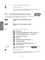
Service-Specific Call Forwarding through the Office Exchange .
Call Answering Machine . . . . . . . . . . . . . . . . . . . . .
Door Intercom . . . . . . . . . . . . . . . . . . . . . . . . . .
Terminal Portability . . . . . . . . . . . . . . . . . . . . . . . .
Multiservice Port . . . . . . . . . . . . . . . . . . . . . . . . .
Messaging Inputs . . . . . . . . . . . . . . . . . . . . . . . .
Connection Charges . . . . . . . . . . . . . . . . . . . . . . .
Accessing Special Services via the Keypad . . . . . . . . . . .
.
.
.
.
5
6
7
8
10
11
15
19
25
25
29
31
32
33
33
35
37
40
42
43
43
45
46
47
48
51
Setup . . . . . . . . . . . . . . . . . . . . . . . . . . . . . . . . . . . .
26
27
28
29
30
31
32
33
34
35
36
37
38
39
40
41
42
43
44
45
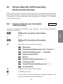
Basic Setup . . . . . . . . . . . . . . . . . . . . . . . . . . .
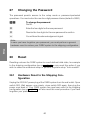
Changing the Password . . . . . . . . . . . . . . . . . . . .
Reset . . . . . . . . . . . . . . . . . . . . . . . . . . . . . .
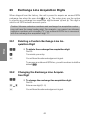
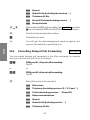
Exchange Line Acquisition Digits . . . . . . . . . . . . . . .
Changing Inhouse Extension Numbers . . . . . . . . . . . .
ISDN-Specific Settings -Point-to-Multi-point Access . . . . .
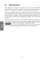
MSN Signaling . . . . . . . . . . . . . . . . . . . . . . . . .
Setup for Point-to-Point Access . . . . . . . . . . . . . . . .
Line Access Authorization . . . . . . . . . . . . . . . . . . .
Managing Call Distribution . . . . . . . . . . . . . . . . . . .
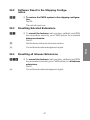
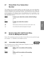
Show/Hide Calling Party Number . . . . . . . . . . . . . . .
Show/Hide Your Subscriber Number . . . . . . . . . . . . .
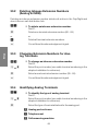
Service-Specific Call Forwarding -Point-to-Multipoint Access
Service-Specific Call Forwarding -Point-to-Point Access . . .
Door Intercom Authorization . . . . . . . . . . . . . . . . . .
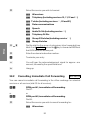
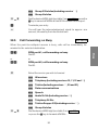
Central Abbreviated Dialing . . . . . . . . . . . . . . . . . .
Music on Hold . . . . . . . . . . . . . . . . . . . . . . . . .
Entering Date and Time . . . . . . . . . . . . . . . . . . . .
Call Statistics, Connection Charges . . . . . . . . . . . . . .
PC-Based Setup . . . . . . . . . . . . . . . . . . . . . . . .
.
.
.
.
.
.
.
.
.
.
.
.
.
.
.
.
.
.
.
.
53
57
60
60
62
63
67
74
78
81
82
90
91
91
97
103
108
109
110
111
116
Installation . . . . . . . . . . . . . . . . . . . . . . . . . . . . . . . . . 119
46
47
48
Installing Your PABX System . . . . . . . . . . . . . . . . . . 123
Signaling Connection Charges . . . . . . . . . . . . . . . . . . 143
Add-On Subassemblies . . . . . . . . . . . . . . . . . . . . . 144
Getting Started . . . . . . . . . . . . . . . . . . . . . . . . . . . . . . . 151
49
50
51
Getting Started - User Notes . . . . . . . . . . . . . . . . . . . 155
Glossary of ISDN Terms . . . . . . . . . . . . . . . . . . . . . 159
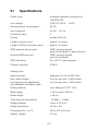
Specifications . . . . . . . . . . . . . . . . . . . . . . . . . . 161
Description
elmeg C68 - elmeg C88
1
2
Description
1
2
3
4
5
6
. . . . . . . . . . . . . . . . . . . . . . . . . . . . . . . 1
General Notes . . . . . . . . . . . . . . . . . .
PABX System Description . . . . . . . . . . . .
How to Get Your PABX System Up and Running
PABX System Shipping Configuration . . . . .
LED Indicators on Your PABX system . . . . . .
Symbols, Earpiece Signals and Ringer signals .
3
.
.
.
.
.
.
.
.
.
.
.
.
.
.
.
.
.
.
.
.
.
.
.
.
.
.
.
.
.
.
.
.
.
.
.
.
.
.
.
.
5
6
7
8
10
11
Description
Description
4
Description
General Notes
1.1
General Information for elmeg C66 elmeg C88 Users
The PABX system has been designed for normal conditions of use.
Tampering with the safety covers of your PABX system and repair through
unauthorized personnel can cause serious risks for the user.
Install and store PABX system in a dry place. Any fluids entering the enclosure
can cause electric shock or destroy the electronic circuitry inside.
Do not connect or disconnect any leads, cables or connection cords during
thunderstorms or other atmospheric discharges.
Route any leads, cables or connection cords so as to avoid the risk of persons
stumbling over them.
Use a slightly moist cloth to clean your PABX system , or use anti-static tissue.
Do not use thinner, other solvents or dry tissue to clean.
Do not connect any terminals to your PABX system other than those supplying
SELV voltage (Safety Equipment Low Voltage) and/or meeting the requirements
of ETS 300047. In the majority of cases, this requirement can be fulfilled by
using only type-approved terminal equipment.
1.2
Power Outages
A general outage of utility power (230V AC line voltage) disrupts operation of
your PABX system, leaving you unable to make or receive calls. When operating
your system at a point-to-multipoint access, you can install the type NSP
backup power subassembly to protect ISDN terminals capable of running on
exchange office battery power.
When line power returns, all extension-specific features which have been
selected by users throughout your facility, for example inbound and outbound
connections, automatic redialing, call waiting disable or internal call rerouting
will be lost. However, any features configured using the setup program will
remain unaffected by a power outage.
CAUTION!
Unplug the 230 VAC power cord before removing the
safety cover from the cable terminal bay and
proceeding to connect cables.
Replace the cable terminal cover before restoring 230 V
AC power to the unit.
5
Description
1
Description
2
PABX System Description
Your new product product is a state-of-the-art ISDN PABX system (Private
Automatic Branch Exchange) designed to operate on a DSS1 European
standard ISDN network. Your PABX system has four 4 S0 interface ports. One
port is used as a dedicated attachment interface to the ISDN network, two
ports are used to connect inhouse ISDN equipment to the unit, and the
remaining ISDN port can be optionally used for inhouse equipment or as an
external ISDN network access interface. The dedicated ISDN network access
port can be configured for the point-to-multipoint or point-to-point ISDN access
modes. You may connect a maximum of eight analog terminals. Further options
include a door intercom and external music on hold. You may allocate any
number (or direct dial-in suffix with a point-to-point access) between 00...99 to
your inhouse extensions. Your analog terminal equipment needs to support
tone dialing and the Flash key feature in order to function properly. Analog
terminals having only pulse dialing capability are restricted to features that do
not use the Flash key. Please note that not all commercially available ISDN
terminals support keypad access to the features offered by your PABX system.
Any terminal equipment attached to the unit needs to be approved by your
national standardization bodies or your network operator, if so required.
2.1
Regulatory Information
In most cases, you may directly proceed to connect your PABX system to a
single network termination unit provided by your network operator without
having to apply for a permit or consult with any specialists. However, if you wish
to connect your PABX system to two ISDN network terminations, you may have
to order that particular access configuration from your network operator, who
will in most cases have the installation work done by a specialized subcontractor.
2.2
Cleaning
You can clean your PABX system easily when you take the following precautions:
Wipe your PABX system with a slightly moist cloth, or use anti-static tissue. Do
not use thinner, other solvents or dry tissue to clean. Dry tissue may carry
electrostatic charges that can cause defects in electronic circuits. Avoid the
ingress of moisture and subsequent damage to your PABX system.
6
How to Get Your PABX System
Up and Running
Unpacking
• Unpack the PABX system and accessories from the shipping
carton and check the contents against the packing list
printed in the Installation section of this manual.
Description
Installation
• First of all, please read the PABX system description.
• Please read the installation instructions.
• Determine the location where you want to install your PABX
system.
• Install the PABX system.
• Install the desired number of ISDN wall jacks for your inhouse
ISDN bus.
• Install the desired number of wall jacks for your analog terminals.
• Connect your ISDN and analog terminals and make sure you
have their instruction manuals handy.
Getting
Started
• Connect the battery.
• Prepare the unit for operation on a
point-to-multipoint access (see Getting Started on Page 155 )
or
point-to-point access (see Getting Started on Page 157 ).
Setup
• Set up your PABX system as required (see Setup on Page
57).
Operation
• Check your setup for the proper choice of features using the
Operation section (see Page 19 ) as a reference.
You have now completed the installation, setup and checkout of your PABX
system. Enjoy staying connected with your new PABX system.
7
Description
3
Description
4
PABX System Shipping
Configuration
• The battery is disconnected.
• The password is set to 0000.
• The ISDN network access mode is set to ”DSS1 point-tomultipoint”.
• An ISDN exchange line can be acquired with the 0 or *0
key.
• The MSN entry is void.
• Incoming calls make the terminals on the active call distribution list ring, depending on the calling service.
• The”Day” call distribution list is activated.
• Terminals are not authorized to select a call distribution list.
• The following numbers are entered in the call distribution lists.
”Day” call distribution list:
10 = Telephony
11 = Data
12 = Group 3 telefax
13 = Group 4 telefax
”Night” call distribution list:
14 = Telephony
15 = Data
16 = Group 3 telefax
17 = Group 4 telefax
• Inhouse extension numbers:
First inhouse ISDN bus (S0-Tln 1):
10...19.
Second inhouse ISDN bus (S0-Tln 2):
20...29.
Third inhouse ISDN bus (S0-Tln 3):
30...39.
8
•
•
•
•
•
•
•
•
•
The analog ports are preset to tone dialing with the Flash key.
The attached terminals can access an international line.
The caller number is displayed to the called party.
The Don’t Disturb feature is not activated.
The door intercom is not activated.
The door intercom call distribution list is void.
Terminals can accept calls from the door intercom.
The abbreviated dialing list is void.
Music on hold: Callers will hear the first built-in music on hold
tune.
• The software revision at shipping time is stored instead of the
current time.
• The charge counters are set to 0.
• The charge meter printout is disabled.
• The unit stores up to 200 charge data records for the attached terminals.
• The analog charge unit counter is enabled for the analog
ports a/b1 and a/b2.
9
Description
Analog ports (a/b1...a/b8):
40...47.
Description
5
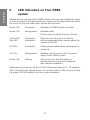
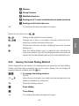
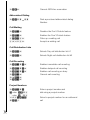
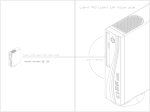
LED Indicators on Your PABX
system
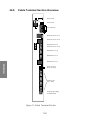
Attached to the rear side of the PABX system enclosure (see Installation, Figure
2) there are three LED status indicators. Located on the right-hand side below
the cover lid, they are visible from outside the enclosure.
Green LED
illuminated:
Indicates full PABX system operation.
Green LED
extinguished:
Hardware fault
(Yellow and red identify the type of fault).
Yellow LED
Red LED
illuminated:
illuminated:
When an error forces you to call the
field serviceplease inform service about the
status of this LED.
All LEDs
illuminated:
Startup phase (Initialization) subsequent to
powerup.
All LEDs
extinguished:
Hardware reset or loss of AC line power
supply to the PABX system .
Green LED
flashing:
Informs the user that the battery is
disconnected or needs to be replaced
(see chapter Installation).
Subsequent to powerup, the three LEDs will be illuminated for 6...10 seconds.
After completing the startup phase, the red and yellow LEDs will turn off and
the green LED will indicate error-free system operation.
10
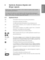
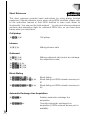
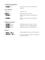
Symbols, Earpiece Signals and
Ringer signals
Please note: Terminals may differ in their earpiece signals, ringer signals
and operating procedures.
You may not be able to use all features with the specified sequence of
keys. Please refer to the instruction manuals supplied with your ISDN terminals for more detail on handling particular features.
6.1
Symbols Used
b
g
This symbol instructs you to pick up the handset.
a
This symbol instructs you to replace the handset to your
telephone set.
l
This symbol indicates an audible signal from a terminal.
Example: Your telephone set is ringing.
t
This symbol instructs you to dial a number.
1x0,
*,#
Either symbol instructs you to dial a particular numeric key or
other function key.
=x),
~,
The setup enables you to change the inhouse extension
numbers and ISDN exchange line access digits. This symbol
instructs you to dial any numeric key or other key that is not
used by a dedicated PABX system function.
R
This symbol instructs you to press the Flash key.
In-call dialing on analog terminals with tone dialing capability
requires that you press the Flash key before dialing a specific
sequence of keys, for example in order to initiate a ”broker’s
call”.
q
This symbol indicates that an acknowledgement signal is
sounding from the handset.
d
This symbol indicates a conference call.
ISDN
This symbol indicates call status.
You have picked up the handset of your telephone set.
This symbol indicates a feature that can only be accessed by
ISDN terminals.
11
Description
6
Description
This symbol indicates a feature that can only be accessed by
analog terminals.
a/b
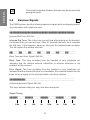
6.2
Earpiece Signals
a/b
The PABX system uses the following earpiece signals while exchanging signalling information with telephone sets.
//////////////////////////////////////////
Inhouse Dial Tone (440 Hz)
Inhouse Dial Tone. This is the tone you will hear after picking up the handset.
It indicates that you can dial now. After 20 seconds the busy tone overrides
the dial tone. If this happens, hang up, then pick the handset back up again.
This will restore the internal dial tone.
//____//____//____//____//____//____//____
Busy Tone and Error Signal (440 Hz)
Busy Tone. This tone sounding from the handset of your telephone set
indicates that the desired external subscriber or inhouse extension is not
available at the moment.
Error Signal. This tone sounding from the handset of your telephone set
indicates that the desired function is not available, the selected feature has not
been set up properly or the selected feature has been deleted.
//////////________________________________
Acknowledgement Signal (440 Hz)
This tone indicates that your entry has been accepted.
Signal Timing
/////_____/////_____/////_____/////_____///
0,5s
1s
1,5s
2s
2,5s
12
3s
3,5s
4s
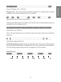
Inhouse Ringing Tone (440 Hz)
Ringing Tone. This tone indicates that the telephone is ringing at the inhouse
extension or external subscriber you are calling.
//___//___//________//___//___//________//_
Special Dial Tone (440 Hz and 500 Hz)
This tone indicates that, for example, the internal call rerouting feature has been
activated for your telephone set.
///////////////////////////////////////////
Office Dial Tone (425 Hz)
This is the permanent tone you will hear when you have claimed an outbound
ISDN line.
/__/_______________________________/__/____
Call Waiting Signal (440 Hz)
Call Waiting Signal (analog two-wire terminals only). This tone indicates that a
second external subscriber is calling while you are in a telephone conversation.
The call waiting signal will persist for a maximum of 30 seconds.
Signal Timing
/////_____/////_____/////_____/////_____///
0,5s
1s
1,5s
2s
2,5s
13
3s
3,5s
4s
Description
//////////______________________________///
Description
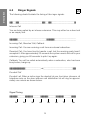
6.3
Ringer Signals
a/b
The following charts illustrate the timing of the ringer signals.
//__//_______________//__//_______________/
Inhouse Call
You are being called by an inhouse extension. This may either be a direct call
or an enquiry call.
/////___________________/////______________
Incoming Call, Reverted Call, Callback
Incoming Call: You are receiving a call from an external subscriber.
Reverted Call: You have tried to transfer a call, but the receiving party hasn’t
accepted it. After approximately 30 seconds the system reverts the call to your
extension, giving you 60 seconds to pick it up again.
Callback: You will be called automatically when a subscriber, who has been
busy before, hangs up.
//////////__________ >8s___________________//
Doorbell Call
Doorbell call. When a visitor rings the doorbell at your front-door intercom, all
telephone sets on the door intercom call distribution list will ring for approximately one minute as shown below.
Signal Timing
/////_____/////_____/////_____/////_____///
1s
2s
3s
4s
5s
14
6s
7s
8s
Operation
Operation
elmeg C68 - elmeg C88
15
16
Operation
8
9
10
11
12
13
14
15
16
17
18
19
20
21
22
23
24
25
26
Inhouse & Inbound/Outbound Connections .
Team Call . . . . . . . . . . . . . . . . . .
Transferring Calls . . . . . . . . . . . . . .
Automatic Callback . . . . . . . . . . . . .
Reserving an ISDN Exchange Line . . . . . .
Three-Party Conference . . . . . . . . . . .
Central Abbreviated Dialing . . . . . . . . .
Call Waiting . . . . . . . . . . . . . . . . .
Managing Call Distribution . . . . . . . . . .
Call Rerouting . . . . . . . . . . . . . . . .
Project Numbers . . . . . . . . . . . . . .
Service-Specific Call Forwarding through the
Office Exchange . . . . . . . . . . . . . . .
Call Answering Machine . . . . . . . . . . .
Door Intercom . . . . . . . . . . . . . . . .
Terminal Portability . . . . . . . . . . . . . .
Multiservice Port . . . . . . . . . . . . . . .
Messaging Inputs . . . . . . . . . . . . . .
Connection Charges . . . . . . . . . . . . .
Accessing Special Services via the Keypad .
17
.
.
.
.
.
.
.
.
.
.
.
.
.
.
.
.
.
.
.
.
.
.
.
.
.
.
.
.
.
.
.
.
.
.
.
.
.
.
.
.
.
.
.
.
.
.
.
.
.
.
.
.
.
.
.
.
.
.
.
.
.
.
.
.
.
.
.
.
.
.
.
.
.
.
.
.
.
.
.
.
.
.
.
.
.
.
.
.
19
25
25
29
31
32
33
33
35
37
40
.
.
.
.
.
.
.
.
.
.
.
.
.
.
.
.
.
.
.
.
.
.
.
.
.
.
.
.
.
.
.
.
.
.
.
.
.
.
.
.
.
.
.
.
.
.
.
.
.
.
.
.
.
.
.
.
.
.
.
.
.
.
.
.
42
43
43
45
46
47
48
51
Operation
Operation . . . . . . . . . . . . . . . . . . . . . . . . . . . . . . . 15
18
Operation
7
Inhouse & Inbound/Outbound
Connections
a/b-ISDN
7.1
Accepting Calls
a/b-ISDN
l
b
g
a
Your telephone is ringing.
7.2
Call Pickup (incoming calls only)
Pick up the handset.
Have your conversation with the caller.
Hang up.
a/b-ISDN
On a nearby desk, an incoming call makes a telephone set attached to your
PABX system ring. You wish to accept this call on your telephone set.
b
*4
g
7.3
Pick up the handset. You will hear the inhouse dial tone.
Dial *4.
You are now connected with the caller.
Inhouse Connections
a/b-ISDN
Any telephone call, telefax or data transmission between on-premise analog
and ISDN terminals is an inhouse connection. Contrarily, any connection
between an analog terminal and an ISDN terminal attached to the point-to-multipoint ISDN access is an outbound call you will be charged for by your network
operator.
19
Operation
The examples given in the following operating instructions refer to a simple
telephone connection, that is a call established between any two subscribers
or inhouse extensions. Also, the instructions relating to analog telephone sets
cover only the functionality offered by telephone sets or other terminals with
tone dialing capability and a fully functional Flash key.
7.4
Making Inhouse Calls
a/b-ISDN
You wish to establish an inhouse connection with an extension attached to
your PABX system.
Operation
b
t
Pick up the handset. You will hear the inhouse dial tone.
Dial up the desired inhouse extension. You will hear the ringing
tone from the earpiece, indicating that the desired inhouse
extension is being called.
The desired inhouse party picks up the handset.
g
a
7.5
Have your conversation with the desired party.
Replace the handset to terminate the inhouse call or let the
other party hang up. You will hear the busy tone. Replace the
handset. This will terminate your inhouse connection.
Outbound Connections
a/b-ISDN
Your PABX system features one or two external ISDN access ports. You can
use the two B-channels offered by an ISDN access to run two external
connections at a time, even with two different parties. You can, for example,
call an external client while transferring data to another client at the same time.
With a point-to-point ISDN access, any incoming call to the PABX system that
contains an ”0" as the direct dial-in suffix or a non-existing direct dial-in number,
will make all the telephone sets on the current call distribution list ring and the
master bell (if the unit is equipped with the door intercom subassembly) ring.
When you initiate an outbound call with your PABX system, the unit automatically sends the service identifier programmed for the calling analog extension
or stored in the ISDN terminal to the receiving subscriber.
Please note: ISDN terminals attached directly to a point-to-multipoint access
and the inhouse ISDN bus may exhibit different earpiece signals, ringer signals
and require other operating procedures than analog terminals connected to
the PABX system. This is not due to technical shortcomings of the PABX system
but rather dependent on the ISDN products in use.
20
7.6
Making Outbound Calls
a/b-ISDN
You wish to establish a connection with an external subscriber or an inhouse
extension attached to your point-to-multipoint access.
Pick up the handset. You will hear the inhouse dial tone.
If you wish to make a call via any available ISDN exchange
line,dial = or *0.
To acquire an exchange line via a particular ISDN network
access port, dial the following:
*81
To initiate an outbound call via ISDN network access port #1,
dial *81.
*82
To initiate an outbound call via ISDN network access port #2,
dial *82.
You will hear the office dial tone.
If you hear the busy tone after dialing 0, 81 or 82, your
telephone set is not authorized or the ISDN exchange line is
busy.
t
Dial the desired subscriber number.
You will hear the ringing tone from the earpiece, indicating that
the external subscriber is being called. The called subscriber
picks up the handset.
g
a
Make your call.
Hang up.
21
Operation
b
=or*0
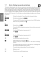
7.7
Block Dialing (preparatory dialing)
a/b
Operation
The block dialing feature lets the user compose a complete subscriber number
at his or her terminal, send it to the PABX system for intermediate storage and
initiate the dialing procedure afterwards. Some networks may demand that you
use block dialing in order to get through to the remote terminal you wish to call.
For more detail on block dialing, please refer to the instructions manual supplied
with your ISDN terminal. You can also use block dialing to address an inhouse
extension.
b
*55
0
Pick up the handset. You will hear the inhouse dial tone.
Dial the block dialing digit *55.
To use any ISDN network access port of your PABX system
that is currently available, dial 0.
or
*0
Alternatively, dial *0.
To use the ISDN network access port of your choice, proceed
as follows:
*81
To call via ISDN network access port #1:
Dial *81.
or
*82
To call via ISDN network access port #2:
Dial *82.
t
#
Dial the desired subscriber number.
Initiate dialing by pressing the # key.
This will send your dialing request to the office exchange
system.
You will hear the ringing tone from the earpiece, indicating that
the external subscriber is being called.
The called subscriber picks up his or her handset.
g
a
Make your call.
Terminate your call by hanging up.
22
7.8
Line Access Management
a/b-ISDN
7.9
Automatic ISDN Line Acquisition
a/b-ISDN
The PABX system supports a special procedure that allows individual extensions to acquire an outgoing ISDN line either automatically or manually. With
this feature activated, you will receive immediate ISDN line access after picking
up the handset. You will hear the office dial tone, prompting you to dial an
external subscriber number. If you wish to dial an inhouse number, pick up the
handset and press the * key to switch to inhouse dialing. If you wish to make
an inhouse call but receive the busy tone after picking up the handset (all
outgoing ISDN lines busy), you should disable the automatic exchange line
acquisition feature, hang up and pick up the handset again. You will then hear
the inhouse dial tone.
7.9.1
b
*52
q
a
7.9.2
b
*
t
Enabling Automatic Exchange Line Acquisition
Pick up the handset. You will hear the inhouse dial tone.
Dial *52.
You will hear the acknowledgement signal .
Replace the handset to activate the feature.
Inhouse Dialing
Pick up the handset. You will hear the office dial tone.
Dial * to switch to inhouse dialing.
You can dial up inhouse extensions now.
23
Operation
This feature is only available if you have two outgoing ISDN lines. You can use
the PABX system setup to preselect an ISDN line to be used by a particular
terminal or set of terminals. This feature is, for example, useful if two companies
share the PABX system or if you need a dedicated line for priority calls, allowing
the connection charges to be exactly allocated to either company and their
terminal equipment. This line access preselection setting cannot be overriden
by acquiring a particular ISDN line.
Operation
7.9.3
Disabling Automatic Exchange Line Acquisition (ISDN line
not busy)
b
*#52
q
t
g
a
7.9.4
b
#52
q
t
g
a
Pick up the handset. You will hear the office dial tone.
Dial *#52 to deactivate the feature.
You will hear the acknowledgement signal .
You can dial up inhouse extensions now.
Make your inhouse call.
Hang up. The feature will remain disabled.
Disabling Automatic Exchange Line Acquisition (ISDN line
busy)
Pick up the handset. You will hear the busy tone.
Dial #52to deactivate the feature.
You will hear the acknowledgement signal .
You can dial up inhouse extensions now.
Make your inhouse call.
Hang up. The feature will remain disabled.
24
8
Team Call
a/b-ISDN
9
Transferring Calls
a/b-ISDN
9.1
Transferring Calls with Prior Notice
a/b-ISDN
You wish to transfer an inhouse call or external call to another extension,
notifying the receiving party beforehand.
• The party put on hold will hear music on hold, if selected in the
setup.
g
During a telephone conversation with an external subscriber
you wish to transfer the call to another inhouse extension.
R
Press the Signaling key. You will hear the inhouse dial tone
from the earpiece.
t
Dial up the desired inhouse extension. You will hear the ringing
tone from the earpiece, indicating that the desired extension is
being called. The called inhouse party picks up the handset.
(If you hear the busy tone, press the Signaling key R to restore
the call to your telephone.)
g
Make your inhouse call, notifying the called party of the
external subscriber waiting for him or her.
a
Hang up.
The called inhouse extension accepts the call.
If you have an analog telephone set and the called party is busy, you can restore
the call by pressing the Flash key.
25
Operation
This feature can only be used with a point-to-multipoint access. In the setup,
you can allocate up to 8 inhouse extensions to an MSN. When an inhouse party
dials this MSN, all terminals included in this setup item will ring.
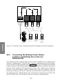
9.2
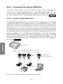
Connecting Two External Subscribers
Subsequent to an Enquiry Call
Please note that ISDN terminals use special keypad features or a dedicated
key to connect the two external subscribers involved in an enquiry call situation.
When you wish to connect the two external subscribers involved in an enquiry
call, you should be aware of the following:
Operation
• While the two external subscribers talk, two B-channels will
be occupied at your PABX system.
• Whoever has initiated the call in the first place, they will pay for
the call charges. For example, when you have called one
external party, then made an enquiry call to another external
party and finaly connected them with each other, you will pay
for two calls. Contrarily, when you have received a call and
made a subsequent enquiry call to a third party, the first caller
will pay for himself, and you will have to pay only for the enquiry call.
g
You are making an enquiry call to an external party, putting the
first party on hold.
You wish to connect both parties and withdraw from the
conversation.
R
*4
a
Press the R key.
Press *key, followed by the 4 key.
Hang up.
By hanging up, you will connect the remaining parties with each other.
26
9.3
Transferring Calls without Prior Notice
a/b-ISDN
g
R
You are making a call.
t
Dial up the desired inhouse extension. You will hear the ringing
tone from the earpiece, indicating that the desired extension is
being called.
r
(If you hear the busy tone, press the Signaling key once more
to restore the call to your telephone.)
a
Replace the handset. The desired extension is being called.
The called inhouse party picks up the handset and accepts the
call.
9.4
Press the Signaling key. You will hear the inhouse dial tone
from the earpiece.
Enquiry Call
a/b-ISDN
The enquiry call feature enables you to interrupt an inhouse or external call and
make a second call, referred to as an enquiry call. This feature puts the first
caller or called party on hold, so he or she won’t be able to listen in on your
enquiry call. After terminating your enquiry call, you can continue with your first
call. The party put on hold will hear music on hold, if selected in the setup.
g
r
During an ongoing call, you wish to make an enquiry call.
t
Dial up the desired inhouse extension. You will hear the ringing
tone from the earpiece, indicating that the inhouse extension is
being called. The called party picks up the handset.
g
Make your enquiry call.
When using an analog telephone, press the Flash key. You will
hear the inhouse dial tone from the earpiece.
To terminate the enquiry call, press the cutoff key of your ISDN
telephone set (terminal-specific).
27
Operation
You can transfer calls to a third party without prior notice (immediate transfer).
To transfer an ongoing call to another party on your premises without giving
prior notice, simply dial the desired extension number and hang up. The
extension set will ring, allowing the called party to pick up the handset and
accept the call.
Operation
or
or
R*1
When using an analog terminal, press the Flash key R
followed by *1 to terminate the second call and return to the
first party.
g
Continue with the first call.
9.5
Broker’s Call (terminal-specific)
a/b-ISDN
The broker’s call feature allows you to switch between two inhouse parties,
two external subscribers, or an inhouse party and an external subscriber and
talk to either party in turn. The external subscriber will hear music on hold, if
selected in the setup.
g
R
During an ongoing call you wish to make an enquiry call.
t
Dial up the desired party. You will hear ringing tone from the
earpiece, indicating that the party is being called. The called
party picks up the handset.
g
R*2
Make your enquiry call.
g
Continue with your first call.
or
or
r
When using an ISDN telephone set press the Signaling key to
switch between the two parties.
g
a
Continue with your call.
When using an analog telephone set, press the Flash key.
When using an ISDN telephone set, press the Signaling key.
You will hear the inhouse dial tone from the earpiece, while the
first is being put on hold.
When using an analog telephone set press the Flash key,
followed by *2, to switch between the two parties.
Hang up. Please note that when you terminate a broker’s call
with one inhouse party and one external party, you will connect
the two remaining parties by hanging up! If you hang up on two
external subscribers, the current connection will be
terminated and the connection put on hold will reoccur as a
”reverted call”.
28
10
Automatic Callback
10.1
Automatic Callback on Busy
a/b-ISDN
You dial up an inhouse extension that is busy. You will hear the busy tone. Dial
*4 and hang up. As soon as the party replaces the handset to his or her
telephone, your telephone set will ring.
This function is only available with telephone sets that support in-call tone
dialing!
b
t
Pick up the handset. You will hear the inhouse dial tone.
*4
q
Dial *4.
a
Replace the handset.
Dial up the desired inhouse extension. You will hear the busy
tone from the earpiece.
You will hear the acknowledgement signal, followed by the
busy tone.
When the busy party hangs up, your telephone set will ring.
l
b
Your telephone is ringing.
When you pick up the handset, the extension you have
requested a callback for will be called. If he or she picks up the
phone, you can finally make your call.
29
Operation
Each inhouse party can choose to make one automatic callback or ISDN
exchange line reservation request. The feature requested last (callback or ISDN
line reservation) overrides all previous requests. Access to this feature requires
an ISDN terminal with in-call keypad dialing capability. Please note that
automatic callback is only supported for the first MSN stored in any ISDN
terminal. This feature will be automatically cancelled at 0:00 hours.
10.2
Automatic Callback on No Answer
a/b-ISDN
You dial up an inhouse extension. The called party doesn ‘t respond and you
hear nothing but the ringing tone. Dial *4 and hang up. If the person returns to
his or her desk and makes a call, your telephone set will ring after he or she
has hung up.
Operation
This function is only available with telephone sets that support in-call tone
dialing!
b
t
Pick up the handset. You will hear the inhouse dial tone.
*4
Dial *4. You will hear the acknowledgement signal, followed
by the busy tone.
a
Replace the handset.
Dial the desired extension number. You will hear the ringing
tone from the earpiece.
As soon as the called party hangs up for the first time after
returning to his or her desk, your telephone set will ring.
l
b
10.3
b
#4
Your telephone is ringing.
When you pick up the handset, the extension you have
requested a callback for will be called. If he or she picks up the
phone, you can finally make your call.
Cancelling an Automatic Callback Request
a/b-ISDN
Pick up the handset. You will hear the inhouse dial tone.
Dial #4.
Wait for the the acknowledgement signal, followed by the
inhouse dial tone.
a
Hang up. The feature has been cancelled now.
30
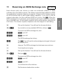
Reserving an ISDN Exchange Line a/b-ISDN
Each inhouse party can choose to make one automatic callback or ISDN
exchange line reservation request. The feature requested last (callback or ISDN
line reservation) overrides al previous requests. Access to this feature requires
an ISDN terminal with in-call keypad dialing capability. If you wish to call an
external subscriber, but the outbound ISDN line is busy, dial *4. When the
ISDN exchange line is released, your telephone will ring to inform you that the
line is available now. All reservation requests will be automatically cancelled at
0:00 hours. This feature requires telephone sets that support in-call dialing.
b
=or*0
Pick up the handset. You will hear the inhouse dial tone.
If you wish to use any available ISDN line, dial = or *0.
To reserve an ISDN exchange line, dial:
*81
*82
*81= port #1.
*82= port #2.
The ISDN exchange line is busy.
*4
Dial *4. You will hear the acknowledgement signal, followed
by the busy tone.
a
l
b
=or*0
Hang up. The ISDN exchange line has been reserved now.
Your telephone is ringing.
Pick up the handset. You will hear the inhouse dial tone.
Dial = or *0.
To reserve an ISDN exchange line, dial:
*81
*82
*81= port #1
*82= port #2.
You will hear the office dial tone.
t
Dial the desired subscriber number.
31
Operation
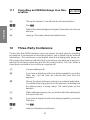
11
Operation
11.1
Cancelling an ISDN Exchange Line Reservation
a/b-ISDN
b
#4
q
Pick up the handset. You will hear the inhouse dial tone.
a
Hang up. The feature has been disabled now.
12
Dial #4.
Wait for the acknowledgement signal, followed by the inhouse
dial tone.
Three-Party Conference
a/b
Please note that ISDN telephone sets may require terminal-specific operating
procedures. A conference involves three parties, two of which may be external
subscribers. The conference is terminated when the initiating party hangs up.
Either party who has been admitted to the conference can hang up at any time,
leaving the initiating subscriber and the third party behind. You can initiate a
three-party conference from within an ongoing call.
g
r
You are making a call.
t
Dial up the desired inhouse extension or external subscriber.
You will hear the ringing tone from the earpiece, indicating that
the desired party is being called. The called picks up the
handset.
g
While making an enquiry call, you wish to admit the called party
to the previous call.
r
If you have a telephone with tone dialing capability, press the
Flash key.
*3
d
Dial *3.
If you have a telephone with tone dialing capability, press the
Flash key. You will hear the inhouse dial tone from the
earpiece.
Hold your telephone conference.
32
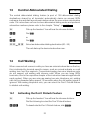
13
Central Abbreviated Dialing
a/b-ISDN
b
*#
Pick up the handset. You will hear the inhouse dial tone.
or
or
#*
==x))
Dial #*.
Operation
The central abbreviated dialing feature (a pool of 100 abbreviated dialing
destinations shared by all terminals) automatically claims an unused ISDN
exchange line and dials a prestored number when the user enters a destination
code. For instructions on how to store abbreviated dialing codes and pertinent
subscriber numbers please refer to the chapter ”Setup”, page 57.
Dial *#.
Select an abbreviated dialing destination (00...99)
The unit dials up the desired subscriber now.
14
Call Waiting
a/b-ISDN
When a second call comes in while you have an external subscriber on the line,
this is indicated by terminal-specific means, such as a visual indicator or a call
waiting tone from the earpiece. Conventional analog two-wire telephone sets
do not support call waiting with inhouse calls! When you are using ISDN
terminals, refer to the respective chapter of the instruction manual supplied with
each product. When you are using an analog two-wire telephone set, waiting
calls will be discarded after approx. 30 seconds when the call waiting signal is
ignored. With analog telephone sets, you can select the Don’t Disturb feature
to disable call waiting.
14.1
b
Activating the Don’t Disturb Feature
Pick up the handset. You will hear the inhouse dial tone.
Dial the following to select the Don’t Disturb feature:
*51
To deactivate the Don’t Disturb feature, dial:*51.
33
a/b
Operation
or
or
#51
q
To activate the Don’t Disturb feature, dial: #51.
a
Hang up.
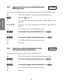
14.2
You will hear the acknowledgement signal for approx. 1
second, followed by the inhouse dial tone.
Picking Up a Waiting Call (enquiry call)
a/b
If you wish to talk to the waiting subscriber, dial *4. You will be connected
with the waiting caller, while the first party is put on hold.
g
During an ongoing a call you hear the call waiting signal from
the earpiece. You wish to welcome the waiting caller.
r
If you have a telephone with tone dialing capability, press the
Flash key.
*4
g
Dial *4.
14.3
You are now connected with the waiting subscriber, while the
first caller is being put on hold (see ”Enquiry Call” for reference).
For additional instructions, please refer to the sections
”Broker’s Call” or ”Three-Party Conference”.
Accepting a Waiting Call
a/b
g
During an ongoing call, you hear the call waiting signal from the
earpiece.
a
l
b
Hang up (terminating the first call).
Your telephone is ringing.
Pick up the handset. You are now connected with the waiting
subscriber.
34
Managing Call Distribution
a/b-ISDN
The PABX system manages two internal call distribution lists, referred to as Day
and Night. Please note that the naming Day/Night is traditional usage in the
field of PABX engineering and does not necessarily refer to a particular time of
day. The names Day and Night are only used to point out that the system
supports two different call distribution configurations. Call distribution lists are
service-sensitive, that is, any terminal on a list will only ring if its service setting
matches the service identifier sent with the incoming call. If an external
subscriber number is on a call distribution list, the charge units incurred by
redirecting a call to that number are charged to the account of an inhouse
extension. Allocating terminals or external subscriber numbers to the Day or
Night call distribution lists is done in the setup. A call distribution list supports
up to six terminals or external subscriber numbers. The Day or Night call
distribution lists can only be toggled but never be used at the same time.
Terminals that have not exchange line authorization can be included in a call
distribution list but will not ring.
The call distribution lists can either be selected by an authorized user in
possession of the password or by an authorized extension.
You can switch between the two call distribution lists to direct an incoming call
to the terminals of your choice.
15.1
Call Distribution List - Point-to-Multipoint
a/b-ISDN
A call distribution list contains the telephone sets you wish to ring when an
incoming call is received. In order for incoming calls to make all terminals on a
call distribution list ring, an MSN must be allocated to that call distribution list.
Notwithstanding, each terminal may have an MSN allocation of its own.
15.2
Call Distribution List - Point-to-Point
a/b-ISDN
A call distribution list contains the telephone sets you wish to ring when an
incoming call is received. Calls are distributed using the call distribution list if
an external subscriber dials a direct dial-in suffix that doesn’t address any
inhouse extension, for example ”0" (factory setting).
35
Operation
15
15.3
Password-Protected Call Distribution
Management
a/b-ISDN
Operation
Any person in possession of the password may select a call distribution list.
b
**
q
Pick up the handset. You will hear the inhouse dial tone.
====
Enter the four-digit password, for example 0000 (factory
setting).
q
401
You will hear the acknowledgement signal.
or
or
402
q
a
To select the Night call distribution list , dial 402.
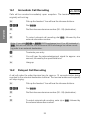
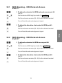
15.4
Press the * key twice.
You will hear the acknowledgement signal (approx. one
second).
To select the Day call distribution list , dial 401.
You will hear the acknowledgement signal.
Hang up.
Selection of Call Distribution Lists
through Authorized Parties
a/b-ISDN
Any authorized extension may select a distribution list.
b
*64
Pick up the handset. You will hear the inhouse dial tone.
or
or
#64
q
a
To select the Night call distribution list, dial #64.
To select the Day call distribution list, dial *64
You will hear the acknowledgement signal.
Hang up.
36
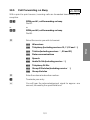
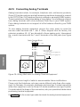
16
Call Rerouting
a/b-ISDN
It gives you the option of rerouting calls from an external party to an external
terminal of your choice (occupying both B-channels), from an inhouse terminal
to an external terminal, or from an inhouse terminal to another inhouse terminal.
Calls rerouted to an external destination will be charged to the owner of the
PABX system, while the initial incoming call will be charged to the caller himself.
The PABX system cannot process any further incoming call on either dual-line
ISDN access while configured to reroute incoming calls to an external destination.
There are three call rerouting options, one of which can be active at a time:
• Immediate Call Rerouting: Calls will be rerouted immediately
upon reception. The terminal addressed originally will not
ring.
• Delayed Call Rerouting: A call will make the called terminal
ring for approx. 15 seconds before being rerouted to the selected destination terminal. The terminal addressed originally
will stop ringing.
• Call Rerouting on Busy: If the desired party is busy, the call
will be rerouted to the selected destination terminal.
Avoid delays of more than 10 seconds between digits. You should preferably
terminate your entry with the # key. The acknowledgement signal indicates
that your entry has been accepted and stored. If you don’t press the # key
you will hear the acknowledgement signal approx. 10 seconds after entering
the last digit, provided your entries were correct. This signal indicates that your
entries have been stored. If you hang up before hearing the acknowledgement
signal, the procedure will be cancelled without storing.
Note: Some ISDN telephone sets have a dedicated function key for the call
rerouting feature.
37
Operation
Call rerouting is a standard feature built into your PABX system. You won’t have
to order that service feature from your network operator.
16.1
Immediate Call Rerouting
a/b-ISDN
Operation
Calls will be rerouted immediately upon reception. The terminal addressed
originally will not ring.
b
*61
t
Pick up the handset. You will hear the inhouse dial tone.
Dial *61.
Dial the inhouse extension number (00...99) (destination).
or
t
To select external call rerouting dial *0, followed by the
external subscriber number.
Note: If you dial *81 or *82 (ISDN exchange line #1 or #2) instead of
*0, the unit will use the first or second ISDN exchange line when rerouting calls to an external destination.
#
q
Terminate your entry.
a
Hang up.
16.2
You will hear the acknowledgement signal for approx. one
second, followed by the special dial tone.
Delayed Call Rerouting
a/b-ISDN
A call will make the called terminal ring for approx. 15 seconds before being
rerouted to the selected destination terminal. The terminal addressed originally
will stop ringing.
b
*62
t
Pick up the handset. You will hear the inhouse dial tone.
Dial *62.
Dial the inhouse extension number (00...99) (destination).
or
t
To select external call rerouting, enter = or *0, followed by
the external subscriber number.
38
Note: If you dial *81 or *82 (ISDN exchange line #1 or #2) instead of
*0, the unit will use the first or second ISDN exchange line when rerouting calls to an external destination.
#
q
Terminate your entry.
a
Hang up.
Call Rerouting On Busy
a/b-ISDN
If the desired party is busy, the call will be rerouted to the subscriber selected
as the destination.
b
*63
t
Pick up the handset. You will hear the inhouse dial tone.
Dial *63.
Dial the inhouse extension number (00...99) (destination).
or
t
To select external call rerouting, enter *0, followed by the
subscriber number.
Note: If you dial *81 or *82 (ISDN exchange line #1 or #2) instead of *0,
the unit will use the first or second ISDN exchange line when rerouting calls to
an external destination.
#
q
Terminate your entry.
a
Hang up.
You will hear the acknowledgement signal for approx. one
second, followed by the special dial tone.
39
Operation
16.3
You will hear the acknowledgement signal for approx. one
second, followed by the special dial tone.
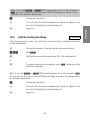
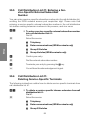
16.4
Cancelling Call Rerouting
a/b-ISDN
Call rerouting activity is indicated by the special dial tone. Call rerouting
(immediate, delayed, on busy) can be cancelled on the initiating terminal using
a special procedure.
Operation
b
#61
Pick up the handset. You will hear the special dial tone.
To cancel call rerouting (immediate, delayed, on busy):
Dial #61, #62 or #63.
#62
or
#63
q
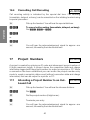
17
You will hear the acknowledgement signal for approx. one
second, followed by the inhouse dial tone.
Project Numbers
a/b-ISDN
A project is created by entering an ID code and subsequent project number of
6 digits maximum length. A project stores the connection data and charge
information tagged with the project number for output on a printer or PC. When
a connection has been established you can invoke the project number entry
mode to create a complete data record (without connection data and charge
information) that can be output to a printer or PC.
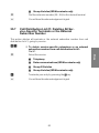
17.1
b
*50
t
#
q
Allocating a Project Number to an Outbound Call
a/b-ISDN
Pick up the handset. You will hear the inhouse dial tone.
Dial *50.
Dial the project number (6 digits max.).
Terminate your entry.
You will hear the acknowledgement signal for approx. one
second, followed by the inhouse dial tone.
40
=or*0
If you wish to make your call via any available ISDN line, dial =
or *0.
t
g
Dial the external subscriber number.
Make your call.
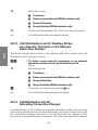
17.2
Allocating a Project Number to an Incoming Call Received by an ISDN Terminal
ISDN
You can use this feature if your ISDN terminal supports in-call dialing.
l
b
g
*50
t
#
q
Your telephone is ringing.
g
Continue with your call.
17.3
l
b
g
R
Pick up the handset.
You are making a call. You wish to charge the call to a project.
Dial *50.
Dial the project number (6 digits max.).
Terminate your entry.
You will hear the acknowledgement signal for approx. one
second.
Allocating a Project Number to an Incoming Call Received by an Analog Terminal
a/b
Your telephone is ringing.
Pick up the handset.
You are making a call. You wish to charge the call to a project.
Press the Signaling key. You will hear the inhouse dial tone
from the earpiece.
41
Operation
Note:You can also use this feature from within an external enquiry call.
Operation
*50
t
#
q
Dial *50.
R
Press the Signaling key. Your project number has been stored
now and you can get back to the calling party.
g
Continue with your call.
18
Dial the project number (6 digits max.).
Terminate your entry.
You will hear the acknowledgement signal for approx. one
second, followed by the inhouse dial tone.
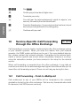
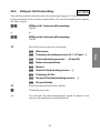
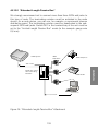
Service-Specific Call Forwarding
through the Office Exchange
a/b-ISDN
Call forwarding is a service feature implemented in the office exchange system
of your network operator. When you order this feature from your network
operator, the PABX system will allow you to use it. For more detailed information, please contact your network operator. Forwarding to the external destination is service-specific and occurs either immediatey, delayed or on busy,
using the subscriber number you have entered in the setup for the desired
service.
When call forwarding is requested from the office exchange, it may take as
much as one minute for the acknowledgement signal to be returned after you’ve
issued the call forwarding request. Please do not hang up during this time.
18.1
Call Forwarding - Point-to-Multipoint
Calls addressed to any of your MSNs will be forwarded to the selected
destination (setup) by the office exchange. Calls are only forwarded when both
B-channels of an ISDN access are busy.
42
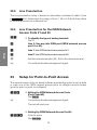
18.2
Call Forwarding - Point-to-Point
19
Call Answering Machine
19.1
Picking Up a Call from an Answering
Machine
a/b-ISDN
You can pick up a call on your telephone set while an inhouse party or external
subscriber is already leaving his or her message on the call answering machine.
Any call that is still ringing at the call answering machine (the machine hasn’t
turned on yet), can be accepted using the ”Call Pickup” *4feature.
b
*70
g
20
Pick up the handset. You will hear the inhouse dial tone.
Dial *70.
You can make the call on your telephone set.
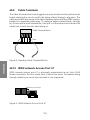
Door Intercom
a/b-ISDN
The door intercom line is interfaced via the door intercom add-on assembly.
When a visitor presses the bell pushbutton at the front door intercom, all
terminals on the door intercom call distribution list #1 or #2 will ring. The door
intercom feature can only be accessed by terminals which have the door
intercom authorization (please refer to Programming).
If an external subscriber number is listed on the door intercom call distribution
list, the doorbell call is forwarded to that external subscriber when a visitor rings
the doorbell. The charge units incurred by this forwarded call are charged to
the internal door intercom extension number.
l
b
You hear the doorbell call on your telephone set.
Pick up the handset.
43
Operation
With a point-to-point access, all incoming calls are forwarded ”by service” (see
Setup).
g
You can now welcome the visitor at the door intercom.
Operation
You wish to open the door.
r
If you have a telephone with tone dialing capability, press the
Flash key.
*9
Dial *9 to actuate the door opener for approx. three
seconds. You will hear the acknowledgement signal for one
second.
g
a
Continue with your call.
To terminate the call to the door intercom, hang up.
Note: If you hear the doorbell while using another telephone set, you can
dial the door intercom extension number and accept the doorbell call if you
are suffiently authorized.
You can also actuate the door opener on any inhouse telephone set by dialing *9, without having to call the door intercom. This feature is supported by ISDN telephone sets that do not support in-call tone dialing. Terminate the doorbell call and hang up. Pick up the handset again and dial
*9.
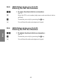
20.1
Door Intercom - Call Distribution Management through Authorized Parties
a/b-ISDN
b
*65
#65
q
Pick up the handset. You will hear the inhouse dial tone.
a
Hang up.
To select door intercom call distribution list # 1, dial *65.
To select door intercom call distribution list # 2, dial #65.
You will hear the acknowledgement signal for approx. one
second, followed by the inhouse dial tone.
44
20.2
Door Intercom - Password-Protected
Call Distribution Management
a/b-ISDN
b
**
q
Pick up the handset. You will hear the inhouse dial tone.
====
Enter the four-digit password, for example 0000 (factory
setting).
q
501
You will hear the acknowledgement signal.
or
or
502
q
To select door intercom call distribution list # 2, dial 502.
a
Hang up.
21
Press the * key twice.
You will hear the acknowledgement signal for approx. one
second.
To select door intercom call distribution list # 1, dial 501.
You will hear the acknowledgement signal for approx. one
second, followed by the inhouse dial tone.
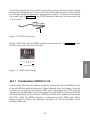
Terminal Portability
ISDN
Terminal portability is only supported on the same bus (inhouse ISDN bus port).
You wish to move during an ongoing call and resume the call elsewhere in your
building. You can activate the portability feature on your terminal, disconnect
it from the inhouse ISDN bus and carry it to the desired location. If you reconnect
your terminal to the inhouse ISDN bus and disable the terminal portability
feature within three minutes, you can resume the call. For more detail on
operating procedures, please refer to the instruction manual of your ISDN set.
45
Operation
Any inhouse party in possession of the password may select a list.
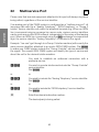
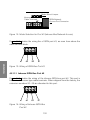
22
Multiservice Port
a/b
Operation
Please note that terminal equipment attached to this port will always ring when
being called, regardless of the service identifier.
If an analog port of the PABX system is configured as a ”multiservice port", all
incoming calls with the a ”Analog Telephony”, ”ISDN Telephony” or ”Group 3
telefax" service identifier will make the attached terminal ring. When an ISDN
line is accessed using an excange line acess code, various service identifiers
can be sent accross the ISDN network, independent of the setup of that analog
port. When an ISDN line is accessed using the *0 exchange line aqcuisition
digit, the service identifier ”Analog Telephony” is included in the signal.
Example: You can’t get through to a Group 3 telefax machine (with exactly the
same service identifier) attached to a remote ISDN PABX system. Dial *83
to make your PABX system include the ”Group 3 telefax” service identifier into
the signal. The remote ISDN PABX system will identify the type of service and
direct the call to the desired telefax machine.
You wish to establish an outbound connection with a
particular service.
*83
You wish to send a telefax and include the ”Group 3 telefax”
service identifier.
Dial * 83.
or
or
*84
You wish to include the ”Analog Telephony” service identifier.
Dial *84.
or
or
*85
You wish to include the ”ISDN telephony” service identifier.
Dial *85
t
Enter the external subscriber number.
The desired party is being called.
46
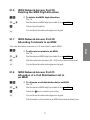
23
Messaging Inputs
Operation
To be implemented in a future release.
47
24
Connection Charges
a/b-ISDN
Operation
You can obtain call charge readouts on any ISDN terminal or two dedicated
analog terminals attached to your system.
Your PABX system provides storage capacity for a maximum of 200 connection
records. You can send this data to a printer to obtain a hardcopy printout or
save them to disk on a desktop or laptop personal computer. You can set up
your PABX system to log calls for selected terminals only, or for all terminals
attached to your system.
24.1
ISDN Terminals
You can obtain call charge readouts on any ISDN terminal that supports this
function.
24.2
Analog Terminals
This feature supports the display of connnection charges on any ISDN terminal
equipped with this feature. Additionally, your PABX system gives you the option
of displaying charges on the analog terminals attached to the analog ports a/b1
and a/b2, provided they support this feature. Please note that online call charge
metering is a special service feature that will have to be ordered separately from
your network operator. No system setup is required, the two analog ports can
be preset accordingly using the jumpers ”J1" and ”J2" (during installation).
When shipped from the factory, charge metering is enabled.
Please note that charge metering is the sole responsibility of the network
operator. Since ISDN uses special techniques to transfer call charge information, connection data may also be sent after the connection has been terminated. The large variety of commercially available analog terminals makes it
impossible to guarantuee that the data sent by your PABX system subsequent
to the termination of a connection will be received properly by your terminal.
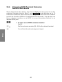
24.3
Printers and Personal Computers
If the printer, desktop or laptop PC is turned off when you output charge data
from the PABX system to the unit, or if the printer runs out of paper, the data
will not be discarded or lost. You can set up your system to resume outputting
the charge data (see Page 114 for detail).
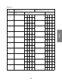
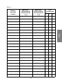
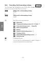
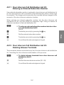
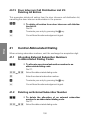
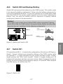
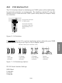
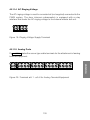
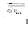
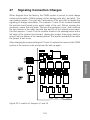
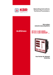
Figure 1 illustrates a data record as output on a printer attached to the system
(only the boldface text will be printed) or transferred to a desktop or laptop PC.
48
Legend for Figure 1:
G = self-initiated outbound call
G1: via ISDN line # 1
G2: via ISDN line # 2
K = You have received a call
(no charge units displayed).
K1: via ISDN line # 1
K2: via ISDN line # 2
Type of call
AVB = External connection
RVB = Enquiry call
UUG = Transferred call
UBA = Call transferred without prior notice
GW- = Change of set
WA- = Reverted call
RUL = Rerouted call
RUX = Incoming call rerouted to external destination
UB = Undefined
Project number No charge units displayed with incoming calls.
49
Operation
Type of
connection
Figure 1:
50
Year
Seconds
Minutes
Hours
Minute
Hour
Carriage return
New Line
Charge Units Total
Subscriber Number
Charge Units per Connection
Project Number
Type of Call
Type of Connection
Inhouse Extension
Duration
Day
Month
o
Separators
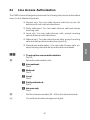
Operation
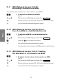
Accessing Special Services via
the Keypad
a/b-ISDN
You can only use special keypad features (for example to activate call forwarding through the office exchange) if they are supported by the local exchange
system installed by your network operator. If in doubt, please consult the
customer service department of your network operator and ask for instructions
on using the keypad. Also, your inhouse PABX system must be set up
accordingly to give inhouse parties access to special keypad features. Special
services are unavailable if the terminal attachment port is set up to acquire an
ISDN exchange line automatically, so you may have to disable that function
beforehand. In order for a terminal to access special services via the keypad,
you must allocate an MSN that is authorized to use those services.
51
Operation
25
25.1
Initiating Special Services via the Keypad
b
0
Pick up the handset. You will hear the inhouse dial tone.
Dial 0 or *0.
You will hear the office dial tone.
Operation
You have fully transparent access to the office exchange
system now. Any digits or characters you dial will be sent
directly to the office exchange to initiate a special service
offered by your network operator.
* or #
t
Dial * or #, as specified by your network operator.
Dial the necessary digits.
Depending on the service configuration used by your network
operator, you will receive an acknowledgement signal or an
error message from the office exchange. This may either be a
signal tone (analog and ISDN terminals) or a signal tone and a
text message appearing in the display window of your ISDN
telephone set.
a
Hang up.
52
elmeg C68 - elmeg C88
53
Setup
Setup
54
Setup
27
28
29
30
31
32
33
34
35
36
37
38
39
40
41
42
43
44
45
46
47
48
49
Basic Setup . . . . . . . . . . . . . . . . . . . . . . . .
Changing the Password . . . . . . . . . . . . . . . . . .
Reset . . . . . . . . . . . . . . . . . . . . . . . . . . . .
Exchange Line Acquisition Digits . . . . . . . . . . . . .
Changing Inhouse Extension Numbers . . . . . . . . . .
ISDN-Specific Settings -Point-to-Multi-point Access . . .
Line Preselection . . . . . . . . . . . . . . . . . . . . . .
Setup for Point-to-Point Access . . . . . . . . . . . . . .
Line Access Authorization . . . . . . . . . . . . . . . . .
Automatic ISDN Network Access Port Acquisition . . . .
Managing Call Distribution . . . . . . . . . . . . . . . . .
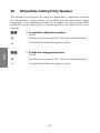
Show/Hide Calling Party Number . . . . . . . . . . . . .
Show/Hide Your Subscriber Number . . . . . . . . . . .
Service-Specific Call Forwarding Point-to-Multipoint Access . . . . . . . . . . . . . . . . .
Service-Specific Call Forwarding - Point-to-Point Access
Door Intercom Authorization . . . . . . . . . . . . . . . .
Central Abbreviated Dialing . . . . . . . . . . . . . . . .
Music on Hold . . . . . . . . . . . . . . . . . . . . . . .
Entering Date and Time . . . . . . . . . . . . . . . . . .
Call Statistics, Connection Charges . . . . . . . . . . . .
Toggling Keypad Control On and Off . . . . . . . . . . .
PC-Based Setup . . . . . . . . . . . . . . . . . . . . . .
Glossary of ISDN Terms . . . . . . . . . . . . . . . . . .
55
.
.
.
.
.
.
.
.
.
.
.
.
.
.
.
.
.
57
60
60
62
63
67
78
78
81
82
83
89
89
89
95
101
106
107
107
. 108
111
113
115
Setup
Setup . . . . . . . . . . . . . . . . . . . . . . . . . . . . . . . . . . 53
56
Setup
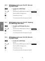
26
Basic Setup
a/b-ISDN
The setup can be performed by any party who is in possession of the password,
using any telephone set attached to the unit. When entering the ID codes given
in the following, avoid idle intervals of more than 10 seconds between any two
digits, else your entry will be automatically cancelled.
Caution! If the system returns an error signal, you will have to start over
with the setup.
b
Pick up the handset.
You will hear the inhouse dial tone.
**
q
====
Press the * key twice.
q
t
q
You will hear the acknowledgement signal.
Enter the four-digit password, for example 0000 (shipping
configuration).
Dial the ID code for the desired feature.
Wait for the acknowledgement signal, indicating that the
feature has been stored.
Note: You can now proceed to enter all ID codes for the features of your
choice. After entering an ID code, wait for the acknowledgement signal,
then enter the next ID code.
a
Hang up.
Caution!
!
The setup procedures described in the following require
that the ”Basic Setup” outlined above has been completed.
Please note that all ID codes are ”hard-wired” into the
system and cannot be changed.
57
Setup
You will hear the acknowledgement signal.
26.1
Recommended Setup Procedure
Table A: Setting up ISDN Network Access Ports
Setup
Item
Point-to-Multipoint Access and Point-to-Point Access
1
Set up one or two ISDN network access ports
2
Perform basic setup for point-to-multipoint access
(shipping configuration)
3
Continue with Table B Item 1
4
Perform basic setup for point-to-point access
5
Continue with Table C Item 1
Page
127
67
78
Table B: Multiple Subscriber Numbers
Item
Point-to-Multipoint Access
Page
1
Allocate multiple subscriber numbers to terminal
equipment
68
2
Set up MSN call distribution
74
3
Continue with Table C Item 1
Table C: Features
Item
Point-to-Multipoint Access and Point-to-Point Access
Page
1
Configure line access authorization for terminals
81
2
Select manual or automatic exchange line acquisition
82
3
Configure call distribution lists
82
4
Enable/disable calling line identification
90
5
Configure line preselection
78
6
Configure abbreviated dialing
58
108
Item
Point-to-Multipoint Access and Point-to-Point Access
Page
Door intercom
103
8
Music on hold
109
9
Date and time
110
10
Call statistics/connection charges
111
11
Change the password
60
12
Service-specific call forwarding -point-to-multipoint
91
13
Service-specific call forwarding -point-to-point
97
Setup
7
59
27
Changing the Password
The password permits access to the setup mode or password-protected
operations. You must enter the new four-digit password twice (default is 0000).
92
To change the password:
Dial 92.
t
t
q
Enter the four digits for the new password.
Reenter the four digits for the new password to confirm.
You will hear the acknowledgement signal.
Setup
Note:
In case you have forgotten your password, you must perform a general
hardware reset to restore your PABX system to the shipping configuration.
28
Reset
Resetting restores the PABX system to a well-defined initial state, for example
to the shipping configuration (see page 8 ). You may need this option if you
wish to cancel an undesired setup or perform a system setup ”from scratch”.
28.1
Hardware Reset to the Shipping Configuration
Unplug the 230V AC power plug of the PABX system from the wall outlet. Open
switch S02. Wait approx. one minute, close switch S02 again, then plug the
power cord back in. Your PABX system has now been reset to the shipping
configuration (see page 8). You will also need this reset procedure if you have
forgotten your password.
60
28.2
90
Software Reset to the Shipping Configuration
• To restore the PABX system to the shipping configuration:
Dial 90.
The unit will reset now.
28.3
91
Resetting Selected Extensions
• To cancel the features (call rerouting, callback and ISDN
line reservation) stored by your PABX system for a selected
inhouse extension:
Dial 91.
28.4
91*
Dial the desired inhouse extension number.
You will hear the acknowledgement signal.
Resetting all Inhouse Extensions
• To cancel the features (call rerouting, callback and ISDN
line reservation) stored by your PABX system for all inhouse
extensions:
Dial 91.
q
You will hear the acknowledgement signal.
61
Setup
t
q
29
Exchange Line Acquisition Digits
When shipped from the factory, the unit is preset to acquire an unused ISDN
exchange line when the user dials *= or =. The setup gives you the option
to choose any exchange line acquisition digit between = and ). This digit is
valid for all ISDN network accesss ports.
Caution! Inhouse extension numbers and exchange line acquisition codes
may not have the same leading digit. For example, you cannot use inhouse
extension numbers with a leading ”9" if an outbound ISDN line is accessed
with the exchange line acquisition digit ”9".
Setup
29.1
00
Deleting a Custom Exchange Line Acquisition Digit
• To delete the exchange line acquisition digit:
Dial 00.
*
q
Terminate your entry.
You will hear the acknowledgement signal.
To access an outbound ISDN line, you will now have to dial the
default *0.
29.2
00
Changing the Exchange Line Acquisition Digit
• To change the exchange line acquisition digit:
Dial 00.
=x)
Enter a new digit (0...9)
q
You will hear the acknowledgement signal.
62
30
Changing Inhouse Extension
Numbers
30.1
Terminal Extension Numbers (Shipping
Configuration)
Table 1 - Default Inhouse Extension Numbers
Inhouse ISDN and
analog ports
Default inhouse extension
numbers
ISDN port #1
10...19
ISDN port # 2
20...29
ISDN port # 3
30...39
Analog ports
40...47
Caution! Inhouse extension numbers and exchange line acquisition
codes cannot have the same leading digit. For example, you will not be
able to use inhouse extension numbers with a leading ”9" if the outbound ISDN line is accessed with the exchange line acquisition digit ”9".
We strongly recommend that you enter at least one new terminal extension
number, else you will be unable to make calls and set up the unit after exiting from the setup mode. If this happens, your only option is a general
hardware reset.
63
Setup
Your PABX system has a built-in set of extension numbers. When shipped from
the factory, the unit is preset to use the inhouse extension numbers listed in
the table below. You can allocate inhouse extension numbers between 00 and
99 (see page 64), as required for your communications environment. Please
avoid duplicate extension numbers. You can select any exchange line acquisition digit between 0 and 9.
When shipped from the factory, the analog ports and inhouse ISDN ports of
the unit are preset to use the extension numbers listed in table 1 below. Before
you enter a new extension number, you need to delete the existing extension
number. When doing so, please note that all existing entries in Day/Night and
door intercom call distribution lists and the MSN allocations will be deleted in
the process.
30.2
Deleting Inhouse Extension Numbers
(Analog & ISDN)
Deleting an inhouse extension number deletes all entries in the Day/Night and
door intercom call distribution lists.
01
• To delete an inhouse extension number:
Setup
Dial 01.
t
Delete one terminal extension number (00...99).
or
or
*
q
Delete all terminal extension numbers.
30.3
03
You will hear the acknowledgement signal.
Changing Extension Numbers for Analog Terminals
• To change an inhouse extension number:
Dial 03.
!x(
Select the port number (see cable terminal numbering in the
chapter Installation for reference).
t
q
Select a new terminal extension number (00...99).
30.4
07
You will hear the acknowledgement signal.
Identifying Analog Terminals
• To identify the type of analog terminal:
Dial 07.
!x(
Select the port number (see cable terminal numbering in the
chapter Installation for reference).
t
Select the type of terminal attached to the analog port.
0
1
2
Analog port not in use
Telephone set
Call answering machine
64
3
4
5
6
7
q
Modem
Group 3 telefax
Multifunctional set
Analog port # 7: music on hold (external audio insertion)
Analog port # 8: door intercom
You will hear the acknowledgement signal.
1x5
Dialing method defaults to tone dialing.
0x5,7
Change only if there is no feature currently selected for the
extension number allocated to this port.
6
Deletes the extension number, disabling the port for terminal
attachment.
7
Sets the authorization level to inhouse only, deleting the
extension number from the Day/Night and door intercom call
distribution lists and disabling the port for terminal attachment.
30.5
Analog Terminal Dialing Method
When shipped from the factory, the analog ports are preset to use tone dialing.
Please note that when resetting any port to pulse dialing, this will disable all
features that are initiated with the * key.
08
• To change the dialing method:
Dial 08.
!x(
Select the port number (see cable terminal numbering in the
chapter Installation for reference).
t
1
2
q
Select the dialing method.
Pulse dialing
Tone dialing
You will hear the acknowledgement signal.
65
Setup
Notes on the setup items 0x7.
30.6
Changing ISDN Terminal Extension
Number Allocations
When shipped from the factory, the inhouse ISDN ports are preset to use the
extension numbers listed in table 1 on page 63. You can allocate up to 10
extension numbers to each inhouse ISDN bus port. These extension numbers
need to be stored as MSNs in the attached ISDN terminals. You can also use
these extension numbers as an MSN for several terminals attached to an
inhouse ISDN port.
02
• To enter a new ISDN extension number:
Dial 02.
Dial the extension number (00...99) for the desired terminal.
You will hear the acknowledgement signal.
Setup
!x
q
66
31
ISDN-Specific Settings Point-to-Multi-point Access
The following sections outline the setup for special features offered by the
point-to-multipoint ISDN access. When shipped from the factory, the unit is
already configured for point-to-multipoint access operation.
31.1
Basic Setup for Point-to-Multipoint Access Operation
The current version of the on-board software provides the option to set up both
or each one of the ISDN network access ports for different access modes
(point-to-point or point-to-multipoint).
• Setting Up ISDN Network Access Ports
(Port #1and #2):
Dial 10#.
q
You will hear the acknowledgement signal.
The unit will reset now.
• Setting Up ISDN Network Access Port #1:
101*
Point-to-point:
Dial 101*.
101#
Point-to-multipoint:
Dial 101#.
q
You will hear the acknowledgement signal.
The unit will reset now.
• Setting Up ISDN Network Access Port #2:
102*
Point-to-point:
Dial 102*.
102#
Point-to-multipoint:
Dial 102#.
q
You will hear the acknowledgement signal.
The unit will reset now.
67
Setup
10#
31.2
Allocating Multiple Subscriber Numbers
(MSN)
You can allocate up to 8 terminals to each MSN (ISDN or analog terminals).
External callers can reach these terminals via the ISDN network access ports
of the unit. If an external subscriber dials an MSN, the incoming call will make
these terminals ring, provided there is a match of service.
If an MSN is allocated to a call distribution list, incoming calls will make all
matching terminals on that list ring.
Setup
An MSN entry can be changed at any time without any need for prior deletion.
The network operator will notify you of your multiple subscriber numbers (MSN).
As a general rule, you will receive 3 MSNs. Some network operators may
provide you with more numbers, up to a maximum of ten. Enter your multiple
subscriber numbers and the pertinent terminals (8 max.) or call distribution lists
(MSN) in the following table.
Do not forget to fill in the following table, since it is frequently referenced in the
following setup instructions.
68
Tabelle 2
Digit
ISDN Port #1
MSN
ISDN Port #2 (if in use)
Terminal/CDL
Terminal/CDL
0
1
2
Setup
3
4
5
6
7
8
9
69
31.3
14
ISDN Network Access Port #1: Allocating MSN Digits
• To allocate an MSN digit:
Setup
Dial 14.
=x)
t
#
Dial the desired MSN digit (see table 2 on page 69 ).
q
You will hear the acknowledgement signal.
Enter the MSN (16 digits max.).
Terminate your entry.
31.4
ISDN Network Access Port #1: Deleting
the MSN Digit Allocation
14
• To delete an MSN digit allocation:
Dial 14.
=x)
#
Dial the desired MSN digit (see table 2 on page 69 ).
q
You will hear the acknowledgement signal.
31.5
15
Delete the allocation.
ISDN Network Access Port #2: Allocating MSN Digits
• To allocate an MSN digit:
Dial 15.
=x)
t
#
Dial the desired MSN digit (see table 2 on page 69 ).
q
You will hear the acknowledgement signal.
Enter the MSN (16 digits max.).
Terminate your entry.
70
31.6
15
ISDN Network Access Port #2:
Deleting the MSN Digit Allocation
• To delete the MSN digit allocation :
Dial 15.
=x)
#
Dial the desired MSN digit (see table 2 on page 69 ).
q
You will hear the acknowledgement signal.
31.7
Cancel the allocation.
ISDN Network Access Port #2:
Allocating Terminals to an MSN
16
• To allocate terminals to an MSN:
Dial 16.
=x)
t
q
31.8
16
Dial the desired MSN digit (see table 2 on page 69 ).
Dial the extension number (00...99) for the desired terminal.
You will hear the acknowledgement signal.
ISDN Network Access Port #1:
Allocation of a Call Distribution List to
an MSN
• To allocate a call distribution list to an MSN:
Dial 16.
=x)
*
q
Dial the desired MSN digit (see table 2 on page 69 ).
Press the * key to confirm your entry.
You will hear the acknowledgement signal.
The allocation of terminals to an MSN has been deleted now.
71
Setup
You can allocate a maximum of 8 terminals to each MSN.
31.9
ISDN Network Access Port #2:
Allocating Terminals to an MSN
You can allocate a maximum of 8 terminals to each MSN.
17
• To allocate terminals to an MSN:
Dial 17.
=x)
t
q
Dial the desired MSN digit (see table 2 on page 69 ).
Dial the extension number (00...99) for the desired terminal.
You will hear the acknowledgement signal.
Setup
31.10 ISDN Network Access Port #2: Allocation of an MSN to a Call Distribution List
17
• To allocate an MSN to a call distribution list:
Dial 17.
=x)
*
q
Dial the desired MSN digit (see table 2 on page 69 ).
Press the * key to confirm your entry.
You will hear the acknowledgement signal.
The allocation of terminals to an MSN has been deleted now.
31.11 ISDN Network Access Port #1: Deleting
the Allocation of a Terminal to an MSN
18
• To delete the allocation of a terminal to an MSN:
Dial 18.
=x)
t
q
Dial the desired MSN digit (see table 2 on page 69 ).
Dial the extension number (00...99) for the desired terminal.
You will hear the acknowledgement signal.
72
31.12 ISDN Network Access Port #1: Deleting
the Allocation of All Terminals to an
MSN
18
• To delete the allocation of all terminals to an MSN :
Dial 18.
=x)
*
q
Dial the desired MSN digit (see table 2 on page 69 ).
Press the * key to confirm your entry.
You will hear the acknowledgement signal.
31.13 ISDN Network Access Port #2: Deleting
the Allocation of a Terminal to an MSN
19
• To delete the allocation of a terminal to an MSN:
Dial 19.
=x)
t
q
Dial the desired MSN digit (see table 2 on page 69 ).
Dial the extension number (00...99) for the desired terminal.
You will hear the acknowledgement signal.
31.14 ISDN Network Access Port #2: Deleting
the Allocation of all Terminals to an MSN
19
• To delete the allocation of all terminals to an MSN :
Dial 19.
=x)
*
q
Dial the desired MSN digit (see table 2 on page 69 ).
Press the * key to confirm your entry.
You will hear the acknowledgement signal.
Note:
After the allocation of all terminals to an MSN has been deleted, the only remaining allocation is the one between the MSN and the call distribution list.
73
Setup
Note:
When the allocation of all terminals to an MSN has been deleted, the only
remaining allocation is the one between the MSN and the call distribution
list.
32
MSN Signaling
When shipped from the factory, your PABX system is not preset to send MSN
information to the office exchange. You network operator will bill the connection
charges for all terminals to a single MSN, referred to as the ”Default MSN”.
Setup
However, your PABX system has the ability to send a selected MSN to the
office exchange when establishing an outbound ISDN connection, allowing the
network operator to create a detailed record of connection charges for that
MSN. However, if terminals do not have an MSN allocation the PABX system
will not include the MSN into the signalling information sent to the office
exchange.
In Table 3, use the first column to enter the extension numbers of the terminals
whose MSN you wish to have sent to the office exchange. In the second and
third columns, enter the number allocation of the selected MSN from Table 2
(page 69 ). Table 3 should now contain the following information:
The PABX system includes the MSN allocated to the inhouse terminals listed
below when exchanging signaling information with the office exchange.
74
Table 3
MSN digit ISDN network
access port #1
0...9
MSN digit ISDN network
access port #2
0...9
Line
preselection
0
1
2
Setup
Inhouse
extension
number
75
MSN digit ISDN network
access port #1
0...9
Setup
Inhouse
extension
number
76
MSN digit ISDN network
access port #2
0...9
Line
preselection
0
1
2
32.1
30
MSN Signaling - ISDN Network Access
Port #1
• To allocate a terminal to ISDN network access port #1:
Dial 30.
=x)
t
Dial the desired MSN digit (see table 3, page 75).
q
32
You will hear the acknowledgement signal.
Dial the extension number (00...99) for the desired terminal.
• To delete the allocation of a terminal to ISDN port #1:
t
Dial the extension number (00...99) for the desired terminal.
q
You will hear the acknowledgement signal.
32.2
31
MSN Signaling - ISDN Network Access
Port #2
• To allocate a terminal to ISDN access port #2:
Dial 31.
=x)
t
Dial the desired MSN digit (see table 3 on page75 ).
q
33
You will hear the acknowledgement signal.
Dial the extension number (00...99) for the desired terminal.
• To delete the allocation of a terminal to ISDN port #2:
Dial 33.
t
Dial the extension number (00...99) for the desired terminal.
q
You will hear the acknowledgement signal.
77
Setup
Dial 32.
32.3
Line Preselection
The line preselection setup is based on information contained in table 3 (see
page 75). Table 3 determines the usage of line #1, #2 or # 0 (both lines) when
a terminal accesses an outbound line.
32.4
Line Preselection for the ISDN Network
Access Ports #1 and #2
21
• To identify the type of analog terminal:
Setup
Dial 21.
0
Line 0. Use any idle ISDN port (ISDN network access
port #1 or #2).
1
2
t
q
Line 1. Use ISDN network access port #1.
33
Setup for Point-to-Point Access
Line 2. Use ISDN network access port #2.
Dial the extension number (00...99) for the desired terminal.
You will hear the acknowledgement signal.
The current version of the on-board software provides the option to set up both
or each one of the ISDN network access ports for different access modes
(point-to-point or point-to-multipoint).
10*
• Setting Up ISDN Network Access Ports
(Port #1and #2):
Dial 10*.
q
You will hear the acknowledgement signal.
The unit will reset now.
• Setting Up ISDN Network Access Port #1:
101*
Point-to-point:
Dial 101*.
78
101#
Point-to-multipoint:
Dial 101#.
q
You will hear the acknowledgement signal.
The unit will reset now.
• Setting Up ISDN Network Access Port #2:
102*
Point-to-point:
Dial 102*.
102#
Point-to-multipoint:
Dial 102#.
q
You will hear the acknowledgement signal.
33.1
11
ISDN Network Access Port #1:
Entering the DDI Root Number
• To enter the direct dial-in root number:
Dial 11.
t
#
q
33.2
Enter the DDI root number (skip area code and DDI suffixes).
Terminate your entry by pressing the # key.
You will hear the acknowledgement signal.
ISDN Network Access Port #1:
Deleting the DDI Root Number
11
To delete the direct dial-in root number:
Dial 11.
#
q
Terminate your entry by pressing the # key.
You will hear the acknowledgement signal.
79
Setup
The unit will reset now.
33.3
12
ISDN Network Access Port #2:
Entering the DDI Root Number
• To enter the direct dial-in root number:
Dial 12.
t
Enter the DDI root number (skip area code and direct dial-in
suffixes).
#
q
Terminate your entry by pressing the # key.
Setup
33.4
12
You will hear the acknowledgement signal.
ISDN Network Access Port #2:
Deleting the DDI Root Number
• To delete the direct dial-in root number:
Dial 12.
#
q
Terminate your entry by pressing the # key.
You will hear the acknowledgement signal.
80
34
Line Access Authorization
The PABX system distinguishes between the following line access authorization
levels for the attached terminals:
• Inhouse only. You can make inhouse calls but you are not
authorized to call external subscribers.
• Partly authorized. You can make inhouse calls and accept
incoming calls.
• Local only. You can make inhouse calls, accept incoming
calls and dial up local subscribers.
• National only. You can make inhouse calls, accept incoming
calls and dial up national subscribers (prefix 0).
• International authorization. You can make inhouse calls, ac-
20
• To set up line access authorization:
Dial 20.
t
t
q
Select the authorization level.
0
International:
Dial 0.
1
National:
Dial 2.
2
Local :
Dial 2.
3
Partly authorized:
Dial 3.
4
Inhouse only:
Dial 4.
Dial the extension number (00...99) for the desired terminal.
You will hear the acknowledgement signal.
81
Setup
cept incoming calls and dial up subscribers worldwide.
34.1
Automatic ISDN Network Access Port
Acquisition
This feature enables (and disables) terminals to automatically acquire a preselected ISDN network access port.
23
• To enable automatic ISDN port acquisition:
Dial 23.
t
q
22
Dial the extension number (00...99) for the desired terminal.
You will hear the acknowledgement signal.
• To disable automatic ISDN port acquisition:
Dial 22.
Dial the extension number (00...99) for the desired terminal.
You will hear the acknowledgement signal.
Setup
t
q
35
Managing Call Distribution
35.1
Call Distribution Control -Day/Night and
Door Intercom
This authorization enables terminals to select the Day/Night and the door
intercom call distribution lists.
27
• To allow terminals to control Day/Night and door intercom call distribution:
Dial 27.
t
q
26
Dial the extension number (00...99) for the desired terminal.
You will hear the acknowledgement signal.
• To disallow terminals to control Day/Night and door
intercom call distribution :
Dial 26.
t
q
Dial the extension number (00...99) for the desired terminal.
You will hear the acknowledgement signal.
82
35.2
Selecting Call Distribution List #1 (Day)
This feature enables terminals which are authorized to perform the setup (and
users in possession of the password) to select call distribution list #1. The call
distribution lists #1 and #2 can only be toggled and never be active at the same
time.
401
• To select call distribution list #1 :
Dial 401.
35.3
You will hear the acknowledgement signal.
Selecting Call Distribution List #2 (Night)
This feature enables terminals which are authorized to perform the setup to
select call distribution list #2. The call distribution lists #1 and #2 can only be
toggled and never be active at the same time.
402
• To select call distribution list #2:
Dial 402.
q
35.4
You will hear the acknowledgement signal.
Call Distribution List #1:
Entering Service-Specific Terminals
Terminals are included in the call distribution list #1 according to the desired
service. The list may contain a maximum of six inhouse terminals.
42
• To include a service-specific inhouse extension in call
distribution list #1:
Dial 42.
t
t
q
Select the service:
1
Telephony
2
Data communications (ISDN terminals only)
3
Group 2/3 telefax
4
Group 4 telefax (ISDN terminals only).
Dial the extension number (00...99) for the desired terminal.
You will hear the acknowledgement signal.
83
Setup
q
35.5
Call Distribution List #1: Entering a Service-Specific External Subscriber
Number
You can enter a service-specific subscriber number into the call distribution list,
omitting the ISDN network access port acquisition digit. Please note that
entering a service-specific external subscriber number in the call distribution
list deletes existing extension numbers in the process, and vice versa.
42
• To enter a service-specific external subscriber number
into call distribution list #1:
Dial 42.
Setup
t
*
t
#
q
35.6
Select the service:
1
Telephony
2
Data communications (ISDN terminals only)
3
Group 2/3 telefax
4
Group 4 telefax (ISDN terminals only).
Confirm your entry.
Dial the external subscriber number.
Terminate your entry by pressing the # key.
You will hear the acknowledgement signal.
Call Distribution List #1:
Deleting Service-Specific Terminals
The following instructions outline how to delete service-specific terminals from
call distribution list #1.
41
• To delete a service-specific inhouse extension fromcall
distribution list #1:
Dial 41.
t
Select the service:
1
Telephony
2
Data communications (ISDN terminals only)
3
Group 2/3 telefax
84
4
t
q
35.7
Group 4 telefax (ISDN terminals only).
Dial the extension number (00...99) for the desired terminal.
You will hear the acknowledgement signal.
Call Distribution List #1: Deleting All Service-Specific Terminals or the External
Subscriber Number
This action deletes all terminals or the external subscriber number from call
distribution list #1, going by service.
41
• To delete service-specific extensions or an external
subscriber number from call distribution list #1:
Dial 41.
*
q
Select the service:
Setup
t
1
Telephony
2
Data communications (ISDN terminals only)
3
Group 2/3 telefax
4
Group 4 telefax (ISDN terminals only).
Terminate your entry by pressing the * key.
You will hear the acknowledgement signal.
85
35.8
Call Distribution List #1:
Allocating Connection Charges
If call distribution list #1 contains an external subscriber number, any incoming
calls with a matching service will be automatically rerouted to that number, and
the connection charges incurred by this rerouted call are charged to the
account of a dedicated inhouse extension. This extension cannot be deleted,
it can only be overwritten.
43
• To allocate the connection charges to a selected extension:
Dial 43.
Setup
t
t
q
35.9
Select the service:
1
Telephony
2
Data communications (ISDN terminals only)
3
Group 2/3 telefax
4
Group 4 telefax (ISDN terminals only).
Dial the extension number (00...99) for the desired terminal.
You will hear the acknowledgement signal.
Call Distribution List #2:
Entering Service-Specific Terminals
A maximum of six inhouse terminals can be included in the call distribution list
#2, according to the desired service.
45
• To include a service-specific inhouse extension in call
distribution list #2:
Dial 45.
t
Select the service:
1
Telephony
2
Data communications (ISDN terminals only)
3
Group 2/3 telefax
4
Group 4 telefax (ISDN terminals only).
86
t
q
Dial the extension number (00...99) for the desired terminal.
You will hear the acknowledgement signal.
35.10 Call Distribution List #2: Entering a Service-Specific External Subscriber
Number
You can enter a service-specific subscriber number into the call distribution list,
omitting the ISDN network access port acquisition digit. Please note that
entering a service-specific external subscriber number in the call distribution
list deletes existing extension numbers in the process, and vice versa.
45
• To enter a service-specific external subscriber number
t
*
t
#
q
Setup
into call distribution list #2:
Dial 45.
Select the service:
1
Telephony
2
Data communications (ISDN terminals only)
3
Group 2/3 telefax
4
Group 4 telefax (ISDN terminals only).
Confirm your entry by pressing the * key.
Dial the external subscriber number.
Terminate your entry by pressing the # key.
You will hear the acknowledgement signal.
35.11 Call Distribution List #2:
Deleting Service-Specific Terminals
The following instructions outline how to delete service-specific terminals from
call distribution list #2.
44
• To delete a service-specific inhouse extension from call
distribution list #2:
Dial 44.
87
t
t
q
Select the service:
1
Telephony
2
Data communications (ISDN terminals only)
3
Group 2/3 telefax
4
Group 4 telefax (ISDN terminals only).
Dial the extension number (00...99) for the desired terminal.
You will hear the acknowledgement signal.
Setup
35.12 Call Distribution List #2: Deleting All Service-Specific Terminals or the External
Subscriber Number
This action deletes all terminals or the external subscriber number from call
distribution list #2, going by service.
44
• To delete service-specific extensions or an external
subscriber number from call distribution list #2:
Dial 44.
t
*
q
Select the service:
1
Telephony
2
Data communications (ISDN terminals only)
3
Group 2/3 telefax
4
Group 4 telefax (ISDN terminals only).
Terminate your entry by pressing the * key.
You will hear the acknowledgement signal.
35.13 Call Distribution List #2:
Allocating Connection Charges
If call distribution list #2 contains an external subscriber number, any incoming
calls with a matching service will be automatically rerouted to that number, and
the connection charges incurred by this rerouted call are charged to the
account of a dedicated inhouse extension. This extension cannot be deleted,
88
it can only be overwritten.
46
• To allocate the connection charges to a selected extension:
Dial 46.
t
q
Select the service:
1
Telephony
2
Data communications (ISDN terminals only)
3
Group 2/3 telefax
4
Group 4 telefax (ISDN terminals only).
Dial the extension number (00...99) for the desired terminal.
You will hear the acknowledgement signal.
Setup
t
89
36
Show/Hide Calling Party Number
This feature, also referred to as calling line identification, suppresses or allows
the transmission of your number via the ISDN network access port. When
suppressed, your subscriber number will be hidden from any external ISDN
subscriber you are calling, that is it will not appear on the display of his or her
terminal.
28
• To show the calling party number:
Dial 28.
t
Dial the extension number (00...99) for the desired terminal.
q
You will hear the acknowledgement signal.
Setup
29
• To hide the calling party number:
Dial 29.
t
q
Dial the extension number (00...99) for the desired terminal.
You will hear the acknowledgement signal.
90
37
Show/Hide Your Subscriber
Number
38
To show your subscriber number (default setting):
Dial 38.
or
or
39
To hide your subscriber number:
Dial 39.
t
q
Dial the desired inhouse extension number (00...99).
38
You will hear the acknowledgement signal.
Service-Specific Call Forwarding Point-to-Multipoint Access
Some office exchange systems are able to forward the services printed in gray
(for example 20) in addition to the default services.
38.1
Immediate Call Forwarding
a/b-ISDN
Call forwarding occurs without delay upon reception of a call. The terminal
addressed originally will not ring.
61
ISDN port #1, immediate call forwarding:
Dial 61.
or
or
64
ISDN port #2, immediate call forwarding:
Dial 64.
91
Setup
This feature lets you select whether you want to have your own subscriber
number displayed on the remote terminal of the calling party or not. When you
choose to suppress your subscriber number, it will not be sent to the caller and
will not appear on the display of his or her telephone set. For example, if you
have forwarded your incoming calls to another terminal, the caller will not see
any subscriber number.
t
Select the service you wish to forward.
00
All services
01
Telephony (including services 10, 11,12 and 20)
Setup
02 Telefax (including services 11, 20 and 21)
03
Data communications
10
Speech
11
Audio 3k1Hz (including service 20 )
12
Telephony 3k1Hz
20
Group 2/3 telefax (including service 11 )
21
Group 4 telefax
=x)
Dial the digit for the group of extensions to be forwarded (see
table 2 on page 69 ) or press the * key to forward all MSNs at
that ISDN network access port .
t
#
q
Enter the external subscriber number.
a
Hang up.
38.2
Terminate your entry.
You will hear the acknowledgement signal for approx. one
second, followed by the special dial tone.
Cancelling Immediate Call Forwarding
a/b-ISDN
You can cancel immediate call forwarding in the office exchange for selected
services or all services (dial 00 for all services).
61
ISDN port #1, immediate call forwarding:
Dial 61.
or
or
64
ISDN port #2, immediate call forwarding:
Dial 64.
t
Select the service you wish to cancel forwarding for:
00
All services
92
Telephony (including services 10, 11,12 and 20)
02
Telefax (including services 11, 20 and 21)
03
Data communications
10
Speech
11
Audio 3k1Hz (including service 20 )
12
Telephony 3k1Hz
20
Group 2/3 telefax (including service 11 )
21
Group 4 telefax
=x)
Dial the desired MSN digit (see table 2 on page 69) or press the
* key to cancel all MSNs at that ISDN network access port.
#
q
Terminate your entry.
38.3
You will hear the acknowledgement signal for approx. one
second, followed by the inhouse dial tone.
Delayed Call Forwarding
a/b-ISDN
An incoming call will make the called terminal ring for approx. 15 seconds before
being forwarded to the selected destination. The terminal addressed originally
will stop ringing.
62
ISDN port #1, delayed call forwarding:
Dial 62.
or
or
65
ISDN port #2, delayed call forwarding:
Dial 65.
t
Select the service you wish to forward:
00
All services
01
Telephony (including services 10, 11,12 and 20)
02
Telefax (including services 11, 20 and 21)
03
Data communications
93
Setup
01
Setup
10
Speech
11
Audio 3k1Hz (including the services 20 )
12
Telephony 3k1Hz
20
Group 2/3 telefax (including service 11 )
21
Group 4 telefax
=x)
Dial the desired MSN digit (see table 2 on page 69 ) or press the
* key to forward all MSNs at that ISDN network access port.
t
#
q
Enter the external subscriber number.
38.4
Terminate your entry.
You will hear the acknowledgement signal for approx. one
second, followed by the special dial tone.
Cancelling Delayed Call Forwarding
a/b-ISDN
You can cancel delayed call forwarding in the office exchange for selected
services or all services (dial 00 for all services).
62
ISDN port #1, delayed call forwarding:
Dial 62.
or
or
65
ISDN port #2, delayed call forwarding:
Dial 65.
t
Select the service to be cancelled:
00
All services
01
Telephony (including services 10, 11,12 and 20)
02
Telefax (including services 11, 20 and 21)
03
Data communications
10
Speech
11
Audio 3k1Hz (including service 20 )
12
Telephony 3k1Hz
94
20
Group 2/3 telefax (including service 11 )
21
Group 4 telefax
=x)
Dial the desired MSN digit (see table 2 on page 69 ) or press the
* key to cancel all MSNs at that ISDN network access port.
#
q
Terminate your entry.
38.5
You will hear the acknowledgement signal for approx. one
second, followed by the inhouse dial tone.
Call Forwarding on Busy
a/b-ISDN
63
ISDN port #1, call forwarding on busy:
Dial 63.
or
or
66
ISDN port #2, call forwarding on busy:
Dial 66.
t
Select the service you wish to forward
=x)
00
All services
01
Telephony (including services 10, 11,12 and 20)
02
Telefax (including services 11, 20 and 21)
03
Data communications
10
Speech
11
Audio 3k1Hz (including service 20 )
12
Telephony 3k1Hz
20
Telefax Gruppe 2/3 (including service 11 )
21
Group 4 telefax
Dial the desired MSN digit (see table 2 on page 69 )
or press the * key to forward all MSNs.
95
Setup
When the point-to-multipoint access is busy, calls will be immediately forwarded to the selected destination.
t
#
q
38.6
Enter the external subscriber number.
Terminate your entry.
You will hear the acknowledgement signal for approx. one
second, followed by the special dial tone.
Cancelling Call Forwarding on Busy
a/b-ISDN
Setup
You can cancel call forwarding on busy in the office exchange for selected
services or all services (dial 00 for all services).
63
ISDN port #1, call forwarding on busy:
Dial 63.
or
or
66
ISDN port #2, call forwarding on busy:
Dial 66.
t
Select the service to be cancelled:
00
All services
01
Telephony (including services 10, 11,12 and 20)
02
Telefax (including services 11, 20 and 21)
03
Data communications
10
Speech
11
Audio 3k1Hz (including service 20 )
12
Telephony 3k1Hz
20
Group 2/3 telefax (including service 11 )
21
Group 4 telefax
=x)
Dial the desired MSN digit (see table 2 on page 69) or press the
* key to cancel all MSNs.
#
q
Terminate your entry.
You will hear the acknowledgement signal for approx. one
second, followed by the inhouse dial tone.
96
39
Service-Specific Call Forwarding Point-to-Point Access
With a point-to-point access all incoming calls are forwarded independent of
direct dial-in numbers. Please note that some office exchange systems are able
to forward the services printed in italics and gray (for example 20) in addition
to the default services.
39.1
Point-to-Point Access: Immediate
Call Forwarding
a/b-ISDN
61
ISDN port #1, immediate call forwarding :
Dial 61.
or
or
64
ISDN port #2, immediate call forwarding:
Dial 64.
t
Select the service you wish to forward:
t
#
q
00
All services
01
Telephony (including services 10, 11,12 and 20)
02
Telefax (including services 11, 20 and 21)
03
Data communications
10
Speech
11
Audio 3k1Hz (including service 20 )
12
Telephony 3k1Hz
20
Group 2/3 telefax (including service 11 )
21
Group 4 telefax
Enter the external subscriber number.
Terminate your entry.
You will hear the acknowledgement signal for approx. one
second, followed by the special dial tone.
97
Setup
Calls are forwarded immediately upon reception. The terminal addressed
originally will not ring.
39.2
Cancelling Immediate Call Forwarding
a/b-ISDN
You can cancel call immediate forwarding in the office exchange for selected
services or all services (dial 00 for all services).
ISDN port #1, immediate call forwarding :
Dial 61.
or
or
64
ISDN port #2, immediate call forwarding:
Dial 64.
t
Select the service to be cancelled:
Setup
61
#
q
00
All services
01
Telephony (including services 10, 11,12 and 20)
02
Telefax (including services 11, 20 and 21)
03
Data communications
10
Speech
11
Audio 3k1Hz (including service 20 )
12
Telephony 3k1Hz
20
Group 2/3 telefax (including service 11 )
21
Group 4 telefax
Terminate your entry.
You will hear the acknowledgement signal for approx. one
second, followed by the inhouse dial tone.
98
39.3
Delayed Call Forwarding
a/b-ISDN
62
ISDN port #1, delayed call forwarding:
Dial 62.
or
or
65
ISDN port #2, delayed call forwarding:
Dial 65.
t
Select the service you wish to forward:
t
#
q
00
All services
01
Telephony (including services 10, 11,12 and 20)
02
Telefax (including services 11, 20 and 21)
03
Data communications
10
Speech
11
Audio 3k1Hz (including service 20 )
12
Telephony 3k1Hz
20
Group 2/3 telefax (including service 11 )
21
Group 4 telefax
Enter the external subscriber number.
Terminate your entry.
You will hear the acknowledgement signal for approx. one
second, followed by the special dial tone.
99
Setup
An incoming call will make the called terminal ring for approx. 15 seconds before
being forwarded to the selected destination. The terminal addressed originally
will stop ringing.
39.4
Cancelling Delayed Call Forwarding
a/b-ISDN
You can cancel delayed call forwarding in the office exchange for selected
services or all services (dial 00 for all services).
ISDN port #1, delayed call forwarding:
Dial 62.
or
or
65
ISDN port #2, delayed call forwarding:
Dial 65.
t
Select the service to be cancelled:
Setup
62
00
All services
01
Telephony (including services 10, 11,12 and 20)
02
Telefax (including services 11, 20 and 21)
03
Data communications
10
Speech
11
Audio 3k1Hz (including service 20 )
12
Telephony 3k1Hz
20
Group 2/3 telefax (including service 11 )
21
Group 4 telefax
#
q
Terminate your entry.
a
Hang up.
You will hear the acknowledgement signal for approx. one
second, followed by the inhouse dial tone.
100
39.5
Call Forwarding on Busy
a/b-ISDN
63
ISDN port #1, call forwarding on busy:
Dial 63.
or
or
66
ISDN port #2, call forwarding on busy:
Dial 66.
t
Select the service you wish to forward:
t
o
#
q
00
All services
01
Telephony (including services 10, 11,12 and 20)
02
Telefax (including services 11, 20 and 21)
03
Data communications
10
Speech
11
Audio 3k1Hz (including service 20 )
12
Telephony 3k1Hz
20
Group 2/3 telefax (including service 11 )
21
Group 4 telefax
Enter the external subscriber number.
Terminate your entry.
You will hear the acknowledgement signal for approx. one
second, followed by the special dial tone.
101
Setup
With a point-to-point access, incoming calls are forwarded immediately upon
reception.
39.6
Cancelling Call Forwarding on Busy
a/b-ISDN
You can cancel call forwarding on busy in the office exchange for selected
services or all services (dial 00 for all services).
ISDN port #1, call forwarding on busy:
Dial 63.
or
or
66
ISDN port #2, call forwarding on busy:
Dial 66.
t
Select the service to be cancelled:
Setup
63
#
q
00
All services
01
Telephony (including services 10, 11,12 and 20)
02
Telefax (including services 11, 20 and 21)
03
Data communications
10
Speech
11
Audio 3k1Hz (including service 20 )
12
Telephony 3k1Hz
20
Group 2/3 telefax (including service 11 )
21
Group 4 telefax
Terminate your entry.
You will hear the acknowledgement signal for approx. 1
second, followed by the inhouse dial tone.
102
40
Door Intercom Authorization
a/b-ISDN
This feature requires that analog port #8 has been configured for door intercom
operation and that the equipment has been wired properly. When shipped from
the factory, the door intercom feature cannot access an outbound line.
Incoming doorbell calls override the inhouse-only limitation while the connection
exists.
40.1
Setup for Door Intercom Authorization
• The terminal can connect with the door intercom.
• The terminal can pick up a door intercom call.
• The terminal can actuate the door opener.
25
• To set up the door intercom authorization:
Dial 25.
t
q
40.2
24
Dial the extension number (00...99) for the desired terminal.
You will hear the acknowledgement signal.
Cancelling the Door Intercom Authorization
• To cancel the door intercom authorization:
Dial 24.
t
q
Dial the extension number (00...99) for the desired terminal.
You will hear the acknowledgement signal.
103
Setup
The door intercom authorization includes the following features:
40.3
Authorizing Terminals to Select the
Day/Night and Door Intercom Call Distribution Lists
This feature allows terminals to toggle the door intercom and the Day/Night call
distribution lists.
27
• To authorize a terminal to toggle the door intercom and
Day/Night call distribution lists:
Dial 27.
t
q
26
Dial the extension number (00...99) for the desired terminal.
You will hear the acknowledgement signal.
• To deny access to the door intercom and DayNight call
Setup
distribution list selection:
Dial 26.
t
q
40.4
Dial the extension number (00...99) for the desired terminal.
You will hear the acknowledgement signal.
Selecting Door Intercom Call Distribution List #1 (Day)
This feature enables terminals which are authorized to perform the setup to
toggle the door intercom call distribution list. The door intercom call distribution
lists #1 and #2 can only be toggled and never be active at the same time.
501
• To select door intercom call distribution list #1:
Dial 501.
q
40.5
You will hear the acknowledgement signal.
Selecting Door Intercom Call Distribution
List #2 (Night)
This feature enables terminals which are authorized to perform a setup to toggle
the door intercom call distribution list. The door intercom call distribution lists
#1 and #2 can only be toggled and never be active at the same time.
502
• To select door intercom call distribution list #2:
Dial 502.
104
q
40.6
You will hear the acknowledgement signal.
Door Intercom Call Distribution List #1:
Entering Inhouse Terminals
A maximum of 6 inhouse terminals can be entered into door intercom call
distribution list #1. The terminals on that list are automatically authorized to
receive door intercom calls.
52
• To add inhouse terminals to door intercom call distribution list #1:
Dial 52.
40.7
Dial the inhouse extension number (00...99).
You will hear the acknowledgement signal.
Door Intercom Call Distribution List #1:
Entering an External Subscriber Number
If an external subscriber number is entered in door intercom call distribution list
#1, the door intercom call is rerouted to that external party when a visitor rings
the doorbell. The charge units incurred by the rerouted call are charged to the
account of the door intercom extension number.
When entering an external subscriber number into the door intercom call
distribution list #1, omit the ISDN line acquisition digit. Doing so deletes all
extension numbers in that call distribution list.
52
• To enter an external subscriber number into door intercom call distribution list #1:
Dial 52.
*
t
#
q
Press the * key.
Dial the external subscriber number.
Terminate your entry by pressing the # key.
You will hear the acknowledgement signal.
105
Setup
t
q
40.8
Door Intercom Call Distribution List #1:
Deleting Inhouse Terminals
This procedure deletes a selected entry from the door intercom call distribution
list, cancelling the door intercom authorization in the process.
51
• To delete inhouse terminals from door intercom call
distribution list #1:
Dial 51.
t
q
Setup
40.9
Dial the inhouse extension number (00...99).
You will hear the acknowledgement signal.
Door Intercom Call Distribution List #1:
Deleting All Entries
This procedure deletes all entries from the door intercom call distribution list,
cancelling the door intercom authorization in the process.
51
• To delete all entries from door intercom call distribution
list #1:
Dial 51.
*
q
Terminate your entry by pressing the * key.
You will hear the acknowledgement signal.
40.10 Door Intercom Call Distribution List #2:
Entering Inhouse Terminals
A maximum of 6 inhouse terminals can be entered into door intercom call
distribution list #2. The terminals on that list are automatically authorized to
receive door intercom calls.
55
• To add inhouse terminals to door intercom call distribution list #2:
Dial 55.
t
q
Dial the inhouse extension number (00...99).
You will hear the acknowledgement signal.
106
40.11 Door Intercom Call Distribution List #2:
Entering an External Subscriber Number
If an external subscriber number is entered in door intercom call distribution list
#2, the door intercom call is rerouted to that external party when a visitor rings
the doorbell. The charge units incurred by the rerouted call are charged to the
account of the door intercom extension number.
When entering an external subscriber number into the door intercom call
distribution list #2, omit the ISDN line acquisition digit. Doing so deletes all
extension numbers in that call distribution list.
55
• To enter an external subscriber number into door intercom call distribution list #2:
Dial 55.
Terminate your entry by pressing the * key.
Dial the external subscriber number.
Terminate your entry by pressing the # key.
You will hear the acknowledgement signal.
40.12 Door Intercom Call Distribution List #2:
Deleting Inhouse Terminals
This procedure deletes a selected entry from the door intercom call distribution
list, cancelling the door intercom authorization in the process.
54
• To delete inhouse terminals from door intercom call
distribution list #2:
Dial 54.
t
q
Dial the inhouse extension number (00...99).
You will hear the acknowledgement signal.
107
Setup
*
t
#
q
40.13 Door Intercom Call Distribution List #2:
Deleting All Entries
This procedure deletes all entries from the door intercom call distribution list,
cancelling the door intercom authorization in the process.
54
• To delete all entries from door intercom call distribution list #2:
Dial 54.
Setup
*
q
41
Terminate your entry by pressing the * key.
You will hear the acknowledgement signal.
Central Abbreviated Dialing
When entering subscriber numbers, omit the exchange line acquisition digit.
41.1
Allocating External Subscriber Numbers
to Abbreviated Dialing Codes
77
• To allocate an external subscriber number to an
abbreviated dialing code:
Dial 77.
==x))
t
#
q
41.2
Select the abbreviated dialing code.
Enter the external subscriber number.
Terminate your entry by pressing the # key.
You will hear the acknowledgement signal.
Deleting an External Subscriber Number
77
• To delete the allocation of an external subscriber
number to an abbreviated dialing code :
Dial 77.
==x))
Select the abbreviated dialing code.
108
#
q
Terminate your entry by pressing the # key.
You will hear the acknowledgement signal.
41.3
Deleting All External Subscriber Numbers
77
• To delete all subscriber numbers:
Dial 77.
42
Terminate your entry by pressing the # key.
You will hear the acknowledgement signal.
Setup
#
q
Music on Hold
Your PABX system comes with two built-in tunes and an interface for an
external audio source. The setup allows for enabling/disabling the built-in music
on hold, provided external music on hold audio insertion is inactive.
970
Disables built-in music on hold (allowing for external audio
insertion).
971
972
q
Selects built-in music on hold, tune #1.
Selects built-in music on hold, tune #2.
You will hear the acknowledgement signal.
109
43
Entering Date and Time
Setup
When the unit is shipped from the factory or when it is powered down and
switch S02 is opened subsequently, the current time is the time of compilation
of the system software. This time is overridden by ISDN network time as soon
as the unit establishes the very first connection via the office exchange of your
network operator.
98
To enter date and time:
Dial 98.
=!x§!
=!x!"
)&x
==x"§
==x%)
q
Enter the day.
Enter the month.
Enter the year (for example 96).
Enter the hour.
Enter the minutes.
You will hear the acknowledgement signal.
The seconds count will start at 00 after the entry has been terminated.
110
44
Call Statistics, Connection
Charges
Call statistics for outbound calls can only be recorded using project numbers.
Enabling Call Statistics for Individual
Terminals
81
To enable call statistics for a selected terminal:
Dial 81.
t
q
Dial the desired extension number (00...99).
44.2
You will hear the acknowledgement signal.
Enabling Call Statistics for All Terminals
81
To enable call statistics for all terminals:
Dial 82.
*
q
Terminate your entry by pressing the * key.
44.3
You will hear the acknowledgement signal.
Disabling Call Statistics for Individual
Terminals
80
To disable call statistics for a selected terminal :
Dial 80.
t
q
Dial the extension number (00...99) for the desired terminal.
You will hear the acknowledgement signal.
111
Setup
44.1
44.4
Disabling Call Statistics Outputs via the
Serial Interface
82
To disable call statistics output:
Dial 82.
#
q
Terminate your entry by pressing the # key.
Setup
44.5
You will hear the acknowledgement signal.
Disabling Call Statistics for All Terminals
80
To disable call statistics for all terminals:
Dial 80.
*
q
Terminate your entry by pressing the * key.
You will hear the acknowledgement signal.
44.6
Enabling Call Statistics Outputs via the
Serial Interface
82
To enable call statistics outputs:
Dial 82.
*
q
Terminate your entry by pressing the * key.
44.7
You will hear the acknowledgement signal.
Resetting the Charge Counter for Individual Terminals
84
To reset the charge counter for a selected terminal:
Dial 84.
t
q
Dial the extension number (00...99) for the desired terminal.
You will hear the acknowledgement signal.
112
Resetting the Charge Counter for All
Terminals
84
To reset the charge counter for all terminals:
Dial 84.
*
q
Terminate your entry by pressing the * key.
44.9
You will hear the acknowledgement signal.
Outputting the Charge Count for an Individual Terminal to a PC
85
To output the charge count for a selected terminal to a
PC:
Dial 85.
t
q
Dial the extension number (00...99) for the desired terminal.
You will hear the acknowledgement signal.
44.10 Outputting the Charge Count for All Terminals to a PC
85
To output the charge count for all terminals to a PC:
Dial 85.
*
q
Terminate your entry by pressing the * key .
You will hear the acknowledgement signal.
113
Setup
44.8
Setup
44.11 Toggling Keypad Control On and Off
b
Pick up the handset.
You will hear the inhouse dial tone.
37
To enable keypad control:
Dial 37.
or
or
36
To disable keypad control:
Dial 36.
t
q
a
Dial the desired inhouse extension number (00...99).
You will hear the acknowledgement signal.
Hang up.
44.12 Repeat Charge Data Printout after Interface Error
When your printer runs out of paper or somebody turns it off inadvertently, you
will not receive a complete hardcopy printout of your charge data records. This
feature allows you to reprint all 200 charge data records stored in the memory
of your PABX system.
82#
q
89*
• Stops the charge data output via the serial interface.
You will hear the acknowledgement signal.
• To reprint all charge data records:
Dial 89*.
82*
q
• Restart the charge data output via the serial interface.
You will hear the acknowledgement signal.
All charge data records stored in memory will be printed now.
114
44.13 Selecting a Communications Protocol
for Charge Metering
If you know you are able to output charge data to a PC or printer but you do
not see any corresponding display on your telephone set, contact your network
operator's customer service department and ask for the protocol they use for
sending charge information. When you have received the desired information,
configure your PABX system accordingly.
83*
• To select both protocols ("function-oriented" and "keypad")
and use the default setting of your PABX system:
Dial 83*.
831
• To select the "keypad" protocol:
Dial 831.
832
• To select the "function-oriented" protocol:
q
You will hear the acknowledgement signal.
115
Setup
Dial 832.
45
PC-Based Setup
The setup of your PABX system can also be accomplished using a desktop or
laptop PC. The setup software can be found on the 3.5" diskette supplied with
the accessory kit. The setup program requires that DOS 3.3 or higher (software
for Microsoft Windows to be published soon) is installed on your PC. To install,
insert the diskette into the disk drive of your personal computer.
Enter the following:
A: , followed by the Return key
Enter the following:
A:\ > SETUP, followed by the Return key
Setup
The setup software will be copied to the directory C:\ELMEGC88 on your hard
disk now.
The following prompt appears when the installation has been completed:
C:\ELMEGC88>
Enter the following:
C:\ELMEGC88>ELMEGC88, followed by the Return key
The setup software displays the following startup screen.
Move the mouse pointer to the ”OK” button, then click with the left mouse key.
The screen should look as shown below now.
116
Setup
Move the mouse pointer to the Program menu, then click the left mouse key.
The following menu should appear on the screen:
You can now proceed to select the basic settings for the system setup. To
continue, follow the instructions given along with the individual menus.
Please note!
When you upload the complete setup data record to the PABX system in
one go, the charge data stored in the system will be overwritten. To avoid
this undesirable loss of data, we strongly recommend that you upload the
data for each individual menu. Should your setup software exhibit erratic
performance while communicating with the PABX system after launching
from Windows 3.xx or Windows 95, we strongly recommend that you install the software under MS-DOS!
117
118
Setup
Installation
Installation
elmeg C68 - elmeg C88
119
120
Installation
Installation . . . . . . . . . . . . . . . . . . . . . . . . . . . . . . . 117
Installing Your PABX System . . . . . . . . . . . . . . . 121
Signaling Connection Charges . . . . . . . . . . . . . . . 142
Add-On Subassemblies . . . . . . . . . . . . . . . . . . . 143
Installation
49
50
51
121
122
Installation
46
Installing Your PABX System
Before tackling the installation, check the contents of the shipping carton
against the packing list printed below.
Packing list:
•
•
•
•
•
1 PABX system
1 ISDN connection cord
1 PC interface cable, 9-pin to 9-pin
1 user manual
1 setup software diskette
(requires MS-DOS Version 3.3 or higher)
• 1 drilling template
• 3 dowels
• 3 screws
Selecting a Mounting Location
Your PABX system has been designed for operation at ambient temperatures
above 0 °C and below +40 °C. To ensure smooth operation, we recommend
that you avoid the following locations when installing your PABX system:
• in front of or above sources of excessive heat, for example
radiators
•
•
•
•
•
in locations exposed to direct solar radiation
behind curtains
in small rooms without sufficient ventilation
in rooms where humidity is excessive
on surfaces made of flammable materials or anywhere in the
vicinity of such materials
• in the vicinity of equipment employing radio frequencies,
such as radio transmitters, radiotherapy systems and other
The PABX system is powered via a 230 V AC utility outlet. To eliminate the risk
of electric shock or damage to other equipment, please make sure that the
power outlet (preferably a protection-earthed type) serving your PABX system
is freely accessible and installed by a qualified electrician. We recommend
123
Installation
46.1
installing a separate supply circuit providing 230 V AC power to your PABX
system. This protects your systemfrom short-circuits that may occur in other
inhouse equipment. Also, we recommend using an overvoltage protection
device for your PABX system. Overvoltage protection devices (also referred to
as surge arrestors) eliminate high voltages caused by atmospheric discharges
occuring, for example, during thunderstorms. If you wish to install overvoltage
protection, please consult your electrician.
The distance between PABX system and the 230 V AC power outlet and ISDN
termination unit shouldn’t exceed 1.3 meters. This is the maximum length of
the standard power cord.
46.2
Wall-Mounting Your PABX system
• Refrain from installing your PABX system during atmospheric
discharges.
• Place the drilling template on the selected mounting location.
Make sure that it is perfectly perpendicular.
• Use the drilling template to mark the drill points on the wall.
• Make sure that there is no gap between the back panel conInstallation
tact surfaces and the wall. Check whether there is no concealed power cable or other wiring within reach of the selected drill points.
• Drill the mounting holes where you have applied your marks.
(We recommend a 6 mm stone drill when using the dowels for
installation.)
• Introduce the dowels into the holes, insert the two upper
screws supplied with the unit into the dowels, then screw
down until the screws protrude from the wall by approximately 5 millimeters.
• Attach the PABX system to the wall by introducing the
screws into the rear-panel mounting holes.
• Insert the third screw at the marked location and tighten it
down to secure the PABX system at its mounting location.
46.3
Connecting Cables and Wiring
Before proceeding to connect the PABX system to your network termination
(NT) you will have to determine the which type of access you have. If you have
a choice between a point-to-multipoint and point-to-point access, you will have
124
to order the desired configuration now, if you haven’t done so anyway. Your
network operator will send field personnel to install your network termination
accordingly, and you can proceed to set up your PABX system as outlined in
the chapter “Setup”.
46.4
Removing the PABX System Cover Panels
Unplug the AC power cord before removing the PABX system covers!
To remove the cover panel, hold it by its front edge, press the two locking tabs
to the inside and carefully lift the cover until it is unlocked. Once unlocked, you
can lift it off easily to access the cable terminal section below.
To replace the protective cover, introduce the two locking tabs (at the back of
the cover panel) into the corresponding cutout in the PABX system enclosure.
Press down carefully until the protective cover locks into place with a snapping
sound.
Expansion Bay for Add-On Subassys
Circuit Board
Cover Panel
Cable Terminal
Section
Locking Tabs
Figure 2: PABX System with Cover Panel Removed
125
Installation
LED Indicators
S02
2
3
4
5
S01
Cable Terminal Section Overview
Switch S02
1
46.5
Switch S01
V24
on
S0-AMT 1
S0-AMT 2
ISDN Access Port #2
ISDN Bus Port #3
ISDN Access Port #2
S0-TLN 1
ISDN Bus Port #1
Audio Jack for
Music on Hold
Analog Ports
a/b1...a/b8
a/b 1
a/b 2
a/b 3
a/b 4
a/b 5
a/b 6
a/b 7
a/b 8
MOH
S0-TLN 1
ISDN Bus Port #2
ISDN Bus Port #1
RWS
Installation
S0-TLN 2
ISDN Access Port #1
S0-TLN 3
V.24 Interface
AC Ringing Voltage
for Master Bell
Figure 3: Cable Terminal Section
126
46.6
Switch S02 and Backup Battery
Switch S02 disconnects the battery from the PABX system. This switch needs
to be opened for battery replacement. Please note that battery replacement is
reserved to qualified personnel. To avoid a complete loss of setup data, make
sure that 230V AC line power remains applied to the unit when replacing the
battery. Also, the worn-out battery must be disposed of properly without
creating any hazard to the environment.
Caution!
This switch must remain closed during PABX system operation! Opening
switch S02 while the PABX system is powered down deletes all setup data
stored by the unit, resetting it to the shipping configuration.
open
(when shipped)
Battery
V24
S01
on
1
2
Switch S02
3
4
5
S02
closed
during operation
46.7
Installation
Figure 4: Battery and Switch S02
Switch S01
DIP switch block S01/1...5 controls the configuration of the inhouse ISDN ports.
Switch 1 doesn’t influence any operative settings of the PABX system, while
the switches 2...4 toggle between the port control software modes “limitedlength passive bus” and “point-to-point”. Switch 5 toggles analog port #8
between the telephony and door intercom modes. When changing this switch
setting, the unit must be powered down for approx.10 seconds. When shipped
from the factory, all switches are OFF.
on
1
2
3
4
5
Figure 5: Switch S01
127
Switch
S01
/1
/2
/3
/4
/5
Port/Function
Test only
ISDN access port #1
ISDN access port #2
Inhouse ISDN bus
port #3
Setting
Configuration
ON
Reserved for testing
OFF
Normal operation
ON
Point-to-point
OFF
Limited-length passive bus
ON
Point-to-point
OFF
Limited-length passive bus
ON
Point-to-point
OFF
Limited-length passive bus
ON
Door intercom
OFF
Telephone set / door
intercom
Analog port #8
Installation
= Shipping
configuration
128
46.8
V.24 Interface Port
The V.24 interface allows for interfacing your PABX system with a desktop/laptop personal computer or a serial printer. The desktop or laptop PC uses this
interface port to read and write PABX system setup data (see chapter Setup
for reference).
V24
9-pin female connector
in PABX system
9-pin male connector
on interface cable from
laptop/desktop PC or
printer
Figure 6: V.24 Interface
Interface Cable (9-pin connector, V.24)
2 3
5 7 6
2 3
5 7 8
2 3
3 2
5 6 7
2 3
5 7 8
2 3 4 5 7
Printer
9-pin male
connector
PC/Laptop
9-pin female
connector
5 7 8
PC/Laptop
25-pin female
connector
Figure 7: V.24 Interfacing Options
RS 232 Serial Interface Settings:
9600 Baud
8 data bits
no parity
2 stop bit
129
2 3
5 7 8
2 3
5 6 7 8 20
Drucker
25-pin male
connector
Installation
Figure 7 illustrates the PC or printer interfacing options offered by your PABX
system and the wiring of the 9-pin to 25-pin adaptor cables.
46.9
Cable Terminals
The cable terminal blocks are plugged onto pins soldered to the printed circuit
board, allowing the user to modify the wiring without having to clip wires. The
cable terminal blocks come in the same shipping carton with the PABX system,
packed in a separate plastic bag. To unplug a cable terminal block, carefully
pry it loose with a small screwdriver, then pull it off the printed circuit board. Be
careful not to twist the pins while doing so.
Cable Terminal Block
Pins
Installation
Figure 8: Handling Cable Terminal Blocks
46.10 ISDN network Access Port #1
ISDN network access port #1 is physically implemented as an 8-pin RJ45
female connector, the four center pins of which are wired. Permanent wiring
through soldering or screw-type terminals is not supported.
ISDN Access Port #1
S0-AMT 2
S0-AMT 1
Figure 9: ISDN Network Access Port #1
130
The RJ45 connectors on the ISDN connection cord are secured in their mating
sockets by locking devices. The lever on the locking device points to the printed
circuit board when the connector is plugged in properly. To unlock, press down
the small lever (Figure 10 ) at the RJ45 connector and pull the connector out
of the socket.
Lever
Figure 10: RJ45 Connector
Wiring of the RJ45 jack for ISDN network access port #1. Figure 11 illustrates
the pin wiring, as seen from the front.
2
3 4 5 6 7 8
a1 a2 b2 b1
Installation
1
not connected
Figure 11: ISDN Jack Pinout
46.11 Combination ISDN Port #3
Combination ISDN port #3 can be optionally used as an inhouse ISDN bus port
or as an ISDN network access port. When shipped from the factory, this port
is preset to be used as an inhouse ISDN port. Unplugging the ISDN port #3
jumper and modifying the setup accordingly resets the port to serve as an ISDN
network access port. The inhouse ISDN bus connects to cable terminal block
S0-TLN3, while the ISDN network is connected via the ISDN jack. When
shipped from the fatory, the extension numbers 30...39 are allocated to the
inhouse ISDN bus.
131
Mode Select Jumper
Inhouse ISDN Bus
Cable Terminals
S0-TLN 2
S0-TLN 3
ISDN Network
Access Port Connector
S0-AMT 2
Figure 12: Mode Selection for Port #3 (Inhouse Bus/Network Access)
Figure 13 illustrates the wiring the of ISDN port #3, as seen from above the
cable terminal block.
S0-TLN 3
Installation
a1
a2
b2
b1
Figure 13: Wiring of ISDN Bus Port #3
46.11.1 Inhouse ISDN Bus Port #2
Figure 14 illustrates the wiring of the inhouse ISDN bus port #2. This port is
hard-wired to screw-type cable terminals. When shipped from the factory, the
extension numbers 20...29 are allocated to this port.
S0-TLN 2
a1
a2
b2
b1
Figure 14: Wiring of Inhouse ISDN Bus
Port #2
132
46.11.2 Inhouse ISDN Bus Port #1
Figure 15 illustrates the wiring of inhouse ISDN bus port #1. This port connects
to an ISDN wall jack (see Figure 16) is hard-wired to screw-type cable terminals
(see Figure 17). When shipped from the factory, the extension numbers 10...19
are allocated to this port.
S0-TLN 1
S0-TLN 1
S0-TLN 2
1
2
Installation
Figure 15: ISDN Network Access Port #1
3 4 5 6 7 8
a2 a1 b1 b2
not connected
Figure 16: Wiring of On-Board RJ45 Connector
#1
S0-TLN 1
a1
a2
b2
b1
Figure 17: Wiring of ISDN Bus Port #1
133
46.11.3 Music on Hold Audio Insertion
External audio can be inserted into the PABX system via a stereo jack to serve
as music on hold. The 3.5 mm banana plug (not supplied) can be obtained
from a specialized dealer.
Stereo Audio Jack
Stereo Audio Jack Plug
Figure 18: Audio Jack for Music on Hold Insertion
Installation
Music on hold interfacing specs:
Signal level:
Input impedance
Isolation from PABX circuitry
Max. input voltage
+10 dBm max.
5000 Ohm
capacitors
1.7VRMS, 2.4Vpeak sine-wave
134
46.11.4 AC Ringing Voltage
The AC ringing voltage is used for a master bell (not supplied) connected to the
PABX system. The door intercom subassembly is equipped with a relay
interface that feeds the AC ringing voltage to the external master bell unit.
RWS
a/b 1
Figure 19: Ringing Voltage Supply Terminals
46.11.5 Analog Ports
RWS
a/b 1
a/b 2
a/b 3
a/b 4
a/b 5
a/b 6
a/b 7
a/b 8
Figure 20: Terminals a/b 1...a/b 8 for Analog Terminal Equipment
135
Installation
Figure 20 illustrates the screw-type cable terminals for the attachment of analog
terminal equipment.
46.12 ISDN Network Access Options Offered
by Your PABX System
The following figures illustrate the three different physical network access options
offered by your PABX system. While the physical attachment of two ISDN
network access ports may differ, it is prohibited to operate the one ISDN access
port as a point-to-point access and the other as a point-to-multipoint access.
• Figure 21 illustrates the direct connection to the network termination device (NT) using the ISDN connection cord supplied with the unit. This cabling option is supported both by
the point-to-point and point-to-multipoint access.
NT
NT
Installation
Figure 21: Single ISDN Port
NT
Two ISDN Ports
• Figure 22 illustrates the connection to an ISDN wall-jack in
series with the NT device. This cabling option is supported
both by the point-to-point and point-to-multipoint access.
NT
NT
NT
1
1
Figure 22: Single ISDN Port
2
3
4
5
6
Two ISDN Ports
136
2
3
4
5
6
1
2
3
4
5
6
• Figure 23 illustrates the connection to an ISDN wall jack in a
point-to-multipoint bus structure. This cabling option is only
supported by the point-to-multipoint access. The PABX system must be connected to the very last ISDN wall jack on the
bus and the 100 Ohm terminating resistors must be removed
from this wall jack (see illustration) in order for the installation
to work properly.
NT
Remove terminating resistors
from ISDN wall jack
1
2
3
4
5
6
1
2
3
4
5
6
1
2
3
4
5
6
Installation
Figure 23: Bus Attachment
137
46.13 Connecting the Inhouse ISDN Bus
The three inhouse ISDN bus ports support three optional configurations,
referred to as “limited-length passive bus”, “extended-length passive bus” and
“point-to-point”. When shipped from the factory, the inhouse ISDN bus ports
#1...#3 are preset for the “limited-length passive bus” mode (see page 127 ).
46.13.1 “Limited-Length Passive Bus”
Installation
The limited-length passive bus has a reach of 150 m (gauge wire 0,4 mm) and
a maximum reach of 200 m (gauge wire 0,6 mm) and supports up to 12 ISDN
wall jacks in series. You may connect up to 8 terminals, four of which can be
powered by the inhouse bus and four of which need to be powered by a
dedicated power source (or a built-in power supply). Two ISDN terminals may
be used at the same time (for example, two telephone sets can maintain inhouse
or outbound connections via the inhouse bus). The following extension numbers are available: 10...19 for ISDN bus port #1 (Bus #1), 20...29 for inhouse
ISDN bus port #2 (Bus #2) and 30...39 for ISDN bus port #3 (Bus #3). These
numbers can be allocated to any desired terminal using the setup. The 100
Ohm terminating resistors need to be activated in the last ISDN wall jack on
the bus (Figure 24).
PABX System
200 m Max. Bus length
1
2
3
4
5
6
7
8
1
2
3
4
5
6
7
8
1
2
3
4
5
6
7
8
1
2
3
4
5
6
7
8
ISDN
Wall Jacks
ISDN Telephone
ISDN Wall Jacks
with Terminating Resistors
ISDN Telephone
PC
ISDN Telefax
Figure 24: “Limited-Length Passive Bus” Attachment
138
46.13.2 “Extended-Length Passive Bus”
We strongly recommend not to connect more than three ISDN wall jacks to
this type of node. The terminating resistors must be activated in the node
device. As a node device, you can use, for example, a commercial telecom
distribution panel. The terminating resistors must be deactivated in the subsequent ISDN wall jacks. Switch S01 in the terminal bay of the unit must be
set to the “Limited-Length Passive Bus” mode (in the example: gauge wire
0,6 mm).
ISDN
Wall Jacks
ISDN Telephone
1
2
3
4
5
6
7
8
PABX System
1
2
3
4
5
6
7
8
Distribution Panel
with Terminating
Resistors
1
2
3
4
5
6
7
8
ISDN Telefax
PC
50 m max.
Figure 25: “Extended-Length Passive Bus” Attachment
139
Installation
450 m max.
46.13.3 “Point-to-Point”
This wiring pattern supports a single ISDN terminal at a maximum distance of
1000 m (when using gauge wire 0,6 mm) from the PABX system. The 100 Ohm
terminating resistors need to be activated in the pertinent ISDN wall jack. Switch
S01 in the terminal section must be set to the “Point-to-Point” mode.
PABX System
1000 m max.
Installation
ISDN Wall Jack
with Terminating
Resistors
1
2
3
4
5
6
7
8
ISDN Telephone
Figure 26: “Point-to-Point” Attachment
140
46.14 Connecting ISDN Terminals to the Inhouse ISDN Bus Port
Figure 27 illustrates the wiring for RJ45 wall jacks.
Terminating Resistor
a1 a2 b2 b1
3 4 5 6
3 4 5 6
3 4 5 6
RJ45
RJ45
RJ45
Figure 28 illustrates the wiring for 4...8 RJ45 wall jacks.
Terminals
RJ45 8-Type Jacks
Terminals
RJ45 6-Type Jacks
Terminals
RJ45 4-Type Jacks
S
1
Shield (if available)
S
2
1
S
a2
3
2
1
Color Coding of
J-Y(St)Y2x2x0,6Lg Cable
wt
rd
a1
4
3
2
b1
5
4
3
bl
b2
6
5
4
ye
7
6
1st Pair
8
Wires
So Bus
Figure 28: Wiring of RJ45Type ISDN Wall Jacks
141
2nd Pair
Installation
Figure 27: Terminal Wiring Based on RJ45 Wall Jacks
46.15 Connecting Analog Terminals
Analog terminals include, for example, telephone sets, multiservice products,
Group 2/3 telefax machines and call answering machines designed to connect
to the POTS (Plain Old Telephone Service) network or an analog PABX system.
These terminals use either pulse dialing or tone dialing. You should only connect
tone dialing terminals with a fully functional Flash key to your PABX system.
Pulse dialing terminals do not support all of the features offered by your PABX
system.
To wire analog terminal equipment remove the cover panel to reveal the
two-wire cable terminals a/b 1...a/b 8. When shipped from the factory, the
extension numbers 40...47 are allocated to these analog ports. Interconnect
the a and b terminals with the 1 and 2 terminals of the wall jacks (see Figure
29).
Cable Terminal Block
a/b 1
a/b 2
a/b1... a/b 8
Installation
Cable Length Limits:
1500 meters max.
when using 0,6 mm gauge wire
700 meters max.
when using 0,4 mm gauge wire
3
4
3
4
1
2
1
2
Terminal #1
Terminal #2
Figure 29: Wiring Wall Jacks for Analog Terminal Equipment
Use some excess length of cable to accommodate future modifications.
Please note that telephone sets may require different jacks than other equipment. (In Germany, for example, telephone sets have type F coded connectors
while other equipment, such as Group 2/3 telefax machines uses type N jacks.)
If in doubt about the shape of the connectors, ask your specialized dealer when
purchasing terminal equipment.
Figure 20 shows the screw-type cable terminals for analog terminal equipment.
142
47
Signaling Connection Charges
When shipped from the factory, the PABX system is preset to send charge
metering information (16kHz pulses) via the analog ports a/b1 and a/b2. You
can remove jumper J1 for port a/b1 and jumper J2 for port a/b2 to disable the
signaling of charge information. The jumpers J1 and J2 are located beneath
the printed circuit board cover panel inside of the unit. Before opening the
enclosure, power the unit down. Remove the protective cover, then unscrew
the two screws in the cable terminal bay and lift off the internal cover panel.
Find the jumpers J1 and J2 at the location shown in the drawing below at the
left edge of the printed circuit board. Unplug the jumper, then plug it back to
one pin only as shown in the drawing below. This avoids accidental loss while
the jumper is not in use.
After changing the jumper settings at J1 and J2, replace the covers to the PABX
system in the reverse order and power the unit up again.
Installation
J1
J2
Jumper
Closed
Jumper
Open
RWS
Figure 30: Location of Jumpers J1 and J2
143
a/b1
a/b2
a/b3
48
Add-On Subassemblies
48.1
Door Intercom Subassembly
The door intercom subassembly (see Figure 31) plugs into the expansion bay
shown in Figure 2, page 125, where it is secured by two lateral locking tabs.
When installing the board, please make sure that the connector pins are firmly
seated in the appropriate holes in the socket and not bent or twisted. To
uninstall the subassembly, press the locking tabs to the outside and lift the unit
out of the expansion bay, holding it by its spacers. Be careful not to bend or
twist the connector pins.
The door intercom subassembly adds the following functionality:
• It provides an interface for a simple unamplified door intercom with a speaker and microphone combination.
• It provides an interface for a doorbell signal.This signal drives
telephone sets in addition to the existing doorbell installation.
• It provides an interface for a DC or AC master bell.
• It provides an interface for a bell pushbutton, operated with-
Installation
out an external power source.
Card Socket
Figure 31: Door Intercom Subassembly
144
Me4
Me2
Me3
Me~
Me1
Ma2
+24V
To2
Ma1
Ts2
To1
Zw2
Ts1
b
Zw1
Mic
a
+12V
Lsp
Mounting Spacers
48.1.1
Connecting a Simple Door Intercom Unit
Door Intercom Subassy (TFE)
Bidirectional
Audio Path
Indicator Lamp
Door Opener
Door Intercom
Bell Pushbutton
Speaker
Bell Transformer
Microphone
Indicator
Lamp
Door Opener
Figure 32 illustrates the use of a door intercom equipped with a microphone
and speaker combination. Since there is no amplifier, the bell transformer is
only used to power the door opener and the indicator lamp. Please note that
the door intercom and bell transformer applications are only intended as
examples. When a visitor rings the doorbell, the resulting call will also ring all
terminals on the door intercom call distribution list. By adding a call answering
machine to the call distribution list, you can welcome a caller at the door
intercom with a prerecorded announcement.
Specifications of the Subassemblies:
Speaker
> 8 Ohms, approx. 2 Watts
Microphone
Dynamic microphone or electret microphone with built-in
preamplifier
Bell actuator
pushbutton, floating-type
Indicator lamp
Example: This lamp will be on if the door intercom is activated.
The lamp specifications depend on the output voltage of the
bell transformer.
145
Installation
Figure 32: Connecting a Simple Door Intercom
48.1.2
Connecting the Bell Signal to the Inhouse Doorbell
Door Intercom Subassy
Bell Transformer
Doorbell
~
Bell Pushbutton
Installation
Figure 33: Bell System
Figure 33 illustrates the connection of the door intercom subassembly to an
existing doorbell installation. When a visitor rings the doorbell, the resulting call
will also ring all terminals on the door intercom call distribution list.
146
48.1.3
Connecting a Master Bell
The master bell rings whenever an incoming call is received by the PABX
system, alerting personnel working, for example, in a large shop or outdoors
that a call is coming in. The wiring schematic shown in Figure 34 illustrates an
AC-driven bell powered by the PABX system. A DC bell requires an external
power source, such as a bell transformer, which replaces PABX system power.
PABX System
Door Intercom Subassy
Floating Relay Contact
Activates Master Bell
RWS
or
230V ~
~
Supply Voltage
for Master Bell
Master Bell
Figure 34: Master Bell
147
Installation
Bell Transformer
48.1.4
Connecting a Bell Pushbutton
If you wish the terminals on the door intercom call distribution list to respond
when a visitor rings the doorbell, you can use the wiring schematic shown in
Figure 35.
Door Intercom Subassy (TFE)
Installation
Bell Pushbutton
Figure 35: Connecting a Bell Pushbutton
148
48.2
Backup Power Subassembly (NSP)
The backup power subassembly (see Figure 36) enables users to make calls
via the PABX system during outages of 230 V AC line power. The terminal
equipment that needs to be available during power outages must be capable
of running on backup power.
The NSP subassembly (see Figure 36) plugs into the expansion bay shown in
Figure 2, page 125. The ISDN network access port is connected via a
ready-made ISDN connection cord supplied with the unit, while the inhouse
ISDN bus ports are hard-wired to the unit. The interconnection with the ISDN
network access port is made via a ready-made ISDN connection cord supplied
with the unit, while the inhouse ISDN bus ports are hard-wired to the unit.
Connector for
External 24 V DC Supply
+
Card Socket
Installation
Spacer Mounting Holes
a1 a2 b2 b1
S0-TLN1 IN
S0-TLN1 OUT
Figure 36: Backup Power Subassembly
149
ISDN EXT IN
ISDN EXT OUT
a1 a2 b2 b1
S0-TLN1 IN
S0-TLN1 OUT
ISDN EXT IN
EXT OUT
ISDN EXT OUT
Connection Cable
Connection Cable
1
2
3
4
5
6
1
2
3
4
5
6
ISDN Connection Cord
Installation
Inhouse
ISDN Bus
To PABX System
Cable Terminals
"S0-TLN 1"
Network
Termination
Unit (NT)
To PABX System
Cable Terminals
S0-AMT1
or
S0-AMT2
Figure 37: Backup Power Subassembly Block Diagram (Normal Operation)
48.3
Connecting the Backup Power Subassembly to an Existing Door Intercom
Subassembly
The backup power subassembly can be used in addition to an existing door
intercom subassembly. Plug the door intercom subassembly into the expansion provided for that purpose (see page 144) until the two lateral locking tabs
snap into place. When installing the board, please make sure that the connector
pins are firmly seated in the appropriate holes in the socket and not bent or
twisted. Plug the backup power subassembly onto the spacers with the
connectors facing to the front. Connect the connection cord to the two pins of
the backup power subassembly, then connect the opposite end of the cord
with the GND and +24 V posts on the door intercom subassembly.
150
Getting Started
Getting
Started
elmeg C68 - elmeg C88
151
152
Getting Started
Getting Started . . . . . . . . . . . . . . . . . . . . . . . . . . . . 151
Getting Started - User Notes . . . . . . . . . . . . . . . . 155
Specifications . . . . . . . . . . . . . . . . . . . . . . . . 159
Getting Started
53
54
153
154
Getting Started
49
Getting Started - User Notes
Depending on whether you have ordered a point-to-multipoint or point-to-point
access from your network operator, install the PABX system as outlined in the
section “Installing Your PABX System”. Connect all cables and wiring, including
230 AC line power. Your PABX system has a built-in set of extension numbers.
When shipped from the factory, the unit is preset to use the inhouse extension
numbers listed on page 63. You may flexibly reallocate all extension numbers
between 00 and 99 to meet your needs (see page 64). Please avoid using
duplicate extension numbers. The acquisition digit for outbound ISDN exchange lines is selectable between 0 and 9.
Caution!
Inhouse extension numbers and exchange line acquisition codes may
not have the same leading digits. For example, you cannot use inhouse
extension numbers with a leading “9" if the outgoing ISDN line is
accessed with the exchange line acquisition digit ”9". These extension
numbers need to be stored as MSNs in the ISDN terminals attached to
the inhouse ISDN bus (see the section “Entering MSNs” or similar in
the instruction manual of your ISDN terminal equipment).
Getting Started - Point-to-Multipoint
After power-up your PABX system is ready for point-to-multipoint access operation. You may already make inhouse calls using analog terminals. You must allocate
the desired extension numbers (8 maximum) to one multiple subscriber number
(MSN; see page 67) in order to allow external callers to dial through to individual
telephone sets and other attached terminal equipment. Your network operator
may already have notified you of the Multiple Subscriber Numbers (MSN) allocated
to your access when confirming your order.
155
Getting Started
49.1
49.1.1
Startup Example - Point-to-Multipoint Access
Your network operator has allocated the MSNs 12345, 12346 and 12347
(example) to your ISDN access. You may want an external caller to dial one of
the three numbers in order to reach a particular terminal. If your subscriber
number is, for example, 12345 and you want to direct calls made to that number
to your telefax machine at extension number 40, please proceed as follows:
b
**
q
====
Pick up the handset. You will hear the inhouse dial tone.
14
Point-to-multipoint access ( ISDN network access port #1):
Dial 14.
=x)
!"§$%
#
q
Dial the desired MSN digit (see table 2 on page 69 ).
Press the * key twice.
You will hear the acknowledgement signal.
Enter the four-digit password, for example 0000 (shipping
configuration).
Dial the first MSN, for example 12345.
Press the # key to terminate your entry.
You will hear the acknowledgement signal.
Getting Started
You can proceed with the remaining MSNs as outlined above,
starting with “ 14 ”.
16
=x)
40
To allocate terminals to the MSN, proceed as follows.
a
Hang up.
Dial the desired MSN digit (see table 2 on page 69 ).
Dial the inhouse extension number for the desired terminal, for
example 40.
You can proceed with the remaining terminals as outlined
above, starting with “ 16 ”.
The terminals attached to your PABX system can now be dialed up by external
callers.
156
49.2
Getting Started - Point-to-Point
Install the PABX system as outlined in the section “Installing Your PABX
System”. Connect all cables and wiring, including 230 AC line power. Your
network operator will notify you of your system’s root number and the block of
dial-in suffixes allocated to it. Since your PABX system comes readily set up
for point-to-multipoint access operation, you need to reconfigure it for the
point-to-point access mode now.
49.2.1
Startup Example - Point-to-Point Access
Let us assume that you have received a system root number plus the DDI
suffixes 00...49 from your network operator. External callers will have to use
the proper suffix to dial through directly to a particular terminal. Accordingly,
the subscriber number to be dialed by an external caller in order to reach you
is composed of your root number, for example 12345, and the proper direct
dial-in suffix 00...49. You may only allocate only DDI suffixes from that set of
numbers to your inhouse terminals you want external callers to reach. If an
external caller dials an out-of-range DDI suffix, the call will occur on all terminals
on the active call distribution list.
Selecting a New Access Mode
b
**
q
====
Pick up the handset. You will hear the inhouse dial tone.
q
10*
You will hear the acknowledgement signal.
q
11
You will hear the acknowledgement signal.
t
#
Enter the system root number (skip area code and DDI suffix).
Press the * key twice.
You will hear the acknowledgement signal.
Enter the four-digit password, for example 0000 (shipping
configuration).
Point-to-point access:
Dial 10*.
To initiate the system root number entry:
Dial 11.
Press the # key to terminate your entry.
157
Getting Started
49.2.2
q
a
You will hear the acknowledgement signal.
Hang up.
The unit will reset now.
Getting Started
The terminals attached to your PABX system can now be dialed up by external
callers. Also, you can dial up external subscribers now.
158
50
Glossary of ISDN Terms
Terminal Equipment
The term terminal equipment is used to refer to a class of devices that connects
to the inhouse telephone wiring system. The most popular items of terminal
equipment include telephone sets, call answering machines and telefax machines. ISDN terminal equipment includes include ISDN telephone sets, ISDN
(Group 4) telefax machines, ISDN terminal adapters, ISDN add-on boxes and
ISDN plug-in cards for PCs.
Outbound Traffic
The term outbound traffic is used to refer to a status where communication is
established between an inhouse party attached to the PABX system and an
external subscriber to the ISDN network. Outbound traffic can carry telephony
or other services supported by the ISDN.
Call
The term call is used to refer to a status where a connection is established
between two or more parties attached to the PABX system. Calls may either
be inhouse or outbound connections.
Inhouse Connection
The term inhouse connection is used to refer to a status where a connection
is established between any two parties attached to the PABX system, including
parties attached to the inhouse ISDN buses #1 though #3 and parties with
analog terminals attached to the analog section of the PABX system. Inhouse
connections are free of charge.
ISDN
ISDN stands for Integrated Services Digital Network. ISDN is a digital telecommunications network that provides end-to-end transmission of voice, data and
signaling information.
Basic Rate ISDN Access
The basic rate ISDN access is a S0 interface offered by your network operator.
It consists of three dedicated channels, including two bearer channels (B) and
one data channel (D) with an overall data rate of 144 kbps. The two bearer
channels (B) can carry 64 kbps of payload data, while the remaining D-channel
is used for signaling information.
159
ISDN Bus
An ISDN bus is a wiring system based on dual copper pair (4-wire) cable that
serves up to twelve RJ45 wall jacks for ISDN terminals attached to a PABX
system. While cable lengths and the number of attached terminals may vary,
an ISDN bus supports a maximum of 8 terminals.
Ringing
Ringing is the signal used by old-day telephone sets to alert the user of an
incoming call. For reasons of simplicity, this term has been retained with new
terminal equipment, although they may use very different means of announcing
incoming calls. With PC-based ISDN applications, calls may, for example, be
announced by the built-in speaker of the computer or by an on-screen
message.
Light Emitting Diode, LED
An LED is a semiconductor lamp that draws extremely low amounts of current.
Network Termination Unit (NT or NTU)
The network termination unit is a small box installed by the network operator
on the customer’s premises. It interfaces the ISDN network with the inhouse
ISDN equipment. Its main function consists in converting the two-wire office
cable (Uk0) to the four-wire cable (S0) used for inhouse installation.
S0 Interface
This interface supports the attachment of terminals to the basic rate ISDN
access. It is internationally standardized. The physical implementation of this
interface consists of the NT and four-wire copper cables. The S0 Interface may
either be configured as a point-to-point (direct network interface for your PABX
system) or as a point-to-multipoint (bus) topology. This interface is installed
through the network operator or a qualified subcontrator.
160
51
Specifications
Power cord:
Line voltage:
European standard low-profile to
DIN VDE 620
230V AC (207V ... 243V)
Nominal power consumption:
65 VA
Line frequency:
48 Hz ... 52 Hz
Protection class:
II
Fusing:
primary 630 mA
Length of power cord:
approx. 2 meters
Length of ISDN connection cord:
approx. 2 meters
ISDN network access port:
ISDN interfaces
DSS1 protocol-based,
point-to-multipoint or point-to-point
DSS1 protocol-based,
point-to-multipoint
S0, 38V DC remote power
Channel structure
B+B+D
Inhouse ISDN bus port:
Analog ports:
Remote power:
balanced, 35 mA at 600 Ohm
Max. cable lengths
for telephone set attachment
with standard installation cable:
0.6 mm wire dia = 2400 meters
0,4 mm wire dia = 1000 meters
Dialing method:
tone dialing to CCITT Q.23
Mark length:
> 40 ms and <100 ms
Break length:
> 80 ms
Tone detection thresholds:
-10 dBm ... 0 dBm
Ringing voltage:
Urms ³ 40 V AC
Ringing frequency:
50 Hz ± 8%
Dimensions W x H x D:
360 x 275 x 90 mm
Approx. weight:
2.8 kg
161
INDEX
A
E
AC ringing voltage . . . . . . . 135
Acknowledgement signal . . . 12
Analog ports . . . . . . . . . 135
Analog terminals . . . . . . . . 6
Automatic callback . . . . . . 29
Automatic ISDN Line Acquisition 23
Earpiece signals . . . . . . 11, 12
Acknowledgement signal . 12
Busy tone . . . . . . . . . 12
Call waiting signal . . . . . 13
Error signal . . . . . . . . . 12
Inhouse dial tone . . . . . . 12
office dial tone . . . . . . . 13
Ringing tone . . . . . . . . 13
Special dial tone . . . . . . 13
Enquiry call . . . . . . . . . . 27
Extended-length passive bus . 139
B
Backup power . . . .
Basic rate ISDN access
Battery . . . . . . . .
Broker’s call . . . . . .
.
.
.
.
.
.
.
.
.
.
.
.
. 149
. 159
. 127
. 28
F
C
Flash key
Cable terminals . . . . . 126, 130
Call . . . . . . . . . . . . . . 159
Call answering machine . . . . 43
Call distribution lists . . . . . . 35
Call rerouting . . . . . . . . . 37
Call statistics . . . . . . . . . 111
Call waiting . . . . . . . . . . 33
Callback . . . . . . . . . . . . 29
Charge metering . . . . . . . 48
Charge signaling . . . . . . . 143
Charges . . . . . . . . . . . . 111
Combination ISDN port #3 . . 131
Connecting analog terminals . 142
Connecting cables and wiring . 124
Connection charges . . . . 48, 111
G
D
K
Dialing method . . . .
Door intercom . . . . .
Door intercom subassy
Doorbell . . . . . . . .
.
.
.
.
.
.
.
.
.
.
.
.
. 142
. 43
. 144
. 146
. . . . . . . . . . . . 6
Getting started . . . . . . . 7, 155
Glossary . . . . . . . . . . . . 159
I
Inhouse connections . . . . 19, 159
Inhouse dial tone . . . . . . . . 12
Inhouse ISDN bus port #1 . . . 133
Inhouse ISDN bus port #2 . . . 132
ISDN . . . . . . . . . . . . . 159
ISDN bus . . . . . . . . . . . 160
ISDN exchange line reservation 31
ISDN network access port #1 . 130
Keypad . . . . . . . . . . . . 51
L
LED indicators . . . . . . . . . 10
Light emitting diode
LED . . . . . . . . . . . . 160
162
Limited-length passive bus . . 138
Line access management . . . 23
M
Master bell . . . . . . . . .
Messaging inputs . . . . . .
Mounting location . . . . . .
Multiservice port . . . . . . .
Music on hold audio insertion
. 147
. 47
. 123
. 46
. 134
N
Network access options
Network termination . .
NSP . . . . . . . . . .
NT . . . . . . . . . .
.
.
.
.
.
.
.
.
.
.
.
.
.
.
.
.
136
160
149
160
O
Office dial tone . . . . . . . . 13
Outbound connections . . . . 20
Outbound traffic . . . . . . . . 159
S
S0 interface . . . . . . . . . . 160
Service-specific call forwarding 42
Setup, PC-based . . . . . . . 116
Shipping configuration . . . 8, 128
Short reference . . . . . . . . 165
Special dial tone . . . . . . . . 13
Specifications . . . . . . . . . 161
Switch S01 . . . . . . . . . . 127
Switch S02 . . . . . . . . . . 127
Symbols . . . . . . . . . . . . 11
T
Team Call . . . . . . .
Terminal portability . . .
Terminating resistors . .
Three-party conference
Tone dialing . . . . . .
Transferring calls . . . .
.
.
.
.
.
.
.
.
.
.
.
.
.
.
.
.
.
.
.
.
.
.
.
.
25
45
141
32
. 6
25
V
P
V.24 interface . . . . . . . . . 129
PABX-side abbreviated dialing
33
Point-to-point . . . . . . . . . 140
Power outage . . . . . . . . . . 5
Project numbers . . . . . . . . 40
Pulse dialing . . . . . . . . . . . 6
W
Wall jack . . . . . . . . . . . . 141
R
Regulatory information
Removing cover panels
Ringer signals . . . . .
Callback . . . . . .
Doorbell call . . . .
Incoming call . . .
Inhouse call . . . .
Reverted call . . .
Ringing . . . . . . . .
Ringing Tone . . . . .
.
.
.
.
.
.
.
.
.
.
.
.
.
.
.
.
.
.
.
.
.
.
.
.
.
.
.
.
.
.
. . 6
. 125
. 11
. 14
. 14
. 14
. 14
. 14
. 160
. 13
163
164
Short Reference
This short reference provides basic instructions for using analog terminal
equipment. Should problems occur when using ISDN terminals, please refer
to the instruction manual of that ISDN terminal to learn more about its
functionality. You can use the fields marked ? to note your inhouse extension
numbers and acquisition digits for outbound ISDN lines, so you have them
handy when you need them.
Call pickup
b*4ga
Call pickup
Inhouse
btga
Making inhouse calls
Outbound
b0tga
b?tga
b*0tga
b*81tga
b*82tga
Making outbound calls (select an exchange
line acquisition mode)
Block Dialing
b*550t#ga
b*55*81t#ga
Block dialing
Block dialing via ISDN network access port
#1
b*55*82t#ga
Block dialing via ISDN network access port
#2
"
Automatic Exchange Line Acquisition
b*52a
Enables automatic exchange line
acquisition
b*#52a
Overrides automatic exchange line
acquisition (if ISDN network access port is
available)
b#52a
Overrides automatic exchange line
acquisition (if ISDN network access port is
busy)
Transferring Calls
gRtga
Transfers a call to an inhouse extension
with prior notice
gRta
Transfers a call to an inhouse extension
without prior notice
gRtg
gR*1ga
Enquiry call
gR~4a
Externteilehmer verbinden
Terminates an enquiry call (analog terminal
equipment only)
Broker’s Call
gRtg
gR*2g
Broker’s Call (enquiry call)
Switches parties during a broker’s call
Automatic Callback
bt*4a
b#4a
Places an automatic callback request
Cancels an automatic callback request
Three-Party Conference
gRtg
Initiates a three-party conference (enquiry
call to second party)
gR*3da
Launches the three-party conference
ISDN Line Reservation
b0*4
Reserves an ISDN Line (if outbound ISDN
lines are busy)
lb0tga
lb*0tga
lb?tga
Reserved ISDN line becomes available
(select an exchange line acquisition mode)
b#4a
Cancels ISDN line reservation
Abbreviated Dialing
b*#==x))
Dials a prestored abbreviated dialing
Number
Call Waiting
b*51a
b#51a
gR*4ga
galbga
Disables the Don’t Disturb feature
Enables the Don’t Disturb feature
Picks up a waiting call
Accepts a waiting call
Call Distribution Lists
b*64a
b#64a
Selects Day call distribution list #1
Selects Night call distribution list #2
Call Rerouting
b*61t#a
b*62t#a
b*63t#a
b#61a
b~62a
b*63a
Enables immediate call rerouting
Enables delayed call rerouting
Enables call rerouting on busy
Cancels call rerouting
Project Numbers
"
b*50t#
0 oder *0tg
? oder *?tg
lbgR*50
t#Rg
Enter a project number and
dial using a project number
Select a project number for an outbound
call
Call Answering Machine
b*70ga
Picks up a call from a call answering
machine
Door Intercom
lbga
R*9ga
b*65a
Accepts a call
b#65a
Selects door intercom call distribution
list #2
Actuates the door opener
Selects door intercom call distribution
list #1
Multifunctional Port
b*83tga
b*84tga
b*85tga
Multifunctional port: Group 3 telefax
Multifunctional port: Analog telephony
Multifunctional port: ISDN telephony
Keypad
b0(*oder#)t
b*0(*oder#)t
Initiating Special Services via the Keypad.
Ask your network operator for instructions
using the Keypad.
Type Approval:
This product meets the requirements of the following EU directives:
91/263/EEC
73/23/EEC
89/336/EEC
Telecommunications Terminal Equipment.
Low-Voltage Equipment.
Electromagnetic Compatibility.
The elmeg C68 - elmeg C88 bears the CE mark as a sign of
standards compatibility.
elmeg GmbH
Kommunikationstechnik
Vöhrumer Straße 30
D-31228 Peine
Germany
elmeg C68 - elmeg C88
Subject to change without notice INR 5135 034857.1 Revised Okt. 1997
Q119
253F