1
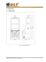
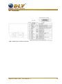
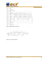
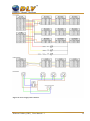
Diamond Cabinet
DWS ( type )
User’s Manual
Revision 1.1
1 Table of Contents
1.1 Sections
1
2
3
4
5
6
7
8
Table of Contents ....................................................................................................................2
1.1
Sections............................................................................................................................ 2
1.2
List of Figures ..................................................................................................................3
1.3
List of Tables ...................................................................................................................4
Revision History ......................................................................................................................5
Overview .................................................................................................................................6
3.1
Dimensions ......................................................................................................................6
3.2
Operating Elements .........................................................................................................7
3.3
Description of components .............................................................................................. 8
Installation ............................................................................................................................... 9
4.1
Installation instructions ...................................................................................................9
4.2
Power up ..........................................................................................................................9
4.3
Safety precautions............................................................................................................9
4.3.1
Static sensitive parts .............................................................................................. 10
4.3.2
Power off ...............................................................................................................10
4.3.3
Cabinet ventilation.................................................................................................10
4.3.4
Liquid ....................................................................................................................10
4.3.5
Avoid damages to the wires ..................................................................................10
4.3.6
Uncommon behavior ............................................................................................. 10
4.3.7
Wires......................................................................................................................10
4.3.8
Environment ..........................................................................................................10
Power supply .........................................................................................................................11
5.1
Position in machine .......................................................................................................11
5.2
Removal .........................................................................................................................11
5.3
Characteristics ...............................................................................................................12
5.4
Connectors .....................................................................................................................12
5.4.1
DC Output Connector ............................................................................................ 12
Coin Acceptor ........................................................................................................................13
6.1
Function .........................................................................................................................13
6.2
Accepted coins ...............................................................................................................13
6.3
Error Handling ...............................................................................................................13
6.4
Replacement ..................................................................................................................13
6.5
Connector ......................................................................................................................14
Coin Hopper .......................................................................................................................... 15
7.1
Function .........................................................................................................................15
7.2
Payout coins ...................................................................................................................15
7.3
Error Handling ...............................................................................................................15
7.4
Replacement ..................................................................................................................15
7.5
Connector ......................................................................................................................16
Bill Acceptor .........................................................................................................................17
8.1
Function .........................................................................................................................17
8.2
Accepted bills ................................................................................................................17
8.3
Adjustment and troubleshooting....................................................................................17
8.4
Error handling ................................................................................................................17
Diamond Cabinet_DWS_ Users Manual 1.1
2
8.4.1
Cleaning .................................................................................................................17
8.4.2
Bill is jammed in Acceptor ....................................................................................18
8.4.3
Bill is jammed near the acceptor's entrance .......................................................... 19
8.5
Connector ......................................................................................................................20
9 Hardware meters ....................................................................................................................21
9.1
Position in machine .......................................................................................................21
9.2
Function .........................................................................................................................21
9.3
Troubleshooting .............................................................................................................22
9.4
Exchange of the meters..................................................................................................22
10
Monitors ............................................................................................................................ 23
10.1 Position in machine .......................................................................................................23
10.2 Function .........................................................................................................................24
10.3 Troubleshooting .............................................................................................................24
10.4 Exchange of the monitors .............................................................................................. 24
11
Harness .............................................................................................................................. 25
1.2 List of Figures
Figure 1: Machine dimensions ........................................................................................................6
Figure 2: Machine Operating Elements ...........................................................................................7
Figure 3: Description of components .............................................................................................. 8
Figure 4: Machine mounting holes and dimensions ........................................................................9
Figure 5: DC Output Connector ....................................................................................................12
Figure 6: Coin Acceptor bracket position .....................................................................................14
Figure 7: Removal of the coin acceptor.........................................................................................14
Figure 8: Coin Acceptor Connector .............................................................................................. 14
Figure 9: Coin Tray Remove Direction .........................................................................................15
Figure 10: Coin Hopper Remove Direction ..................................................................................16
Figure 11: Coin Hopper Connector ............................................................................................... 16
Figure 12: Bill Acceptor Cleaning.................................................................................................18
Figure 13: Removing jammed bill from the Bill Acceptor Stacker ..............................................19
Figure 14: Removing jammed bill from the Bill Acceptor entrance .............................................19
Figure 15: Hardware Meters Position in Machine.........................................................................21
Figure 16: Exchange on the Hardware Meters Circuit Board .......................................................22
Figure 17: Monitors Position in Machine ......................................................................................23
Figure 18: Monitors Exchange ......................................................................................................24
Figure 19: Audio Connector ..........................................................................................................25
Figure 20: JCM UBA10 Connector ............................................................................................... 25
Figure 21: Buttons and Lamps Connector 1 ..................................................................................25
Figure 22: Buttons and Lamps Connector 2 .................................................................................26
Figure 23: Coin Acceptor Connector ............................................................................................ 26
Figure 24: Coin Hopper Connector ............................................................................................... 27
Figure 25: iButton Connector ........................................................................................................27
Figure 26: Key and Door Switch Connector .................................................................................27
Figure 27: Hardware Meters Connector ........................................................................................28
Figure 28: Tower Light Connector ................................................................................................ 28
Figure 29: Power Supply Unit Connector .....................................................................................29
Diamond Cabinet_DWS_ Users Manual 1.1
3
1.3 List of Tables
Table 1: DC Output Connector Pin Layout ...................................................................................12
Table 2: Accepted coin table .........................................................................................................13
Table 3: Coin Acceptor Connector Pin Layout .............................................................................14
Table 4: Payout coin table .............................................................................................................15
Table 5: Coin Hopper Connector Pin Layout ................................................................................16
Table 6: Accepted bill table ...........................................................................................................17
Table 7: Bill Acceptor Connector Pin Layout ...............................................................................20
Diamond Cabinet_DWS_ Users Manual 1.1
4
2 Revision History
Version
1.0
1.1
Date
2011.27.07
2011.17.11
Author
DLV
DLV
Diamond Cabinet_DWS_ Users Manual 1.1
Description
Initial document release
Change power supply
5
3 Overview
3.1 Dimensions
Figure 1: Machine dimensions
Diamond Cabinet_DWS_ Users Manual 1.1
6
3.2 Operating Elements
1.
2.
3.
4.
5.
6.
Coin entry
Bill entry
Belly door lock
Main door lock
I-Button key (optional)
Coin tray
1
2
3
4
5
4
6
Figure 2: Machine Operating Elements
Diamond Cabinet_DWS_ Users Manual 1.1
7
3.3 Description of components
1.
2.
3.
4.
5.
6.
7.
8.
9.
Top light
Monitors
Games PCB
Power Supply Unit
Power Supply Main
Bill Acceptor
Hopper
Coin Acceptor
Loudspeaker
1
2
2
5
3
9
9
5
9
2
4
8
5
5
9
9
6
7
Figure 3: Description of components
Diamond Cabinet_DWS_ Users Manual 1.1
8
4 Installation
4.1 Installation instructions
It must be ensured that the machine is operated in an upright position.
Further, the machine has to be screwed down tightly to the base by means on the mounting
material included in the delivery. The minimum distance between two machines should be 25
cm to avoid possible damage when opening the main door. The minimum distance to a possible
back wall or the like should be 10 cm. The mounting holes (figure 3) has to be used in case the
machine is to be installed on the table provided by the customer (machine has been delivered
without base).
Figure 4: Machine mounting holes and dimensions
4.2 Power up
Before start check the line voltage and grounding. Machine is designed to operate at 100120V/200-240V, 50-60Hz.
AC power outlet to which machine is connected should be easily accessed in case of emergency.
4.3 Safety precautions
This section is provided to avoid damage to the machine and minimize damage and chances of
electric shock to maintenance personnel and users.
Diamond Cabinet_DWS_ Users Manual 1.1
9
4.3.1 Static sensitive parts
Machine contains static-sensitive components, which could be damaged by electric discharges.
Before maintaining inner components of the machine always touch ground straps inside the
machine to neutralize electric charges.
4.3.2 Power off
In case of emergency power off the machine!
The machine will be completely powered off only when the AC plug is removed from the outlet.
If the machine is connected with the uninterruptible power supply, be sure to switch it off.
WARNING: Unplugging the machine with wet hands or in wet environment can result in
electric shock.
4.3.3 Cabinet ventilation
Do not block or insert any objects into the ventilation holes. This may result in machine
overheating or could result in risk of fire or electric shock.
Provide adequate space between machine and other objects, to allow normal ventilation
conditions.
4.3.4 Liquid
Avoid spilling any kind of liquids on the machine. Never don’t clean the machine with the water
jet. This may result in risk of fire or electric shock. In case of the accident, unplug the machine
immediately and contact the qualified technical stuff.
4.3.5 Avoid damages to the wires
Damaged power cord can result in a risk of fire or short circuit. If the power cord is damaged, it
must be replaced by a special cord available from the manufacturer or its service agent.
4.3.6 Uncommon behavior
If there are unusual sounds, lights or smells coming out of the machine, power off the machine
completely and contact the qualified technical stuff. Failure of doing so may result in risk of fire.
4.3.7 Wires
Make sure that all the wires inside and outside of the machine are not damaged, squeezed or
stretched. Also check the wire near the AC plug is not frayed.
Damaged wires can cause short circuit or fire risks.
4.3.8 Environment
Machine is suitable for indoor use only!
Do not expose the machine under any circumstances to wet environments or temperatures greater
than 50°C.
After transportation or storage in cold environments do not power up machine immediately, wait
for machine to reach normal operating temperature.
The recommended operating temperature is between 10°C and 35°C and relative humidity of
30% to 80% (non-condensing).
Do not install machine near heaters or other electronic devices that produce a lot of heat or dust.
Failure of doing so can result in risk of machine malfunction, overheating or fire.
Diamond Cabinet_DWS_ Users Manual 1.1
10
5 Power supply
5.1 Position in machine
The power supply is located under the Power distributor box (as shown on picture).
5.2 Removal
To remove the power supply, disconnect all the wiring and unscrew four screws that hold the
power supply in place (shown with red arrows).
Diamond Cabinet_DWS_ Users Manual 1.1
11
5.3 Characteristics
Type
Model
Input
Output
Output
Output
Output watt
Hsuan-I International
PR-3863-00
100-240V~ , 47Hz-63Hz
+5V:6A
+12V:20.5A
+24V:4.7A
386 W
5.4 Connectors
5.4.1 DC Output Connector
Figure 5: DC Output Connector
Pin No.
4, 8, 12
5, 9
7, 11
2, 3, 6, 10
Color
RED
YELLOW
GREEN
BLACK
Description
+5V
+12V
+24V
GND
Table 1: DC Output Connector Pin Layout
Diamond Cabinet_DWS_ Users Manual 1.1
12
6 Coin Acceptor
6.1 Function
Type
NRI G-13 ( parallel or CCTalk mode ) or compatible coin
acceptor with up to 6 pre-programmed coin channels
The coin diverter is mounted underneath the coin acceptor and sorts the coins depending on the
hopper fill level either to the hopper or directly to the cash box.
6.2 Accepted coins
Machine can accept following coins:
Country
Latvia
Coin value
1 LVL
Table 2: Accepted coin table
6.3 Error Handling
1.
2.
3.
4.
Unplug the machine and open the main door;
Check that the coin acceptor is positioned correctly, remove any jammed coins;
Ensure that the coin acceptor cable is connected properly to the device;
Check if coin sorter can freely move for one position to another.
6.4 Replacement
If coin acceptor can not be fixed in-place, the complete device should be replaced.
1.
2.
3.
4.
5.
Unplug the machine and open the main door;
Loosen black plastic brackets;
Tilt the upper part of coin acceptor first, and then remove coin acceptor from the bracket;
Unplug the cable;
Repeat steps above in the reverse order;
Diamond Cabinet_DWS_ Users Manual 1.1
13
Figure 6: Coin Acceptor bracket position
Figure 7: Removal of the coin acceptor
6.5 Connector
Figure 8: Coin Acceptor Connector
Pin No.
1
2
3
4
5
6
7
8
9
10
Description
GND
+12V DC
Coin E
Coin F
Return
Common inhibit
Coin A
Coin B
Coin C
Coin D
Potential
Low
High
Active low
Active low
Active low
Active high
Active low
Active low
Active low
Active low
Table 3: Coin Acceptor Connector Pin Layout
Diamond Cabinet_DWS_ Users Manual 1.1
14
7 Coin Hopper
7.1 Function
Type
Alberici HopperKID ( Standart or CCTalk mode ) or
compatible hopper
WARNING: Machine should be powered off before removing or installing coin hopper!
7.2 Payout coins
Machine can pay out following coins:
Country
Latvia
Coin value
1 LVL
Table 4: Payout coin table
7.3 Error Handling
1.
2.
3.
4.
Check the correct mounting of the hopper;
Check the plug fitting;
Remove jammed coins if such exist
Clean the hopper from dirt and dust
7.4 Replacement
1. Unplug the machine and open the door forvard
2. Lift the coin tray and take it out
3. Remove the Hopper forward.
Figure 9: Coin Tray Remove Direction
Diamond Cabinet_DWS_ Users Manual 1.1
15
Figure 10: Coin Hopper Remove Direction
7.5 Connector
Figure 11: Coin Hopper Connector
Pin No.
1
2
3
4
5
6
7
8
9
10
11
12
Description
Motor supply 0 volt
Logic 0 volt
uP Sensor Output
IN1
Security output
High level sense output
Low level sense output
IN2
Motor supply +24V
Logic supply
Raw Sensor Output
IN3
Table 5: Coin Hopper Connector Pin Layout
Diamond Cabinet_DWS_ Users Manual 1.1
16
8 Bill Acceptor
8.1 Function
Type
JCM UBA/Cash Code / MEI Cashflow
The Bill validator accepts the bank notes in all 4 directions. By changing software in flash
memory any country settings can be adjusted.
8.2 Accepted bills
Machine can accept and handle following banknotes
Country
Latvia
Bill value
5 LVL
10 LVL
20 LVL
50 LVL
100 LVL
Table 6: Accepted bill table
8.3 Adjustment and troubleshooting
Check +12V with Voltmeter at the output of the power supply unit.
In case of a short circuit in the machine the power supply switches off automatically.
Switch machine back on after repair of the short circuit. In most cases the power supply unit
work properly again (yellow lit).
8.4 Error handling
8.4.1 Cleaning
To clean the lenses, use a lint-free cloth and mild nonabrasive detergent such as liquid dish soap
mixed with water.
1. Pull the tabs on both sides of the acceptor forwarded to open the acceptor's head;
2. Open the acceptor head front and rear covers to clean bill path, rollers and belts.
Diamond Cabinet_DWS_ Users Manual 1.1
17
Figure 12: Bill Acceptor Cleaning
8.4.2 Bill is jammed in Acceptor
When a bill is jammed near the entrance of the stacker box, unlock the box and pull it out to
remove the jammed bill.
Diamond Cabinet_DWS_ Users Manual 1.1
18
Figure 13: Removing jammed bill from the Bill Acceptor Stacker
8.4.3 Bill is jammed near the acceptor's entrance
When a bill is jammed near the acceptor's entrance, pull the tabs on the top of the acceptor to
open the cover of acceptor’s unit. Remove the jammed bill.
Figure 14: Removing jammed bill from the Bill Acceptor entrance
Diamond Cabinet_DWS_ Users Manual 1.1
19
8.5 Connector
Table 7: Bill Acceptor Connector Pin Layout
Diamond Cabinet_DWS_ Users Manual 1.1
20
9 Hardware meters
9.1 Position in machine
Hardware meters are mounted on the right wall inside the cabinet next to gaming board.
Figure 15: Hardware Meters Position in Machine
9.2 Function
1.
2.
3.
4.
5.
6.
CREDITS WAGERED
CREDITS WON
GAMES PLAYED
BILL IN
COIN DROP
HANDPAY
Diamond Cabinet_DWS_ Users Manual 1.1
21
9.3 Troubleshooting
1. Check the connectors of the meter unit.
2. If an error message is triggered by a malfunction or non-activation of individual meter,
the device must be removed from the operation and the meters circuit board must be
exchanged.
9.4 Exchange of the meters
If any defects cannot be repaired, the defective meter has to be exchanged.
1. Unplug the machine and open the main door;
2. Unscrew screws as shown on picture;
3. Remove meters circuit board;
4. Unplug cable from the meters circuit board;
Figure 16: Exchange on the Hardware Meters Circuit Board
Diamond Cabinet_DWS_ Users Manual 1.1
22
10 Monitors
10.1 Position in machine
Figure 17: Monitors Position in Machine
Diamond Cabinet_DWS_ Users Manual 1.1
23
10.2 Function
The monitors show the game play, the error messages and the audit system.
10.3 Troubleshooting
Check if the monitors and the connectors of the cables are fixed correctly in their mounting.
10.4 Exchange of the monitors
If any defects cannot be repaired, the defective monitor has to be exchanged.
Figure 18: Monitors Exchange
Diamond Cabinet_DWS_ Users Manual 1.1
24
11 Harness
Figure 19: Audio Connector
Figure 20: JCM UBA10 Connector
Figure 21: Buttons and Lamps Connector 1
Diamond Cabinet_DWS_ Users Manual 1.1
25
Figure 22: Buttons and Lamps Connector 2
Figure 23: Coin Acceptor Connector
Diamond Cabinet_DWS_ Users Manual 1.1
26
Figure 24: Coin Hopper Connector
Figure 25: iButton Connector
Figure 26: Key and Door Switch Connector
Diamond Cabinet_DWS_ Users Manual 1.1
27
Figure 27: Hardware Meters Connector
Figure 28: Tower Light Connector
Diamond Cabinet_DWS_ Users Manual 1.1
28
Figure 29: Power Supply Unit Connector
Diamond Cabinet_DWS_ Users Manual 1.1
29