1
Series 10-800
Instruction Manual
Six and Two Stage Viable Samplers
Part Number 100072-00
29Oct2009
© 2007 Thermo Fisher Scientific Inc. All rights reserved.
Specifications, terms and pricing are subject to change. Not all products are available in all countries. Please
consult your local sales representative for details.
Thermo Fisher Scientific
Air Quality Instruments
27 Forge Parkway
Franklin, MA 02038
1-508-520-0430
www.thermo.com/aqi
WEEE Compliance
This product is required to comply with the European Union’s Waste
Electrical & Electronic Equipment (WEEE) Directive 2002/96/EC. It is
marked with the following symbol:
Thermo Fisher Scientific has contracted with one or more
recycling/disposal companies in each EU Member State, and this product
should be disposed of or recycled through them. Further information on
Thermo Fisher Scientific’s compliance with these Directives, the recyclers in
your country, and information on Thermo Fisher Scientific products which
may assist the detection of substances subject to the RoHS Directive are
available at: www.thermo.com/WEEERoHS.
Thermo Fisher Scientific
WEEE Compliance
Warranty
Seller warrants that the Products will operate or perform substantially in
conformance with Seller's published specifications and be free from defects in
material and workmanship, when subjected to normal, proper and intended
usage by properly trained personnel, for the period of time set forth in the
product documentation, published specifications or package inserts. If a
period of time is not specified in Seller’s product documentation, published
specifications or package inserts, the warranty period shall be one (1) year
from the date of shipment to Buyer for equipment and ninety (90) days for
all other products (the "Warranty Period"). Seller agrees during the Warranty
Period, to repair or replace, at Seller's option, defective Products so as to
cause the same to operate in substantial conformance with said published
specifications; provided that (a) Buyer shall promptly notify Seller in writing
upon the discovery of any defect, which notice shall include the product
model and serial number (if applicable) and details of the warranty claim; (b)
after Seller’s review, Seller will provide Buyer with service data and/or a
Return Material Authorization (“RMA”), which may include biohazard
decontamination procedures and other product-specific handling
instructions; and (c) then, if applicable, Buyer may return the defective
Products to Seller with all costs prepaid by Buyer. Replacement parts may be
new or refurbished, at the election of Seller. All replaced parts shall become
the property of Seller. Shipment to Buyer of repaired or replacement
Products shall be made in accordance with the Delivery provisions of the
Seller’s Terms and Conditions of Sale. Consumables, including but not
limited to lamps, fuses, batteries, bulbs and other such expendable items, are
expressly excluded from the warranty under this warranty.
Notwithstanding the foregoing, Products supplied by Seller that are
obtained by Seller from an original manufacturer or third party supplier are
not warranted by Seller, but Seller agrees to assign to Buyer any warranty
rights in such Product that Seller may have from the original manufacturer
or third party supplier, to the extent such assignment is allowed by such
original manufacturer or third party supplier.
In no event shall Seller have any obligation to make repairs, replacements or
corrections required, in whole or in part, as the result of (i) normal wear and
tear, (ii) accident, disaster or event of force majeure, (iii) misuse, fault or
negligence of or by Buyer, (iv) use of the Products in a manner for which they
were not designed, (v) causes external to the Products such as, but not
limited to, power failure or electrical power surges, (vi) improper storage and
handling of the Products or (vii) use of the Products in combination with
equipment or software not supplied by Seller. If Seller determines that
Products for which Buyer has requested warranty services are not
Warranty
Thermo Fisher Scientific
covered by the warranty hereunder, Buyer shall pay or reimburse Seller for
all costs of investigating and responding to such request at Seller's then
prevailing time and materials rates. If Seller provides repair services or
replacement parts that are not covered by the warranty provided in this
warranty, Buyer shall pay Seller therefor at Seller's then prevailing time and
materials rates. ANY INSTALLATION, MAINTENANCE, REPAIR,
SERVICE, RELOCATION OR ALTERATION TO OR OF, OR
OTHER TAMPERING WITH, THE PRODUCTS PERFORMED BY
ANY PERSON OR ENTITY OTHER THAN SELLER WITHOUT
SELLER'S PRIOR WRITTEN APPROVAL, OR ANY USE OF
REPLACEMENT PARTS NOT SUPPLIED BY SELLER, SHALL
IMMEDIATELY VOID AND CANCEL ALL WARRANTIES WITH
RESPECT TO THE AFFECTED PRODUCTS.
THE OBLIGATIONS CREATED BY THIS WARRANTY
STATEMENT TO REPAIR OR REPLACE A DEFECTIVE PRODUCT
SHALL BE THE SOLE REMEDY OF BUYER IN THE EVENT OF A
DEFECTIVE PRODUCT. EXCEPT AS EXPRESSLY PROVIDED IN
THIS WARRANTY STATEMENT, SELLER DISCLAIMS ALL OTHER
WARRANTIES, WHETHER EXPRESS OR IMPLIED, ORAL OR
WRITTEN, WITH RESPECT TO THE PRODUCTS, INCLUDING
WITHOUT LIMITATION ALL IMPLIED WARRANTIES OF
MERCHANTABILITY OR FITNESS FOR ANY PARTICULAR
PURPOSE. SELLER DOES NOT WARRANT THAT THE PRODUCTS
ARE ERROR-FREE OR WILL ACCOMPLISH ANY PARTICULAR
RESULT.
Thermo Fisher Scientific
Warranty
TABLE OF CONTENTS
SECTION
I.
II.
III.
IV.
TITLE
PAGE NO.
PREFACE
1
INTRODUCTION
2
AERODYNAMIC PARTICLE SIZING
7
IMPACTORS
10
A.
10
SIX-STAGE VIABLE PARTICLE SAMPLER
1.
DESCRIPTION
10
2.
ASSEMBLY
12
3.
SAMPLING
13
4.
CALIBRATION
14
B. TWO-STAGE ALUMINUM VIABLE
PARTICLE SAMPLER
V.
VI.
16
1.
DESCRIPTION
16
2.
ASSEMBLY
17
3.
SAMPLING
17
4.
CALIBRATION
18
ANALYSIS AND INTERPRETATION OF DATA
20
INSTRUCTIONS FOR THE VACUUM PUMP
25
LIST OF TABLES
TABLE
TITLE
PAGE NO.
1
POSITIVE HOLE CONVERSION TABLE (400)
23
2
POSITIVE HOLE CONVERSION TABLE (200)
24
LIST OF FIGURES
FIGURE
TITLE
PAGE
NO.
1
SAMPLER STIMULATES
HUMAN RESPIRATORY SYSTEM
8
2
SIX-STAGE VIABLE SAMPLER
11
-1-
I . PREFACE
The assay of the microbial content of the air has become increasingly more
significant in the past d e c a d e as the need for “contamination-free”
environments has become more apparent. The treatment of hospital patients,
medical as well as surgical, who are high risk candidates for infection; the
manufacture and processing of sterile materials and pharmaceuticals, and the
increased use of these products; the massive production and wide
distribution of convenience foods; and the growing emphasis on consumer
protection have all contributed to the need for controlled environments.
Biological aerosols have been defined as viable biological contaminants
occurring as solid or liquid particles in the air. These particles can vary
in size from viruses less than 0.1 micron in diameter to fungal spores 100 or
more microns in diameter. They may occur as single, unattached organisms or
as aggregates.
Viable particle samplers have been generally used to collect and assay
aerobic species of bacteria and fungi. Even though many viable samplers,
including the Thermo Fisher Scientific Andersen Viable Cascade Impactor
(ACI), will collect some virus particles, there is no convenient, practical
method for the cultivation and enumeration of these particles. There are two
constraints on all viable particle samplers for which there is no analog in
the assay of nonbiological aerosols. First, the particle must be separated
from the air for any viability assay, and second, the ability to reproduce
(viability) must be demonstrated.
The purpose of this manual is to outline proper methods for the assay of
biological aerosols using the Andersen Viable Cascade Impactor (ACI).
-2-
I I . INTRODUCTION
SIX-STAGE VIABLE CASCADE IMPACTOR
The Six-Stage ACI is a multi-orifice, cascade impactor which is normally
used to measure the concentration and particle size distribution of
aerobic bacteria and fungi in the intramural or ambient air. This
instrument has been widely used as a standard for enumerating the viable
particles in a microbial aerosol. Viable particles can be collected on a
variety of bacteriological agar and incubated in situ for colony
counting and identification.
This sampler was calibrated so that all particles collected, regardless of
physical size, shape, or density are sized aerodynamically and can be
directly related to human lung deposition.
TWO-STAGE ALUMINUM VIABLE CASCADE IMPACTOR
The Two-Stage ACI is also a multi orifice cascade impactor. This unit is
used whenever a size distribution is not required and only respirablenonrespirable segregation or total counts are needed: Ninety-five to one
hundred percent of the viable particles above 0.8 microns in an aerosol
can be collected on a variety of bacteriological agar.
This impactor separates viable particles into two size ranges with
the 50% cut-off diameter of Stage 1 at 8.0 microns for spherical
particles of unit density. The impactor is fabricated of aluminum
and is reusable.
-3-
A brief description of the operation of the viable particle samplers
follows:
1. Six-Stage Viable Particle Sampler
a. Collection plates are prepared by aseptically pipetting 27m1
of sterile bacteriological agar (45-50°C) into each of six
glass Petri dishes supplied with the instrument. The Petri
dishes must be sterilized prior to filling. Petri dishes,
other than those supplied, cannot be used since this would alter
the distance between the jet orifice and the collection surface
of each stage. Plastic Petri dishes should not be used because
the static charge generated reduces the collection efficiency.
b.
Any general purpose, solid bacteriological medium, such as
trypticase soy agar or blood agar, can be used for the collection
plates. Selective media are not recommended since they inhibit
the repair and growth of injured or stressed cells.
c.
One collection-plate, with the cover removed, is inserted
on each stage of the sampling instrument.
d.
The air to be sampled enters the inlet cone and cascades
through the succeeding orifice stages with successively higher
orifice velocities from Stage 1 to Stage 6. Successively
smaller particles are inertially impacted onto the agar
collection surfaces.
-4-
e.
Viable particles are retained on the agar plates, and the
exhaust air is carried-through the vacuum hose to the vacuum
source (pump or in-house vacuum system).
f.
For maximum collection efficiency, a constant air sampler flow
of 1 ACFM must be provided. This constant flow is provided with
a continuous-duty, carbon vane vacuum pump, and is controlled
by an adjustable valve on the pump. Periodic calibration is
recommended (See Section VI). Another method of assuring a
constant flow would be to insert an airflow meter (not provided),
with a minimum capacity of 1 ACFM (28.3 liters/min.) in the
vacuum hose between the Sampler and the vacuum source. This
flowmeter should be properly calibrated.
g.
After sampling is completed, the sampling time is recorded, the
agar collection plates are removed from the sampling instrument,
and the cover is replaced on each Petri dish. Identify each
plate as to sample and stage number (i.e., 1-1, 1-2, 1-3, etc.).
h.
Place all agar plates, inverted to prevent condensation drip,
in an incubator at 35°C for 18 to 24 hours. Plates can be
incubated at room temperature if the user is most interested in
environmental bacteria whose optimum growth temperature is lower
than body temperature or at 20° to 25°C for maximum recovery of
fungi.
i.
After incubation, the number of colonies on each plate are
counted, using a standard bacterial colony counter.
j.
Knowing the air sample flow rate and the sampling time, the
mean number of viable particles (aerobic bacteria and/or fungi)
per unit volume of air can be calculated, and the percent of
particles in each size range can be estimated.
-52. Two-Stage Viable Particle.Samplers
a. Collection plates are prepared by aseptically pipetting 20ml of
sterile bacteriological agar (45-50°C) into each of two sterile
100xl5mm plastic, disposable Petri dishes. An anti-static chemical
has been incorporated into the plastic used to fabricate the
disposable sampler. Commercially available agar plates (20 ml agar)
can be substituted for user-prepared collection plates.
b.
Any general purpose, solid bacteriological medium, such as
trypticase soy agar, or blood agar, can be used for the collection
plates. Selective media are not recommended since they inhibit the
repair and growth of injured or stressed cells.
c.
One collection plate, with the cover removed, is inserted on
each stage of the sampling instrument.
d.
The air to be sampled enters the jet orifices of Stage I and
cascades through the jet orifices of Stage II with a higher
orifice velocity through Stage II than Stage I. Smaller
particles are inertially impacted on the agar plate in Stage II
than in Stage I.
e.
Viable particles are retained on the agar plates, and the
exhaust air is carried through the outlet in the base of the
instrument, and the vacuum hose to the vacuum source (pump or inhouse vacuum system).
f.
For maximum collection efficiency, a constant air sample flow of 1
ACFM must be provided.
-6-
g.
After sampling is completed, the sampling time is
recorded, the agar collection plates are removed from the
sampling instrument and the cover is replaced on each
Petri dish. Identify each plate as to sample and stage
number (i.e., 1-1, 1-2).
h.
Place both agar plates, inverted to prevent
condensation drip, in an incubator at 35°C for 18 to 24
hours. Plates can be incubated at room temperature if the
user is most interested in environmental bacteria whose
optimum growth temperature is lower than body temperature
or at 20-25°C for maximum recovery of fungi.
i.
After incubation, the number of colonies on each plate
are counted using a standard bacterial colony counter.
j.
Knowing the air sample flow rate and the sampling time, the
mean number of viable particles (aerobic bacteria and/or
fungi) per unit volume of air can be calculated and the
percent of particles in the respirable (Stage II) and
nonrespirable (Stage I) size ranges can be estimated.
-7-
III. AERODYNAMIC PARTICLE SIZING
The design concept of the ACI evolved from the following
information:
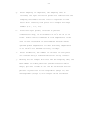
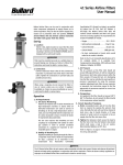
The human respiratory tract is an aerodynamic classifying system for
airborne particles. A sampling device can be used as a substitute for
the respiratory tract as a collector of viable airborne particles and
as such, it should reproduce to a reasonable degree the lung
penetration by these particles. The fraction of inhaled particles,
retained in the respiratory system and the site of deposition vary with
all the physical properties (size, shape, density) of the particles
which make up the aerodynamic dimensions (Figure 1). Because the lung
penetrability of unit density particles is known and since the particle
sizes that are collected on each stage of the ACI have been determined,
if a standard model of these samplers is used according to standard
operating procedure, the stage distribution of the collected material
will indicate the extent to which the sample would have penetrated the
respiratory system.
Numerous small round jets improve collection (impaction) efficiency and
provide a sharper cutoff of particle sizes on each stage of inertial
impactors. Thus, the Six-Stage ACI with 400 small round jets per stage
and the Two-Stage ACI with 200 tapered round jets per stage meet all
the criteria for the efficient collection of airborne viable particles.
Recent reports have discussed a reduced efficiency in cascade impactors
when particles bounce off the impaction surface, are reintrained and
lost in the exhaust air. This effect is minimized when a sticky agar
surface is used as the collection medium.
-8-
Figure 1. Six-Stage ACI Sampler Simulates Human Respiratory System
The earliest and most fundamental work in inertial impaction theory
was conducted in the early 1950's by Ranz and Wong. In this work,
Ranz and Wong showed that the collection of a particle by an obstacle
is a function of what is defined as the inertial impaction parameter:
K= CpUDp2
18μDc
Where U is the relative velocity, p is the particle density, Dp is the
particle diameter, μ is the gas viscosity, Dc is the diameter of the
round jet, and C is the Cunningham slip correction factor.
Data from inertial impactors are normally presented as 50% effective
cutoff
diameters.
For
the
ACI,
containing
round
jets
and
flat
collection surfaces, the 50% effective cutoff diameter would yield a
value of 0.14 for the inertial impaction parameter K.
-9-
The Cunningham slip correction factor is equal to:
C = 1 + 0.16 x 10⁻⁴/Dp for normal temperatures and pressures. This
factor corrects for the fact that as particle diameters approach the mean
free path length of the gas molecules, they tend to "slip" between gas
molecules more easily and are therefore more easily able to cross the bulk
flow stream lines. The collection efficiency is therefore slightly greater
than would be predicted by inertial impaction theory for particle diameters
on the order of 1 or 2 microns. The overlapping of particle size between
stages, which is naturally inherent in all cascade impaction devices, is
minimized in these samplers by design. Ranz and Wong (1952) stated that as
a particle passes through a jet, its nearness to the axis of the jet is one
of the factors that determines whether or not the particle will reach the
impaction surface. In contrast to competitive samplers which have larger
rectangular jets in each stage, the ACI sampler has 400 small, round jets.
Travel of the particle is thus confined near the axis of the jets. The
average distance of the particles from the axis. of the jets is less than
in other impactors. Ranz and Wong (1952) also stated that round jets have
sharper cutoffs than rectangular jets. The ACI sampler, therefore, on a
theoretical basis, should have a sharper cutoff.
Another inherent advantage of the ACI over its competitors is that
single circular orifice and multiple rectangular orifice impactors by
design must operate with higher orifice velocities. This results in more
turbulent flow, greater re-entrainment, and a skewing of the size
distribution toward the lower end {i.e., the indicated size distribution
being smaller than it really is).
-10IV I M P A C T O R S
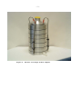
A. SIX-STAGE VIABLE CASCADE IMPACTOR
1. Description
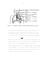
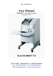
The Six-Stage ACI is constructed with six aluminum stages that are
held together by three spring clamps and sealed with O-ring gaskets
(Figure 2). Each impactor stage contains multiple precision drilled
orifices. When air is drawn through the sampler, multiple jets of
air in each stage direct any airborne particles toward the surface of
the agar collection surface for that stage. The size of the jet
orifices is constant within each stage, but are smaller in each
succeeding stage. The range of particle sizes collected on each stage
depends on the jet velocity of the stage and the cutoff of the
previous stage. Any particle not collected on the first stage follows
the air stream around the edge of the Petri dish to the next stage.
Each stage contains 400 orifices with diameters ranging from 1.81 mm on the
first stage to 0.25 mm on the sixth stage. Each stage has a removable glass
Petri dish with metal cover. The exhaust section of each stage is
approximately 19 mm larger in diameter than the Petri dish which allows
unimpacted particles to go around the dish and into the next stage (Figure
3).
The ACI and Vacuum pump include their own carrying cases for ease of
portability (Figure 4).
Case dimensions are 9 3/8" wide x 8 3/4" high x 5” deep. Complete sampler and
vacuum pump weights including carrying cases are 6 ¼ pounds and 12 pounds
respectively. A constant air sample flow of 1 ACFM is provided by a continuous
duty vacuum pump. Flow rate is controlled by an adjustable valve on the pump
and periodic calibration is recommended. Requirements for flow rate adjustments
can be found in Section VI.
-11-
Figure 2. TFS ACI Six-Stage Viable Sampler
-122. Assembly
The orifice stages should be cleaned and disinfected each time the
instrument is used. A mild pH neutral detergent and warm water are
sufficient for cleaning. The soap can be removed by holding the stages
under hot running water or immersing them in clean water in an
ultrasonic cleaner. Each stage should be examined for any material in
the jet holes. If holes are plugged, or partially plugged, a jet blast
of dry air is effective in cleaning them. Just before use, wipe all
surfaces with 70% isopropyl alcohol using a lint free gauze pad.
The complete impactor assembly consists of an inlet cone, six stages,
and 12 glass petri dishes (includes 6 spare dishes). The stages are
inscribed 1, 2, 3, 4, 5 and 6. Each stage contains an O-ring for
sealing. These O-rings should be checked regularly and replaced when
they no longer provide an airtight seal.
The assembly of the Six-Stage ACI begins by placing an agar collection
plate, uncovered, on the base plate so that the Petri dish rest on
three raised metal pins. Insert Stage 6 over the Petri dish. Place a
second Petri dish on the top of Stage 6 and continue this manner until
all six agar collection plates have been positioned in the ACI. The
inlet cone is placed on top of Stage 1. All the agar plates should be
at room temperature before they are inserted into the sampling
instrument.
When the Petri dishes supplied with the sampler are used and 27ml of
agar medium is placed in each Petri dish, the three metal pins on each
stage position the collection surface for the correct distance between
the jet orifices and the agar surface.
-13-
After the ACI has been assembled, connect the outlet nipple on the
base plate to the vacuum pump or other vacuum source.
3. Sampling
When ready to sample, the vacuum pump is turned on and a sample stream
of 1 ACFM will flow through the sampler. Figure 5 shows how impaction
occurs at the orifice-collector interfaces.
Normal sampling periods for viable aerosols will vary from a few
minutes up to 30 minutes depending on the purpose for which the sample
is collected and the type of air environment being sampled. It is
important to collect sufficient viable particles in each sample to be
statistically significant and representative, however, difficulty is
encountered in counting agar plates which contain more than 250-300
colonies.
The flow of high velocity sample air across the agar plates also tends
to dehydrate and perhaps damage the viable particles which have already
been collected. Thus, extended sampling periods (over 30 minutes) are
not recommended. If a larger sample volume is required, it is better to
use two sampling instruments in parallel or to remove the agar plates
representing one sample and insert fresh plates for a second sample.
-14-
Figure 5. Schematic of Impactor Stage
After the sampling has been completed, the ACI is disassembled and the
covers are replaced on each of the Petri dishes.
4. Calibration
Since the size fraction for each stage is determined by the orifice
velocities, it is important that the ACI be operated at 1 ACFM. For this
reason, the unit should be periodically recalibrated and whenever nonstandard temperatures and pressures are encountered, calibration should be
performed at the sampling conditions. Do not use rubber
-15tubing of smaller diameter or length different than that supplied with
the impactor unless the flow rate is readjusted.
Each ACI pump is equipped with an adjustable valve. Always tighten the lock
nut on the adjustment valve after the flow rate has been set. To adjust the
flow, turn the screw in to increase flow and out to decrease flow.
Each ACI pump impactor assembly is calibrated before shipment to deliver 1
ACFM at ambient temperature and pressure levels in Franklin, MA. In order to
recalibrate at your sampling environment, the following procedure is
recommended:
Place a calibrated flow meter upstream from the ACI. Attach a
short 1" I.D. hose with approximately 1/4" wall to the inlet cone
of the impactor and the other end to the outlet of the flow meter.
Adjust the pump valve until you are pulling l ACFM over a three
minute test period as determined with an accurate stop watch. After
maintaining 1 ACFM for three minutes, tighten the lock nut on the
adjustment valve.
Because of the 1.4 ACFM free flow rating of the motor and pump, up to 50 feet
of tubing can be used between the Sampler and pump while still maintaining 1
ACFM through the ACI.
The pump and motor are guaranteed by the original manufacturer and should not
be disassembled for any reason. The pump and motor require no lubrication.
The pump rate of the 12 volt DC pump will vary with voltage. One ACFM can be
drawn through the impactor if the voltage is maintained near 12 volts. Refer to
the attached supplementary titled "Instructions For 12 Volt Pump" for detailed
12 volt DC pump operation.
-16B. TWO-STAGE ALUMINUM VIABLE CASCADE IMPACTOR
1. Description
The ACI is constructed of aluminum with two stages which are held
together with three dowel pins and three Teflon caps. Each
impactor stage contains multiple precision drilled orifices. When
air is drawn through the ACI, multiple jets of air in each stage
direct any airborne particles toward the surface of the agar
collection surface for that stage. The size of the jet orifices is
the same on each of the two stages but are smaller on the second
stage. The range of particle sizes collected on each stage
depends on the jet velocity of the stage and the cutoff of the
previous stage. Any particle not collected on the first stage
follows the air stream around the edge of the Petri dish to the
second stage.
Each stage contains 200 tapered orifices. The diameter of the orifices on
the first stage are 1.5 mm and 0.4 mm on the second stage. Standard 100 x
15 mm petri dishes are used for collecting surfaces on each stage. The
exhaust section of each stage is approximately 19 mm larger in diameter
than the Petri dish which allows unimpacted particles to go around the dish
and into the next stage (Figure 3).
A continuous duty, carbon vane vacuum pump is available which will
provide a constant sample flow of 1 ACFM.
The 50% effective cutoff diameter of Stage I of this Sampler is 8.0
microns for spherical particles of unit density (or their aerodynamic
equivalent). A reasonable working interpretation would
-17conclude that non-respirable particles (do not penetrate the lower human
respiratory tract) are collected on Stage I and respirable size particles
(will penetrate the lower human respiratory tract) are collected on
Stage II.
2.
Assembly
The complete impactor assembly consists of a base, two stages, and
three threaded Teflon caps (Figure 7).
The assembly of the two-stage impactor begins by placing an agar
collection plate, uncovered, on the base so that the Petri dish rests
on the three post supports. Place Stage II carefully over the three
dowel pins and slide into position over the Petri dish. Place the
second Petri dish on the top of Stage II and carefully cover with
Stage I. Screw the three caps onto the dowel pins and tighten by hand.
Connect a vacuum hose (not supplied) to the nipple on the base of the
instrument. Connect the vacuum hose to a vacuum source.
When a 100 x 15 mm Petri dish containing 20 ml of agar medium is
correctly placed on the support posts of each stage, the correct
distance between the jet orifices and the agar surface is maintained.
3.
Sampling
When ready to sample, the vacuum source is turned on. A constant sample
flow rate of 1 ACFM (28.3 liters/min.) must be maintained. Accurately time
the length of the sampling period.
Normal sampling periods for viable aerosols will vary from a few minutes
up to 30 minutes depending on the purpose for which the sample
-18-
is collected and the type of air environment being sampled. It is
important to collect sufficient viable particles in each sample to be
statistically significant and representative. However, difficulty is
encountered in counting agar plates which contain more than 250-300
colonies.
The flow of high velocity sample air across the agar plates also tends to
dehydrate and perhaps damage the viable particles which have already been
collected. If a larger sample volume or a longer sampling time (over 30
minutes) is required, it is better to use two or more sampling
instruments in parallel or to sample sequentially.
After the sampling has been completed, the Sampler is disassembled. This is
accomplished by unscrewing the Teflon caps. Remove Stage I and the Petri
dish on Stage I and replace its cover. Remove Stage II and the Petri dish
on Stage II and replace its cover.
4. Calibration
Since the size fraction for each stage is determined by the orifice
velocities, it is important that the ACI be operated at 1 ACFM. For this
reason, the unit should be periodically recalibrated and whenever non-standard
temperatures and pressures are encountered, calibration should be performed at
the sampling conditions. Do not use rubber tubing of smaller diameter or length
different than that supplied with the impactor unless the flow rate is readjusted.
Each ACI pump is equipped with an adjustable valve. Always tighten the lock nut on
the adjustment valve after the flow rate has been set. To adjust the flow, turn the
screw in to increase flow and out to decrease flow.
-19-
Each ACI pump impactor assembly is calibrated before shipment to deliver 1
ACFM at ambient temperature and pressure levels in Franklin, MA. In order to
recalibrate at your sampling environment, the following procedure is
recommended:
Place a calibrated flow meter upstream from the ACI. Attach a
short 1" I.D. hose with approximately 1/4" wall to the inlet cone
of the impactor and the other end to the outlet of the flow meter.
Adjust the pump valve until you are pulling l ACFM over a three
minute test period as determined with an accurate stop watch. After
maintaining 1 ACFM for three minutes, tighten the lock nut on the
adjustment valve.
Because of the 1.4 ACFM free flow rating of the motor and pump, up to 50 feet
of tubing can be used between the Sampler and pump while still maintaining 1
ACFM through the ACI.
The pump and motor are guaranteed by the original manufacturer and should not
be disassembled for any reason. The pump and motor require no lubrication.
The pump rate of the 12 volt DC pump will vary with voltage. One ACFM can be
drawn through the impactor if the voltage is maintained near 12 volts. Refer to
the attached supplementary titled "Instructions For 12 Volt Pump" for detailed
12 volt DC pump operation.
-20-
V. ANALYSIS AND INTERPRETATION OF DATA
The number of viable aerobic particles per unit volume of air
sampled is easily computed. After incubation, count the number of
bacterial colonies (accepted microbiological theory assumes that
each colony represents a single particle) on each sample plate. Sum
the number of colonies on each plate to give a grand total for that
particular sample. Divide this total by the total volume of air
sampled in cubic feet (if a constant flow rate of 1 ACFM is
maintained, the volume of air sampled is equal to the number of
minutes sampled) to give the mean number of viable particles per
cubic foot of air in the sample.
Total Number of Colonies from all Sample Plates =
Total Sampling Time in Minutes (1 ACFM)
Mean Number of
Viable Particles
per Cubic Foot
of Air Sampled
Note that the number of viable particles in the air sample is not equal
to the number of bacterial cells in the sample since a single viable
particle may contain more than one cell. If the sample plates have been
incubated aerobically, all the colonies must be considered as aerobic or
facultative anaerobic bacteria.
The percentage of viable particles in each size range can be determined
by dividing the number of colonies on a given stage by the total number
of colonies on all the stages.
Colonies on Stage 1 of the Six-Stage Sampler
X 100 =
Total Number of Colonies from all Sample Plates
Percent of
Viable Particles
Over 7.0 Microns
In Diameter
The site of deposition of these particles in the human respiratory tract can
be predicted from this data. The approximate settling rate in air of the
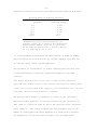
-21particles collected can also be calculated from the particle size data.
Settling Rates of Airborne Particles
Diameter of Particles
Velocity of Settling
(microns.)
(feet per minute)
0.8
1.0
4.0
10.0
40.0
100.0
0.005
0.007
0.095
0.59
9.5
59.2
Condensed from "Size and characteristics of
airborne solids", W. G. Frank in the Smithsonian
Meteorological Tables. Rates are for particles
in the shape of spheres with a specific gravity
of 1.0, settling in air at 70°F.
It is not possible to determine the exact density or shape of viable
particles which are collected with any cascade impactor including the
Six and Two Stage Viable Cascade Impactors.
The variation in concentration of viable airborne particles with time
can be determined by collecting intermittent samples at the same
location.
Agar plates containing m o r e t h a n 3 0 0 colonies may be counted by a
“positive hole” method, which is less accurate than optically counting each
colony, and is rarely used today. However, since some people still use this
technique, the following discussion is included:
The positive hole method is essentially a count of the jets which
delivered viable particles to the Petri plates and the conversion of
this count to a particle count by use of the “positive hole” conversion
table (Table I). This table is based upon the principle that as the
number of viable particles being impinged on a given plate increases,
the probability of the next particle going into an “empty hole”
-22-
decreases. For example, when 9/10 of the holes have each received one or more
particles, the next particle has but one chance in ten of going into an empty
hole. Thus, at this point, on the average, ten additional particles would be
required to increase the number of positive holes by one, and before all the
holes become positive, some holes will receive a number of particles. The
Where Pr is the expected number of viable particles to produce r positive holes
and N is the total number of holes per stage (400). The above formula assumes
that the flow of particles stops at the instant a particle enters the rth
hole. Since, in the actual case of sampling, the flow of particles stops at
random, the expected number of particles present if r positive holes are
observed, would be equal to or greater than Pr but less than Pr+1 and the
average would be (Pr+Pr+1 -1)/2. This correction has been applied in the
construction of the table.
In using the positive hole conversion table the number of positive holes must be
precisely determined. A colony out of the hole pattern is not counted as a positive
hole. By this method, counts up to 1,200 or 1,500 particles per stage are quite
reliable. If higher counts are to be encountered the microscope method is employed.
With this method, the number of viable particles per stage is determined after a
short incubation period by counting, with the aid of a microscope, the microcolonies in a number of deposit areas and calculating the total for the plate. A
deposit area is that area which receives particles from one jet or hole. The micro-
-23counted. By this method, total sampler counts as high as 40,000 or
50,000 can be made.
-24-
-25-
VI. INSTRUCTIONS FOR 12 VOLT VACUUM PUMP
Pump and motor require no lubrication.
Do not use rubber tubing of smaller diameter or length than that supplied
with the unit unless the flow rate is checked and readjusted.
The pump is equipped with an adjustable valve. Always tighten the lock nut
on the adjustment valve after the flow rate has been set.
To adjust flow - turn screw in to increase the flow and out to decrease
the flow.
It is important the unit always operate at 1 cfm. The unit should be
periodically recalibrated. To calibrate - attach a 1" (I.D.) hose with
approximately a 1/4" wall to the inlet nozzle of the sampler and the other
end to the outlet of a flow meter. Continue to adjust the valve until you
are pulling 1 cfm over a three minute test period (determined by an
accurate stop watch). After this has been achieved, tighten the lock nut on
the adjustment valve.
The pump and motor should not be disassembled for any reason.
Due to the 1.4 cfm rating of the motor and pump, up to 50 feet of hose can
be used between the sampler and the motor and still pull 1 cfm.
12 VOLT PUMP OPERATION
Battery required: 12 volt automotive type, minimum 69 amp hour capacity
TO OPERATE
1. Connect clip of red shielded pump wire to positive (+ or Red)
battery terminal.
-26-
2. Connect clip of black shielded wire to negative (-)
terminal, pump should start immediately.
3. If pump does not start, check battery voltage, should be not
less than 12 volts under light load, 13 volts no load.
4. If pump does not operate with fully charged battery, check
battery clip connections and wires for poor connections.
5. Should pump fail to operate after Steps 1-4 are completed,
refer to manufacturer's instructions attached.
6. Pumping rate of the 12V DC unit will vary with voltage. Normal
pump operation requires a current draw of approximately 11 amps.
Continuous running in excess of 3 hours may result in reduced
battery voltage and lower CFM through the ACI.
7. Fully recharge battery between uses.
SERVICE LOCATIONS
For additional assistance, worldwide service is available from Thermo Fisher
Scientific. Contact one of the phone numbers below for product support and
technical information or visit us on the web at www.thermo.com/aqi.
Toll Free U.S. only
1-866-282-0430
U.S., Latin America, and Canada
Europe
+31 76 579 5555
China
+86 10 8419 3588
Asia Pacific
+91 22 27781102
1-508-520-0430