1
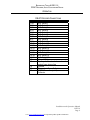
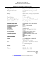
I N S TA L L AT I O N A N D O P E R AT I O N MANUAL for the Broadcast Tools® DEC-16 DTMF Decoder, Auto-Coupler and Dialer Broadcast Tools® is a registered trademark of Broadcast Tools, Inc. Copyright 1989 - 2004 by Broadcast Tools, Inc. All rights reserved. No part of this document may be reproduced or distributed without permission. ALL SPECIFICATIONS AND FEATURES FOR THIS PRODUCT ARE SUBJECT TO CHANGE WITHOUT NOTICE Firmware version 1.07 and above Manufactured with pride in the USA Manual Revised 01/16/2004 BROADCAST TOOLS ® DEC-16 DTMF DECODER, AUTO-COUPLER AND DIALER TABLE OF CONTENTS Introduction 3 Safety Information 3 Who To Contact For Help 3 FCC Notice 4 Product Description 5 Basic Hook Up Programming Security Code Programming Number of Rings Master/Slave Setting Operation DIP Switches DIP Switch Settings Table DTMF Guard Times RS-232 Interface DB-37 Decoder Connections 5 5 5 6 6 6 7 7 7 8 Specifications 9 Warranty 10 Installation and Operation Manual DEC-16 Page 2 Visit www.broadcasttools.com for important product update information. BROADCAST TOOLS ® DEC-16 DTMF DECODER, AUTO-COUPLER AND DIALER INTRODUCTION Thank you for your purchase of a Broadcast Tools® DEC-16 DTMF Decoder, AutoCoupler and Dialer, (referred to as the DEC-16 throughout this manual). We’re confident that this product will give you many years of dependable service. This manual i s intended to give you all the information needed to install and operate the Broadcast ® Tools DEC-16. NOTE: This manual should be read thoroughly before installation and operation. SAFETY INFORMATION Only qualified personnel should install Broadcast Tools® products. inappropriate use and/or installation could result in a hazardous condition. CAUTION! Incorrect or Broadcast Tools® Products, as with any electronic device, can fail without warning. Do not use this product in applications where a life threatening condition could result due to failure. WHO TO CONTACT FOR HELP If you have any questions regarding your product or you need assistance, please contact your distributor from whom you purchased this equipment. If you would like more information about Broadcast Tools® products, you may reach u s at: Broadcast Tools, Inc. 131 State Street Sedro-Woolley, WA 98284-1540 USA Voice: 360 . 854 . 9559 Fax: 360 . 854 . 9479 Internet Home Page: E-mail: www.broadcasttools.com [email protected] THANK YOU FOR CHOOSING BROADCAST TOOLS® BRAND PRODUCTS! Installation and Operation Manual DEC-16 Page 3 Visit www.broadcasttools.com for important product update information. BROADCAST TOOLS ® DEC-16 DTMF DECODER, AUTO-COUPLER AND DIALER FCC NOTICE 1. UPON REQUEST ONLY, you must provide the following data to your telephone utility company (telco): (a) Notice of intention to install or permanently remove an FCC Part 68 registered device or system, and the *FCC registration Number. (b) *The Ringer Equivalence (R.E.N.) number (see device label). Note that if several devices are connected to the same line, the R.E.N.'s must not add up to more than 5.0 {A or B}. This R.E.N. figure is important to your telco. (c) *The (USOC) jack type to be provided by the telco. Typically these will be RJ11C/W for single lines. 2. *The *-flagged items above are noted on the equipment's FCC Compliance label. 3. This device may not be used on telco-operated coin phone lines. Party lines & privately owned coin-phones are subject to local State regulatory policies, and possible additional State special requirements. 4. The telco has the right to make changes to their network which may affect the operation of your equipment, provided you are given adequate advance written notice to permit correct operation. 5. In case of operational problems, disconnect your unit by removing the modular plug from the telco's jack. If your regular phone (or other device or system) still works properly, your DEC-16 has a problem and must remain disconnected and (officially) serviced or returned for repairs. If upon the above disconnection your regular service still has problems, notify your telco that they may have a problem. Request prompt service at no cost to you the user. If a problem is found in premises wiring not telco-installed, you are subject to a service charge. If a fault is in telco-installed wiring, you may be subject to a service call charge. 6. Unless otherwise noted in the User's Manual, user may not under any circumstances (in or out of warranty) attempt any service, adjustments or repairs on this unit. It must be returned to the factory or authorized U.S. service agency for all such work. Locations and phone numbers of factory or authorized U.S. service points are listed in this user's manual. 7. Special FCC rules apply to equipment connected behind a PBX or KTS. 8. This device complies with the limits for a class B digital device, pursuant to part 15 of the FCC rules. Operation is subject to the following two conditions: (1) This device may not cause harmful interference and (2) this device must accept any interference received, including interference that may cause undesired operation. Complies With Part 15 & 68, FCC Rules FCC Registration Number BRDUSA-36042-OT-T Ringer Equivalence .4B Jack Type (USOC) RJ11C Installation and Operation Manual DEC-16 Page 4 Visit www.broadcasttools.com for important product update information. BROADCAST TOOLS ® DEC-16 DTMF DECODER, AUTO-COUPLER AND DIALER PRODUCT DESCRIPTION The DEC-16 may be used as a dial-up, dial-out or direct connect DTMF decoder. The DEC-16 is capable of automatically calling out, answering calls or connecting to an ENC-16, DTMF encoder or other DTMF encoder either on a POTS line or a direct wire connection. The DEC-16 may also be forced to dial-out manually. The DEC-16 i s equipped with 16 – SPST 1 amp relays with LED indicators, along with a RS-232 serial port. The Normally Open contacts of each relay are brought out through a male DB-37 connector. The DEC-16 can operate as a master or slave device. Set as a master, it will automatically establish a connection to its slave encoder. If the connection is lost, it will re-establish contact automatically. Basic Hook Up: The DEC-16 is powered with the supplied 16.5 Vac 600 ma power cube. Plug this into the power jack on the right hand corner of the board. The green PWR LED will light. An RS-232 serial port is provided for DTMF to ASCII and ASCII to DTMF conversion. The telephone line connects to the RJ-11 on the front panel. The internal vertical RJ-11 i s used to program slave telephone numbers, security codes and number of rings. A balanced audio interface can be made through the small two position terminal block. Programming Security Code: A security code of up to 14 digits can be programmed into the decoder. If the board i s programmed with a security code, it must be received before relays can be activated. Plug a standard telephone into the vertical programming jack located next to transformer. Slide DIP switch position 8 to PGM. This will cause the programming phone to be powered. Press the PGM button located just behind the DB-9 Female serial connector when pressed, the green power/status LED will turn off. To program, push the program button followed by 01 then the security code followed by the program button. For example, if your security code is 1234, press the program button, 011234, and press program button again. You will then have to enter this code once when the DEC-16 is called on the phone before the outputs can be activated. When the DEC-16 hangs up, it will lock the outputs. If you want to erase the security code and have none, press the program button, 01 and the program button again. If a direct connect is made the unlock sequence needs to be entered once. In direct connect, once the outputs have been unlocked, they can only be locked again by a board reset or if the DEC-16 answers a phone call and hangs up. Direct connection is made via the two pin terminal connector marked “BAL BRDG”. Programming Number of Rings: The number of rings required before the DEC-16 automatically answers is set by pressing the program button, entering 17 followed by a number 0 through 9 and pressing the program button again. For example, if you want the DEC-16 to answer on 3 rings: press the program button, 173 and the program button again. An entry of 0 causes the DEC-16 to not answer the phone. Installation and Operation Manual DEC-16 Page 5 Visit www.broadcasttools.com for important product update information. BROADCAST TOOLS ® DEC-16 DTMF DECODER, AUTO-COUPLER AND DIALER PRODUCT DESCRIPTION Master/Slave Setting: With the switch set to “MAS” the DEC-16 is set to be a Master. This means that when power is applied it will attempt to establish contact with its slave ENC-16. The slave phone number is programmed the same way the inputs are programmed except using address 00. For example, if you want to program a slave phone number of 687-2118: press the program button, enter 00 687 2118 and press the program button again. The number will be permanently stored in EEPROM. If you are using direct wire connect then set both units as slaves with the DIP switch position 5 set to “SLV”. When the master calls the slave it will begin sending a ‘*’ every second until it receives a “#” return from the slave. Once this acknowledgment is received, the “CON” LED will light to show that a connection has been established. If it does not get a reply after ten tries it will hang up and dial again. This process will continue ten times if no acknowledgment is received from a slave. Note: only set the MAS switch ON if a phone line is plugged into the line jack of the DEC-16. If the DEC-16 is set to master, and no phone line is connected, the DEC-16 will go on and off hook repeatedly due to lack of loop current. A dial out connection can be made manually by bringing input pin 17 low on the DB-37 connector. If a connection is establish bringing this pin low again causes a hang-up to occur. OPERATION DIP Switches: Be sure DIP switch 8 is set to “OFF” if you are using direct connect through the front panel terminal. There are several different modes of operation, all of which are selected by the DIP switch. If DIP switch position 4 is on, the relays will respond to single digit DTMF signals. For example a DTMF 1 will turn on output 1 as long as it is received; DTMF 2 will turn on relay 2, etc. The DTMF zero will control output 10, * = 11, # =12, A= 13, B = 14, C = 15, D = 16. With DIP switch 1 and 4 both on, relays 1 through 4 will be activated on the trailing edge of the DTMF signal. They will close for about 750 ms when the tone disappears. Note: If the acknowledgment beep is activated, the relay will close after the beep has finished. If DIP switch 4 is off the relays will be in “interlocking” mode. This means that only one relay will be on at one time. Relay number 1 will by default be on. If a “2” is decoded then 1 will go off and 2 will turn on. Installation and Operation Manual DEC-16 Page 6 Visit www.broadcasttools.com for important product update information. BROADCAST TOOLS ® DEC-16 DTMF DECODER, AUTO-COUPLER AND DIALER OPERATION Dip Switches: Continued If DIPswitch 7 is on, the DTMF “#” must precede a relay command. For example, to turn on output 4 the DEC-16 would have to receive #4. If DIPswitch 6 is on an acknowledgment beep is sent after a valid DTMF command i s received. 1 2 3 4 5 6 7 ON NC ON ON ON ON ON DIP SWITCH SETTINGS TABLE Relays 1-4 activate on trailing edge of DTMF, OFF = Normal 1 minute hang-up timer & CPC, OFF = CPC only Momentary Relays, OFF = Interlocking Relays Master, Off = Slave Acknowledgment Beep after relay activation # must precede relay activation DTMF Guard Times: The DTMF guard times can be set with jumper J7. The Guard time is the length of tone required before it is accepted as valid. NOTE: The longer the delay in detection, the less susceptible the unit is to false triggering. The guard time of 150 ms is set with no jumpers. The default guard time of about 100ms is set with a jumper over positions 1 & 2. With the jumper set to 2-3 the guard time is approximately 40ms. RS-232 Interface: The DB-9 female jack on the board is the RS-232 interface. Pin 2 is data out, pin 3 data in and pin 5 is ground. Data rate is 1200,8,N,1 with no hand shaking. Each time a DTMF digit is received it will output it on the serial port. Any ASCII character received on the serial port that corresponds to a DTMF digit will immediately be output. The tone will stay on until a <cr> is received. This offers flexibility to send any length of tone. When the board hangs up it will send an ASCII ‘H’ on the serial output. When it answers the phone as a result of ringing, it will output a ‘T’. If you are in Master mode and the serial port issues a hang-up command, the connection will be lost but the unit will try to reconnect automatically. Installation and Operation Manual DEC-16 Page 7 Visit www.broadcasttools.com for important product update information. BROADCAST TOOLS ® DEC-16 DTMF DECODER, AUTO-COUPLER AND DIALER OPERATION DB-37 DECODER CONNECTIONS Pins 1,20 2,21 3,22 4,23 5,24 6,25 7,26 8,27 9,28 10,29 11,30 12,31 13,32 14,33 15,34 16,35 17 18 19 36 37 Function N.O. Relay 1 N.O. Relay 2 N.O. Relay 3 N.O. Relay 4 N.O. Relay 5 N.O. Relay 6 N.O. Relay 7 N.O. Relay 8 N.O. Relay 9 N.O. Relay 10 N.O. Relay 11 N.O. Relay 12 N.O. Relay 13 N.O. Relay 14 N.O. Relay 15 N.O. Relay 16 Manual Dial Op-Amp buffered unbalanced audio output from phone line Ground Ring output Open Collector DTMF Present output Open Collector Installation and Operation Manual DEC-16 Page 8 Visit www.broadcasttools.com for important product update information. BROADCAST TOOLS ® DEC-16 DTMF DECODER, AUTO-COUPLER AND DIALER BROADCAST TOOLS® DEC-16 SPECIFICATIONS Logic / Memory: Microprocessor, Non-Volatile memory. Relay & Aux Connector: 37 pin Male D-sub, mating conn/shell, Supplied Relays: SPST contacts, 50 Vdc @ 1 Amp with LED indicators. Open Collectors: 2 – 24 vdc @ 100ma. Manual Dial-Out Digital Input: Active Low. 5 volt TTL/CMOS compatible Unbalanced Audio Output: Telco, 0dbu @ 47 ohms Balanced Decoder Input: DTMF Decoder, -20 to +8dbu @ 6600 ohms. RJ-11C. Cable supplied RJ-11C. Telephone Line Connector: Programming Phone Connector: Line Output: Rs-232 Serial: FCC Registration: Canadian Registration: Ringer Equivalence: Power: Size: Screw terminals. RS-232C, 1200 baud / 8,N,1 / DB-9, Female. Complies with FCC parts 15 & 68. Reg # BRDUSA-36042-OT-T Complies with Industry Canada CS-03 Part 1. Reg # 3929-11388A 0.4B 16.5 Vac @ 600 ma. /w Green LED. 2.1mm, coaxial. Wall transformer supplied. 7.75" x 4.00” x 1.25", Aluminum Chassis w/ 4 – 6-32 mounting holes Weight: 2.0 lb. Options: RM-3, Rack Shelf. 1 RU RM-2, Rack Panel. 3 RU Installation and Operation Manual DEC-16 Page 9 Visit www.broadcasttools.com for important product update information. BROADCAST TOOLS ® DEC-16 DTMF DECODER, AUTO-COUPLER AND DIALER BROADCAST TOOLS, INC. LIMITED WARRANTY AND REMEDIES LIMITED WARRANTY The term “Buyer” as used in this document refers to and includes both (but only) (a) any person or entity who acquires such an item for the purpose of resale to others (i.e., a dealer or distributor of an item), and (b) the first person or entity who acquires such an item for such person’s or entity’s own use. Broadcast Tools warrants to each Buyer of any item manufactured by Broadcast Tools that the item will be free from defects in materials and workmanship at the time it is shipped by Broadcast Tools if the item is properly installed, used and maintained. EXCLUSIVE REMEDIES If Broadcast Tools is notified, in writing, of a failure of any item manufactured by Broadcast Tools to conform to the foregoing Limited Warranty within one (1) year following the date of the Buyer’s acquisition of the item, and if the item is returned in to Broadcast Tools in accordance with Broadcast Tools’ instructions for confirmation by inspection of the defect (which at Broadcast Tools’ election may include, without limitation, a requirement that the Buyer first obtain a Return Authorization number from Broadcast Tools, that the Buyer furnish proof of purchase in the form of an invoice and/or receipt, and that the Buyer prepay all freight charges associated with any return of the item to Broadcast Tools using such freight service as Broadcast Tools reasonably may specify), Broadcast Tools will repair or replace the defective item, or will refund the purchase price paid by the Buyer for the item. Broadcast Tools shall have the exclusive right to choose between these alternative remedies. NO OTHER WARRANTIES OR REMEDIES TO THE MAXIMUM EXTENT PERMITTED BY APPLICABLE LAW, BROADCAST TOOLS AND ITS SUPPLIERS DISCLAIM ALL OTHER WARRANTIES, EITHER EXPRESS OR IMPLIED, INCLUDING BUT NOT LIMITED TO IMPLIED WARRANTIES OF MERCHANTABILITY OR FITNESS FOR A PARTICULAR PURPOSE; AND THE FOREGOING ALTERNATIVE REMEDIES SHALL BE EXCLUSIVE OF ALL OTHER REMEDIES. THIS LIMITED WARRANTY GIVES YOU SPECIFIC LEGAL RIGHTS. YOU MAY HAVE OTHER RIGHTS, WHICH VARY FROM STATE/JURISDICTION TO STATE/JURISDICTION. NO LIABILITY FOR CONSEQUENTIAL DAMAGES TO THE MAXIMUM EXTENT PERMITTED BY APPLICABLE LAW, NEITHER BROADCAST TOOLS NOR ANY OF ITS SUPPLIERS SHALL HAVE ANY LIABILITY FOR ANY SPECIAL, INCIDENTAL, INDIRECT, CONSEQUENTIAL OR PUNITIVE DAMAGES WHATSOEVER (INCLUDING, WITHOUT LIMITATION, ANY DAMAGES FOR LOST PROFITS, BUSINESS INTERRUPTION, LOSS OF DATA OR INFORMATION, COST OF CAPITAL, CLAIMS OF CUSTOMERS, OR ANY OTHER PECUNIARY LOSS) ARISING OUT OF THE USE OF OR THE INABILITY TO USE ANY ITEM SUPPLIED BY BROADCAST TOOLS), EVEN IF BROADCAST TOOLS HAS BEEN ADVISED OF THE POSSIBILITY OF SUCH DAMAGES HAVE ANY LIABILITY FOR ANY SPECIAL, INCIDENTAL, CONSEQUENTIAL, EXEMPLARY OR PUNITIVE DAMAGES. THIS LIMITATION OF LIABILITY APPLIES WHETHER A CLAIM IS ONE ALLEGING BREACH OF A CONTRACT OR WARRANTY, NEGLIGENCE OR OTHER TORT, FOR THE VIOLATION OF ANY STATUTORY DUTY, THE FAILURE OF ANY LIMITED OR EXCLUSIVE REMEDY TO ACHIEVE ITS ESSENTIAL PURPOSE, OR ANY OTHER CLAIM OF ANY NATURE. BECAUSE SOME STATES AND JURISDICTIONS DO NOT ALLOW THE EXCLUSION OR LIMITATION OF LIABILITY FOR INCIDENTAL OR CONSEQUENTIAL DAMAGES, THIS LIMITATION MAY NOT APPLY TO YOU. Broadcast Tools, Inc. 131 State Street Sedro-Woolley, WA 98284-1503 USA Voice: 360 . 854 . 9559 Fax: 360 . 854 . 9479 Installation and Operation Manual DEC-16 Page 10 Visit www.broadcasttools.com for important product update information.