1
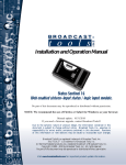
INC
®
Installation and Operation Manual
ADCS-III
Analog to Digital Converter and Switcher
Manual update 08/22/2007
Firmware Version 1.04
Due to the dynamic nature of product design, the information contained in this
document is subject to change without notice. Broadcast Tools, Inc., assumes no
responsibility for errors and/or omissions contained in this document. Revisions
of this information or new editions may be issued to incorporate such changes.
Broadcast Tools® is a registered trademark of Broadcast Tools, Inc.
Copyright, 1989 - 2005 by Broadcast Tools, Inc. All rights reserved.
No part of this document may be reproduced or distributed without permission.
Visit www.broadcasttools.com for important product update information.
ADCS-III Installation and Operation Manual
INTRODUCTION
Thank you for your purchase of the Broadcast Tools® Analog to Digital
Converter and Switcher, which we will refer to throughout the manual as the
ADCS-III. We’re confident this product will give you many years of dependable
service. This manual is intended to give you all the information needed to install
and operate the product.
SAFETY INFORMATION
Only qualified personnel should install Broadcast Tools® products. Incorrect or
inappropriate use and/or installation could result in a hazardous condition.
Broadcast Tools, Inc., is unable to support NON-Broadcast Tools software/hardware or
NON-Broadcast Tools computer hardware/software problems. If you experience these
problems, please research your hardware/software instruction manuals or contact the manufacturers technical support department.
WHO TO CONTACT FOR HELP
If you have any questions regarding your product or you need assistance, please contact your distributor from whom you purchased this equipment.
CAUTION!
Broadcast Tools®
Products, as with any
electronic device, can
fail without warning.
Do not use this product
in applications where a
life threatening condition
could result due to failure.
NOTE:
This manual should be
read thoroughly before
installation and operation.
If you would like more information about Broadcast Tools® products, you may
reach us at:
Broadcast Tools, Inc.
131 State Street
Sedro-Woolley, WA 98284-1540 USA
Voice: 360.854.9559
Fax: 866.783.1742
Internet Home Page: www.broadcasttools.com
E-mail:
[email protected]
WEBSITE:
Visit our web site for
product updates and
additional information.
THANK YOU FOR CHOOSING
BROADCAST TOOLS® BRAND PRODUCTS!
SECTION TITLE
e-mail: [email protected] voice: 360.854.9559 fax: 866.783.1742
2
ADCS-III Installation and Operation Manual
Product Description
The ADCS III provides professional quality 24-bit A/D conversion, along with AES
path insertion and interruption functions. The ADCS III may be configured as a
standalone A/D converter or to switch AES or stereo analog inputs into another AES
stream. The ADCS III is a perfect companion for analog EAS encoders/decoders to
be inserted into an AES program stream. The ADCS III is equipped with relay
bypass in case power is removed from the unit. The A/D converter may be configured for sample rates of 44.1 or 48kHz (32kHz may be special ordered) or an external word clock from 32 to 96kHz. Additional features include; balanced stereo analog input, AES input, AES output and remote control via plug-in euroblock connectors. The front panel is equipped with left and right analog input trimmers, overload,
audio presence and power LED indicators. Input transfer switches are provided
along with LED indicators. Most front panel functions and status are available on
the rear panel connector. The ADCS III is powered by a surge protected internal bipolar 15 vdc power supply affording superior headroom and high definition audio.
The ADCS III may be set on a desktop, mounted on a wall or up to three units may
be mounted on the optional RA-1, Rack-Able mounting shelf.
WEBSITE:
Visit our web site for
product updates and
additional information.
DESCRIPTION
e-mail: [email protected] voice: 360.854.9559 fax: 866.783.1742
3
ADCS-III Installation and Operation Manual
Installation
Please examine your ADCS-III carefully for any damage that may have been sustained during shipping. If any is noted, please notify the shipper immediately and
retain
the
packaging
for
inspection
by
the
shipper.
The package contains the ADCS-III, 16 VAC @ 600 ma wall power transformer and
this manual.
Installation of the ADCS-III in high RF environments should be performed with
care. Shielded cable is suggested for all audio connections. All shields should be
tied to the “G” Ground terminals. The station ground should be connected to the
chassis ground screw located on the far right side of the ADCS-III as viewed from
the rear. It is recommended that all cables connected to the ADCS-III be looped
through ferrite cores to suppress RF. Surge protection with RF filtering such as the
Tripp-Lite “ISOBAR 4 or 6” is also suggested for the wall transformer.
To gain access to the ADCS-III components, remove power and the top cover
allen screw. When the configuration is completed, reinstall the cover, screw
and power.
L/R Analog Inputs
Hi Z, active balanced. Connect your source equipment to the
left/right input - and + terminals on the plug-in euroblock
connector. For monaural sources, tie the left and right inputs
together. Be sure to observe correct phasing. NOTE: If the
source feeding the ADCS III is unbalanced, install a jumper
between Lt- or Rt- terminal and GND.
AES Input 1
Connect your main AES source equipment to this plug-in
euroblock connector. When used as an EAS insert switcher,
this would normally be the feed from your source equipment.
AES Output
Connect this plug-in euroblock connector to the AES input on
your processing equipment.
Word clock input
Balanced word clock input. Accepts all standard digital audio
sample rates from 32 to 96kHz. SW3-2 & SW3-3 must be
configured to activate this input.
Remote Control
The plug-in euroblock connector provides access to the front
panel input selection switches and a
SPDT input tally relay. Applying a closure across terminals 1A & 1B will select
AES input 1. Applying a closure across terminals 2A & 2B
will select the analog input. JP1 is used to configure AES
input 1 opto-isolator for either wet or dry operation. The facINSTALLATION
e-mail: [email protected] voice: 360.854.9559 fax: 866.783.1742
4
ADCS-III Installation and Operation Manual
tory setting is DRY, which accepts dry contact closures, open
collectors, etc. In this configuration, 1A is ground and 1B is
the cathode of the opto-led. To configure for wet operation (5
to 24vdc), move the jumper on JP1 to pins 2 & 3. JP2 is used
to configure the analog inputs opto-isolator for either wet or
dry operation. The factory setting is DRY, which accepts dry
contact closures, open collectors, etc. In this configuration,
2A is ground and 2B is the cathode of the opto-led. To configure for wet operation (5 to 24vdc), move the jumper on JP2
to pins 2 & 3.
Remote input tally is available from the SPDT relay. The terminals are labeled N.O., CM and N.C. When AES Input 1 is
selected, there will be continuity between the N.C. and CM
contacts.
WEBSITE:
Visit our web site for
product updates and
additional information.
INSTALLATION
e-mail: [email protected] voice: 360.854.9559 fax: 866.783.1742
5
ADCS-III Installation and Operation Manual
Programming
“Setup” DIPSwitch settings.
Note: When changing SW3, be sure to press the front panel recessed “reset” switch.
SW3-1
OFF: 44.1 kHz sample rate (factory default).
ON:
48 kHz sample rate. May be special ordered for 32 kHz.
SW3-2
OFF: External Clock
ON:
Internal (factory default).
SW3-3
OFF: External clock, 30 to 59kHz (factory default).
ON:
External clock, 59 to 96kHz.
SW3-4
Feature creep
“Options” logic operation DIPSwitch. SW4 sets the mode of operation in binary format.
NOTE: All switches (and/or opto’s) have a 50ms debounce.
Mode 0:
Flip Flop mode 0 (Last source selected). The unit will power-up for the
first time with AES Input one (default) selected. To select the analog input
two, press the front panel input two push button and/or activate the remote
control terminals. To select AES Input one, press the front panel input one
push button and/or activate the remote control terminals. The non-volatile
memory will store the state of the currently selected source and will return
to this state after a power outage (referred to as “Last Source Selected”).
Mode 1: Flip Flop mode one (User selected source). The unit will power-up for
the first time with AES Input one selected. To select analog Input two,
press the front panel input two push button and/or activate the remote
control terminals. To select AES Input one, press the front panel input
one push button and/or activate the remote control terminals. The nonvolatile memory will store the present state when the desired front panel
input switch is held for 3 seconds. The front panel input indicator led’s
should flash twice indicating that the command is accepted. During a
power outage it will always return to this input.
Mode 2: Momentary/Sustained mode. This is the preferred mode for EAS insertion control.
Operation prior to 11-29-2006: In this mode, the unit will always
power-up with AES Input one selected. The front panel input selection
push buttons and remote control terminals 2A and 2B are disabled. When
remote control terminals 1A and 1B are closed, the analog input (two) is
activated. When the closure is removed, AES input one is selected.
Operation after 11-29-2006: The unit will power-up for the first time
with AES Input one selected. To select the analog input two, press the
PROGRAMMING
e-mail: [email protected] voice: 360.854.9559 fax: 866.783.1742
6
ADCS-III Installation and Operation Manual
front panel input two push button. To select AES Input one, press the
front panel input one push button. The non-volatile memory will store the
state of the currently selected source and will return to this state after a
power outage (referred to as “Last Source Selected”). When remote control terminals 1A and 1B are closed, analog input (two) is activated.
When the closure is removed, the state of the last selected source prior to
the remote input 1A and 1B being activated will be selected.
NOTE: When remote control terminals 1A and 1B are not active
(closed), the front panel input push button switches are active.
Mode 3: Feature creep.
WEBSITE:
Visit our web site for
product updates and
additional information.
SECTION TITLE
e-mail: [email protected] voice: 360.854.9559 fax: 866.783.1742
7
ADCS-III Installation and Operation Manual
Operation
Power
Insert the power plug into the power jack on the ADCS-III
and the wall transformer into the proper AC outlet. Verify
that the power LED is lit.
Act
The ACTivity LED is set to trip at levels above –5dBu.
Clip
This led is set to illuminate when the input level is at +20dBu.
The clip led should occasionally flash with normal program
activity.
LT Lvl / RT Lvl
Adjust these controls to the desired AES output level.
WEBSITE:
Visit our web site for
product updates and
additional information.
OPERATION
e-mail: [email protected] voice: 360.854.9559 fax: 866.783.1742
8
ADCS-III Installation and Operation Manual
Specifications
Analog Input Level
0dBu to +24dBu.
+4dBu analog input provides -20dBfs AES output
when adjusted with the front panel trimmers.
Analog Input Impedance
10K Ω balanced.
Frequency Response
10 to 20kHz +/- 0.5dB.
Distortion
<.001%HD / IMD
Noise
<108dB Ref
AES Output Impedance
110 Ω, balanced (A/D enabled). Passive when
AES input 1 is selected.
Word clock input impedance
75 Ω, balanced
Word clock input level
5 volts
Word clock input range
32 to 96kHz
Opto-Isolated remote inputs
Dry, 5 volt @ 6ma. Wet, 5 to 24vdc.
Tally relay
SPDT, 30Vdc/1 amp.
Connectors
AES, analog Inputs/Outputs and remote control
connections: Plug-in euroblock screw terminals
Word Clock; BNC
Power Requirement
16 Vac, 600 ma, wall transformer, Supplied.
Surge protected power supply.
Size
1/3” rack space, Painted chassis w/ 4 – 6-32
mounting holes.
Weight
2.0 lb.
Options
RA-1, Rack Shelf. 1 RU. / 220 Vac 50-60 Hz CE
wall transformer.
WEBSITE:
Visit our web site for
product updates and
additional information.
SPECIFICATIONS
e-mail: [email protected] voice: 360.854.9559 fax: 866.783.1742
9
ADCS-III Installation and Operation Manual
LIMITED WARRANTY
The term “Buyer” as used in this document refers to and includes both (but only) (a) any person or entity who acquires such an item for
the purpose of resale to others (i.e., a dealer or distributor of an item), and (b) the first person or entity who acquires such an item for
such person’s or entity’s own use.
Broadcast Tools warrants to each Buyer of any item manufactured by Broadcast Tools that the item will be free from defects in materials and workmanship at the time it is shipped by Broadcast Tools if the item is properly installed, used and maintained.
EXCLUSIVE REMEDIES
If Broadcast Tools is notified, in writing, of a failure of any item manufactured by Broadcast Tools to conform to the foregoing Limited
Warranty within one (1) year following the date of the Buyer’s acquisition of the item, and if the item is returned to Broadcast Tools in
accordance with Broadcast Tools’ instructions for confirmation by inspection of the defect (which at Broadcast Tools’ election may
include, without limitation, a requirement that the Buyer first obtain a Return Authorization number from Broadcast Tools, that the Buyer
furnish proof of purchase in the form of an invoice and/or receipt, and that the Buyer prepay all freight charges associated with any return
of the item to Broadcast Tools using such freight service as Broadcast Tools reasonably may specify), Broadcast Tools will repair or
replace the defective item, or will refund the purchase price paid by the Buyer for the item. Broadcast Tools shall have the exclusive
right to choose between these alternative remedies.
NO OTHER WARRANTIES OR REMEDIES
TO THE MAXIMUM EXTENT PERMITTED BY APPLICABLE LAW, BROADCAST TOOLS AND ITS SUPPLIERS DISCLAIM ALL OTHER
WARRANTIES, EITHER EXPRESS OR IMPLIED, INCLUDING BUT NOT LIMITED TO IMPLIED WARRANTIES OF MERCHANTABILITY OR FITNESS FOR A PARTICULAR PURPOSE; AND THE FOREGOING ALTERNATIVE REMEDIES SHALL BE EXCLUSIVE OF
ALL OTHER REMEDIES. THIS LIMITED WARRANTY GIVES YOU SPECIFIC LEGAL RIGHTS. YOU MAY HAVE OTHER RIGHTS,
WHICH VARY FROM STATE/JURISDICTION TO STATE/JURISDICTION.
NO LIABILITY FOR CONSEQUENTIAL DAMAGES
TO THE MAXIMUM EXTENT PERMITTED BY APPLICABLE LAW, NEITHER BROADCAST TOOLS NOR ANY OF ITS SUPPLIERS
SHALL HAVE ANY LIABILITY FOR ANY SPECIAL, INCIDENTAL, INDIRECT, CONSEQUENTIAL OR PUNITIVE DAMAGES WHATSOEVER (INCLUDING, WITHOUT LIMITATION, ANY DAMAGES FOR LOST PROFITS, BUSINESS INTERRUPTION, LOSS OF DATA OR
INFORMATION, COST OF CAPITAL, CLAIMS OF CUSTOMERS, OR ANY OTHER PECUNIARY LOSS) ARISING OUT OF THE USE
OF OR THE INABILITY TO USE ANY ITEM SUPPLIED BY BROADCAST TOOLS, EVEN IF BROADCAST TOOLS HAS BEEN
ADVISED OF THE POSSIBILITY OF SUCH DAMAGES HAVE ANY LIABILITY FOR ANY SPECIAL, INCIDENTAL, CONSEQUENTIAL,
EXEMPLARY OR PUNITIVE DAMAGES. THIS LIMITATION OF LIABILITY APPLIES WHETHER A CLAIM IS ONE ALLEGING
BREACH OF A CONTRACT OR WARRANTY, NEGLIGENCE OR OTHER TORT, FOR THE VIOLATION OF ANY STATUTORY DUTY,
THE FAILURE OF ANY LIMITED OR EXCLUSIVE REMEDY TO ACHIEVE ITS ESSENTIAL PURPOSE, OR ANY OTHER CLAIM OF
ANY NATURE. BECAUSE SOME STATES AND JURISDICTIONS DO NOT ALLOW THE EXCLUSION OR LIMITATION OF LIABILITY
FOR INCIDENTAL OR CONSEQUENTIAL DAMAGES, THIS LIMITATION MAY NOT APPLY TO YOU.
Broadcast Tools, Inc.
131 State Street
Sedro-Woolley, WA 98284 • USA
360.854.9559 voice • 866.783.1742 fax
[email protected] e-mail
www.broadcasttools.com website
LIMITED WARRANTY
e-mail: [email protected] voice: 360.854.9559 fax: 866.783.1742
10