1
QuickDesigner 2 Software Manual
Quick Tour
4.7 Test the Program
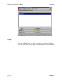
When the application download is complete, the MotionBASIC direct mode
prompt will return.
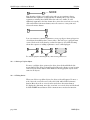
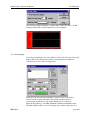
Configure the ORION DIO point 1 (DIO@(1)) as an output, and DIO point 2
(DIO@(2)) as an input. In MotionBASIC 3.x, type IO.MODE@(1)="OI" at the
MotionBASIC direct mode prompt. In MotionBASIC 4.x, configure DIO@(1)
as an input and DIO@(2) as an output in the Unit Settings of the MotionDesk
Project Navigator, and Sync the project. Insert a DC output module and DC
input module into DIO points 1 and 2 respectively. Wire these I/O points
such that asserting DIO point 1 also asserts DIO point 2.
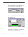
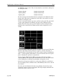
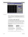
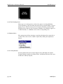
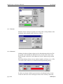
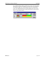
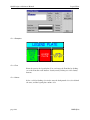
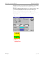
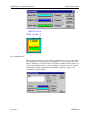
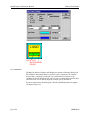
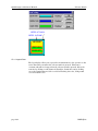
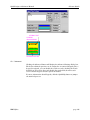
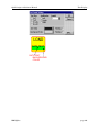
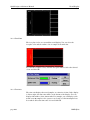
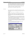
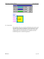
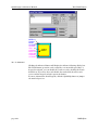
Pressing the push-button on the QuickPanel will turn on DIO 1 (output) on. If
DIO 1 is properly wired to DIO2, DIO 2 will be asserted. The Pilot Light tag
variable for the push-button is tied to OD0002, so it will go on. The
push-button was selected to be a toggle type button. Pressing the push-button
again will cause OD0001 to be set to 0 and OD0002 to be set to 0. The pilot
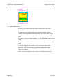
light section of the push-button will go out.
You had to read about thirteen pages of this tutorial in order to create your
first push-button. It might have taken you about ten minutes to complete the
exercise. Now that you are familiar with the operations, it should take you a
minute or two to create another button or pilot light. Just think how much
time and money you have saved! You can add an operator to your control
panel in less than two minutes with no wiring changes! That's QuickPanel!
page 24
MMI-QD2a