1
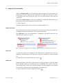
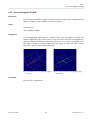
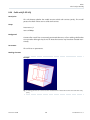
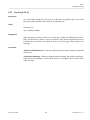
LiteComply Published 2015-12-04 LiteComply 1.5.1 User Guide Contents 1 Preface .............................................................................................................................................. 5 1.1 About this document ....................................................................................................................... 5 1.2 Notation conventions in this document ......................................................................................... 5 1.3 Legal notices ..................................................................................................................................... 5 1.4 Contacting Transcat PLM ................................................................................................................ 5 2 Basics ................................................................................................................................................ 6 2.1 About LiteComply ............................................................................................................................. 6 2.2 JT compatibility ................................................................................................................................. 6 2.3 Concepts ........................................................................................................................................... 6 3 User interface overview .................................................................................................................... 8 3.1 Plug-ins and perspectives ................................................................................................................ 8 3.2 LiteComply perspective .................................................................................................................... 9 4 Check in interactive mode .............................................................................................................. 13 5 Check in batch mode ...................................................................................................................... 14 5.1 Prepare a batch check .................................................................................................................... 14 5.1.1 Introduction ............................................................................................................................... 14 5.1.2 Documents to check ................................................................................................................. 15 5.1.3 Report settings .......................................................................................................................... 16 5.1.4 Console output .......................................................................................................................... 19 5.1.5 Callbacks .................................................................................................................................... 19 5.1.6 Utility functions for batch input ................................................................................................ 19 5.1.6.1 Util.xslify() ............................................................................................................................ 19 5.1.6.2 Util.scandir() ........................................................................................................................ 20 5.1.6.3 Util.readTextFile() ................................................................................................................ 21 5.1.6.4 Util.writeTextFile() ............................................................................................................... 21 5.2 Run a batch check .......................................................................................................................... 21 6 Analysis of check results ................................................................................................................ 22 7 Reports ............................................................................................................................................ 24 Transcat PLM 2 LiteComply 1.5.1 8 Rules ............................................................................................................................................... 25 8.1 At least one solid in part ................................................................................................................ 25 8.2 Body type ........................................................................................................................................ 26 8.3 BRep type ........................................................................................................................................ 27 8.4 BSpline surface with analytical shape ............................................................................................ 28 8.5 Compare LOD to solid/shell .......................................................................................................... 30 8.6 Compare solid/shell to LOD .......................................................................................................... 32 8.7 Component unit ............................................................................................................................. 34 8.8 Document link ................................................................................................................................ 35 8.9 Element outside bounding box [O-CM-OB] .................................................................................. 36 8.10 Empty domain ................................................................................................................................ 38 8.11 Folded surface [G-SU-FO] .............................................................................................................. 39 8.12 Free pixel area ................................................................................................................................. 41 8.13 Inconsistent topological data ........................................................................................................ 42 8.14 Isometric positioning matrix .......................................................................................................... 43 8.15 Item existence ................................................................................................................................. 44 8.16 JT file version .................................................................................................................................. 45 8.17 Large face edge gap [G-LO-LG] ...................................................................................................... 46 8.18 Large face gap (G0 discontinuity) [G-SH-LG] ................................................................................ 47 8.19 Large face edge to surface gap [G-FA-EG] ..................................................................................... 49 8.20 Large Vertex Gap [G-FA-VG] ........................................................................................................... 51 8.21 Multi-domain solid/shell [G-SO-MU] ............................................................................................ 52 8.22 Non-tangent faces (G1 discontinuity) [G-SH-NT] ......................................................................... 53 8.23 Over-used edge [G-SH-NM] ........................................................................................................... 55 8.24 Procedural geometrical element .................................................................................................... 56 8.25 Rational geometrical element ........................................................................................................ 57 8.26 Solid void [G-SO-VO] ..................................................................................................................... 58 8.27 Tiny face [G-FA-TI] .......................................................................................................................... 59 8.28 Tiny face edge [G-ED-TI] ................................................................................................................. 61 8.29 Tiny solid [G-SO-TI] ........................................................................................................................ 62 Transcat PLM 3 LiteComply 1.5.1 9 Application settings ........................................................................................................................ 64 9.1 Local settings .................................................................................................................................. 64 9.2 Read preferences from file ............................................................................................................. 65 9.3 LiteBox3D command line arguments ............................................................................................ 67 9.4 Logging ........................................................................................................................................... 67 10 Appendix ......................................................................................................................................... 70 10.1 Definition of the date and time format string ............................................................................... 70 Transcat PLM 4 LiteComply 1.5.1 Preface About this document 1 1.1 Preface About this document This user manual explains how to check and analyze JT models and other files with LiteComply. 1.2 Notation conventions in this document CAUTION: A notice marked with CAUTION indicates that a certain action may have unwanted consequences, such as loss of data. 1.3 Legal notices Copyright Transcat PLM 2015. LiteComply includes open source software components. For a full list and the terms and conditions, see the annex to this documentation, “Open Source Software – list and licenses” in the doc subdirectory of the installed product. The filename of the annex is ANNEX_Open_Source_Software_List_and_Licenses.pdf. 1.4 Contacting Transcat PLM Send feedback Your feedback helps us improve Lite3D products. Please send your feature requests, bug reports, questions or comments to: E-Mail: [email protected] Support hotline Phone: +49 721 9704335 E-Mail: [email protected] Website http://www.transcat-plm.com Postal address Transcat PLM GmbH Am Sandfeld 11c 76149 Karlsruhe Germany Transcat PLM 5 LiteComply 1.5.1 Basics About LiteComply 2 Basics 2.1 About LiteComply LiteComply is a tool for compliance testing based on custom rules. LiteComply can check the structure, geometry, and metadata of JT models, and various aspects of TIFF files. You can use LiteComply for interactive checks inside the LiteBox3D viewer, or as a command-line tool for batch operation. 2.2 JT compatibility Lite3D products use an implementation based on the ISO specification of the JT format (ISO/PAS 14306:2011 and ISO/IS 14306). Supported data formats: • JT file format versions 8.0 to 9.5 • PLMXML assemblies • STEP AP242 XML assemblies The display of ULP geometry data (Ultra-Lightweight-Precise) is currently not supported. 2.3 Concepts The following definitions explain basic concepts relevant to LiteComply users. Configurations A configuration is a testing specification in LiteComply. A configuration contains the definition of rules, item selections, conditions, ratings, and other settings. To create and edit configurations, use LiteComply Configuration Editor, which can be installed additionally. Rules A rule defines model characteristics to be checked. The result of a particular rule is expressed as a rating. Ratings The result of a particular rule is expressed as a rating. If the model passes the rule, the rating is “Passed”. If the model does not fulfill the rule, an error rating is applied. There can be various error ratings in order to classify data quality issues by severity. Model assessment The model assessment corresponds to the most critical rating of any failed rule. Transcat PLM 6 LiteComply 1.5.1 Basics Concepts Model type The model type is a special property of the configuration that is used to display static or conditional information in the check result. The definition of the model type depends on the configuration. When used together with check conditions, the model type can be an indicator for the model that has been checked, and for the set of rules applied in the check run. Transcat PLM 7 LiteComply 1.5.1 User interface overview Plug-ins and perspectives 3 User interface overview This section provides an overview of the LiteComply user interface which is integrated into LiteBox3D. Common functions of LiteBox3D: LiteBox3D User Guide, Orientation. LiteComply batch mode: Check in batch mode, page 14 LiteComply configuration editor: The separate user guide for LiteComply Configuration Editor is located in the doc directory of the configuration editor installation. 3.1 Plug-ins and perspectives LiteBox3D can be extended with plug-ins that provide additional tools. These additional tools may be available in different views, or perspectives, within the same application window. The initial perspective after startup is LiteBox3D. Perspectives toolbar You can switch between perspectives by clicking a button on the perspectives toolbar. LiteBox3D In this perspective, you can open and view JT models. If no Lite3D plug-ins are installed, this is the only perspective available. LiteDrop Interactive In this perspective, you can delete items from the current 3D model. To open the LiteDrop configuration editor, click the black arrow next to the icon, then choose “Configuration” from the button menu. xCompare In this perspective, you can compare JT models. To open the xCompare configuration editor, click the black arrow next to the icon, then choose “Configuration” from the button menu. LiteComply In this perspective, you can test JT models for compliance with data quality rules. If no license has been granted for a certain plug-in, the corresponding button is unavailable and marked with a special icon . Transcat PLM 8 LiteComply 1.5.1 User interface overview LiteComply perspective 3.2 LiteComply perspective While in LiteComply perspective, only the active model is available. It is not possible to activate a different model, to open a model, or to close the current model. For these actions, first switch to LiteBox3D perspective. Model toolbar Perspectives toolbar Main toolbar LiteComply toolbar 3D controls Model view or rules view Details pane Status bar Geometry view Main toolbar “About” Show the versions of LiteBox3D and installed plug-ins. “Change settings” Show the “Preferences” dialog where you can change application settings. LiteBox3D User Guide, Application settings “Help” Show the help browser. Model toolbar Use the tools on the model toolbar to change the geometry view, take screenshots, or print model views. LiteBox3D User Guide, Model toolbar Transcat PLM 9 LiteComply 1.5.1 User interface overview LiteComply perspective LiteComply toolbar “Run check” Check the active model. While the check is running, the icon changes to a spinning wheel. “Rules view” Show the check results arranged by rule. The rules view is empty if the check has not been run yet. “Model view” Show elements in hierarchical order. Check results are shown as color markings in the tree. Additional information on the selected item is shown in the Details pane. “Auto-reframe” Automatically reframe geometry view to the item selected in the model tree. “Show marking elements” If available, show marking elements for the geometry error selected in the model tree. Display by result To display rules or elements by check result, click the button and choose an option from the button menu: • “Show All”: Show all rules and items. • “Show Passed”: Show only items which have passed. • “Show Failed”: Show only items which have failed. LiteComply tree views The LiteComply tree views show the results of a check run. You can switch between model view and rules view. Results are cleared from the tree views when you choose a different configuration. “Model view” This view shows the model structure including properties, LOD and BRep elements, and PMI containers. Check results for particular elements, where available, are shown as colors markings. Detailed results for the selected element are shown in the “Details” pane. “Rules view” In this view, results are arranged by rule. Rules are sorted by priority of their rating in descending order. Rules with same ratings are sorted alphabetically. The rules view is empty if the model has not been checked yet with the selected configuration. Transcat PLM 10 LiteComply 1.5.1 User interface overview LiteComply perspective Fig. 1: Results arranged by rule in rules view Interacting with the LiteComply tree views • To expand or collapse a branch, click the triangle next to the respective item. • To expand or collapse the entire tree, right-click a tree item and choose “Expand all” or “Collapse all” from the context menu. • To filter the tree by name, type into the filter text box above the tree. The filter is not case-sensitive. You can use wildcards. The asterisk * stands for any number of characters, the question mark ? for any single character. To show the entire tree again, click the “Clear” button . Fig. 2: The filter expression “cam” shows only items whose names contain “cam”, and their parents. Rules context help You can view help for a particular rule in the following ways: • In rules view: Right-click a rule and choose “Help” from the context menu (Fig. 3). • In model view: Select an item. Choose a rule in the “Details” pane. Right-click the rule and choose “Help for …” from the context menu (Fig. 4). If you switch between configurations while a help window is open, you need to reload the help window manually to update the table of contents. To do this, click into the help window, then press the [F5] key. Transcat PLM 11 LiteComply 1.5.1 User interface overview LiteComply perspective Fig. 3: In rules view, help is available on the context menu for rules Fig. 4: In model view, help is available on the context menu for rules. Rules for the selected item are shown in the “Details” pane. Geometry view Use the mouse to zoom and rotate the model in 3D geometry view. LiteBox3D User Guide, Geometry view Transcat PLM 12 LiteComply 1.5.1 Check in interactive mode 4 Check in interactive mode With LiteComply in interactive mode, you can check the current model and view the results within LiteBox3D. Follow these steps to run a check in interactive mode. 1 Open the model in LiteBox3D. 2 Click the LiteComply button on the Perspectives toolbar. The model is shown in LiteComply perspective. 3 Choose a check configuration in the “Configuration” list box. 4 Depending on an application setting, the report file name is filled in automatically. If the “Report file name” field is editable and empty, specify a file path and name for the report. 5 Click “Run check” to check the model. While the check is running, the icon changes to a spinning wheel. You can observe the progress in rules view which is built up successively. The results are displayed in the tree view. Next step: Analysis of check results, page 22 TIP • If the “Configuration” list box is empty, go to “Preferences” > “LiteComply”, and add the path to the required configuration. “Configuration paths”, page 64 • If you add configurations to a referenced directory, you need to restart LiteBox3D for these configurations to become available. • If you edit a configuration while the LiteComply session is open, changes are not immediately available in the LiteComply session. Before you can use the updated configuration, choose it again from the list box. Transcat PLM 13 LiteComply 1.5.1 Check in batch mode Prepare a batch check – Introduction 5 Check in batch mode You can run LiteComply checks in batch mode from the command line. Batch mode is useful for checking a large number of models in an automated sequence. INFO: A beta version of the browser-based LiteComply batch interface is included with the LiteComply configuration editor. 5.1 5.1.1 Prepare a batch check Introduction All settings for a batch check are defined in a batch input file. You can create and edit batch input files with a text editor. A sample batch input file batch.qml is included in the LiteComply installation. General syntax rules and conventions • Single-line comments start with //. • Multi-line comments start with /* and end with */. • In file paths, you can use a single slash or a double backslash as the path separator: "c:/models/model1.jt" "c:\\models\\model1.jt" • Note the difference between paths and URLs: "c:/models/model1.jt" "file:///c:/models/model1.jt" // Path // URL • For more details about the file format, see the Qt QML reference (only recommended for expert users). Search the internet for “Qt 5.5 QML reference”. Minimal batch input file A minimal batch input file requires the following entries: • the import statements • the BatchJob block • URL of the configuration (configURL) • report path (reportPath) Transcat PLM 14 LiteComply 1.5.1 Check in batch mode Prepare a batch check – Documents to check • list of documents to check (docs) import QtQml 2.2 import com.transcat.tca3dn.comply 1.0 import "qrc:/com/transcat/tca3dn/comply" BatchJob { configUrl: "file:///C:/litecomply/configs/a.lcc" reportPath: "C:/temp/report.lcr.xml" docs: [ "T:/models/model_123.jt", "T:/models/model_456.jt", "C:/temp/assembly.plmxml" ] } 5.1.2 Documents to check You can select the documents to be checked in various ways. The documents can be listed in the input file. The list is enclosed in square brackets. Items are separated by comma. docs: [ "T:/models/model_123.jt", "T:/models/model_456.jt" ] By default, the globally defined configuration and report path are used. To specify a different configuration and report path with a particular model, use a structure containing these properties: • doc (document path, required) • reportPath (report path, optional) • configUrl (configuration path, optional) docs: [ ... { doc: "<doc-path>" reportPath: "<report-path>" configUrl: "<config-url>" }, ... ] Instead of listing all documents, you can read files from a directory. Use a file type mask to restrict the selection. Transcat PLM 15 LiteComply 1.5.1 Check in batch mode Prepare a batch check – Report settings docs: Util.scandir(<path>,<ext>,<sub>) <path>: <ext>: Path of the directory to scan. File name mask or list of file name masks. <sub>: To include subdirectories, set this parameter to true. To exclude subdiretories, set false or omit this parameter. The list of files can also be read from a separate text file. To read a text file with one file path per line, use the following command: docs: Util.readTextFile(<path>).split("\n") Util.scandir(), page 20 Util.readTextFile(), page 21 5.1.3 Report settings The reports settings listed below are optional and can be added to the BatchJob block. The settings marked as “default” apply if the property is not set. Report settings Property Description and values language Language used in the report: "de": reportEnabled German "en" (default): English true (default): Create reports false: Transcat PLM Do not create reports 16 LiteComply 1.5.1 Check in batch mode Prepare a batch check – Report settings Report settings (continued) Property Description and values reportAutoRename true (default): Report files use the base name of the checked file, but with exten- sion .lcr.xml. false: Reports use the file name from the reportPath property, followed by a sequence number. Example reportPath: "c:/litecomply/reports/batch_doc.lcc.xml" reportAutoRename: false With these settings, reports are named batch_doc1.lcr.xml, batch_ doc2.lcr.xml, and so on. enableLogging(path) Use this function to write a batch session log file to the specified path (parameter). The batch session log contains an overview of the check results for every single model. If the given path does not exist, LiteComply will try to create it. Place this function call in the onBegin section. The file format of the session log depends on the specified file extension: • For file extension .xml, write the session log as XML. • For file extension .json or any other file extension, write the session log as JSON. BatchJob { configUrl: "..." reportPath: "..." ... onBegin { enableLogging("file://c:/comply/log/batch.xml") /* alternatively as JSON: enableLogging("file://c:/comply/log/batch.json") enableLogging("file://c:/comply/log/batch.log") */ } Transcat PLM 17 LiteComply 1.5.1 Check in batch mode Prepare a batch check – Report settings Report settings (continued) Property Description and values xsl4html Set this property to create additional HTML reports for every document in the batch and an additional batch session log in HTML. xsl4html: "c:/comply/resources/litecomply.xslt" Set the property to the file name of the stylesheet. The default stylesheet for HTML generation included with LiteComply is called litecomply.xslt. If you specify the file name without a path, the file is expected in the LiteComply application directory. xsl4xml Set this property to copy the XSL stylesheet for viewing XML reports in a browser to the report directory. xsl4xml: "c:/comply/resources/litecomply.xslt" Set the property to the file name of the stylesheet. The default stylesheet for browser display included with LiteComply is called litecomply.xslt (same as for generating HTML files). If you specify the file name without a path, the file is expected in the LiteComply application directory. Example For the batch defined below, a batch session log and additional HTML reports are written. The stylesheet for viewing XML reports in the browser is copied to the report directory. import QtQml 2.2 import com.transcat.tca3dn.comply 1.0 import "qrc:/com/transcat/tca3dn/comply" BatchJob { configUrl: "file:///C:/litecomply/configs/a.lcc" reportPath: "C:/temp/report.lcr.xml" docs: [ "T:/models/model_123.jt", "T:/models/model_456.jt", "C:/temp/assembly.plmxml" ] onBegin: enableLogging("C:/temp/session_log.xml") xsl4html: "C:/comply/litecomply.xslt" xsl4xml: "C:/comply/litecomply.xslt" } Transcat PLM 18 LiteComply 1.5.1 Check in batch mode Prepare a batch check – Console output 5.1.4 Console output You can control the amount of information written to the console during a batch run with the verbose property. When set to true, more details are written to the console. verbose: true // verbose: false 5.1.5 Callbacks LiteComply can perform actions at certain points in the course of a batch run. These actions can be defined in special blocks. List of callbacks Property Description and values onBegin: { } Commands in this section are executed when the batch has started, before the first job. This block typically contains the enableLogging() function. onJobStarted: { } Commands in this section are executed every time a job within the batch has started. onJobFinished: { } Commands in this section are executed every time a job within the batch has finished. onEnd: { } Commands in this section are executed after the last job within the batch has finished. onReportFinished: Commands in this section are executed after all reports have been written. { } 5.1.6 5.1.6.1 Utility functions for batch input Util.xslify() Perform an XSL transformation using a given input file and stylesheet. Syntax Util.xslify(<xsl>, <source>, <target>) Transcat PLM 19 LiteComply 1.5.1 Check in batch mode Prepare a batch check – Utility functions for batch input <xsl> Path to the XSL stylesheet. <source> Path to the XML source document. <target> Path to the target document. If the path does not exist, LiteComply will try to create it. Example Transform the XML source document logfile.xml with the stylesheet dbreport.xsl to db.xml: Util.xslify("logfile.xml", "dbreport.xsl", "db.xml"); 5.1.6.2 Util.scandir() Get a list of matching files from a directory. Syntax Util.scandir(<path>, <ext>, <sub>) <path> <ext> Path of the directory to scan. File name mask or list of file name masks. To include subdirectories, set this parameter to true. To exclude subdiretories, set false or omit this parameter. <sub> Example • Get a list of files with extension .jt from directory c:/models and all subdirectories. var files = Util.scandir("c:/Models", "*.jt", true); • Get a list of files with extension .jt or .plmxml from directory c:/models. Do not look into subdirectories. var files = Util.scandir("c:/Models", ["*.jt","*.plmxml"], false); Transcat PLM 20 LiteComply 1.5.1 Check in batch mode Run a batch check 5.1.6.3 Util.readTextFile() Get the contents of a text file. Syntax Util.readTextFile(<path>) <path> Path of the text file. Example Get the contents of the file c:/temp/text.txt. var list_content = Util.readTextFile("c:/temp/text.txt"); 5.1.6.4 Util.writeTextFile() Write text to a file. Syntax Util.readTextFile(<path>,<text>) <path> Path of the text file. If the given path does not exist, LiteComply will try to create it. <text> Text content to write to the file. Example Write a string value to the file c:/temp/text.txt. var tmp = "File is generated automatically.\nTime: 09:45:02" Util.writeTextFile("c:/temp/text.txt", tmp); 5.2 Run a batch check To run a batch check, enter the following command at the command line: litecomply.exe <inputfile> <inputfile> Path and name of the batch input file. Next step: Inspect check results in the report. See Reports, page 24 Transcat PLM 21 LiteComply 1.5.1 Analysis of check results 6 Analysis of check results After an interactive check run has finished, results are shown in the LiteComply tree. Depending on the item selected in the LiteComply tree, additional information is given in the details pane and the geometry view. You can switch between rules view and model view. The results of batch check runs cannot be displayed in LiteBox3D. Please refer to the batch report and the individual reports for each model. Reports, page 24 The following information refers to results of interactive check runs. Model assessment The model assessment, which corresponds to the most critical rating of any failed rule, is displayed as the root node both in rules view and model view. The model type, if set in the configuration, is displayed in the details pane when you select the root node (Fig. 1, Fig. 2). Fig. 1: Model type in the details pane (model view) Fig. 2: Model type in the details pane (rules view) Rules view In rules view, results are arranged by rule. Details for the selected rule or item are displayed in the details pane. The rules view is empty if the model has not been checked yet. To select rules view, click the “Rules view” button . Model view Model view shows the actual model structure including properties, LOD and BRep items, and PMI containers. Checked items are indicated by color marks in the tree. Items without color marks have not been checked. The rules applied to the selected item and their respective results are displayed in the details pane. To select model view, click the “Model view” button Transcat PLM 22 . LiteComply 1.5.1 Analysis of check results Visualization of geometry errors Certain geometry errors can be visualized with marking elements directly in geometry view. Select the “Show marking elements” button to enable the visualization. When you select a geometry item with errors, marking elements are shown. To display the marking elements for a single error, select an item. Failed sub-items, are only available in rules view. Auto-Reframe Select the “Auto-Reframe” button currently selected in the model tree. to reframe the geometry view on the item If both “Auto-Reframe” and “Show marking elements” are selected, the geometry view is reframed on the marking elements (if available) for the selected item. Filter You can filter the tree by result: • “Show failed”: Show only failed items and their parents. • “Show passed”: Show only passed items and their parents. Parents are marked as failed if one or more children are marked as failed. Therefore, you may see parents marked as failed even if the “Show passed” filter is active. General errors Corrupted geometry or other unexpected data might prevent LiteComply from processing a rule. In this case, the rule and item in question are rated as “passed” but marked with a general error. Rules and items with general errors are shown regardless of an active “Show passed” or “Show failed” filter. They are marked with a triangle and exclamation mark (Fig. 3). Fig. 3: General errors shown in rules view with additional information in the details pane. No items to check The message “There are no items to check” in the details pane indicates that the selected rule hasn’t found any items to check in the model. The rule counts as “passed”. Transcat PLM 23 LiteComply 1.5.1 Reports 7 Reports Report name By default, report files are named after the file name of the checked document. The extension .xml is added to the original file name and extension. To name report files manually, deselect the “Always use the model name as report name” option in LiteComply preferences. If the “Report file name” field is empty, no report is created. Display reports in a browser To prepare reports for display in a web browser, a processing instruction with a link to a stylesheet is added to the report. The LiteComply installation includes an XSLT stylesheet named litecomply.xslt. Optionally, LiteComply can create HTML report files in addition to the XML report. The resulting HTML report document is self-contained, which means all information, including images and other resources, is stored in a single HTML file. Transcat PLM 24 LiteComply 1.5.1 Rules At least one solid in part 8 Rules 8.1 At least one solid in part Description This rule detects whether every checked part in the JT model contains at least one solid. Scope Documents: JT Items: Part, Assembly Transcat PLM 25 LiteComply 1.5.1 Rules Body type 8.2 Body type Description This rule checks the types of bodies in a model. Scope Documents: JT Items: XTBRep Parameters “Non-allowed body types” List of body types that are not allowed. The following types may be listed: • “Solid”: Closed topology • “Sheet”: Open topology • “General”: Other types Transcat PLM 26 LiteComply 1.5.1 Rules BRep type 8.3 BRep type Description This rule checks the model for BReps of the XT, JT, and ULP type. The model passes the check if it contains no BReps other than those of the allowed types. Scope Documents: JT Items: JTBRep, XTBRep, ULP Parameters “XT-BRep allowed” If this parameter is set to “yes”, XT BReps are allowed. “JT-BRep allowed” If this parameter is set to “yes”, JT BReps are allowed. “ULP allowed” If this parameter is set to “yes”, ULP BReps are allowed. Transcat PLM 27 LiteComply 1.5.1 Rules BSpline surface with analytical shape 8.4 BSpline surface with analytical shape Description This rule detects BSpline surfaces with analytical shape (plane, cylinder, cone, sphere, torus). Scope Documents: JT Items: JTBRep, XTBRep Details of the check operation In every point, analytical surfaces have characteristic values for minimum and maximum curvature by which they can be identified as plane, cylinder, cone, sphere, or torus. The curvature is defined as the inverse of the curvature radius. Example: In a plane, every point has a minimum and maximum curvature of zero; the curvature radii of a plane are infinite. During the check, the minimum and maximum curvature in the given discretization points of the segments of a BSpline surface are calculated. The BSpline surface has an analytical shape if the characteristic curvatures are found in all discretization points. Messages “Number of discretization points” Number of points per segment in which the geometry is evaluated. “Allowed relative deviation of curvature” Maximum relative deviation between curvature values in discretization points up to which the values are considered identical. Transcat PLM 28 LiteComply 1.5.1 Rules BSpline surface with analytical shape Marking elements Example Fig. 1: The yellow dashed lines indicate the boundary of the face. The underlying BSpline surface has an analytical shape, in this example a cylindrical shape. Transcat PLM 29 LiteComply 1.5.1 Rules Compare LOD to solid/shell 8.5 Compare LOD to solid/shell Description This rule checks whether LOD geometry corresponds to BRep geometry within the specified tolerances. LiteComply reports the following issues: • Unused elements in the LOD, which do not represent any BRep geometry • Corresponding points on LOD and BRep that are too far apart to be considered identical Scope Documents: JT Items: Part Background LiteComply projects points of the LOD onto the BRep geometry. The distance between corresponding points on the LOD and BRep is evaluated. Parameters “LOD identical to BRep within tolerance [mm]” If the distance between LOD points and their projection on the BRep is less than this value, points are considered identical. “LOD similar to BRep within extended tolerance [mm]” If the distance between LOD points and their projection on the BRep is less than this value, the points correspond to each other. If the distance is equal or greater than this value, the LOD point is considered isolated. “Compare which LOD” LODs to compare: • “Smoothest LOD (LOD 0)” • “Roughest LOD” • LOD with specified index “Which points on LOD” Points of the LOD’s triangular grid to project onto the BRep geometry: • “Vertices” • “Vertices + triangle centers” • “Vertices + triangle centers + edge centers” Transcat PLM 30 LiteComply 1.5.1 Rules Compare LOD to solid/shell Marking elements Example Fig. 1: The yellow points mark LOD elements that are sufficiently close to the BRep but not identical. The red points mark LOD elements that exceed the maximum allowed distance from the BRep. Transcat PLM 31 LiteComply 1.5.1 Rules Compare solid/shell to LOD 8.6 Compare solid/shell to LOD Description This rule checks whether, for given BRep geometry, corresponding LOD geometry does exist and is within the specified tolerance. LiteComply reports the following issues: • BRep geometry for which no corresponding LOD geometry is available • Corresponding points on BRep and LOD that are too far apart to be considered identical Scope Documents: JT Items: Part, JTBRep, XTBRep Background LiteComply projects points of BRep geometry onto the LOD. The distance between corresponding points on the BRep and LOD is evaluated. Parameters “Tessellation SAG [mm]” Maximum allowed distance between the surface and polygon segments of the tessellation. A lower value results in a tessellation that is closer to the original surface. “Tessellation step [mm]” Maximum allowed edge length for polygon segments of the tessellation. “Tessellation angle [°]” Maximum allowed angle between the normals of adjacent polygons of the tessellation. INFO: SAG, step, and angle are used internally to create a tessellation of the BRep geometry, which is compared to the LOD geometry. “LOD identical to BRep within tolerance [mm]” If the distance between LOD points and their projection on the BRep is less than this value, points are considered identical. “LOD similar to BRep within extended tolerance [mm]” If the distance between LOD points and their projection on the BRep is less than this value, the points correspond to each other. If the distance is equal or greater than this value, the LOD point is considered isolated. “Compare to LOD” LOD to compare: • “Smoothest LOD (LOD 0)” Transcat PLM 32 LiteComply 1.5.1 Rules Compare solid/shell to LOD • “Roughest LOD” • “N-th LOD” for a LOD with a specific number. “Ignore if LOD does not exist” If this parameter is set to “true”, no error is reported if the selected LOD is missing. If this parameter is set to “false”, an error is reported if the selected LOD is missing. Marking elements Example Fig. 1: The yellow points are measurement points on the BRep geometry for which a sufficiently close point on the LOD does exist. The red points are measurement points on the BRep geometry for which no corresponding point on the LOD has been found within the given tolerance. Transcat PLM 33 LiteComply 1.5.1 Rules Component unit 8.7 Component unit Description This rule checks the whether all components in the checked model use the required unit of measurement. Scope Documents: JT Items: Part, Assembly Parameters “All units must be equal to unit of root item” If this parameter is set to “yes”, the units of all checked components must be equal to the unit of the root item. Otherwise the unit of every component must be one of the allowed units. “Consider case of units” If this parameter is set to “yes”, the names of units must match the required unit also in uppercase/lowercase writing. “Permitted units in model” List of permitted units. The permitted units depend on the configuration. The following units are generally recognized by LiteComply: “millimeters”, “centimeters”, “meters”, “micrometers”, “decimeters”, “kilometers”, “feet”, “yards”, “mils”, “miles” Transcat PLM 34 LiteComply 1.5.1 Rules Document link 8.8 Document link Description This rule checks whether links to other documents can be resolved. The model passes the check if all links can be resolved. Scope Documents: JT Items: Part, Assembly Messages “Item … passed” The link target item with the given path is available. “Item … failed” The linked target with the given path refers to an unavailable resource. Transcat PLM 35 LiteComply 1.5.1 Rules Element outside bounding box [O-CM-OB] 8.9 Element outside bounding box [O-CM-OB] Description This rule checks for geometrical elements positioned outside the defined working area. There must be no geometry outside the defined working area. Scope Documents: JT Items: JTBRep, XTBRep Background Sometimes some elements are created outside the bounding box because of manipulation error or approximation error, etc. This may lead to problems in data exchange and to problems with batch applications (for example, computation of mass properties and bounding box). (Source: SASIG PDQ Guideline) Messages “Tessellation SAG” Maximum distance [mm] between the surface and triangles of the tessellation. A lower value results in a tessellation that is closer to the original surface. “Tessellation step” Maximum edge length [mm] for triangles of the tessellation. A lower value results in a more finely-meshed tessellation. “Tessellation angle” Maximum angle [°] between the normals of adjacent triangles in the tessellation. A lower value better represents uneven surfaces. “Shape of working area” Shape of the working area, which can be one of the following: • “Cube” • “Sphere” • “Cuboid” “Cube half edge length” Half-edge length of a cube-shaped working area. “Sphere radius” Radius of a sphere-shaped working area. “Cuboid X/Y/Z range” Minimum and maximum coordinates along the X, Y and Z axis for a cuboid-shaped working area. “Do not allow elements that are partially outside the bounding box” If “yes”, geometrical elements partially or fully outside the working area are not allowed. If “no”, geometrical elements partially outside the working area are allowed. “Working area centered on geometry bounding box” If “yes”, the working area has been centered on the bounding box of the model geometry. If “no”, the working area has been centered on the origin of the model. Transcat PLM 36 LiteComply 1.5.1 Rules Element outside bounding box [O-CM-OB] Marking elements Example Fig. 1: Marking elements visualizing the working area Transcat PLM 37 LiteComply 1.5.1 Rules Empty domain 8.10 Empty domain Description This rule detects empty domains, that is, topology without faces. The model passes the check if it does not contain empty domains. Scope Documents: JT Items: JTBRep, XTBRep Background Empty domains may cause problems while processing a model. Messages “Domain without faces” The selected item has an empty domain. Transcat PLM 38 LiteComply 1.5.1 Rules Folded surface [G-SU-FO] 8.11 Folded surface [G-SU-FO] Description This rule checks whether the angle between the normals of adjoining surfaces is greater than specified. The model passes the check if the angle does not exceed the specified limit. Scope Documents: JT Items: JTBRep, XTBRep Background Generally, all normal vectors of a surface are shown uniformly facing the same direction, either into the component or out of it. Occasionally, deviations from this behaviour can occur at the edge of surfaces. This may cause problems in surface offset, in tooling path creation, or in other applications. A special case of a twisted surface close to its edge may be found at the tip of a “quasi” triangular patch. This is the case when two boundary curves, which are diverging upon a point, slightly project beyond the point of intersection. (Source: SASIG PDQ Guideline) Parameters “Angle between neighbouring normals greater than” Maximum allowed angle between normals of adjoining surfaces. “Number of discretization points” Number of points per segment and coordinate direction, in which the geometry is evaluated. “Number of adjacent points to check” Number of adjacent points per segment to process. “Check only surface regions covered by faces” If this parameter is set to “yes”, flipped surface normals in unused regions of the surface have been ignored. Transcat PLM 39 LiteComply 1.5.1 Rules Folded surface [G-SU-FO] Marking elements Examples Fig. 1: Marking elements for a folded surface. The yellow dashed lines indicate the boundaries of the faces. The red arrows indicate the direction of the face normals. Fig. 2: Marking elements for a quasi-triangular patch, a special type of folded surface. The yellow dashed lines indicate the boundaries of the faces. The red arrows indicate the direction of the face normals. Transcat PLM 40 LiteComply 1.5.1 Rules Free pixel area 8.12 Free pixel area Description This rule detects whether the TIFF image contains a free area where the title block can be placed. An area is considered free if its color isn’t black. This check is especially designed for black and white images (1-bit color depth), but works with any color depth. Scope Documents: TIFF Items: Part (subimage) Parameters “Width” Required minimum width [mm] of the free area “Height” Required minimum height [mm] of the free area Transcat PLM 41 LiteComply 1.5.1 Rules Inconsistent topological data 8.13 Inconsistent topological data Description This rule detects inconsistent topological data, in particular faces without surfaces and edges without curves. The model passes the check if it does not contain the specified geometrical elements. Scope Documents: JT Items: JTBRep, XTBRep Background The conversion of geometrical data to JT format may be incomplete or otherwise faulty. The underlying surface of a face or the underlying curve of an edge may be missing. Messages “Check which inconsistency” The following elements can be detected: • Faces without surfaces • Edges without curves Transcat PLM 42 LiteComply 1.5.1 Rules Isometric positioning matrix 8.14 Isometric positioning matrix Description This rule checks whether the positioning matrix of parts and assemblies is isometric. The model passes the check if the positioning matrices are isometric. Scope Documents: JT Items: JTBRep, XTBRep, ULP Background The positioning matrix defines the spatial position of a component (part or assembly). The determinant of the positioning matrix is characteristic of the transformations applied to the component: • The determinant is 1 if the component has been positioned using only translations and rotations. The transformation matrix is “properly isometric”. • The determinant is –1 if the component has been positioned using only translations, rotations and inversions. The transformation matrix is “isometric”. • Transformation matrices with determinants other than 1 or –1 do not preserve lengths. • Small deviations from determinants 1 or –1 can occur due to rounding errors. Usually, the positioning matrix is not taken into account when manufacturing a component. Scaled and mirrored instances must exist as proper geometry to be manufactured. Parameters “Tolerance for matrix determinant” Tolerance by which the matrix determinant may differ from 1 in both positive and negative directions. “Ignore matrices for reflections” If this parameter is set to “yes”, matrices for reflections are allowed. Allowed determinants are (1 ± tolerance) and (–1 ± tolerance). If this parameter is set to “no”, matrices for reflections are not allowed. The allowed determinant is (1 ± tolerance). Transcat PLM 43 LiteComply 1.5.1 Rules Item existence 8.15 Item existence Description This rule counts items matching a certain specification, and checks their values. Scope Documents: JT, TIFF Items: Any item types Messages “Invalid item count” The number of items matching the specification is not valid. “Invalid item value” The values of certain items are not valid. Transcat PLM 44 LiteComply 1.5.1 Rules JT file version 8.16 JT file version Description This rule checks the version of the JT file format. Scope Documents: JT Items: Assembly Messages “Allowed versions” Allowed version numbers as specified in the configuration. • Multiple values and ranges are separated by comma. • Ranges are set in brackets. The lower and upper value are separated with a colon. A square bracket indicates that the boundary belongs to the range; a round bracket indicates that the boundary is outside the range. Examples Transcat PLM Single value 9.0 Range including boundaries [8.5:9.0] Range excluding the lower and including the upper boundary (8.5:10] List of values and ranges 9.5, [8.0:9.0) 45 LiteComply 1.5.1 Rules Large face edge gap [G-LO-LG] 8.17 Large face edge gap [G-LO-LG] Description This rule checks whether a gap between face edges is larger than the specified value. The model passes the check if it does not contain large face edge gaps. Scope Documents: JT Items: JTBRep, XTBRep Background Discontinuities in face edges appear as gaps or overlaps. When transferring faces to a less precise system, discontinuities can cause the loss of the face element or the entire topology. Parameters “Maximum allowed distance [mm]” Maximum allowed gap width between adjacent edges of a face. Marking elements Example Fig. 1: The yellow dashed lines indicate the face edge containing large gaps. The red markings indicate the end points next to the gap. In this example, the widest gap is 0.033 mm wide. Transcat PLM 46 LiteComply 1.5.1 Rules Large face gap (G0 discontinuity) [G-SH-LG] 8.18 Large face gap (G0 discontinuity) [G-SH-LG] Description This rule detects large gaps and overlap between adjacent faces. The model passes the check if it does not contain large face gaps. Scope Documents: JT Items: JTBRep, XTBRep Background Position continuity, that is, coincident position within the given accuracy of bounded surfaces within a topology is the most important quality characteristic within every surface group. A permissible discontinuity that is within the bounds of the accuracy can lead to a loss of the topology in the case of a change in the system or in the range of tolerances or can cause some systems to perform an automatic correction (Healing). Because of this, unintentional changes or the formation of new (tiny) elements can occur. (Source: SASIG PDQ Guideline) Fig. 1: Gaps and overlaps between faces of a topology must not exceed the specified size (marked “TOL”). Messages “Tessellation SAG” Maximum distance [mm] between the surface and triangles of the tessellation. A lower value results in a tessellation that is closer to the original surface. “Tessellation step” Maximum edge length [mm] for triangles of the tessellation. A lower value results in a more finely-meshed tessellation. “Tessellation angle” Maximum angle [°] between the normals of adjacent triangles in the tessellation. A lower value better represents uneven surfaces. “Distance greater than” Gaps of a distance greater than the specified value [mm] are considered large gaps. Transcat PLM 47 LiteComply 1.5.1 Rules Large face gap (G0 discontinuity) [G-SH-LG] Marking elements Example Fig. 2: The yellow dashed lines indicate the boundaries of faces forming large gaps. The red markings indicate the gaps. In this example, the widest gap is 0.0233 mm wide. Transcat PLM 48 LiteComply 1.5.1 Rules Large face edge to surface gap [G-FA-EG] 8.19 Large face edge to surface gap [G-FA-EG] Description This rule checks whether the distance between the face boundary and the surface is within the given tolerance. Scope Documents: JT Items: JTBRep, XTBRep Background If the distance between the boundary curve of a face and the surface is too large, the face may get lost. This may occur especially when transferring faces to a more precise system. Parameter “Gap distance greater than [mm]” Maximum allowed distance between face edge and surface. “Check with” The check can be based on tessellation points or discretization points. • “Tessellation points”: The geometry is analyzed in significant points of the tessellation. The tessellation is defined by parameters sag, step, and angle. • “Discretization points”: The geometry is analyzed in a fixed number of points per segment. More points result in higher accuracy, while computation may take longer. “Number of discretization points” Number of points per segment in which the geometry is evaluated. “Tessellation SAG” Maximum distance [mm] between the surface and triangles of the tessellation. A lower value results in a tessellation that is closer to the original surface. “Tessellation step” Maximum edge length [mm] for triangles of the tessellation. A lower value results in a more finely-meshed tessellation. “Tessellation angle” Maximum angle [°] between the normals of adjacent triangles in the tessellation. A lower value better represents uneven surfaces. Transcat PLM 49 LiteComply 1.5.1 Rules Large face edge to surface gap [G-FA-EG] Marking elements Example Fig. 1: Marking elements for a large face edge to surface gap. The dashed yellow line indicates the surface. The solid yellow line indicates the face edge. The red points indicate points in which the distance between face edge and surface exceeds the allowed distance. Transcat PLM 50 LiteComply 1.5.1 Rules Large Vertex Gap [G-FA-VG] 8.20 Large Vertex Gap [G-FA-VG] Description This rule checks whether the distance between vertices and the underlying surface is within the given tolerance. Scope Documents: JT Items: JTBRep, XTBRep Parameter “Maximum allowed distance [mm]” Maximum allowed distance between vertices and the underlying surface. Marking elements Example Fig. 1: Marking elements for a large vertex gap. The red arrow indicates the measured distance between vertex and surface. The measured value of 0.028313 is greater than the maximum allowed distance. Transcat PLM 51 LiteComply 1.5.1 Rules Multi-domain solid/shell [G-SO-MU] 8.21 Multi-domain solid/shell [G-SO-MU] Description This rule detects multi-volume solids and shells consisting of several domains. Scope Documents: JT Items: JTBRep, XTBRep Background Solids consisting of more than one body and shells consisting of several domains should be avoided, as some CAD tools cannot handle this type of geometry. Parameters “Domain type” The rule may look for multi-volume solids, shells, or both: • “Solid” • “Shell” • “Solid and shell” Transcat PLM 52 LiteComply 1.5.1 Rules Non-tangent faces (G1 discontinuity) [G-SH-NT] 8.22 Non-tangent faces (G1 discontinuity) [G-SH-NT] Description This rule checks whether transitions between faces are tangent-continuous. Faces are tangent-continuous if the angle between face normals does not exceed the specified limit. There can be exceptions where tangent discontinuity is intended by design. Fig. 1: The angle between tangents or normals of adjacent faces must be within the specified range (marked “Tol”) Scope Documents: JT Items: JTBRep, XTBRep Parameters “Check with” The check can be based on tessellation points or discretization points. • “Tessellation points”: The geometry is analyzed in significant points of the tessellation. The tessellation is defined by parameters sag, step, and angle. • “Discretization points”: The geometry is analyzed in a fixed number of points per segment. More points result in higher accuracy, while computation may take longer. “Number of discretization points” Number of points per segment in which the geometry is evaluated. “Tessellation SAG” Maximum distance [mm] between the surface and triangles of the tessellation. A lower value results in a tessellation that is closer to the original surface. “Tessellation step” Maximum edge length [mm] for triangles of the tessellation. A lower value results in a more finely-meshed tessellation. “Tessellation angle” Maximum angle [°] between the normals of adjacent triangles in the tessellation. A lower value better represents uneven surfaces. Transcat PLM 53 LiteComply 1.5.1 Rules Non-tangent faces (G1 discontinuity) [G-SH-NT] “Angle greater than” If the angle between face normals exceeds this value, faces are not tangent-continuous. “Angle less than” If the angle between face normals exceeds this value, the discontinuity is intended by design and not considered an error. Marking elements Example Fig. 2: The yellow dashed lines indicate the boundaries of the faces. The red arrow indicates the location where the angle between face normals is 0.1233°, which is greater than the allowed limit. Transcat PLM 54 LiteComply 1.5.1 Rules Over-used edge [G-SH-NM] 8.23 Over-used edge [G-SH-NM] Description This rule checks whether an edge is used by more than two faces. The model passes the check if no edge is used is used by more than two faces. Scope Documents: JT Items: JTBRep, XTBRep Background For the topological explicitness of a surface, every inner face edge must have one explicit neighbouring face, which means it may not have more than one neighbouring edge and therefore is free from bifurcation/junctions. It is, however, acceptable for a face edge to border on several neighbouring face edges, one after the other (“T-type butt joint”). (Source: SASIG PDQ Guideline) Fig. 1: Forbidden branch. The highlighted edge is over-used. Fig. 2: T-joints are allowed. The highlighted edges are allowed. Parameters This rule has no parameters. Transcat PLM 55 LiteComply 1.5.1 Rules Procedural geometrical element 8.24 Procedural geometrical element Description This rule detects procedural elements, in particular blend surfaces and intersection curves. The model passes the check if it does not contain the specified geometrical elements. Scope Documents: JT Items: XTBRep, JTBRep Background Procedural geometrical elements may cause errors during the processing of JT files. This rule can be used to detect and subsequently sort out models containing such data. Messages “Detect which elements” The following elements can be detected: • Blend surfaces only • Intersection curves only • Both blend surfaces and intersection curves Transcat PLM 56 LiteComply 1.5.1 Rules Rational geometrical element 8.25 Rational geometrical element Description This rule detects rational elements, in particular rational BSpline surfaces and curves. The model passes the check if it contains no non-rational geometrical elements. Scope Documents: JT Items: XTBRep, JTBRep Background BSpline surfaces and curves for which no polynomial representation can be calculated may be a cause for corrupted geometry data. Messages “Detect which elements” The following elements can be detected: • Rational BSpline surfaces only • Rational BSpline curves only • Both rational BSpline surfaces and rational BSpline curves Transcat PLM 57 LiteComply 1.5.1 Rules Solid void [G-SO-VO] 8.26 Solid void [G-SO-VO] Description This rule detects whether the model contains solids with cavities (voids). The model passes the check if there are no solids with cavities. Scope Documents: JT Items: XTBRep Background Cavities often result from inaccurately positioned elements, or from adding solid bodies to one another although they do not fit. Note that cavities may have been created intentionally. Parameters This rule has no parameters. Marking elements Example Fig. 1: Marking elements for a solid void. The red dashed lines indicate the outline of the solid with cavity (void). Transcat PLM 58 LiteComply 1.5.1 Rules Tiny face [G-FA-TI] 8.27 Tiny face [G-FA-TI] Description This rule checks whether the face area is smaller than a specified value. The model passes the check if all faces are at least of the specified size. Scope Documents: JT Items: JTBRep, XTBRep Background When changing the system tolerance or transferring a model to a different CAD system, faces with dimensions below a certain threshold might become degenerated. Some interfaces do not transfer such elements at all. As a result, gaps may emerge in the topology. Parameters “Minimum allowed face area” Faces are valid if their face area has at least the specified value [mm²]. “Tessellation SAG [mm]” Maximum allowed distance between the surface and polygon segments of the tessellation. A lower value results in a tessellation that is closer to the original surface. Transcat PLM 59 LiteComply 1.5.1 Rules Tiny face [G-FA-TI] Marking elements Example Fig. 1: Marking elements for a tiny face. The red dashed line indicates the boundary of the tiny face. Transcat PLM 60 LiteComply 1.5.1 Rules Tiny face edge [G-ED-TI] 8.28 Tiny face edge [G-ED-TI] Description This rule checks whether the length of a boundary edge curve is below the given value or within a given interval. Scope Documents: JT Items: XTBRep, JTBRep Parameters “Check with” The check can be based on tessellation points or discretization points. • “Tessellation points”: The geometry is analyzed in significant points of the tessellation. The tessellation is defined by parameters sag, step, and angle. • “Discretization points”: The geometry is analyzed in a fixed number of points per segment. More points result in higher accuracy, while computation may take longer. “Tessellation SAG [mm]” Maximum distance between the surface and polygon segments of the tessellation. Set a lower value for a tessellation that is closer to the original surface. “Length less than [mm]” This is the upper limit of the interval of invalid edge lengths. Edges are considered incorrect if their length is shorter than the specified value. “Length greater than [mm]” Optional parameter. This is the lower limit of the interval of invalid edge lengths. Marking elements Example Fig. 1: Marking elements for a tiny face. The dashed yellow edge between the two red points is shorter than the specified value. Transcat PLM 61 LiteComply 1.5.1 Rules Tiny solid [G-SO-TI] 8.29 Tiny solid [G-SO-TI] Description This rule checks whether the size of a solid is within a given interval or below a given value. The calculation can be based on the volume of solids, or on their size in one, two or all three spatial directions. Scope Documents: JT Items: XTBRep, JTBRep Background Solids that fall short of a particular dimension in two directions in space should be avoided. Depending on the interface and internal accuracy, these elements can cause problems or be lost during the exchange of data. Often these elements may also occur unintentionally during the modeling process (that is, intersection of two solids that only slightly penetrate each other) and cannot be produced. (Source: SASIG PDQ Guideline) Parameters “Dimensions to check” Dimensions by which a tiny solid is detected: • “Volume” • “Bounding box length in one spatial direction” • “Bounding box length in two spatial directions” • “Bounding box length in all spatial directions” “Volume less than [mm³]” If the volume of a solid is less than the specified value, the solid is considered a tiny solid. This parameter is only available for the volume-based calculation. “Length less than [mm]” If a solid is smaller than the specified value in one, two or all spatial directions, it is considered a tiny solid. This parameter is not available for the volume-based calculation. “Mark as failed if a single domain violates the rule” If this parameter is set to “yes”, the domains of a multi-domain solid are checked individually. If this parameter is set to “no”, a bounding box enclosing the multi-domain solid is checked. Transcat PLM 62 LiteComply 1.5.1 Rules Tiny solid [G-SO-TI] Marking elements Example Fig. 1: Marking elements for a tiny solid. The calculated volume of the tiny solid is 0.585 mm3. Transcat PLM 63 LiteComply 1.5.1 Application settings Local settings 9 9.1 Application settings Local settings To change application settings for LiteComply, click the “Change settings” button on the model toolbar. To restore default settings on a particular dialog page, click the “Restore defaults” button. “LiteComply” “Activate LiteComply (request license at startup)” If this option is selected, LiteComply is activated. A license is checked out from the license server as soon as you click “Apply”, and every time you start the LiteBox3D application. “Marking elements color” Marking elements color for geometry. “Error marking elements color” Marking elements color for the visualization of errors. “Configuration paths” Paths to LiteComply configuration files. Configurations in these paths can be selected from the “Check configuration” list box. • “Add path”: Click this button to add the configuration given in the text box. This can be a directory path (for all configurations in the directory), a full path and file name of a configuration, or the URL of a configuration on a web server. You can use environment variables in this field. An entry with resolved environment variables must form a valid file path. Notations of an environment variable are %VAR% or ${VAR}, where “VAR” is the variable name. • “Add file”: Choose a configuration file from the file system. • “Add directory”: Choose a directory from the file system. If you add configurations to a referenced directory, you need to restart LiteBox3D for these configurations to become available. • “Remove”: Remove the selected entry from the list of configuration paths. “Report path” Path where check reports will be stored. You can use environment variables in this field. The text content, including resolved environment variables, must form one single valid file path. Notations of an environment variable are %VAR% or ${VAR}, where “VAR” is the variable name. If the given directory does not exist, LiteComply will try to create it. “Always use the model name as report name” If this option is selected, the model file name is used as the report name with an additional extension .xml. If this option is not selected, you need to enter a report name manually. Transcat PLM 64 LiteComply 1.5.1 Application settings Read preferences from file “Create HTML report” If this option is selected, LiteComply generates a HTML report in addition to the default XML report. In the text box, specify the path to an XSLT stylesheet. 9.2 Read preferences from file Default preferences for LiteBox3D and Lite3D plug-ins can be read from a preferences file when starting LiteBox3D. Local preferences take precedence over default preferences. To apply default preferences and discard local preferences, click the “Restore Defaults” button on the respective dialog page. To specify a default preferences file at startup, start LiteBox3D as shown below. You can specify the parameter in the target field of a shortcut in Windows Explorer or at the command line. Command line syntax LB3DStarter.exe -pluginCustomization <prefs_file> <prefs_file> Path and file name of the preferences file. Changes to local settings in the “Preferences” dialog are saved as local preferences; the preferences file remains unchanged. Preferences files You can create a preferences file with a text editor. The same preferences file is used for LiteBox3D and all Lite3D plug-ins. Below is an example of a preferences file with comments. Transcat PLM 65 LiteComply 1.5.1 Application settings Read preferences from file Example: Preferences file # Activate LiteComply # Value: true (yes) or false (no) com.transcat.tca3dn.viewer.comply/getLicense=true # Marking elements color for geometry # Value: RGB code as triplet of numbers 0..255 com.transcat.tca3dn.viewer.comply/markingColor=255,0,0 # Marking elements color for visualization of errors # Value: RGB code as triplet of numbers 0..255 com.transcat.tca3dn.viewer.comply/markingFailedColor=0,255,0 # Configuration paths to choose from # Value: One or more full file paths, separated by semicolon. com.transcat.tca3dn.viewer.comply/defaultConfigsPath=d:\\litecomply_ configs;x:\\cad\defaults\configs;c:\\temp # Path where check reports are stored # Value: Full file path com.transcat.tca3dn.viewer.comply/defaultReportPath=d:\\litecomply_ reports # Always use model name as report name # Value: true (yes) or false (no) com.transcat.tca3dn.viewer.comply/useModelNameAsReportName=true # Create additional HTML report # Value: true (yes) or false (no) com.transcat.tca3dn.viewer.comply/xslTransformationEnabled=true # XSLT file path # Value: Full file path com.transcat.tca3dn.viewer.comply/xslTransformation=d:\\litecomply_ reports\\litecomply.xslt Use a double backslash \\ as path separator. Comments start with the # sign. A string with environment variables must result in a valid path when resolved. The notation for environment variables is %VAR% or ${VAR}, where “VAR” is the variable name. Transcat PLM 66 LiteComply 1.5.1 Application settings LiteBox3D command line arguments 9.3 LiteBox3D command line arguments LiteBox3D can be started with the following command line arguments: LB3DStarter.exe -pluginCustomization <prefs_file> -console -pluginCustomization <prefs_file> Load a preferences file when starting the appli- cation. This argument is optional. Replace <prefs_file> with the path and name of the preferences file. For more information, see Read preferences from file, page 65 Show a console window where trace messages and other information may be displayed. This argument is optional. -console 9.4 Logging LiteComply provides a logging option. Log files can be particularly helpful for Transcat support to investigate an issue. You can configure logging by setting the environment variables given below. Settings marked as “default” apply if the respective variables are not set. Environment variables for logging Environment variable Description TCA_LOG_LEVEL This variable defines the extent of information written to the log file. Set the variable to the lowest category of events to be logged. Levels (in ascending order): all = all available information debug = debug level information trace = trace level information (default) info = timing and other information warning error = errors fatal = errors that may cause an abort off TCA_LOG_FILE = warnings = nothing Path and name of the log file. If the given path does not exist, LiteComply will try to create it. If the variable is not set, no log file is written (default). Transcat PLM 67 LiteComply 1.5.1 Application settings Logging Environment variables for logging (continued) Environment variable Description TCA_LOG_TO_CONSOLE yes no = Write log messages to the console. = Do not write log messages to the console (default). When using the console for output, run LiteBox3D with the -console command line argument. LiteBox3D command line arguments, page 67 TCA_LOG_TRUNCATE yes no = Clear the log file when starting a new LiteComply session. = Append log messages to the existing log file (default). Customize the log pattern using placeholders and other characters. TCA_LOG_PATTERN Available placeholders: %{category} = category of the logged event %{file} = name of the processed file %{line} = line number in the processed file %{function} %{message} = name of the function being processed = log message = CPU process identifier. The identifier remains the same throughout the LiteComply session. %{pid} %{threadid} = CPU thread identifier %{time process} = Number of seconds elapsed since the application has started %{time} = Current date and time in default format %{time [format]} = Current date and time in custom format. Definition of the date and time format string, page 70 Example Print the current and time with milliseconds date like 2015-07-27 10:18:02.035 {%time yyyy-MM-dd HH:mm:ss.zzz} Categories of events in the log The log may contain messages in various categories: “debug”, “trace”, “info”, “warning”, “error”, “fatal”. Set the TCA_LOG_LEVEL variable to define the categories of events to appear in the log. Log entries labelled with “default” or “qml” are standard or custom messages from LiteComply or from the configuration. They appear on the console regardless of the logging options, even if logging is disabled. Transcat PLM 68 LiteComply 1.5.1 Application settings Logging Default log pattern [%{time yyyy-MM-dd hh:mm:ss.zzz}] [%{pid}:%{threadid}] [%{category}] %{message} The default log pattern contains this information: • Current date and time with milliseconds • Process ID and thread ID • Category • Message Example Date and time Process/Thread ID Categ. Message [2015-07-28 14:44:28.475] [33120:0x155c8ad0] [trace] Task started... Transcat PLM 69 LiteComply 1.5.1 Appendix Definition of the date and time format string 10 10.1 Appendix Definition of the date and time format string The date and time format string corresponds to the QDateTime::toString function of the Qt 5.5 framework. For further information, you can look up the search term “qt 5.5 qdatetime” on the internet, or ask Transcat support. Definition of the date and time format string Transcat PLM Expression Output d Day number (1 to 31) dd Day number with leading zero (01 to 31) ddd Abbreviated localized day name (Mon, Tue, …) dddd Long localized day name (Monday, Tuesday, …) M Month number (1 to 12) MM Month number with leading zero (01 to 12) MMM Abbreviated localized month name (Jan, Feb, …) MMMM Long localized month name (January, February, …) yy Last two digits of the year yyyy Year number in four digits h Hour (0 to 23, or 1 to 12 for AM/PM display) hh Hour with leading zero (00 to 23, or 01 to 12 for AM/PM display) H Hour (0 to 23, regardless of AM/PM display) HH Hour with leading zero (0 to 23, regardless of AM/PM display) m Minute (0 to 59) mm Minute with leading zero (00 to 59) s Second (0 to 59) ss Second with leading zero (00 to 59) z Milliseconds (0 to 999) zzz Milliseconds with leading zeros (000 to 999) AP or A Uppercase AM/PM display (“AM” or “PM”) ap or a Lowercase am/pm display (“am” or “pm”) 70 LiteComply 1.5.1 Appendix Definition of the date and time format string Definition of the date and time format string (continued) Expression Output t Timezone, for example “CEST” Any other characters in the format string are treated as normal text. To treat any of the expressions as normal text, enclose them in single quotes: ’abcd’ There must be at least one character between any two expressions: yyyy-MM-dd Transcat PLM 71 LiteComply 1.5.1