1
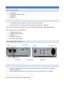
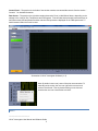
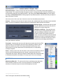
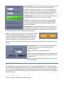
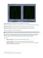
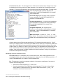
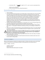
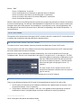
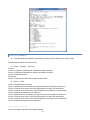
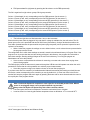
LOI-xF SERIES OPTICAL INTERROGATORS USER MANUAL AND SOFTWARE GUIDE 1.1 CONTENTS Safety ........................................................................................................................................................................2 Laser Safety ..........................................................................................................................................................2 Electrical Safety ....................................................................................................................................................2 Getting Started..........................................................................................................................................................3 What's in the Box ..................................................................................................................................................3 What Else is Needed.............................................................................................................................................3 Front and Back Panels ..........................................................................................................................................3 Installation sequence ............................................................................................................................................3 Software ....................................................................................................................................................................4 Installing the Software ...........................................................................................................................................4 LOI-2F Software ....................................................................................................................................................4 User Interface ....................................................................................................................................................4 Menu ..................................................................................................................................................................5 Controls .............................................................................................................................................................6 FBG Spectra Tab...............................................................................................................................................7 config.ini File......................................................................................................................................................8 Taking Measurements ........................................................................................................................................10 Data File Formats................................................................................................................................................10 LOI-4F software ..................................................................................................................................................11 Installing and Using the Software ....................................................................................................................11 Config.ini file ....................................................................................................................................................11 Data File Formats ............................................................................................................................................12 Troubleshooting ......................................................................................................................................................13 Maintenance and Storage ......................................................................................................................................13 Lenterra Optical Sensor Interrogator ......................................................................................................................14 Specifications, LOI-2F and LOI-4F: ....................................................................................................................14 SAFETY LASER SAFETY The LOI-xF series interrogators are IEC 60825-1 Class 1 laser products, they are intrinsically safe and do not pose a health hazard either to the skin or eyes. Wavelength Laser radiation ~1560 nm Power < 10 mW ELECTRICAL SAFETY There are no user-serviceable parts inside an LOI interrogator and the instrument should not be opened by the operator. If you are experiencing problems, please contact Lenterra Inc. for assistance. _______________________ LOI-xF Interrogator User Manual and Software Guide 2 GETTING STARTED WHAT'S IN THE BOX An interrogator USB type A to USB type B cable A power cable A DVD disk WHAT ELSE IS NEEDED A compatible Lenterra`s RealShear™ or Drag Force Flow (DFF) sensor * A Microsoft Windows PC (Windows XP, Windows Vista, and Windows 7 supported) * LOI-xF series interrogator can also be used to interrogate third party Fiber Bragg Grating based sensors. Recommended minimum PC Specifications: 1 available USB 2.0 Port 2.0 GHz processor or better 2 GB RAM 500 MB free disk space 1366x768 screen resolution FRONT AND BACK PANELS Power indicator Channel 1 Channel 2 USB Port Power entry module Gain adjustments Duplex LC Optical Receptacles Front view LOI-4F shown Back view INSTALLATION SEQUENCE Using the provided DVD, Install the interrogator software (specific instructions are in the following section of this manual). Plug the supplied power cable into the power entry module on the rear panel of the instrument. _______________________ LOI-xF Interrogator User Manual and Software Guide 3 Plug the supplied USB cable into both the instrument and the PC. Power on the unit with the rear-mounted power switch. The blue front panel power indicator will light up. Note: The data acquisition (DAQ) circuitry inside the instrument is powered through the USB bus and will operate even when the unit is powered off. Ensure that the unit is powered on to achieve proper measurements. Connect the RealShear™ or DFF sensor to the interrogator: insert the Duplex LC Optical Plug (on the sensor cable) to the Duplex LC Optical Receptacle of the interrogator, slide the protective collar/cap onto the receptacle and rotate clockwise to lock into position. (Note: The connector is keyed for proper orientation, do not force the plug into the receptacle). Start the software. SOFTWARE The software is developed using NI LabVIEW programming language and requires the LabVIEW Runtime Engine (included in the installation disk) or a pre-existing LabVIEW installation. INSTALLING THE SOFTWARE There are Full Installer and Application-Only Installer available on the disk. The software can also be downloaded from www.lenterra.com/downloads. The Full Installer installs the measurement module and all required National Instruments software. The Application-Only installer is a smaller file that can be used to upgrade any version that was installed previously using a Full Installer. To install the software: Unzip the installer into a temporary directory. Run setup.exe. Follow the on screen instructions. It is recommended to keep the default settings. Restart computer when prompted. At this instant the interrogator should be connected to the USB port on the PC. After restarting, a dialogue will appear to import the hardware configuration from the configData.nce file located in the directory the software was installed into. Click Next and accept defaults in the series of screens that appear afterwards. Note: It is possible to skip the last step by pressing Cancel if the controller is not plugged in or unavailable at the time of installation. The hardware configuration can be imported later through National Instruments Measurement and Automation Explorer under File->Import. An example of the location of the file is 'Program Files\Lenterra\LOI_v1.3\configData.nce'. LOI-2F SOFTWARE USER INTERFACE The software window is divided into three main sections: Menu – The functions of the menu items are described in the section “Menu” below. _______________________ LOI-xF Interrogator User Manual and Software Guide 4 Control Panel – The panel on the left side of the window contains user-accessible controls. See the section “ Controls” for detailed information. Data Screen – The panel on the right side contains three tabs: Force (or Wall Shear Stress, depending on the settings in the config.ini file), Temperature and FBG spectra. First two tabs show plots with measured force (or wall shear stress) and temperature and the real-time FBG spectra are displayed on the FBG spectra tab. To switch between tabs click on tab`s name. Screenshot of LOI-xF Interrogator Software (v1.3) Note: By default x-axes and y-axes of the plots are autoscaled. To manually set the scales, the user can right-click on an axis and uncheck “AutoScale.” Then by double-clicking on the tick mark numbers the user can enter desired axis limits. MENU _______________________ LOI-xF Interrogator User Manual and Software Guide 5 Start measurement – Clicking on this menu item will initiate force (or wall shear stress) and temperature measurements. The measurement data will appear on plots in corresponding tabs. Only last 2,500 data points are dynamically displayed during data acquisition. After being clicked Start measurement menu item caption will change to Stop measurement. Clicking it again will stop data acquisition, and after short delay all acquired data will be shown on plots. Note: the function of this menu item is identical to that of the Start Measurement button. Analysis – Clicking on this menu item will open submenu with available data filters and analysis tools described below. This menu is disabled by default and becomes enabled when data acquisition has finished. Moving average – Selecting this menu item will bring up additional controls on the left panel for applying the moving average filter. Calibration coefficient – Choosing this menu item will bring up a dialog window with a cell in which the calibration coefficient of the sensor should be entered. After pressing the Save button, the entered coefficient is saved and data displayed on the force (or wall shear stress) vs. time plot are recalculated. Pressing the Cancel button will close the dialog window without saving the calibration coefficient. Find peaks – Selecting this menu item will initiate the automatic search for the FBG spectral peaks. The wavelength of the laser will be adjusted by software until the peaks are located in the center of the laser wavelength scanning range. If the software does not find the characteristic FBG spectral peaks, a corresponding message will appear. Finish – Clicking on this menu item will cause a clean exit from the software, and will write the various software parameters (for example, measurement rate) to the configuration file config.ini. When the program is started again this configuration data is accessed and entered automatically, so re-entry by the user is not necessary. CONTROLS Measurement Rate, S/s – The rate at which force or wall shear stress data points will be recorded. Choose one of the 12 pre-set values from 0.25 Samples per seconds (15 measurements per minute) to 500 Samples per seconds. _______________________ LOI-xF Interrogator User Manual and Software Guide 6 Laser wavelength – the indicator displays the central wavelength of the scan range. The software will initially show the laser wavelength suggested for particular interrogator. The value can be adjusted if it is required for the measurement (see section Taking measurement for details). If entered value is outside of the available range for particular controller it will be rounded to the nearest wavelength range limit. Start Measurement – the function of this button is identical to that of the Start Measurement menu item (see the description above). Save Data – Pressing this control will bring up the Save Data dialog which will allow for saving the acquired data into a tab-separated file. This button is disabled by default and becomes enabled when data acquisition has started. Clear Data Plot – This button clears the Force and Temperature plots and deletes the measured data from the memory. The button becomes enabled when the measurement stopped. This function is also done automatically when the Start measurement button is pressed. Finish – Pressing this button will cause a clean exit from the software, and will write measurement parameters (e.g., measurement rate, calibration coefficient) to the configuration file config.ini. When the program is started again this configuration data is accessed and entered automatically, so re-entry by the user is not necessary When the submenu Moving average is selected (from the Analysis menu) additional controls will appear on the left panel: Moving average – When the check-box is selected the moving average filter is applied to the acquired data and result is displayed on the plots. Period – Parameter of the moving average filter. Save – Pressing this will bring up the Save Data dialog which will save the acquired data with applied moving average filter into a tab-delimited file. Close – Pressing this button will hide the controls relevant to the moving average filter. FBG SPECTRA TAB LOI-2F simultaneously interrogates two (and LOI-4F four) fiber Bragg gratings (FBGs). The reflection spectra from each FBG are displayed in real time in this tab and could be memorized selectively. This window allows for real-time control of the spectra positions on the wavelength scale and it is intended to alert the user when the laser wavelength needs to be adjusted (this operation is required when the spectra shift away from the displayed wavelength range). _______________________ LOI-xF Interrogator User Manual and Software Guide 7 Real time spectra plot – Spectra acquired by the interrogator shown in real time. Memorize – Pressing this button copies most recent spectrum from each channel to the Memorized spectra plot. Memorized spectra plot – Displays spectra that were recorded by pressing the Memorize button. Save –Brings up the Save Data dialog which saves the memorized spectra into a tab-delimited file. Clear – This button clears the memorized spectra chart. CONFIG.INI FILE Config.ini is a file stores parameters required for interrogator operation. When the software starts it reads these parameters from the file, and the updated parameters (if any) are written back in this file when the software is exiting. Config.ini is in text format and can be edited in any text editor, for example in Notepad. Main section: Measurement Rate, Hz – The rate at which data points will be recorded. Laser wavelength, nm – The central wavelength of the laser wavelength scan range. Calibration coefficient – Calibration coefficient of the sensor. The units are N/nm if force is measured, or Pa/nm if wall shear stress is measured. _______________________ LOI-xF Interrogator User Manual and Software Guide 8 LD central current, mA – The wavelength of the LOI-2F laser diode (LD) can be changed in two ways: by changing the current through the LD (faster approach) or by changing the LD temperature (slower approach). To record an FBG spectrum, the LD electrical current is periodically varied. The mean value of this saw-shaped signal is saved in this line of the config.ini file. IT IS NOT RECOMMENDED TO CHANGE THIS PARAMETER. LD current range, mA – The range of the LD electrical current modulation. IT IS NOT RECOMMENDED TO CHANGE THIS PARAMETER. LD lowest temperature, C – Low limit for the temperature of the laser diode, which defines the shortest wavelength. IT IS NOT RECOMMENDED TO CHANGE THIS PARAMETER. LD highest temperature, C – High limit for the temperature of the laser diode, which defines the longest wavelength. IT IS NOT RECOMMENDED TO CHANGE THIS PARAMETER. What is measured? – Choices are “Force” or “Wall Shear Stress”. The axis titles, saved data format, and other related outputs are adjusted according to this parameter. DAQ card section: Channel names of the NI DAQ card are specified here. The first part of the name looks like “DevN”, where N is an integer number. It is the name of the DAQ card as it seen by the computer. By default, the name is Dev1, but if National Instruments DAQ cards were used before with the computer, the number could be higher. For example, it is Dev12 in the figure above. The appropriate DAQ card number can be found in the NI Measurement and Automation Explorer (NI MAX), which is a part of the Full Installer package. If the device number in NI MAX is different from what is specified in config.ini file, the name in the file should be adjusted accordingly. Wavelength conversion coefficients section: A0...A2, B1, C0...C11 – Parameters used to convert laser current, laser diode temperature to laser wavelength and back, and to determine the temperature of the sensor from the FBG peak positions. . IT IS NOT RECOMMENDED TO CHANGE THESE PARAMETERS B0 – This parameter is used for temperature calibration. If temperature recalibration of the sensor is required, do the following steps: o o Measure the ambient temperature, T, of the sensor. Determine the positions of the FBG peaks at this temperature. To do that run the software, acquire data for a short period of time, and save the data. Peaks centers, and, are recorded in the columns 3 and 4 of the file. _______________________ LOI-xF Interrogator User Manual and Software Guide 9 B0 T 1 2 B1 , where T is in oC, and are in nm, and value for B1 is o Use formula: o taken from the config.ini file Enter the new value of B0 into config.ini file and save it. 2 TAKING MEASUREMENTS Start the software Click on the FBG spectra tab and make sure that FBG peaks are approximately at the center of the Real time spectra plot. The Force/Wall Shear Stress and temperature measurements are only valid if the maxima of the FBG spectra are inside the total wavelength range as displayed on the Real time spectra plot. If this is not the case, bring the peaks to the center of the plot. It is possible to center peaks by clicking on the Find peaks menu item. The interrogator will automatically search for the peaks and position them in the center of the plot as in the figure on page 8. One can also search for peaks manually by entering a value for the central laser wavelength on the control panel of the GUI. Manual adjustment can be done either before or after the measurement started, while automatic search is only available before the measurement started. If the tops of the peak are flat or peak amplitude is comparable to the noise level, adjust the height of the peaks with gain adjustment knobs located on the back panel of the interrogator. Make sure the calibration coefficient has the same value as specified in the calibration sheet supplied with a sensor. You may adjust the Calibration coefficient by clicking on the Calibration coefficient menu item. When you are ready to start measurements, press the Start Measurement button. The acquired data will be shown on the plots of the Force (or Wall Shear Stress) and Temperature tabs. Only the latest 2,000 data points are displayed. The erroneous results will be recorded if the FBG peak maxima are not visible on the Real time spectra plot. To restore proper measurements the wavelength should be adjusted MANUALLY using the Laser wavelength control on the left panel. When enough data are recorded press the Stop Measurement button. After a short delay, all recorded data will be displayed on the plots. To save the acquired data click on the Save Data button and choose the location and the name of the file in the Save As dialog window. DATA FILE FORMATS When the Save Data button is pressed, the program prompts for a filename and location to save acquired data. These files are plain text files with settings information and data presented in tab delimited columns. Section “Settings”(two lines): Calibration coefficient Measurement rate Date and time when data acquisition was started _______________________ LOI-xF Interrogator User Manual and Software Guide 10 Section “Data” Column 1: Elapsed time, in seconds Column 2: Measured force (in Newtons) or wall shear stress (in Pascals) Column 3: Position of the center of the first FBG peak, in nanometers Column 4: Position of the center of the second FBG peak, in nanometers Column 5: Measured temperature. When the Save button on the FBG spectra tab is pressed, the program also prompts for a filename and location to save memorized spectra. The data in the tab-separated file is organized in four column groups containing the information about pair of FBG spectra. The wavelength (in nm) and power (in arb. units) corresponding to the first FBG spectrum are saved in columns #1 and 2, and those corresponding to the second FBG spectrum – in columns #3 and 4. LOI-4F SOFTWARE The operation of the optical sensor interrogator LOI-4F is similar to that of the model LOI-2F. Certain differences in software and configuration and output data file are described below. INSTALLING AND USING THE SOFTWARE To install the LOI-4F control software, follow the procedure described above for the LOI-2F model. The main sections of the GUI of the software for the LOI-4F are identical to that for the LOI-2F model and menu and control buttons have the same functionality. Since the LOI-4F can be used with two sensors simultaneously, two curves are plotted on the Force and Temperature tabs. The blue curve corresponds to the channel 1, the green curve – to the channel 2. The FBG spectra tab shows four (two pairs) of FBG spectra on the same plot. FBG spectra shown with dark blue and light blue curves correspond to channel 1, and FBG spectra shown with dark green and light green curves – to channel 2. The menu for the LOI-4F is similar to that for LOI-2F except for the Calibration coefficient menu item (see the figure on the left) Measurements are taken the same way as that described above for the LOI-2F software. CONFIG.INI FILE There are two differences between LOI-2F config.ini file (described above) and LOI-4F config.ini file: 1. LOI-4F config.ini file has two lines for calibration coefficients in the [Main] section) for sensors 1 and 2 connected to channels 1 and 2, respectively. 2. The B0 and B1 coefficient for sensors 1 and 2 are in the separate sections [wavelength conversion coefficients for sensor 1] and [wavelength conversion coefficients for sensor 2] respectively. _______________________ LOI-xF Interrogator User Manual and Software Guide 11 DATA FILE FORMATS Force/wall shear stress data file (originates by pressing the Save button on the control panel) The following information is saved in the file: Section “Settings” (two lines): First line: Column 1: Calibration coefficients for sensors connected to channel 1 Column 2: Calibration coefficients for sensors connected to channel 2 Column 3: Measurement rate Second line: Column 1: Date and time when data acquisition was started Section “Data” Column 1: Elapsed time, in seconds Column 2: Measured force (in Newtons) or wall shear stress (in Pascals) from Channel 1 Column 3: Position of the center of the first FBG peak from Channel 1(in nanometers) Column 4: Position of the center of the second FBG peak from Channel 1 (in nanometers) Column 5: Measured temperature from Channel 1. Column 6: Measured force (in Newtons) or wall shear stress (in Pascals) from Channel 2 Column 7: Position of the center of the first FBG peak from Channel 2(in nanometers) Column 8: Position of the center of the second FBG peak from Channel 2 (in nanometers) Column 9: Measured temperature from Channel 2. _______________________ LOI-xF Interrogator User Manual and Software Guide 12 FBG spectra data file (originates by pressing the Save button on the FBG spectra tab) The file is organized in eight column groups. Each group contains: Column 1: Wavelength (in nm) corresponding to the first FBG spectrum (for the sensor 1) Column 2: Power (in arb. units) corresponding to the first FBG spectrum (for the sensor 1) Column 3: Wavelength (in nm) corresponding to the second FBG spectrum (for the sensor 1) Column 4: Power (in arb. units) corresponding to the second FBG spectrum (for the sensor 1) Column 5: Wavelength (in nm) corresponding to the first FBG spectrum (for the sensor 2) Column 6: Power (in arb. units) corresponding to the first FBG spectrum (for the sensor 2) Column 7: Wavelength (in nm) corresponding to the second FBG spectrum (for the sensor 2) Column 8: Power (in arb. units) corresponding to the second FBG spectrum (for the sensor 2) TROUBLESHOOTING The indicator light does not illuminate when I turn on the instrument. Ensure that the power cable is plugged in fully and that AC voltage is available from the wall socket. The AC power input on the unit is protected with two 3A 250V fuses (5mmx20mm). Using a flat-head screwdriver the fuse holder (located between the power switch and power plug receptacle) can be opened to inspect fuse and replace it as necessary. When I restart the program the settings are set to default values, not the values that were present before the program was last closed. The configuration file in which these settings are stored is saved in the software directory in Program Files. If the program is run by a user that does not have writing privileges in this directory, the program will not be able to save these settings. Granting writing privileges to the user for this directory, or running the program as Administrator can solve this problem. I have a sensor connected but the software is measuring a constant value even when varying shear stress is being applied. The DAQ circuitry inside the instrument is powered through the USB bus and will operate even when the unit is powered off. Ensure that the unit is powered on to achieve proper measurements. I have the program running but no data are shown on the real time spectra plot. If you have more than one controller (or installed another National Instruments DAQ cards) you should choose the Device number corresponding to the controller you use (by default it is 1). Enter new value in the Device number field, stop the program and start it again by pressing the button with an arrow located under the menu in the top left part of the program window. MAINTENANCE AND STORAGE Make sure that the Duplex LC receptacle is never open for an extended period of time. When a sensor is not plugged, always cover receptacle with the cup provided. Always clean the Duplex LC Optical Plug with a fiber connector cleaner. The interrogator should not be subjected to excessive mechanical force or vibration. It can be stored in a clean dry place where temperature does not fall below -10oC or exceed 50oC. _______________________ LOI-xF Interrogator User Manual and Software Guide 13 LENTERRA OPTICAL SENSOR INTERROGATOR Lenterra Optical Sensor Interrogator (LOI) is a compact, robust, fast measurement unit designed for the high resolution interrogation of optical sensors (Fiber Bragg Grating or Whispering Gallery Mode sensors) in laboratory or industrial environments. LOI utilizes fast, low noise Distributed Feedback diode laser with narrow linewidth for full spectrum scanning. Adjustable photodiode gains allow for measurement of returned light intensity in a wide dynamic range. LOI is controlled by any standard PC through USB interface. The unit can be used with third party FBG or WGM sensors as well as with Lenterra’s RealShear™ and DFF sensors for measurements of such parameters as wall shear stress, drag force, temperature, strain, viscosity and others. SPECIFICATIONS, LOI-2F AND LOI-4F: LOI-2F LOI-4F MECHANICAL, ENVIRONMENTAL, ELECTRICAL PROPERTIES: Length Width Height Weight Voltage requirements Operating temperature Storage temperature 40 cm (15.5") 30 cm (11.7") 10.5 cm (4.2") 4.7 kg (10.4 lbs) 100‐240 VAC @ 47‐63 Hz From 0°C to 40 °C From ‐10 °C to 50 °C OPTICAL PROPERTIES: Light source Central wavelength Linewidth, FWHM Scan range: via laser temperature1 via laser current1 Scan rate: via laser temperature1 via laser current1 Scan frequency (via laser current)2 Wavelength increment1 at 0.25 Hz at 10 Hz at 100 Hz at 500 Hz FBG spectrum tracking repeatability3 at 0.25 Hz at 10 Hz at 100 Hz at 500 Hz Number of optical channels Connector Photodiode amplifier gain DFB diode laser 1300‐1320 nm, 1540‐1560 nm <10 MHz 3.7 nm 1.3 nm 0.1 nm/s from 0.33 nm/s to 650 nm/s from 0.25 Hz to 500 Hz 1.1 pm 1.1 pm 1.4 pm 7.2 pm 0.22 pm 0.17 pm 0.09 pm 0.31 pm 4 Two Duplex LC/PC 1.1 pm 1.1 pm 0.9 pm 4.3 pm 0.22 pm 0.17 pm 0.06 pm 0.19 pm 2 Duplex LC/PC 105, 106, 107 V/A DATA PROCESSING CAPABILITIES: Interface Software type Software capabilities USB LabVIEW based data acquisition and control software Spectra recording, spectra averaging, spectra tracking, differential spectrum (between channels 1 and 2) tracking, data logger, instrument control ___________________________________________________________________________________________________________________________________________________________________________ 1 Typical, actual values vary Custom orders for frequencies above 500 Hz 3 One sigma Specifications are subject to change without notice 2 Lenterra, Inc. • www.lenterra.com • (973) 623-0755 • [email protected]