1
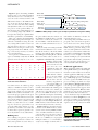
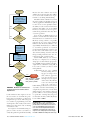
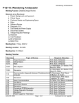
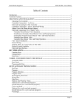
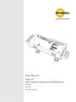
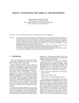
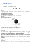
INSTRUMENTS
Tune and test
DDR MEMORY
M
odern electronic devices rely on stable DDR
(double data rate) memory for fast, reliable operation. A shortened time to market, however,
often limits the amount of product testing that
you can perform. Microprocessor-based products released with unstable memory may experience only intermittent failures, but even those can lead to a costly recall.
To minimize that risk, you can follow a comprehensive
memory tuning and testing process that you can verify
with an oscilloscope or logic analyzer.
Tuning is part of configuring a computer system’s
DDR memory. Device-specific tuning will match a
DDR memory device’s timing parameters with the
configuration registers in the DDR memory controller’s CPU. Data sheets for DDR devices specify the timing required for proper operation, listed as fractions of a
second.You must convert these timing parameters to clock
cycles before you can program them into a memory controller. For this conversion, you should write some high-level
DDR memory configuration software that will accept the
standard timing data from a data sheet and convert it into processor clocks for low-level DDR memory drivers.
The next step of the tuning process will vary depending on
your product’s CPU. Many CPUs let the user tune DDR
DOUBLE DATA RATE MEMORY POSES A TRADEOFF
BETWEEN PERFORMANCE AND STABILITY.
memory parameters such as signal termination and read/write
delays that may be specific to a particular board layout. The
user manual for a DDR memory controller will specify any
tuning capability that it provides.
BY ANDREW FISH, KOZIO
Read/write delays
When included as part of the DDR memory controller,
modified read delays or write delays can lead to the most
stable system. A product may have several read/write delay
values for which the DDR memory device will work—a
window of operability. You should test those delay windows
under a range of operating conditions, such as varying temperatures, to find the settings that will optimize DDR mem(continued)
ory reliability.
TEST & MEASUREMENT WORLD www.tmworld.com
DEC. 2008/JAN. 2009
45
INSTRUMENTS
Figure 1 depicts the timing of DDR
memory write cycles with and without
delays. You may need to add delays because the strobe and data transfer will
shift in time relative to the DDR memory clock (not shown in Figure 1). In
some cases, the read/write delay tuning
and adjustment will occur every time a
user powers on the product. Many designs, however, rely on this tuning process
to occur during design only, with the released product using the optimal values
that balance performance and reliability.
After you complete the initial tuning,
you should put the product through several levels of validation testing. In some
cases, testing will reveal the need for additional tuning. The key to effective
DDR memory testing is to make your
tests progressively more difficult, covering connectivity, memory retention,
stress, and performance.
A best practice in DDR memory design is to manually verify that the PCB
(printed-circuit board) traces are con-
Write data
strobe clock
Data bus
Write data clock delay tuning value
Write data
strobe clock
with delay
Write data clock delay tuning value
Data bus
with delay
FIGURE 1. Adding delay to a write cycle can improve performance and system stability.
the given address. First, the software sets
the LSB (least-significant bit) to 1 and all
other bits to 0. Next, the software sets
the next LSB to 1 and all other bits to 0;
and so on, until each bit has been set to 1
(Figure 2).
After you verify connectivity, you should
run functional validation tests to ensure
that all the memory cells in the DDR
memory can retain the values written to
them. Filling and verifying all the cells with
their own address values as data can accomplish this task. Additionally, you should
fill all the cells and verify
that all the memory cells
MSB
LSB
can store both ones and
...
0
0
0
0
0
0
0
1
zeros. Use the one’s
...
0
0
0
0
0
0
1
0
complement of the cells’
...
addresses to run this test.
0
0
0
0
0
1
0
0
S eve r a l a d va n c e d
..
CPUs
include software
.
that perfor ms DDR
...
1
0
0
0
0
0
0
0
memor y stress tests,
which ensure that the
FIGURE 2. A walking-ones data pattern ensures that no
memory can perform at
shorts exist across data lines.
your system’s full speed.
nected.You can use an oscilloscope, logic Such processors can simulate an applicaanalyzer, or multimeter for this connec- tion-like environment. By running your
tion test. Once you complete this initial functional tests with cache enabled, you
design check, software tests can verify the will also force data bursts between the
DDR memory address and data line con- processor and DDR memory as cache
nections for proper operation at the speed lines get flushed and replaced. Running
of the processor. An address bus test writes DMA (direct-memory access) loop tests
a base pattern and then a test pattern to all while also receiving Ethernet packets via
power-of-two offsets (0001h, 0002h, interrupts can cause multiple simultaneous
0004h, etc.). Data bus tests use a “walk- DDR memory reads and writes that will
ing-ones-and-zeros” pattern that tests stress the memory and ensure coherency.
across the width of the data bus on a sinFigure 3 illustrates the block-level ingle memory word. These tests verify that teraction of the DDR memory with a
no shorts exist to power or ground or be- system’s cache memory, DMA, and Ethtween any data lines or any address lines.
ernet controllers. Each line between the
components represents data transfers
Walking ones
from one logic component to the other.
For a walking-ones pattern, your soft- In the case of DMA, you can program
ware, whether purchased or written in- multiple transfers to occur simultanehouse, must perform successive writes to ously across multiple channels. The ac46 DEC. 2008/JAN. 2009
tual number of channels is a feature of a
particular microprocessor.
Knowing that your DDR memory is
properly connected and won’t produce
errors under stress isn’t always enough.
You must also measure how well the
DDR memory performs. Using a software test with optimized read and write
routines, you can determine whether the
performance and throughput of the DDR
memory are fast enough to ensure that
software running in your system will run
properly.You must measure performance
early in a product’s development to resolve any bottlenecks in the data path.
Dedicated applications
When developing software for tuning and
testing DDR memory, you should implement the needed routines in a dedicated
software application. Although you could
develop JTAG tests for tuning and testing—a fairly simple process—you wouldn’t
be able to operate the DDR memory at a
processor’s full speed, which is a major
testing limitation. Building DDR memory
tests on top of an application is also a
tempting option, but this approach for
memory testing makes it difficult to find a
problem’s root cause because of the many
layers of software that test routines use.
You should develop modular DDR
memory test software (Figure 4) so you
can reuse test routines across departments
throughout your organization. Design
engineers can use the software for initial
DMA
Cache
DDR
Ethernet
FIGURE 3. During a test, DDR memory
must interact with cache memory, DMA,
and Ethernet controllers.
www.tmworld.com TEST & MEASUREMENT WORLD
Start
Because the same software was used to
validate the product’s design, there will be
no need to rerun extensive stress or perProgram controller
formance tests during manufacturing.
with transfer
Modular software will also let you run
parameters of chain
the same routines in a POST (power-on
m on channel n
self-test) application. If POST is required,
it often needs to run quickly but have
More
the ability to warn end users if a memory
Yes
transfers
problem exists. Thus, you can use DDR
in chain?
memory test routines to uncover potential memory problems before they affect
No
a system’s operation.
You can also use DDR memory test
More
Yes
software on units that have failed in the
channels
field and have been returned for service.
to program?
Memory-testing software can quickly
pinpoint the root cause of the problem.
No
Software that effectively validates a design initially should always be sufficient
Initialize
transfer ranges
to deter mine problems on returned
and start
products. Field application engineers can
all channels
use the same set of software tests to validate memory during customer visits and
find potential problems before the cusCheck
tomer knows that a problem exists.
error
Stable DDR memory can often be
conditions
the key to a company’s success. Using a
design process that includes proper tuning of DDR memory, followed by thorAll
No
channels
ough memory validation testing will, at
complete?
least, assure you that you have a stable
main platform.
Additionally, if you create a DDR
Yes
memory tuning and testing process using a modYes
Detected
ular software approach,
Fail
error?
you can reuse the process
DMA_INTERRUPT_ERROR
throughout your organiDMA_TIMEOUT_ERROR
zation. Not only will the
No
DMA_VERIFY_ERROR
reuse save money, it will
Pass
help your company to
build reliable products and correct memory faults—whether found during deFIGURE 4. Modular test software lets
engineers share test routines across
velopment, in production, or in the field.
departments.
Stable memory can’t guarantee that your
product will be a success, but neglecting
board verification. Test engineers can use to spend time ensuring that your prodthe test routines to determine if a prob- uct has stable memory will nearly always
lem is related to hardware or software by lead to failure. T&MW
using known-good tests. A known-good
test contains no programming errors that Andrew Fish is a senior contributor to
would produce false results, such as iden- Kozio’s library-based functional tests. He
tifying errors that don’t exist or missing joined Kozio in 2004 and has more than 11
years of embedded programming experierrors that do exist.
ence. Fish has developed advanced test
Test engineers and manufacturing en- capabilities and support for numerous migineers can also use the test routines to croprocessors and peripheral technologies.
verify data paths and general functionality. He holds a BSEE from Marquette University.
TEST & MEASUREMENT WORLD www.tmworld.com
DEC. 2008/JAN. 2009
47