1
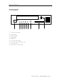
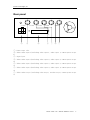
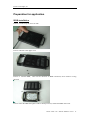
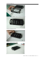
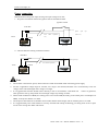
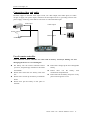
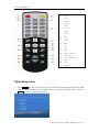
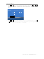
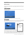
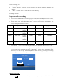
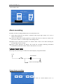
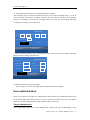
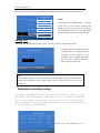
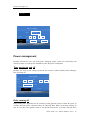
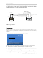
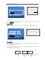
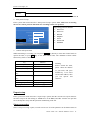
Kocchi’s Technologies, Inc. Mobile DVR
User manual
Applicable for MDR1011, MDR1021, MDR1041
Thanks for using our products. Please read following user manual, so that you can use and protect
your device correctly. Please put this user manual in a safe and convenient place when read it over,
for the convenience of reference in the future.
Kocchi’s Technologies Inc
Add: 12/F Xinhua Insurance Building Mingtian Road, Futian District, 518048 Shenzhen, China,
Tel:+86-755-8340-5307
Fax:+86-755-8340-6099
Website:www.kocchis.com
Mobile DVR User’s Manual MDR10x1 Series
1
Kocchi’s Technologies, Inc. Warning
This device have no feature of waterproof, In order to prevent from accident of fire or electric shock,
please don’t ever put any container full of water (laver or vase) on the neighborhood or expose it
under the water drop, splash and moisture.
CAUTION
RISK OF ELECTRIC SHOCK
DO NOT OPEN
The lightning flash with arrowhead
symbol,within an equilateral triangle is
intended to alert the user to the presence
of uninsulated “dangerous voltage”
within the products enclosure that may
be of sufficient magnitude to constitute a
risk of electric shock to person.
The exclamation point within an
CAUTIO
TO PREVENT THE RISK OF ELECTRIC
SHOCK.. DO NOT REMOVE COVER (OR
BACK
).
.NO
USER-SERVICEABLE
PARTS INSIDE. REFER SERVICING TO
QUALIFIED SERVICE
PERSONNE
equilateral triangle is intended to alert
the user to the presence of important
operating and maintenance (servicing)
instructions
in
the
literature
accompanying the appliance
Accessory list
Item
Description
Quantity
1
Video Recorder
1 PCS
2
Video and Audio Input cable
4 PCS
3
Video and Audio Output cable
1 PCS
4
Integration cable
1 PCS
5
Remote controller
1 PCS
6
Keys
2 PCS
7
Fixing rack
2 PCS
8
Fuse box
1 PCS
9
5 Amp fuse
2 PCS
10
Screw for installation of recorder
4 PCS
11
Screw for HDD fixing
4 PCS
12
Power Cable with Ignition
1 PCS
Mobile DVR User’s Manual MDR10x1 Series
2
Kocchi’s Technologies, Inc. Feature of function .................................................................................................................... 5
Front panel ................................................................................................................................ 7
Rear panel ................................................................................................................................. 8
Connection ................................................................................................................................ 9
Preparation for application ...................................................................................................... 12
HDD installation ............................................................................................................. 12
Power connecting ............................................................................................................ 14
Connecting video and audio ............................................................................................ 15
Use of remote controller.................................................................................................. 15
Operating menu ....................................................................................................................... 16
HDD operation ........................................................................................................................ 18
Check-up HDD status ..................................................................................................... 18
HDD formatting .............................................................................................................. 18
Preparation for recording ................................................................................................ 19
Start recording ................................................................................................................. 19
Stop recording ................................................................................................................. 20
Play back ................................................................................................................................. 20
Manually selecting file to play ........................................................................................ 20
Number plate setup ......................................................................................................... 22
Speed setup ..................................................................................................................... 22
Marching status sensor setup .......................................................................................... 23
Alarm recording ...................................................................................................................... 24
Connect alarm signal ....................................................................................................... 24
Setup alarm recording ..................................................................................................... 24
Alarm linkage setup ........................................................................................................ 25
Defend and startup alarm prerecording ........................................................................... 26
Motion detecting setup .................................................................................................... 26
User administration ................................................................................................................. 27
Setup administrator ......................................................................................................... 27
Adding user ..................................................................................................................... 28
Schedule recording setup ........................................................................................................ 28
Power management ................................................................................................................. 29
Time turning on and off................................................................................................... 29
Delay turning off ............................................................................................................. 29
Other operation ....................................................................................................................... 30
Program copy .................................................................................................................. 30
System time ..................................................................................................................... 31
PTZ control ..................................................................................................................... 31
Export setup .................................................................................................................... 32
Setup recovering ............................................................................................................. 32
system log ....................................................................................................................... 33
System information ......................................................................................................... 33
Specification ........................................................................................................................... 34
Addenda 1 ............................................................................................................................... 35
Mobile DVR User’s Manual MDR10x1 Series
3
Kocchi’s Technologies, Inc. Addenda 2 ............................................................................................................................... 36
Connection of GPS receiver ............................................................................................ 36
Mobile DVR User’s Manual MDR10x1 Series
4
Kocchi’s Technologies, Inc. Feature of function
Video and audio
z
z
z
MPEG2 algorithm for video compression, high resolution, real time recording.
DVD (704x576) image quality for one channel recording, CIF(352x288)for 4 channels
recording.
Support 4 channels video (maximum) and two channels audio real time recording
Power supply
z
z
Support wide range of voltage input, allow DC 8V to 32V input for normal working. So car
with 12V or 24V power supply is applicable
When the power input connects in reverse polarity, the auto-protect function can prevent the
recorder and battery from damage.
The recorder provides each camera with stable 12V DC power, which can send out alarm
when the power output is in short circuit.
Time Scheduled Power On and Off function can save power from the battery.
z
Can turn on and off by car ignition switch, Shut down delay (0~60 minutes adjustable)
z
z
recording function
z Recording mode
z
z
z
z
Continue record
Auto-record while turning on.
Support time schedule recording
Support alarm trigger recording, can set as auto-record while opening the door.
Support motion detection recording
Shock proof design
z
z
Suspending shock proof mode for HDD protection;
High Reliability Removable HDD Rack connector, can make sure of stabilization and avoid
the problem of normal HDD Rack connector by using dot touch connecting mode;
HDD
z
z
z
Removable HDD box supports 2.5 inch notebook HDD;
HDD can be compatible for FAT32 format, Enabling the data in HDD can be read directly by
PC with Microsoft Windows OS;
Multi-backup and auto correction file system can avoid file lose problem due to the 0 track or
file list damage in many case.
Speed and Marching status recording
z
Synchronously display and record the speed and vehicle ID;
6 channels sensor signal input, can synchronously display and record the vehicle status such
as brake, turning left or right, alarm whistling etc.
Mobile DVR User’s Manual MDR10x1 Series
5
Kocchi’s Technologies, Inc. z
z
Over-speed alarm function available;
Reverse signal trigger video switch function available.
Caution
Please read following caution before you use this device. And strictly follow the following
security instruction while operating the device.
1)
2)
3)
4)
5)
6)
7)
8)
Please read over all of the caution
Please hold this caution for reference in the future.
Please notice all of warning information.
Please strictly follow the instruction in the manual while operating
Please never put this device under the place which is easily poured by water.
Clean this device by wiping it with soft and dry cloth
Please don’t have the airiness heat exchange gate closed
Please leave the device far away from hot and high temperature
environment
9) Install the device with the accessory coming with it.
10) Please take care when move this device, make sure of security, avoid being
damaged by dropping from high place.
11) Call for the qualified maintenance man to repair.
Mobile DVR User’s Manual MDR10x1 Series
6
Kocchi’s Technologies, Inc. Front panel
ON
OFF
NET
①
PWR RUN ALM HDD CF
②
③ ④ ⑤
⑥
IR
CF CARD
⑦
⑧
⑨
①:Network Interface
②:Power LED
③:Running LED
④:Alarm LED
⑤:HDD LED
⑥:CF card exist LED
⑦:External IR Controller slot
⑧:CF card slot
⑨:Electronic lock switch
Mobile DVR User’s Manual MDR10x1 Series
7
Kocchi’s Technologies, Inc. Rear panel
J2 CAM2
J1 CAM1
J3 CAM3
J4 CAM4
J5 MON
POWER IN
J6 (SENSOR RS485 RS232 ALARM)
DC 8V-32V
①
①:Power input
②:Video-audio
1)
③:Signal port
④:Video-audio
2)
⑤:Video-audio
3)
⑥:Video-audio
4)
⑦:Video-audio
5)
②
③
④
⑤
⑥
⑦
slot
input 1(including video input 1, audio input 1, camera power output
input 2(including video input 2, audio input 2, camera power output
input 3(including video input 3, audio input 3, camera power output
input 4(including video input 4, audio input 4, camera power output
output (including video output, 2 audio output, camera power output
Mobile DVR User’s Manual MDR10x1 Series
8
Kocchi’s Technologies, Inc. Connection
1、 Power input cable
PIN 4
PIN2
PIN 3
PIN 1
PIN NUM
Color
PIN 6
PIN 5
Description
2
Red
Power anode input (connect to anode of car battery)
4
Yellow
Car ignition signal input(Connect this wire to anode of car battery when don’t
need to control the recorder power through ignition signal)
6
Black
Power cathode input(connect to cathode of car battery)
2、 Video-audio input connection
1) Video-audio input cable
Mark
Description
VIN
Video input
AIN
Audio Input
+12V
Power output anode(DC12V, Maximum 1A)
GND
Power and Signal output cathode
2) Video-audio output connection
Mark
Description
VOUT
Video Output
Mobile DVR User’s Manual MDR10x1 Series
9
Kocchi’s Technologies, Inc. AOUT1
L channel for audio output
AOUT2
R channel for audio output
+12V
Power output anode(12V, Maximum 1A),capable for LCD(Note: The current for
LCD can’t be over 1A)
GND
Power and Signal output cathode
3、 Integration Cable
Junction
Mark
Color
Description
1
R2
Receive (GPS output)
2
R2
RS232 Port2, Send(GPS output)
3
R1
RS232 Port1,Receive(GPS output)
4
R1
RS232 port2,Sent(GPS input)
5
(none)
Grounding
6
(none)
+5V Power output
7
+
Red
RS485 Anode port
8
-
Black
RS485 Cathode port
9
IR
10
O1
Red
Alarm output 1,B pole
11
O1
Red brown
Alarm output 1,A pole
12
O2
Red
Alarm output 2,B pole
13
O2
Red brown
Alarm output 2,A pole
IR Control panel Signal
Mobile DVR User’s Manual MDR10x1 Series 10
Kocchi’s Technologies, Inc. 14
S1-6
Black
1 Sensor Input 1
15
S1-6
Brown
Sensor Input 2
16
S1-6
Red
Sensor Input 3
17
S1-6
Red brown
Sensor Input 4
18
S1-6
Yellow
Sensor Input 5
19
S1-6
Green
6 Sensor Input 6
20
S
Blue
Speed sensor input
21
IR
22
M1-4
Black
Alarm input 1
23
M1-4
Brown
Alarm input 2
24
M1-4
Red
Alarm input 3
25
M1-4
Red brown
Alarm input 4
Operating panel power port
4、 GPS Input Port definition (RS232 port 1)
PIN
Description
2
TXD,Data send out
3
RXD,Data receive
5
GND,Grounding
9
+5V,Power output
5、 GPS output port definition (RS232 port 1)
Junction
Description
2
TXD,Data send out
3
RXD,Data receive
5
GND,Grounding
Mobile DVR User’s Manual MDR10x1 Series
11
Kocchi’s Technologies, Inc. Preparation for application
HDD installation
Process 1: Take away the screw on side
Process 2: Remove the upper cover
Process 3: Connect HDD,
direction
take care the direction of HDD connection, don’t install in wrong
Process 4: Put the HDD through the rubber shock proof mat, and fix the HDD on the mat
Mobile DVR User’s Manual MDR10x1 Series 12
Kocchi’s Technologies, Inc. Process 5: Seal the HDD by upper cover after fix up HDD
Process 6: Install side screws
Process 7: HDD installation finish
Mobile DVR User’s Manual MDR10x1 Series 13
Kocchi’s Technologies, Inc. Power connecting
Mobile DVR use DC power input, the range for input voltage is 8V-32V.
1、The power connection instance for ignition switch controlled recorder
Ignition switch
Fuse box
Power input(Red wire)
Ignition
signal
input
(
Power
Anode
Cathode
cathode
(Yellow wire)
input(Black
wire)
Recorder
Car accumulator
2、24 hours full time running connection instance
Fuse box
Power input
Ignition signal input
Power cathode input (Black)
Anode
Cathode
Car accumulator
Note
1. The recorder consumes DC power, Please notice the anode and cathode while connecting power supply
2. 8V-32V is applicable voltage range for recorder, over range is not allowed, Recorder can’t work normally at too low
voltage, and it will be damaged if the voltage is too high.
3. It is suggested that recorder should connect directly to the car accumulator, it had better not
when generator start-up, the possible shot time high voltage may damage recorder
connect to generator,
4. When finish installation of HDD, the startup power will exceed 60W(According to the actual power consumption of
HDD), so the power shall be over 60W.
5. The all power cable between accumulator and recorder shall be thick enough, and can load the power over 60W
6. It is suggested that power cable shall be covered by wearable and waterproof bushing, preventing short circuit or open
circuit cause of long time shake and friction.
Mobile DVR User’s Manual MDR10x1 Series 14
Kocchi’s Technologies, Inc. Connecting video and audio
Recorder support 4 channels video input at most, one video output; Two audio input, two audio
out put. It supply 12V power output, maximum current output can be 1A, providing cameras with
power supply. Following chart shall be connection of video and audio input.
Video input
Video output
Power output
Audio output
Audio input
Use of remote controller
Note! Incorrect remote controller use will result in battery electrolyte leaking out and
damaging the device or even catching fire
z
z
z
z
Put battery into the remote controller before
you use it, and please pay attention to the anode
and cathode.
Please don’t blend the new battery with used
one.
Please don’t scratch up the battery of different
brand
Please don’t put the battery on hot place or
firework.
z
z
z
Please don’t charge up the non rechargeable
battery
Please don’t use the battery with
membranous desquamation.
Please take out the battery and put it on dry
place when long time no use
Mobile DVR User’s Manual MDR10x1 Series 15
Kocchi’s Technologies, Inc. 1.
2.
3.
4.
5.
6.
7.
8.
9.
10.
11.
12.
13.
14.
15.
16.
17.
18.
19.
20.
21.
Power
Stop
Record
Alarm
Play
No. Key
Audio
Video
Up
Left
Right
Menu
Esc
Ok
Down
Fast Forward
Pause/Step
Fast Backward
OSD
Next
Previous
Operating menu
1、 Press MENU key and enter system menu, If user had set administrator password, he shall
input the password before enter system menu, No password at default status, and press
MENU key to enter system menu directly.
^ Record searching
System setup
Record setup
Time record
Alarm setup
Alarm linkage
v Program copy
Mobile DVR User’s Manual MDR10x1 Series 16
Kocchi’s Technologies, Inc. 2、 Press ▲ or ▼ key to select different menu option, then press MENU or ENTER
key to enter the option. Following chart shall be dialogue box for “system setup”
option.
System setup
Auto-coverer
On
TV system
0
Minute
PAL
Auto-log out
Confirm
Cancel
3、 Press ▲ or ▼ key to select different option in the dialogue box, or press >
or < key select different option in the dialogue box, you can input No. or
character to the option box when it is editable.
Mobile DVR User’s Manual MDR10x1 Series 17
Kocchi’s Technologies, Inc. HDD operation
Recorder use 2.5 inch notebook HDD to store recording data. HDD shall be installed into the
removable HDD rack, Please refer to HDD installing instruction the former chapter of
“installation”
Check-up HDD status
When recorder start-up, you can enter “system information” option in system menu to check if the
system had detected HDD
System information
Edition No.:FEB 28 2006
IDE1 Master device:HDD 250.1 G
IDE1 Slave device:None
IDE Master device:None
IDE2 Slave device:None
IDE3 Master device:None
IDE3 Slave device:None
Showing as above legend, System IDE master device had detected a 250G HDD.
HDD formatting
You should format the HDD in the recorder before use it to record image. Please enter “formatting”
option in main menu to format HDD. The time of formatting shall depend on the HDD capacity,
longer time for larger capacity, it takes more than 3 minute, so please patiently wait.
Format
Disk1
Device
confirm
Cancel
Note
All original files will be
deleted after format!
Please backup the files
before format HDD
ESMPFS file administrating system will be in operation after
finish HDD formatting, this file system is specially designed
for in car environment, Compatible for FAT32 file format,
besides, it has multi-layer file backup and correct function, farthest preventing the recording data
from losing. The system will automatically create following directory in HDD after formatting
z “Recording”directory: Recorder will automatically store the recording data to this directory.
Mobile DVR User’s Manual MDR10x1 Series 18
Kocchi’s Technologies, Inc. z
z
“backup”directory: User can store the recording data which is needed to backup to this
directory.
“Other”directory: User can store other file to this directory.
Recording operation
Preparation for recording
1、 If use a new installed HDD to record image, you should format the HDD first in this recorder;
please refer to formatting instruction in former chapter“Disk operation”
2、 Image quality setup: Enter“Recording setup”menu to setup recording image quality. The
image quality parameter shows below:
Image
quality
Image
resolution
Sound
Video code
flow(Bit/s)
Audio code
flow(Bit/s)
Occupying disk space
Simple
352×258
Couple
channel
1152K
224K
619M/Hour
normal
480×576
Couple
channel
2400K
224K
1180M/Hour
Middling
704×576
Couple
channel
3000K
224K
1450M/Hour
Better
704×576
Couple
channel
4000K
224K
1900 M/Hour
Best
704×576
Couple
channel
6000K
224K
2800 M/Hour
3、 You can setup “auto cover”switch in system setup menu. When set“auto cover”as “On”,
Recorder will delete the earliest recording data in“Recording”directory if residual HDD space
is not enough, but it just deletes the file in “Recording”directory only, and the file in other
direct not; The user can copy the recording data to other directory, preventing the recording
from being covered automatically.
System setup
Auto-cover
On
Auto-log out
0
TV system
PAL
Minute
Confirm
Cancel
Start recording
z
Press REC key to start recording, when recording starts, a small red dot will
Mobile DVR User’s Manual MDR10x1 Series 19
Kocchi’s Technologies, Inc. z
appear on the top left corner of display to show that it is recording
Recorder will automatically pack the recording data as a file per hour.
Stop recording
Press ■ key to stop recording.
Play back
Manually selecting file to play
¾
¾
While recording, every day It will create a directory according to the date of that day, and the
recording data stores in that directory, the name format of file will be “Starting time_Date_Number plate.mpg”, For instance, “160101_060306_BKF645.mpg”means that the
date of that recording file is 6th Mar 2006 and starting time is 16:01:01 and number place is
BKF645.
Press > playing key, then select the recording date, it will list out all of the recording file in
that day.
06-03-06
Back <
160101_060306_BKF645.mpg
164301_060306_BKF645.mpg
¾
Select sort of recorded which need to replay
Program
Program name
160101_060306_BKF645.mpg
Open
Delete
Cancel
¾
¾
Press ■ key to stop playing
Press “Play/pause” key if you want to pause playing while playing.
Mobile DVR User’s Manual MDR10x1 Series 20
Kocchi’s Technologies, Inc. ¾
¾
¾
¾
¾
In pause status, the recorder will play by single frame if press“Play/pause”key again
When press“Page up”or“Page down”, the recorder will play Last/Next file in current
directory.
When press“Play/pause”or“Fast backward”key, recorder will play current file fast forward
or fast backward
Press “Sound channel”key to play one channel of the two channels audio
Press “Image select”key to playback image from one channel.
Play by time
When you want to play the recording data in a certain time, recorder can play it by time searching,
and the precision for searching can reach second class. Enter main menu and select “Image search”
option, then input the time you want to search about in the dialogue box.
Image search
2006
03
/
16
:
06
/
03
:
z
16
z
Confirm
Cancel
z
Recorded clips are arranged by date
and time and stored in “Record”
directory. Press “PLAY” key, you can
find the recorded clips in “Record”
directory and play it.
User can select clips in other
directories to play the MPEG files.
You can play clips when the MDR in
recording status.
If the searching is successful, the file information will be displayed. If no exactly marched file,
MDR will list the nearest file by time.
Search result
Search made
Date:2006-03-06
Time:16:01:02 - 16:19:22
Play
Cancel
Caution
The HDD will enter idle mode
when no operation on HDD over 5
minutes (no play or record). In this
case, when you press “PLAY” key,
the HDD need 3 or 5 second to
spin up, please be patient.
Select “Play”, it will play from the setting time.
Car related information setup
Recorder can display the related car information in the image, such as number plate, speed,
turning or brake etc all kinds of marching status. All those information will be stored
synchronously together with the image, enabling the user to check the related car information
synchronously when playback the image. The display position of car speed shows as following
chart, press OSD key to show or delete the car information.
Mobile DVR User’s Manual MDR10x1 Series 21
Kocchi’s Technologies, Inc. Number plate
BKF645
Speed
43km/h
LRB
Marching status
Number plate setup
Select “Car setup” option in main menu, and input the number to “number plate” column, the
number can be combination of English letter, character, figure and punctuation
Car setup
Way of character input to the column: Continuously
press the No. key till the character you need about
come out, for instance, if you want to input “A” you
can press No. key “2” continuously till “A” come
out, when want to input next character, you shall
press “right” key to move the cursor forward to the
position of next character, then you can input the
next one.
Number plate
Pulse
0
Confirm
/
1
Km
Cancel
Speed setup
1、 Connecting speed sensor
Recorder can read the pulse signal through the signal output from car speed sensor, then calculate
the marching speed. For the car installing with electronic speedometer, it can take the electronic
pulse signal of speed directory from the speedometer; And for the car with mechanized
speedometer, it shall additionally install a Honeywell electronic speed sensor, please refer to the
instruction of installing way in addenda 1
speed sensor
If there is speed signal output from the speedometer, then it can take the output signal directly as
speed signal input to the recorder; if the speedometer can not send out the speed signal, the
recorder shall get the speed signal from the signal input port of speedometer.
Connect to speed sensor input
cable of recorder
Mobile DVR User’s Manual MDR10x1 Series 22
Kocchi’s Technologies, Inc. Connect to speed sensor
input cable of recorder
2、 Speed setup
When having correctly connected the speed sensor to recorder, the recorder shall setup beforehand
the output pulse number per hour generated by marching car, then you can accurately calculate the
speed. Select “car setup” option in main menu, you can input the pulse number directly if it had
been calculated or determined in advance. And you can make a spot test in the car, here shall be
the detailed approach
1) Enter main menu to select “car setup” option, set the “pulse number” as 0 in the column.
2) The number in column will increase while the car running
3) Stop the car after moving 1 Km, then the number in the column will be the accurate pulse
number.
4) Press “confirm” key to finish the setup
5) Exit the main menu and check if the display speed accord with the actual speed.
Marching status sensor setup
Connect marching status signal.
Recorder can connect 6 channels sensor input, the sensor signal cable directly connects to the
appreciate relay output (like brake light relay). Following sketch map shall be connection for
recorder braking signal (effective for high voltage)
+12V/24V
Brake light
Connect to recorder
sensor input cable
1、 Setup marching status
It comes out an external alarm event from inner of recorder while the sensor signal changing, and
the recorder can make some alarm linkage action on the sensor signal according to the setting of
Mobile DVR User’s Manual MDR10x1 Series 23
Kocchi’s Technologies, Inc. “alarm linkage setup”
Sensor signal 1
Alarm recording
Alarm out 1
Video switch
Off
Buzzer
Off
On
Alarm out2
Off
Information
Off
Confirmation
Cancel
Alarm recording
Recorder can start recording with the burst of external alarm event
1) Alarm input: Recorder can connect 4 channels alarm input, high voltage (8 to 32V) is
effective for alarm input.
2) Video loss: When the recording signal lose, recorder will come out “video lose” alarm event.
User can set “buzzer” or “alarm output” alarm linkage action,
3) Motion detect: Recorder can make out “motion detect” alarm event while detecting the
moving image in area coverage.
4) Sensor signal: Recorder can display and record the according indicating information
synchronously when the recorder connects with effective car sensor.
Connect alarm signal
Following is the sketch map for connection of alarm input by using alarm whistle
+12V
Alarm whistle
connect to alarm input cable
Setup alarm recording
Alarm setup
Prerecord
0
:
0
Delay record
0
:
0
Mobile DVR User’s Manual MDR10x1 Series 24
Kocchi’s Technologies, Inc. Detecting
Off
Over-speed
0
km/h
sensitivity
z
z
z
z
z
Detecting sensitivity: It is used to setup the sensitivity of motion detect, there are 9 levels. 1
for lowest level, and 9 for the highest.
Over-speed: for over-speed value setup, it don’t check over-speed if the value is 0
Alarm prerecord: You can setup and record the alarm recording before alarm event burst, the
maximum time for alarm prerecording can be 99minute 59second, you shall press “right” key
to come to defending status first then come to alarm prerecording status.
Alarm delay recording: Alarm delay recording means that the recorder still continue to record
when alarm event disappear, till the setting time pass. And the maximum alarm delay
recording time can be 99minute 59second.
The pre-record, alarm record and delay record pieces will be managed into a whole
completed alarm recording file. If the whole time exceed over 1 hour, the file will be saved
by into several pieces and the maxim file length should be 1 hour.
Alarm disappear
Alarm burst
Prerecord
Alarm record
Delay record
Complete record segment
Alarm linkage setup
Recorder can do 5 types of alarm linkage action.
1) Alarm recording: Recorder can timely record and store the recording data when external
alarm event burst the recording. If there is external alarm event (sensor signal) bursting out,
recorder will start recording immediately and keep recording until the alarm event disappears.
2) Buzzer: Recorder can awake the user by ringing the buzzer when there is external alarm event
bursting out.
3) Alarm output: There are 2 channels alarm output on recorder, which can load maximum
current of 1A.
Alarm output A +12V
Camera
Alarm output B
4) Video switch: Recorder can do “video switch” linkage action according to external alarm
event, this setup is available for 2 or 4 channels recorder, it use backup signal to switch full
screen display of rearview video.
Sensor 1
Full screen display of rearview video
Backup signal
Mobile DVR User’s Manual MDR10x1 Series 25
Kocchi’s Technologies, Inc. 5) Information: Recorder can set 2 characters for car marching information.
Defend and startup alarm prerecording
For alarm linkage, if you set “alarm recording” for the alarm event as “On”, then recorder can start
recording automatically when alarm event occurs. If the “alarm prerecording” time is not 0, user
needs to press “right” key to enter defending status, meanwhile, recorder starts alarm prerecording;
If user want to withdraw defending, he shall press “left” key.
Motion detecting setup
1) Detecting area setup
a) Adding motion detecting area
Motion detecting area setup means that you can set the surveillance zone on any position of
image, 8 zones available totally. The following icon will show on the image when enter the motion
detecting setup.
Top left corner of setup
┏
It will show a “┏” symbol on the screen which is used to confirm the top left corner
coordinate of setup area. There are two steps for motion detecting area setup: Firstly, setup the top
left corner of setup area, you can adjust the position of top left corner by “up” “ down” “left” and
“right” key, when the top left corner is in the right position, press again “ ENTER ” key to confirm;
Secondly, setup the bottom right corner, you can adjust the position of bottom left corner by “up”
“ down” “left” and “right” key, when the bottom right corner is in the right position, press again
“ ENTER ” key to confirm, then the motion detecting area setup for first channel video will be
stored in recorder, and recorder will indicate if you want to enter the second setup zone, Press
“ ENTER ” key to confirm, then you can setup the area for second video by referring to the
procedure of first video.
b) Delete motion detecting area
When you enter the menu of deleting motion detecting area, you will find a yellow column
which is stand for the selected motion detecting zone, as well as the green column which is
unselected one, then press “up” “ down” “left” and “right” key to switch among the detecting
zones, and press ENTER key to delete the selected yellow column, or press ENTER key to
cancel.
Mobile DVR User’s Manual MDR10x1 Series 26
Kocchi’s Technologies, Inc. 2) Setup detecting sensitivity, prerecording and delay recording
You can totally setup 9 levels for detecting sensitivity in the “alarm recording setup”, 1 level for
lowest sensitivity and 9 levels for highest sensitivity, the user shall test and select the appropriate
sensitivity according to actual image and light status, then setup the prerecording and delay
recording time basing on the actual needs
Alarm setup
Prerecor
Delay
: 0
0
:
0
0
record
Detecting sensitivity
联动动作。
1
Cancel
Confirm
3)Select “motion detecting” in the “alarm linkage setup”, and setup “alarm recording” such alarm
linkage action according to actual needs
Motion detecting
Alarm recording
On
Buzzer
Off
Alarm output1
Off
Alarm output 2
Off
Video switch
Off
Information
MD
Confirm
Cancel
4) Defend and startup alarm prerecording
Press “right” key to enter defending status and startup alarm prerecording.
User administration
There are two kinds of recorder user: Administrator and normal user, the administrator has all of
the operating right, and normal user has no right to setup the recorder, but just has the right to
watch or to record and playback the image segment under own director
Setup administrator
Enter system main menu, select “user administration” option, and select “administrator” in the
Mobile DVR User’s Manual MDR10x1 Series 27
Kocchi’s Technologies, Inc. listed user name, then input the original password and new password to setup the user password.
User administration
User name
Note
Administrator
No password for administrator in default
status, then you can operate recorder after
startup with out any password. If you had set
the administrator password, you shall input
the password then log in to operate recorder.
Password
New password
Confirm
Confirm new
Delete
password
Cancel
Adding user
After selecting “administrator” option, select “new user” option in the listed user name.
In the dialogue box which come out by
selecting “new user” option, input the
password to the column of “new
password” and “confirm password”,
and leave the “original password ”
empty, don’t need to input.
User administration
Administrator
New user
Note
Please firmly remember your password when user had setup the password, if don’t want to
operate the recorder after log in, please select “log out” option to make sure of secure
application
Schedule recording setup
The schedule recording can set as starting to record after turning on, startup
recording at the stated period of time within “a day” or within the particular
day in a week; besides, time recording also can set cross the day, for instance,
the recording time can start from 10 P.M to 6:00 A.M the next day; recorder can set
as time recording or time defending.
Time recording
Mode
time
Quality
Every day
06:00 – 22:00
Middle
Every day
22:00 – 06:00 Middle
Mode
Record
defend
Mobile DVR User’s Manual MDR10x1 Series 28
Kocchi’s Technologies, Inc. New items
Time recording
Every day
Mode
delete
time
Confirm
quality
06
: 00
22
—
middle
: 00
mode
record
cancel
Power management
Recorder provides the user with multi-power managing modes, which can conveniently and
effectively make use of the power and farthest reduce the power consumption.
Time turning on and off
Recorder can setup as time turning on and off, the recorder is under stand-by status during the
time of turning off.
Time record
Time
:
turning on
delay
Time
:
turning off
0
turning off
confirm
second
cancel
Delay turning off
Delay turning off is applicable for the situation of using ignition signal to control the power of
recorder, Recorder power connection shows as following chart. When set the delay turning off
time as 0 second, if the ignition switch is off, then the main power of recorder will shut down
Mobile DVR User’s Manual MDR10x1 Series 29
Kocchi’s Technologies, Inc. immediately and the recorder keeps stand-by; if delay turning off time is not 0, when disconnect
the ignition power, the recorder will keep working normally till the end of setting time, and then
shut down the main power of recorder, entering the stand-by status
Ignition switch
fuse box
Power cathode input (red cable)
Ignition
input(yellow
cable)
Power cathode input (black cable)
anode
signal
cathode
录像机 recorder
汽车电瓶 car accumulator
Other operation
Program copy
Recorder can copy the data from and to other peripheral memory(external HDD or CF card),
enable the user to copy the important recording data conveniently. Please refer to the following
approach:
1、 Select the file data which needs to be copied and add it to copy list.
time record
add program
add directory
add time segment
delete selected program
start copying
Exit
size:
0.0M
Recorder can copy several files each time, user can add the files to copy list with multi-mode.
z Add program: user can directly add the recording data or other files to copy list
z Add director: user can add the whole directory to the copy list, and when add the directory,
all of the files in that directory will be copied
z Add time segment: user can add the recording file in the stated time segment to copy list.
2、 Select target address
After adding all the needed files to copy list, select “start copying” then the recorder will prompt
Mobile DVR User’s Manual MDR10x1 Series 30
Kocchi’s Technologies, Inc. the user to select the target address
Note
After selecting the target
address, press “right” key
and move the cursor to “start
copying”, then press ENTER
key to start copying,
prepare to copy
Target address
back to last page<
record >
backup>
other >
start copying
cancel
3、 Start copying
After selecting the target address, need to press “right” key and move the cursor to “start copying”,
then press ENTER key to start copying,
System time
Enter system main menu and select “system time” option, then you can setup the current system
time
system time
2006
/
Wednesday
confirm
03
16
06
/
:
Note
While setting system date, the
recorder will automatically setup the
correct week No. according to
corresponding system date.
03
:
16
cancel
PTZ control
There is RS485 port on recorder, embedded multi protocol can control many types of PTZ, please
refer to following steps for PTZ control.
1. Connection
RS485 is differential bus structure, all the device are connected to cable A and cable B of RS485,
following shall be the connection chart
PTZ1
PTZ2
PTZ3
RS485 cable A
Mobile DVR User’s Manual MDR10x1 Series 31
Kocchi’s Technologies, Inc. recorder
RS485 cable B
2. PTZ protocol setup
Enter system main menu and select ”PTZ protocol setup” option, Note, make sure of selecting
the correct control protocol and baud rate according to PTZ own protocol.
Supporting protocols include:
1、 PELCO-D
2、 PELCO-P
3、 EK9100
4、 JMQ800
5、 Xenon
6、 SN-RX100
7、 SEEKER
Protocol type PELCO-D
Baud rate 1200
H-Speed 0
confirm
V-Speed 0
cancel
3. Control and operate PTZ
While monitoring or recording, you can press ENTER key directly to enter PTZ control status to
operate the PTZ, or press ESC key to exit PTZ control status. The definition of PTZ control
function key shows as below:
key
function
Number key1~9
select camera address
up, down, left, right key
control camera direction
Previous, next key
control zoom
Fast forward, backward
key
control focus
pause,
key
control iris
menu
selecting
channel switch key
On/of auto-scan
recording key
setup presetting point
playing key
read presetting point
Warning:
Before control the PTZ,
please check the address
of your PTZ, and press
number key 1~9 to select
correct PTZ address, then
you can operate and
control it.
Export setup
Enter system main menu and select “export setup” option, then the recorder can export and store
all of the setup to the file naming as “MDR CFG” in the HDD, and other recorder can open this
file to modify their setup with the parameter maintaining in the file.
Setup recovering
Select “setup recovering” option, recorder can recover all of the parameter as the default status in
Mobile DVR User’s Manual MDR10x1 Series 32
Kocchi’s Technologies, Inc. factory.
system log
In “system log” menu, you can find important system action saving by date.
System information
In the “system information” menu, you can find information of recorder software edition and
information of HDD to which system connects.
Mobile DVR User’s Manual MDR10x1 Series 33
Kocchi’s Technologies, Inc. Specification
Item
parameter
power input
DC8V~32V
power output
DC12V,maximum DC output 1A
video input
4 channels/2 channels/1 channel,1.0Vp-p,75Ω,BNC
video output
1 channel,1.0Vp-p,75Ω,BNC
TV system
PAL/NTSC, User adjustable
audio input
2 channel linear input
audio output
2 channel linear output
Compression tech
MPEG2
Image quality
Maximum resolution:704×576,frame rate: 25FPS(PAL), 30FPS(NTSC)
HDD
support notebook PC HDD (2.5 inch)
alarm input
4 channels alarm input
alarm output
2 channels alarm output
network
10/100M Base-T,RJ45,Ethernet port
GPS
NMEA 0183
PTZ control
RS485
language
Chinese/ English
size
180mm(Depth)×180mm(Wide)×42mm(height)
weight
2.5Kg
temperature
working temperature:0℃~+60℃,humitty:<90%
Mobile DVR User’s Manual MDR10x1 Series 34
Kocchi’s Technologies, Inc. Addenda 1
Installation of Honeywell sensor
For the car with mechanical odometer, there is no electronic pulse speed signal output, so it shall
additionally install a Honeywell electronic speed sensor. Generally, sensor all directly install on
the terminal of speed odometer flexible shaft which connect to transmission case
1、Please take down the flexible shaft while installing, and check if the terminal and flexible shaft
is all right, then you can install the speed sensor if there is not any abnormity.
2、Aim the flexible shaft at ingoing shaft of sensor, and connect them vertically and steadily. Don’t
forget to daub a thin bed of sealant on flexible shaft nut, and tighten the nut with wrench, the
flexible shaft and main shaft of sensor shall keep in the same level, never be deflective or flexural
in a small angle.
3、Aim the output shaft of sensor at 边速 or odometer, and connect them vertically and steadily,
never be deflective, then daub a thin bed of sealant on inside of nut with hand, then tighten the nut
to screw with wrench, make sure of the fastness of connection. It couldn’t be better if you can
tighten the nut synchronously while the transmission case idling in low speed to make sure of the
best coaxiality.
4、Fix the lead along with the flexible shaft on chassis or fix it along the inside of car meter panel,
keep as far as possible away the hot area, and maintain airiness, then connect it correctly to the
signal input port of recorder by referring to the recorder connection instruction.
5、Make the car idle, and inspect if data of the odometer accord with recorder. If the data is
abnormal, you should check the installing situation or examine the setup parameter of recorder is
coincident with car type or not, till the data get normal
Note: The power shall be treated by manostat first then connect to sensor, the power from
accumulator can’t connect to the sensor directly.
Mobile DVR User’s Manual MDR10x1 Series 35
Kocchi’s Technologies, Inc. Addenda 2
Connection of GPS receiver
Recorder can connect with GPS receiver with the GPS input port(RS232-1, DB9,female port) in
combined connection, the definition for junction of recorder serial interface show as following
chart:
Pin
definition
2
TXD, send data
3
RXD, receive data
5
GND, grounding
9
5V DC power output
The connection of recorder and Garmin GPS18 shows as below:
recorder GPS input port
Garmin GPS18 Interface
Mobile DVR User’s Manual MDR10x1 Series 36
![Umted State Patent [19] [11] 4,142,232](http://vs1.manualzilla.com/store/data/005874596_1-c39d4064b00ab778afe28c128abc9f97-150x150.png)