1
Embedded Xinu Documentation
Release master
Douglas Comer, Dennis Brylow, and others
March 03, 2015
Contents
1
2
3
4
Introduction
1.1 Getting started . . . . . . . . .
1.2 Teaching with Embedded Xinu
1.3 Supported platforms . . . . . .
1.4 The original Xinu . . . . . . .
.
.
.
.
.
.
.
.
.
.
.
.
.
.
.
.
.
.
.
.
.
.
.
.
.
.
.
.
.
.
.
.
.
.
.
.
.
.
.
.
.
.
.
.
.
.
.
.
.
.
.
.
.
.
.
.
.
.
.
.
.
.
.
.
.
.
.
.
.
.
.
.
.
.
.
.
.
.
.
.
.
.
.
.
.
.
.
.
.
.
.
.
.
.
.
.
.
.
.
.
.
.
.
.
.
.
.
.
.
.
.
.
.
.
.
.
.
.
.
.
.
.
.
.
.
.
.
.
.
.
.
.
.
.
.
.
.
.
.
.
.
.
.
.
.
.
.
.
1
1
1
2
2
Getting started with Embedded Xinu
2.1 Downloading the source code . .
2.2 Choosing a platform . . . . . . .
2.3 Setting up a cross-compiler . . .
2.4 Compiling Embedded Xinu . . .
2.5 Next steps . . . . . . . . . . . .
2.6 Other resources . . . . . . . . . .
.
.
.
.
.
.
.
.
.
.
.
.
.
.
.
.
.
.
.
.
.
.
.
.
.
.
.
.
.
.
.
.
.
.
.
.
.
.
.
.
.
.
.
.
.
.
.
.
.
.
.
.
.
.
.
.
.
.
.
.
.
.
.
.
.
.
.
.
.
.
.
.
.
.
.
.
.
.
.
.
.
.
.
.
.
.
.
.
.
.
.
.
.
.
.
.
.
.
.
.
.
.
.
.
.
.
.
.
.
.
.
.
.
.
.
.
.
.
.
.
.
.
.
.
.
.
.
.
.
.
.
.
.
.
.
.
.
.
.
.
.
.
.
.
.
.
.
.
.
.
.
.
.
.
.
.
.
.
.
.
.
.
.
.
.
.
.
.
.
.
.
.
.
.
.
.
.
.
.
.
.
.
.
.
.
.
.
.
.
.
.
.
.
.
.
.
.
.
.
.
.
.
.
.
.
.
.
.
.
.
.
.
.
.
.
.
3
3
4
4
6
7
8
Components and Features (platform independent)
3.1 Preemptive multitasking . . . . . . . . . . . .
3.2 Shell . . . . . . . . . . . . . . . . . . . . . .
3.3 TTY driver . . . . . . . . . . . . . . . . . . .
3.4 Memory management . . . . . . . . . . . . .
3.5 Message passing . . . . . . . . . . . . . . . .
3.6 Mailboxes . . . . . . . . . . . . . . . . . . .
3.7 Standard C Library . . . . . . . . . . . . . . .
3.8 Networking . . . . . . . . . . . . . . . . . . .
3.9 USB . . . . . . . . . . . . . . . . . . . . . .
3.10 USB keyboard driver . . . . . . . . . . . . . .
.
.
.
.
.
.
.
.
.
.
.
.
.
.
.
.
.
.
.
.
.
.
.
.
.
.
.
.
.
.
.
.
.
.
.
.
.
.
.
.
.
.
.
.
.
.
.
.
.
.
.
.
.
.
.
.
.
.
.
.
.
.
.
.
.
.
.
.
.
.
.
.
.
.
.
.
.
.
.
.
.
.
.
.
.
.
.
.
.
.
.
.
.
.
.
.
.
.
.
.
.
.
.
.
.
.
.
.
.
.
.
.
.
.
.
.
.
.
.
.
.
.
.
.
.
.
.
.
.
.
.
.
.
.
.
.
.
.
.
.
.
.
.
.
.
.
.
.
.
.
.
.
.
.
.
.
.
.
.
.
.
.
.
.
.
.
.
.
.
.
.
.
.
.
.
.
.
.
.
.
.
.
.
.
.
.
.
.
.
.
.
.
.
.
.
.
.
.
.
.
.
.
.
.
.
.
.
.
.
.
.
.
.
.
.
.
.
.
.
.
.
.
.
.
.
.
.
.
.
.
.
.
.
.
.
.
.
.
.
.
.
.
.
.
.
.
.
.
.
.
.
.
.
.
.
.
.
.
.
.
.
.
.
.
.
.
.
.
.
.
.
.
.
.
.
.
.
.
.
.
.
.
.
.
.
.
.
.
.
.
9
9
10
14
15
17
17
18
19
31
36
MIPS ports (including Linksys routers)
4.1 Common Firmware Environment . . . . . . . .
4.2 EJTAG . . . . . . . . . . . . . . . . . . . . . .
4.3 EJTAG ID Codes and Implementation Registers
4.4 Exception and Interrupt Handling (MIPS) . . . .
4.5 Flash driver . . . . . . . . . . . . . . . . . . . .
4.6 Flash memory . . . . . . . . . . . . . . . . . .
4.7 General purpose input and output . . . . . . . .
4.8 Backing up your router . . . . . . . . . . . . . .
4.9 Connecting to a modified router . . . . . . . . .
4.10 Installing OpenWRT . . . . . . . . . . . . . . .
4.11 Modifying the ASUS hardware . . . . . . . . .
.
.
.
.
.
.
.
.
.
.
.
.
.
.
.
.
.
.
.
.
.
.
.
.
.
.
.
.
.
.
.
.
.
.
.
.
.
.
.
.
.
.
.
.
.
.
.
.
.
.
.
.
.
.
.
.
.
.
.
.
.
.
.
.
.
.
.
.
.
.
.
.
.
.
.
.
.
.
.
.
.
.
.
.
.
.
.
.
.
.
.
.
.
.
.
.
.
.
.
.
.
.
.
.
.
.
.
.
.
.
.
.
.
.
.
.
.
.
.
.
.
.
.
.
.
.
.
.
.
.
.
.
.
.
.
.
.
.
.
.
.
.
.
.
.
.
.
.
.
.
.
.
.
.
.
.
.
.
.
.
.
.
.
.
.
.
.
.
.
.
.
.
.
.
.
.
.
.
.
.
.
.
.
.
.
.
.
.
.
.
.
.
.
.
.
.
.
.
.
.
.
.
.
.
.
.
.
.
.
.
.
.
.
.
.
.
.
.
.
.
.
.
.
.
.
.
.
.
.
.
.
.
.
.
.
.
.
.
.
.
.
.
.
.
.
.
.
.
.
.
.
.
.
.
.
.
.
.
.
.
.
.
.
.
.
.
.
.
.
.
.
.
.
.
.
.
.
.
.
.
.
.
.
.
.
.
.
.
.
.
.
.
.
.
.
.
.
.
.
.
.
.
.
.
.
.
.
.
39
39
42
43
47
47
48
50
51
53
57
58
i
4.12
4.13
4.14
4.15
4.16
4.17
4.18
4.19
4.20
4.21
4.22
4.23
5
6
7
8
ii
Modifying the Linksys hardware .
Recovering a router . . . . . . .
Memory . . . . . . . . . . . . .
Mips console . . . . . . . . . . .
mipsel-qemu . . . . . . . . . . .
Processor . . . . . . . . . . . . .
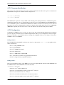
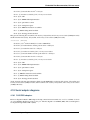
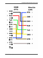
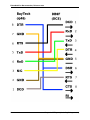
Serial adapter diagrams . . . . .
Startup . . . . . . . . . . . . . .
Switch driver . . . . . . . . . . .
TRX header . . . . . . . . . . .
UART driver . . . . . . . . . . .
WRT54GL . . . . . . . . . . . .
.
.
.
.
.
.
.
.
.
.
.
.
.
.
.
.
.
.
.
.
.
.
.
.
.
.
.
.
.
.
.
.
.
.
.
.
.
.
.
.
.
.
.
.
.
.
.
.
.
.
.
.
.
.
.
.
.
.
.
.
.
.
.
.
.
.
.
.
.
.
.
.
.
.
.
.
.
.
.
.
.
.
.
.
.
.
.
.
.
.
.
.
.
.
.
.
.
.
.
.
.
.
.
.
.
.
.
.
.
.
.
.
.
.
.
.
.
.
.
.
.
.
.
.
.
.
.
.
.
.
.
.
.
.
.
.
.
.
.
.
.
.
.
.
.
.
.
.
.
.
.
.
.
.
.
.
.
.
.
.
.
.
.
.
.
.
.
.
.
.
.
.
.
.
.
.
.
.
.
.
.
.
.
.
.
.
.
.
.
.
.
.
.
.
.
.
.
.
.
.
.
.
.
.
.
.
.
.
.
.
.
.
.
.
.
.
.
.
.
.
.
.
.
.
.
.
.
.
.
.
.
.
.
.
.
.
.
.
.
.
.
.
.
.
.
.
.
.
.
.
.
.
.
.
.
.
.
.
.
.
.
.
.
.
.
.
.
.
.
.
.
.
.
.
.
.
.
.
.
.
.
.
.
.
.
.
.
.
.
.
.
.
.
.
.
.
.
.
.
.
.
.
.
.
.
.
.
.
.
.
.
.
.
.
.
.
.
.
.
.
.
.
.
.
.
.
.
.
.
.
.
.
.
.
.
.
.
.
.
.
.
.
.
.
.
.
.
.
.
.
.
.
.
.
.
.
.
.
.
.
.
.
.
.
.
.
.
.
.
.
.
.
.
.
.
.
.
.
.
.
.
.
.
.
.
.
.
.
.
.
.
.
.
.
.
.
.
.
.
.
.
.
.
.
.
.
.
.
.
.
.
.
.
.
.
.
.
.
.
.
.
.
.
.
.
.
.
.
.
.
.
.
62
69
75
78
79
79
81
87
87
88
89
91
ARM ports (including Raspberry Pi)
5.1 Interrupt Handling (ARM) . . . .
5.2 Preemptive multitasking (ARM) .
5.3 arm-qemu . . . . . . . . . . . . .
5.4 Raspberry Pi port . . . . . . . . .
.
.
.
.
.
.
.
.
.
.
.
.
.
.
.
.
.
.
.
.
.
.
.
.
.
.
.
.
.
.
.
.
.
.
.
.
.
.
.
.
.
.
.
.
.
.
.
.
.
.
.
.
.
.
.
.
.
.
.
.
.
.
.
.
.
.
.
.
.
.
.
.
.
.
.
.
.
.
.
.
.
.
.
.
.
.
.
.
.
.
.
.
.
.
.
.
.
.
.
.
.
.
.
.
.
.
.
.
.
.
.
.
.
.
.
.
.
.
.
.
.
.
.
.
.
.
.
.
.
.
.
.
.
.
.
.
.
.
.
.
.
.
.
.
93
93
95
96
97
Teaching with Embedded Xinu
6.1 Monitors . . . . . . . . . . . . . . . . . . .
6.2 Compiler Construction With Embedded Xinu
6.3 Building a Backend Pool . . . . . . . . . . .
6.4 Deploying Xinu . . . . . . . . . . . . . . .
6.5 Building an Embedded Xinu laboratory . . .
6.6 Networking with Xinu . . . . . . . . . . . .
6.7 Student Built Xinu . . . . . . . . . . . . . .
6.8 Student Extended Xinu . . . . . . . . . . . .
6.9 Xinu Helper Class . . . . . . . . . . . . . .
6.10 Assignments . . . . . . . . . . . . . . . . .
6.11 Operating Systems Tracks . . . . . . . . . .
6.12 Networking . . . . . . . . . . . . . . . . . .
6.13 Compilers . . . . . . . . . . . . . . . . . .
6.14 Building a Backend Pool . . . . . . . . . . .
6.15 Workshops . . . . . . . . . . . . . . . . . .
6.16 Acknowledgements . . . . . . . . . . . . .
.
.
.
.
.
.
.
.
.
.
.
.
.
.
.
.
.
.
.
.
.
.
.
.
.
.
.
.
.
.
.
.
.
.
.
.
.
.
.
.
.
.
.
.
.
.
.
.
.
.
.
.
.
.
.
.
.
.
.
.
.
.
.
.
.
.
.
.
.
.
.
.
.
.
.
.
.
.
.
.
.
.
.
.
.
.
.
.
.
.
.
.
.
.
.
.
.
.
.
.
.
.
.
.
.
.
.
.
.
.
.
.
.
.
.
.
.
.
.
.
.
.
.
.
.
.
.
.
.
.
.
.
.
.
.
.
.
.
.
.
.
.
.
.
.
.
.
.
.
.
.
.
.
.
.
.
.
.
.
.
.
.
.
.
.
.
.
.
.
.
.
.
.
.
.
.
.
.
.
.
.
.
.
.
.
.
.
.
.
.
.
.
.
.
.
.
.
.
.
.
.
.
.
.
.
.
.
.
.
.
.
.
.
.
.
.
.
.
.
.
.
.
.
.
.
.
.
.
.
.
.
.
.
.
.
.
.
.
.
.
.
.
.
.
.
.
.
.
.
.
.
.
.
.
.
.
.
.
.
.
.
.
.
.
.
.
.
.
.
.
.
.
.
.
.
.
.
.
.
.
.
.
.
.
.
.
.
.
.
.
.
.
.
.
.
.
.
.
.
.
.
.
.
.
.
.
.
.
.
.
.
.
.
.
.
.
.
.
.
.
.
.
.
.
.
.
.
.
.
.
.
.
.
.
.
.
.
.
.
.
.
.
.
.
.
.
.
.
.
.
.
.
.
.
.
.
.
.
.
.
.
.
.
.
.
.
.
.
.
.
.
.
.
.
.
.
.
.
.
.
.
.
.
.
.
.
.
.
.
.
.
.
.
.
.
.
.
.
.
.
.
.
.
.
.
.
.
.
.
.
.
.
.
.
.
.
.
.
.
.
.
.
.
.
.
.
.
.
.
.
.
.
.
.
.
.
.
.
.
.
.
.
.
.
.
.
.
.
.
.
.
.
.
.
.
.
.
.
.
.
.
.
.
.
.
.
.
.
.
.
.
.
.
.
.
.
.
.
.
.
107
107
107
109
116
120
121
123
126
127
128
162
162
163
163
163
163
Projects
7.1 Curses . . . . . . .
7.2 WinX . . . . . . . .
7.3 WinXinu . . . . . .
7.4 WinXinu Installation
7.5 XinuPhone . . . . .
7.6 Xipx . . . . . . . .
.
.
.
.
.
.
.
.
.
.
.
.
.
.
.
.
.
.
.
.
.
.
.
.
.
.
.
.
.
.
.
.
.
.
.
.
.
.
.
.
.
.
.
.
.
.
.
.
.
.
.
.
.
.
.
.
.
.
.
.
.
.
.
.
.
.
.
.
.
.
.
.
.
.
.
.
.
.
.
.
.
.
.
.
.
.
.
.
.
.
.
.
.
.
.
.
.
.
.
.
.
.
.
.
.
.
.
.
.
.
.
.
.
.
.
.
.
.
.
.
.
.
.
.
.
.
.
.
.
.
.
.
.
.
.
.
.
.
.
.
.
.
.
.
.
.
.
.
.
.
.
.
.
.
.
.
.
.
.
.
.
.
.
.
.
.
.
.
.
.
.
.
.
.
.
.
.
.
.
.
.
.
.
.
.
.
.
.
.
.
.
.
.
.
.
.
.
.
.
.
.
.
.
.
.
.
.
.
.
.
.
.
.
.
.
.
.
.
.
.
.
.
.
.
.
.
.
.
.
.
.
.
.
.
.
.
.
.
.
.
165
165
166
169
170
172
175
Development
8.1 Git repository . . . . . . . .
8.2 Kernel Normal Form (KNF)
8.3 Trace . . . . . . . . . . . .
8.4 Build System . . . . . . . .
8.5 Porting Embedded Xinu . .
8.6 Documentation . . . . . . .
8.7 Systems Laboratory . . . .
.
.
.
.
.
.
.
.
.
.
.
.
.
.
.
.
.
.
.
.
.
.
.
.
.
.
.
.
.
.
.
.
.
.
.
.
.
.
.
.
.
.
.
.
.
.
.
.
.
.
.
.
.
.
.
.
.
.
.
.
.
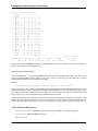
.
.
.
.
.
.
.
.
.
.
.
.
.
.
.
.
.
.
.
.
.
.
.
.
.
.
.
.
.
.
.
.
.
.
.
.
.
.
.
.
.
.
.
.
.
.
.
.
.
.
.
.
.
.
.
.
.
.
.
.
.
.
.
.
.
.
.
.
.
.
.
.
.
.
.
.
.
.
.
.
.
.
.
.
.
.
.
.
.
.
.
.
.
.
.
.
.
.
.
.
.
.
.
.
.
.
.
.
.
.
.
.
.
.
.
.
.
.
.
.
.
.
.
.
.
.
.
.
.
.
.
.
.
.
.
.
.
.
.
.
.
.
.
.
.
.
.
.
.
.
.
.
.
.
.
.
.
.
.
.
.
.
.
.
.
.
.
.
.
.
.
.
.
.
.
.
.
.
.
.
.
.
.
.
.
.
.
.
.
.
.
.
.
.
.
.
.
.
.
.
.
.
.
.
.
.
.
.
.
.
.
.
177
177
177
182
182
183
185
187
.
.
.
.
.
.
.
.
.
.
.
.
.
.
.
.
.
.
CHAPTER 1
Introduction
Note: This documentation, generated from files distributed with the Embedded Xinu source code, is currently under
development as a replacement for the Embedded Xinu Wiki (http://xinu.mscs.mu.edu).
Embedded Xinu is an ongoing research and implementation project in the area of Operating Systems and Embedded
Systems. Its original goal was to re-implement and port the Xinu Operating System to several embedded MIPS platforms, such as the Linksys WRT54GL router. Since then, Embedded Xinu has been ported to other platforms, such as
the QEMU MIPSel virtual environment and the Raspberry Pi; see the list of supported platforms. Although Embedded
Xinu is still being developed and ported to new platforms, a laboratory environment and curriculum materials are
already in use for courses in Operating Systems, Hardware Systems, Embedded Systems, Networking, and Compilers
at Marquette University and other colleges/universities.
The Embedded Xinu project was conceived and is supervised by Dr. Dennis Brylow and is being conducted by
both graduate and undergraduate students in the Systems Laboratory in the Math, Statistics, & Computer Science
department of Marquette University in Milwaukee, Wisconsin. The first major phase of work on Embedded Xinu
began in the Summer of 2006.
Our project partners include Dr. Bina Ramamurthy at University of Buffalo (with whom we shared an NSF CCLI
grant), Dr. Paul Ruth at University of Mississippi, and Dr. Doug Comer (father of Xinu) at Purdue University.
1.1 Getting started
To get started by downloading, compiling, and running Embedded Xinu, see Getting started with Embedded Xinu.
For information about the features of Embedded Xinu, see Components and Features (platform independent).
Information about specific platforms is also available:
• ARM ports (including Raspberry Pi)
• MIPS ports (including Linksys routers)
1.2 Teaching with Embedded Xinu
For curriculum guidance on adopting or adapting Embedded Xinu for undergraduate coursework, see Teaching with
Embedded Xinu.
For information about building an Embedded Xinu laboratory environment, see Building an Embedded Xinu laboratory.
1
Embedded Xinu Documentation, Release master
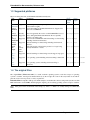
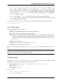
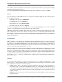
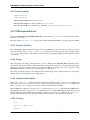
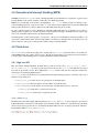
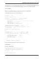
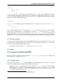
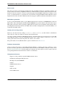
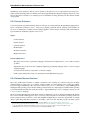
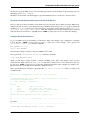
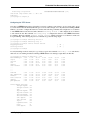
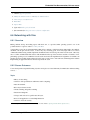
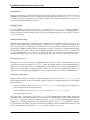
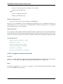
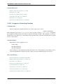
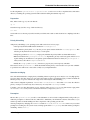
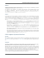
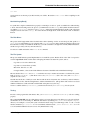
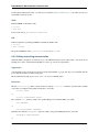
1.3 Supported platforms
These are all the platforms on which Embedded Xinu currently runs.
Platform
Status
Linksys
Supported
WRT54GL
Linksys
Supported
WRT54G
v8
Linksys
Probably
WRT54G Supported
v4
Linksys
Supported
WRT160NL
Linksys
Supported
E2100L
ASUS
Not
WLactively
330gE
maintained
mipselSupported
qemu
RaspSupported
berry
Pi
armSupported
qemu
Comments
This is our primary development platform, on which Xinu has
been tested thoroughly.
Tested and running at the Embedded Xinu Lab. Supported via
same code as WRT54GL.
PLATCrossFORM
target
value
wrt54gl mipsel
wrt54gl mipsel
The v4 is apparently the version on which WRT54GL is based,
and so although the Embedded Xinu Lab has not explicitly
tested it, it probably works.
Newer model of WRT54GL. Full O/S teaching core functioning,
including wired network interface.
Full O/S teaching core functioning, including wired network
interface.
This platform was working in the past but is no longer being
actively maintained or tested.
wrt54gl mipsel
Full O/S teaching core functioning, network support in progress.
mipsel-qemu
mipsel
Core operating system including wired networking is functional.
arm-rpi arm-none-eabi
Core operating system, excluding wired networking, is
functional.
arm-qemuarm-none-eabi
wrt160nlmips
e2100l
mips
wl330ge mipsel
1.4 The original Xinu
The original Xinu (“Xinu is not unix”) is a small, academic operating system to teach the concepts of operating
systems to students. Developed at Purdue University by Dr. Douglas E. Comer in the early 1980s for the LSI-11
platform, it has now been ported to a variety of platforms.
Embedded Xinu is an update of this project which attempts to modernize the code base and port the system to modern
RISC architectures such as MIPS, while keeping the original goals of teaching operating system concepts to students.
Note: Most places in this documentation that simply say “Xinu” or “XINU” are actually talking about Embedded
Xinu.
2
Chapter 1. Introduction
CHAPTER 2
Getting started with Embedded Xinu
This section describes how to download and compile Embedded Xinu, assuming you are using a UNIX operating
system such as Linux or Mac OS X, or at least a UNIX-compatible environment such as Cygwin.
• Downloading the source code
• Choosing a platform
• Setting up a cross-compiler
– Option 1: Install cross-compiler from repository
– Option 2: Build cross-compiler from source
* Native development environment
* binutils
* gcc
* Testing the cross compiler
• Compiling Embedded Xinu
– Makefile variables
– Makefile targets
• Next steps
• Other resources
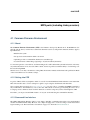
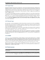
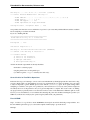
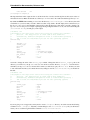
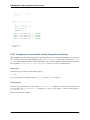
2.1 Downloading the source code
Stable versions of Embedded Xinu may be downloaded from http://xinu-os.org/Downloads.
The development version (recommended, as of this writing) is stored in a repository using the git source code management system. To download it, install git and run the following command:
$ git clone https://github.com/xinu-os/xinu
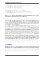
You then should have a copy of the source:
$ cd xinu
$ ls -F
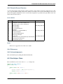
apps/
compile/
AUTHORS device/
docs/
include/
lib/
LICENSE
loader/
mailbox/
mem/ README.md system/
network/ shell/ test/
Note that Embedded Xinu is licensed under a BSD-style license; see the copyright information in the source distribution for more details.
3
Embedded Xinu Documentation, Release master
2.2 Choosing a platform
See the list of platforms supported by Embedded Xinu.
Note: Each supported platform corresponds to a subdirectory of compile/platforms/.
If you do not have “real embedded hardware” available and simply would like to try out Embedded Xinu from your
laptop or desktop, you can use either the mipsel-qemu or the arm-qemu ports, each of which runs in the QEMU system
emulator.
2.3 Setting up a cross-compiler
Since most of Embedded Xinu’s supported platforms do not share the same processor architecture as an x86 workstation, building Embedded Xinu typically requires an appropriate cross compiler for the C programming language. The
processor architecture of each Embedded Xinu platform is listed under Cross-target in the list of supported platforms;
note that this is the value to pass to --target when configuring binutils and gcc.
Currently, only the gcc compiler is supported. (clang does not yet work!)
2.3.1 Option 1: Install cross-compiler from repository
Some Linux distributions already have popular cross compilers available in their software repositories. When available, this can be used as a quick alternative to building from source.
2.3.2 Option 2: Build cross-compiler from source
This section documents how to build and install binutils and gcc from source in a cross-compiler configuration.
Native development environment
Before you can build anything from source, you first need appropriate development tools for your native platform,
such as gcc and make.
• On Linux systems, these tools can be found in the software repositories under various names and groupings,
depending on the Linux distribution.
• On Windows via Cygwin, these tools can be found under the “devel” category when you run the setup program.
• On Mac OS X, these tools come with Xcode.
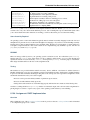
binutils
Before building the C compiler itself, the corresponding binary utilities including the assembler and linker must be
installed.
Note: Good practice when building any software package is to use a normal user account, and only acquire root
privileges with sudo for installation (step 6 below).
1. Download a recent release of GNU binutils, for example:
4
Chapter 2. Getting started with Embedded Xinu
Embedded Xinu Documentation, Release master
$ wget ftp://ftp.gnu.org/gnu/binutils/binutils-2.23.tar.gz
2. Untar the binutils source:
$ tar xvf binutils-2.23.tar.gz
3. Create and enter a build directory:
$ mkdir binutils-2.23-build
$ cd binutils-2.23-build
4. Configure binutils for the appropriate target, for example:
$ ../binutils-2.23/configure --prefix=/opt/mipsel-dev --target=mipsel \
--disable-nls
The argument given to --prefix is the location into which to install the binutils, and is of your choosing.
Typical locations would be a subdirectory of /opt or /usr/local. (Note that installing into these locations
requires sudo privilege in step 6. Normally, it is also possible to install software into a user’s home directory,
which does not require the sudo privilege.)
The argument given to --target is the target which the binutils will target, and must be set appropriately for
the desired Embedded Xinu platform, as shown under Cross-target in the list of supported platforms.
--disable-nls simply saves time and space by not supporting any human languages other than English.
You can skip this option if you want.
5. Build binutils:
$ make
6. Install binutils:
$ sudo make install
gcc
1. Download a recent release of the GNU Compiler Collection, for example:
$ wget ftp://ftp.gnu.org/gnu/gcc/gcc-4.8.2/gcc-4.8.2.tar.bz2
2. Untar the gcc source:
$ tar xvf gcc-4.8.2.tar.bz2
3. Create and enter a build directory:
$ mkdir gcc-4.8.2-build
$ cd gcc-4.8.2-build
4. Configure gcc for the appropriate target, for example:
$ ../gcc-4.8.2/configure --prefix=/opt/mipsel-dev --target=mipsel \
--enable-languages=c,c++ --without-headers --disable-nls
--prefix and --target must be exactly the same as those chosen for the binutils installation.
--enable-languages=c,c++ ensures that only C and C++ compilers are built, not the compilers for
other languages such as Ada and Fortran that are also supported by the GNU Compiler Collection. Note:
2.3. Setting up a cross-compiler
5
Embedded Xinu Documentation, Release master
Embedded Xinu does not actually contain C++ code, so if desired this could be stripped down to simply
--enable-languages=c.
--without-headers is needed when there is no libc (standard C library) installed for the target platform,
as is the case here.
--disable-nls simply saves time and space by not supporting any human languages other than English.
You can skip this option if you want.
5. Build gcc:
$ make all-gcc all-target-libgcc
Tip: gcc can take a while to build (upwards of half an hour). You can add the argument -jN to make, where
N is an integer, to run multiple compilation jobs in parallel.
6. Install gcc:
$ sudo make install-gcc install-target-libgcc
Testing the cross compiler
First, for convenience you may wish to make the cross-utilities available under their unqualified names by updating
$PATH, for example:
export PATH="$PATH:/opt/mipsel-dev/bin"
The above should go in a shell startup file such as $HOME/.bashrc.
Test the compiler by creating a file test.c:
void f(void)
{
}
and compiling it with, for example:
mipsel-gcc -c test.c
This should succeed and produce a file test.o without any error messages.
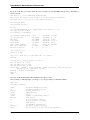
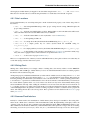
2.4 Compiling Embedded Xinu
Having built a cross-compiler if needed, compiling Embedded Xinu now requires running make to process the
Makefile in the compile/ directory and specifying an appropriate PLATFORM, for example:
$ make -C compile PLATFORM=wrt54gl
Additional details follow.
2.4.1 Makefile variables
Several variables can be defined on the make command line to customize the build.
• PLATFORM specifies the name of a directory in compile/platforms/ that is the Embedded Xinu platform
for which to build the kernel.
6
Chapter 2. Getting started with Embedded Xinu
Embedded Xinu Documentation, Release master
• COMPILER_ROOT specifies the location of the executables for the compiler and binutils necessary to compile, assemble, and link code for the target platform. COMPILER_ROOT must include
any target prefix that the executables may be prefixed with.
Example for ARM-based platforms:
/opt/arm-dev/bin/arm-none-eabi-. Or, if the executables are on your $PATH, you could simply
specify, for example, arm-none-eabi-; however, that (or the corresponding prefix for a non-ARM-based
PLATFORM) is already the default.
• DETAIL can be defined as -DDETAIL to enable certain debugging messages in Embedded Xinu.
• VERBOSE can be defined to any value to cause the build system to print the actual command lines executed
when compiling, linking, assembling, etc.
To override any of the above variables, you must pass it as an argument to make, like in the following example:
$ make PLATFORM=arm-rpi
2.4.2 Makefile targets
The following Makefile targets are available:
• xinu.boot Compile Embedded Xinu normally. This is the default target.
• debug Same as xinu.boot, but include debugging information.
• docs Generate the Doxygen documentation for Embedded Xinu. This requires that Doxygen is installed. Note:
to eliminate irrelevant details in the documentation, the documentation is parameterized by platform; therefore, the exact documentation that’s generated will depend on the current setting of PLATFORM (see Makefile variables).
• clean Remove all object files.
• docsclean Remove documentation generated by make docs.
• realclean Remove all generated files of any kind.
The above covers the important targets, but see the compile/Makefile for a few additional targets that are available.
Note: Older versions of Embedded Xinu had a make depend target to generate header dependency information.
This has been removed because this information is now generated automatically. That is, if you modify a header, the
appropriate source files will now be recompiled automatically.
2.5 Next steps
Typically, after compiling Embedded Xinu, a file xinu.boot containing the kernel binary is produced. Actually
running this file is largely platform-dependent. Just a few examples are:
• Raspberry Pi: See Booting the Raspberry Pi and Downloading, compiling, and running XinuPi.
• Mipsel-QEMU: See mipsel-qemu.
• ARM-QEMU See arm-qemu.
Places to go next:
• Components and Features (platform independent)
• Teaching with Embedded Xinu
2.5. Next steps
7
Embedded Xinu Documentation, Release master
2.6 Other resources
• GCC Cross-Compiler (OSDev Wiki)
8
Chapter 2. Getting started with Embedded Xinu
CHAPTER 3
Components and Features (platform independent)
This is the documentation for major Embedded Xinu components and features relevant to multiple platforms. Platformspecific documentation can be found in MIPS ports (including Linksys routers) and ARM ports (including Raspberry
Pi).
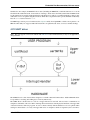
3.1 Preemptive multitasking
Like virtually all modern operating systems, XINU supports preemptive multitasking, which makes it appear that
multiple threads are executing at the same time on the same processor. Support for preemptive multitasking consists
of support for multiple threads combined with a preemption mechanism.
3.1.1 Multiple threads
XINU supports multiple threads, but only one can execute at a time. A thread context refers to the saved state of a
thread, primarily CPU registers. XINU platforms must implement two functions to allow creating new threads and
switching between threads using their thread contexts:
• setupStack(), which is responsible for setting up the stack of a new thread to include an initial thread context and procedure arguments. This routine is typically implemented in C. It is called internally by create(),
located in system/create.c. For an example, see system/arch/arm/setupStack.c.
• ctxsw(), which is responsible for switching between threads. More specifically, this routine must save the
thread context of the current thread and restore the thread context of the new thread. This routine is always
implemented in assembly language. For an example, see system/arch/arm/ctxsw.S.
Since different CPU architectures use different registers and calling conventions, the size and format of a thread context
varies depending on the CPU architecture. Note that since thread contexts are created in both setupStack() and
ctxsw(), these two routines must create contexts that are compatible, at least to the extent that ctxsw() can either
start a new thread or resume an existing thread.
Other articles describe this in more detail for specific architectures:
• Preemptive multitasking (ARM)
3.1.2 Preemption
Preemption occurs when the timer interrupt occurs and XINU attempts to reschedule the currently executing thread,
which results in a call to ctxsw(), described above, that may switch to a different thread context. (We say may
because the code is written such that ctxsw() is called when the same thread is rescheduled to itself, in which
9
Embedded Xinu Documentation, Release master
case ctxsw() restores the saved context immediately and is a no-op.) The means of generating a timer interrupt is
platform-dependent and may even differ among platforms that share the same CPU architecture. For an example, see
BCM2835 System Timer, which is used in the Raspberry Pi, an ARM-based platform.
3.2 Shell
The XINU shell, or xsh, is a subsystem that acts as a simple command-line interface for human interaction with the
operating system. It is implemented in shell/.
3.2.1 How it works
Starting a shell
Note: This section explains how to programatically start a shell. By default, this is already done by system/main.c.
An instance of the XINU shell can be started by creating a thread to execute the shell() procedure. This procedure is
declared as follows:
thread shell(int indescrp, int outdescrp, int errdescrp);
The shell will read and execute commands from the character device specified by indescrp. It shell will send any
output written to stdout by the executed shell commands to the device specified by outdescrp, and any output
written to stderr to to the device specified by errdescrp.
A typical instance of spawning a shell, as seen in system/main.c, is:
ready(create
((void *)shell, INITSTK, INITPRIO, "SHELL0", 3,
CONSOLE, CONSOLE, CONSOLE), RESCHED_NO);
The above uses the CONSOLE device for all input and output, which typically is set up as TTY device that wraps around
the first serial port, or UART:
open(CONSOLE, SERIAL0);
If additional input or output devices, such as keyboards, framebuffers, or additional serial ports are available, additional
shell threads may be started on them.
Reading and executing commands
When a user enters a command at the shell, the lexan() function divides the string of input into tokens. Command
name, arguments, quoted strings, backgrounding, and redirection tokens are all recognized and divided by lexan().
After the command is parsed, the shell uses the tokens to properly execute the given command. The shell first checks
for the backgrounding ampersand (‘&’), which should only appear as the last token. The shell is designed to handle
redirection, but does not currently do so since XINU’s file system is in development.
Next, the command is looked up in the command table defined at the top of shell/shell.c. Each entry in the command
table follows the format of command name, is the command built-in (ie can the command run in the background), and
the function that executes the command: {"command_name", TRUE / FALSE, xsh_function},.
Built-in commands are executed by calling the function that implements the command. All other commands are
executed by creating a new process. If the user did not include the backgrounding flag in the input, the shell waits until
the command process has completed before asking for more input.
10
Chapter 3. Components and Features (platform independent)
Embedded Xinu Documentation, Release master
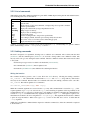
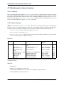
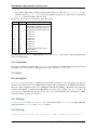
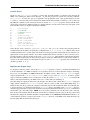
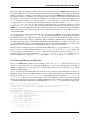
3.2.2 List of commands
Although the actual shell commands available in a given build of XINU depend on the platform and enabled features,
some of the important ones are listed below:
Command
clear
exit
help
kill
memstat
memdump
ps
reset
sleep
test
testsuite
uartstat
Description
clears the shell’s output
quits the shell
displays the list of supported commands, or displays help about a specific command
kills the specified thread
displays the current memory usage and prints the free list
dumps a region of memory
displays a table of running processes
soft resets the system
puts the executing thread to sleep for the specified time
does nothing by default, but developers can temporarily add code here
run a series of tests to see if the system is functioning properly
display information about a UART
A full list of commands can be obtained from the shell by running the help command. Help on a specific command
can be obtained using COMMAND --help or help COMMAND.
3.2.3 Adding commands
The shell is designed to be expandable, allowing users to add their own commands. The code that runs the shell
(shell/shell.c) and the command parser (shell/lexan.c) do not need to change when a new command is added. The
majority of the work goes into writing the actual command. After the command is written, three items must be added
to the system:
• the function prototype needs to be added to the header file (include/shell.h),
• the command table (shell/shell.c) must be updated, and
• the make file (shell/Makerules) must build the file containing the function.
Writing the function
The command should be given its own C source file in the shell/ directory, following the naming convention
xsh_command.c. All command files should include kernel.h and shell.h, along with any other headers
necessary for the command. Function names for commands follow the same naming convention as the source file:
xsh_command. The method signature for a command is:
shellcmd xsh_command(int nargs, char *args[])
Within the command, arguments are accessed via the args array. The command name is located in arg[0]. Subsequent arguments, up to nargs are accessed via arg[n]. Error checking of arguments is the responsibility of the
command function. It is good practice to check for the correct number of arguments; remember the command name is
counted in nargs, so a command without any arguments should have nargs == 1. Although not required, command functions should also allow for an argument of --help as arg[1]. This argument should cause the command
to print out usage information. When a user types help COMMAND in the shell, the COMMAND is called with the
--help argument.
Additional code within the command function depends on what the command does. After the command is completed
it should return OK.
3.2. Shell
11
Embedded Xinu Documentation, Release master
Add to command table
After the command function is written, the command needs to be added to the command table so the shell is aware of
the command. The command table is an array of centry (command entry) structures defined in shell/shell.c.
Each entry in the command table follows the format of command name, is the command built-in (ie can the command
run in the background), and the function that executes the command: {"command_name", TRUE / FALSE,
xsh_function},.
Add to header and makefile
To complete the process, add the function prototype to the shell header file include/shell.h:
shellcmd xsh_command(int, char *[]);
Lastly, add the command function source file to the makefile (shell/Makerules) under the C_FILES group to
ensure the command is compiled into the XINU boot image.
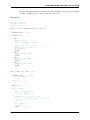
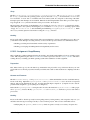
Example
We will run through a brief implementation of adding an echo command to the system.
Write the function
Begin by creating the source file in shell/xsh_echo.c. Since all commands take the same arguments (as passed
by the shell), we get:
#include <kernel.h>
#include <stdio.h>
#include <string.h>
/**
* Shell command echos input text to standard out.
* @param stdin descriptor of input device
* @param stdout descriptor of output device
* @param stderr descriptor of error device
* @param args array of arguments
* @return OK for success, SYSERR for syntax error
*/
shellcmd xsh_echo(int nargs, char *args[])
{
int i; /* counter for looping through arguments */
/* Output help, if ’--help’ argument was supplied */
if (nargs == 2 && strcmp(args[1], "--help") == 0)
{
fprintf(stdout, "Usage: clear\n");
fprintf(stdout, "Clears the terminal.\n");
fprintf(stdout, "\t--help\t display this help and exit\n");
return SYSERR;
}
/* loop through the arguments printing each as it is displayed */
for ( i = 1; i < nargs; i++ )
{
fprintf(stdout, "%s ", args[i]);
12
Chapter 3. Components and Features (platform independent)
Embedded Xinu Documentation, Release master
}
/* Just so the next prompt doesn’t run on to this line */
fprintf(stdout, "\n");
/* there were no errors so, return OK */
return OK;
}
Add the function to the command table
While we are in the shell/ directory, we’ll modify the command table found at the top of shell/shell.c. Since we are
adding the echo command, we’ll most likely want the user input at the shell to be “echo,” this is not a builtin function
(FALSE), and the function that supports this is xsh_echo. Giving us the entry:
{ "echo", FALSE, xsh_echo }
Add the function prototype to the include file
Next we must add the prototype of the function to the shell include file in include/shell.h. This is simply done by
adding the line:
shellcmd xsh_echo(int, char *[]);
Add the file to the Makefile
Finally (and most importantly) we add the function to the Makefile to make sure that it is built by the compiler. We do
this by finding the line beginning with “C_FILES =” in shell/Makerules and adding xsh_echo.c to the end of
it.
Compile and run, and you should now have a working implementation of the echo command on your XINU system!
3.2. Shell
13
Embedded Xinu Documentation, Release master
3.3 TTY driver
XINU’s TTY driver, located in device/tty/, serves as an intermediary device between hardware device drivers and user
applications to provide line buffering of input and cooking of input and output. The driver is purely software oriented
and makes no direct communication with physical hardware. Instead, the TTY driver relies on an underlying device
driver to communicate directly with the hardware. The XINU Shell utilizes a TTY device to line buffer and cook user
input read from another device, such as a UART.
3.3.1 Open & Close
ttyOpen(), which should be called via open(), associates a TTY with an underlying char-oriented hardware device.
The underlying device driver must provide both getc() and putc() functions for the TTY to obtain input and send
output character by character. The device should already be opened and initialized before the TTY is opened. When
a TTY is opened, its device control block, input buffer, and flags are initialized. No input flags are set when a TTY
device is opened. The TTY_ONLCR output flag is set when a TTY device is opened.
ttyClose(), which should be called via close(), disassociates a TTY from its underlying device and resets the TTY’s
device control block.
3.3.2 Read
The TTY driver reads characters from an underlying device driver using the devices getc() function. Input is first
buffered in the TTY driver’s circular buffer before being copied to the user buffer supplied as a parameter in the
ttyRead() function call.
The ttyRead() function begins by checking the ieof flag to determine if the EOF character (Control+D) was read during the last call to ttyRead() If the ieof flag is set, the function returns the EOF constant, defined in stddef.h.
EOF is only returned once for each EOF character read by the TTY driver. A call made to ttyRead() after EOF was
returned, will result in an attempt to read more characters from the underlying device driver.
If the TTY_IRAW flag is set, the TTY driver performs no line buffering or line editing (input cooking). The user buffer
is first filled from any data remaining in the TTY driver’s input buffer from the last ttyRead() call. The remaining
portion of the user supplied buffer is filled by reading characters from the underlying device driver.
14
Chapter 3. Components and Features (platform independent)
Embedded Xinu Documentation, Release master
The TTY driver performs line buffering and line editing (input cooking) when the TTY_IRAW flag is not set. Characters are read from the underlying device driver until a line delimiter is read or the TTY driver’s input buffer is full.
Lines may be terminated with the newline (LF or ’\n’) or end of file (EOF or ASCII character 0x04) characters. If
the TTY_ECHO flag is set, each character is output as it is read.
Special handling is required for some characters to perform line editing (input cooking). If the TTY driver’s input
buffer contains characters, backspace (BS or ’\b’) and delete (DEL or ASCII character 0x7F) remove the last character from the TTY’s input buffer. The newline and carriage return (CR or ’\r’) characters are cooked if certain input
flags are set. The end of file character causes the ieof flag to be set. Any other unprintable characters are ignored.
After a line of input is buffered in the TTY’s device driver, the user supplied buffer is filled from the TTY’s input
buffer. If the end of file character was the only character read, the EOF constant is returned. Otherwise, the number of
characters read into the user buffer is returned.
The TTY driver has the following input flags:
• TTY_IRAW - reads input unbuffered and uncooked
• TTY_INLCR - converts ’\n’ to ’\r’
• TTY_IGNCR - ignores ’\r’
• TTY_ICRNL - converts ’\r’ to ’\n’
• TTY_ECHO - echoes input
3.3.3 Write
The TTY driver does not buffer output; in ttyWrite(), it writes characters directly to an underlying device driver. The
TTY driver cooks newlines (LF or ’\n’) and carriage returns (CR or ’\r’) if certain output flags are set.
The TTY driver has the following output flags:
• TTY_ONLCR - converts ’\n’ to ’\r\n’
• TTY_OCRNL - converts ’\r’ to ’\n’
3.3.4 Control
The TTY driver has four control functions: two to set and clear input flags and two to set and clear output flags. Each
of control functions returns the previous state of the flags being changed. These are implemented in ttyControl() and
should be called via control().
3.4 Memory management
Memory management is an important aspect of any operating system. As such, XINU makes use of some aspects of
the underlying hardware to build up a simple-to-understand memory management system.
3.4.1 Memory allocators
XINU maintains two memory allocators that work in tandem to provide dynamic memory to both kernel and user
software. The first allocator is the kernel allocator which allocates small chunks of memory from the global memory
heap as needed by the kernel. The second allocator is a user allocator, that allocates memory from a per-thread memory
heap as needed by user processes.
3.4. Memory management
15
Embedded Xinu Documentation, Release master
Kernel allocator
The most basic memory allocator in the system is the kernel allocator which uses the memget and memfree functions. This operates on the global kernel heap that uses the memlist global variable. In this allocator the kernel
developer is trusted to keep track of the accounting information for memory blocks. This makes a rather straightforward API.
void *memptr = memget(nbytes);
memfree(memptr, nbytes);
As can be seen in the above API, the allocation function takes a single parameter (nbytes) which is the number
of bytes requested. The deallocation function takes two parameters (memptr and nbytes), where memptr is the
memory address allocated via the memget function and nbytes is the number of bytes requested with the original
call.
User allocator
Unlike the kernel allocator, the user allocator does not trust the programmer to remember the amount of memory
requested and instead stores the accounting information immediately before the allocated memory. To the programmer
the API for user memory is simply:
void *memptr = malloc(nbytes);
free(memptr);
This allocator works on a per-thread memory list of free memory, this allows memory to be owned by the calling
thread and prevents other threads from having access to the memory. This forms the basis of memory protection.
When a request for memory comes in to the allocator, it attempts to satisfy the request with free memory that has
already been allocated to thread. If that fails, the allocator will then attempt to acquire memory from the region
allocator (described below). Since the region allocator works at page granularity, any excess memory is inserted into
the thread’s free memory list for future requests. When a block of memory is free’d, the memory is returned to the
thread’s free memory list.
It is not until the thread is killed that the memory is removed from the thread’s protection domain and made available
to the region allocator.
Region allocator
The region allocator works beneath the user allocator and is initialized during the boot process. During system boot
XINU uses UHEAP_SIZE as defined in xinu.conf to allocate memory for the user heap. This memory is allocated
via the kernel memget() function and is then passed to the memRegionInit() function. Once the region allocator
is initialized, the only user level interface to the region allocator is hidden behind the malloc and free routines.
3.4.2 Memory protection
Note: This section applies to MIPS platforms only.
Since XINU has limited resources to work with it does not provide a virtual memory system. It does take advantage
of separate address spaces for each user thread running in the system, which provides simple memory protection for
low overhead costs. As such, when allocating pages to the thread via the user allocator those pages will be mapped to
the protection domain of the currently running thread. These protection domains are inserted into a single global page
table, that hold all the page table entries and the address space identifier of the protected page.
16
Chapter 3. Components and Features (platform independent)
Embedded Xinu Documentation, Release master
In the memory protection subsystem, the default behaviour is to map all the kernel pages (i.e. pages that are not in the
user heap), to every thread in the system as read only. This allows all threads to read from kernel data, but prevents
overwriting of that data.
Translation lookaside buffer
Note: This section applies to MIPS platforms only.
To facilitate memory protection, XINU uses the translation lookaside buffer (TLB) built into the MIPS processors of
the WRT54GL series of routers. When a piece of software attempts to access memory in the user segment, a TLB
load or store exception will occur. When this occurs the processor jumps to a specific exception handler which allows
the kernel to look up the page table entry, check if the faulting thread is in the same memory space as the entry, and
load the entry into the TLB. If there is no mapping or the thread is not in the same address space, a memory protection
violation occurs and the thread is killed.
3.5 Message passing
Message passing is one method used by XINU threads for interprocess communication. It allows threads to send
individual messages to other threads by using the system calls send, receive, and recvclr. Each thread has
memory allocated for a single message in its thread control block specifically for messages sent and received using
this method. This form of message passing should not be confused with the mailbox messaging queue system also
used for interprocess communication.
Upon creation, each thread is allocated memory in its thread control block for two fields which apply to this message
passing system: a 4 byte (int type) message box to contain a single message sent to this thread, and a one byte flag
(bool type) to signal if there is an unreceived message waiting in that thread’s message box.
Threads use the functions send(tid_typ tid, int msg), receive(), and recvclr() to utilize this system of message passing.
send(tid_typ tid, int msg) delivers the message passed in as the parameter msg to the message box in the
thread control block of the thread with a thread id of tid, also passed in as a parameter. send will always yield the
processor by calling reschedule if the receiving thread was in a state of waiting to receive a message (THRRECV).
receive() returns the message waiting in the message box of the thread control block of the thread which called
receive. If there is no message waiting for the thread then the thread will go into a state of waiting to receive a
message (THRRECV) until a message is passed to the thread.
recvclr() is a non-blocking version of receive(). If there is a message waiting in the message box of the
thread control block of the thread which called receive it returns the message. If there is no message waiting for
the thread, then it will simply return OK, signifying that there was no message waiting for the thread. Notice that this
does not block the thread that called receive and will always immediately return either the message or OK.
3.6 Mailboxes
In XINU, a mailbox is a messaging queue used for interprocess communication. Mailboxes should not to be confused
with the single message passing capability built into the thread control block which uses send() and receive().
XINU allows for a finite number of mailboxes to be created. Each mailbox is identified by a number. Any number of
processes can send and receive messages from the mailbox, provided the processes know the correct mailbox number.
When a new mailbox is created (allocated) a maximum number of messages allowed in the queue must be specified.
Memory for the messages is allocated when the mailbox is created. Once the mailbox message queue is full, processes
3.5. Message passing
17
Embedded Xinu Documentation, Release master
that attempt to send a message must wait for space in the queue. If the queue is empty, processes that attempt to receive
a message must wait for a message to be enqueued. A message is 4 bytes long (int type).
When a mailbox is deleted all remaining messages in the queue are destroyed. Processes waiting to send or receive
are released from the wait state.
3.7 Standard C Library
•
•
•
•
•
Overview
API
Deviations from standard behavior
Platform-specific overrides
References
3.7.1 Overview
The XINU C library, or libxc, is a “minimal” standard C library distributed with XINU. It is intended to be easy to
understand rather than high-performance or fully standards compliant. However, the functions that are implemented
are mostly the same as the standard versions except as documented below.
3.7.2 API
For the sake of reducing redundancy, the full API (functions and macros) provided by libxc is not documented on this
page. Instead, every function implemented in the lib/libxc directory has a detailed comment describing its behavior.
Note that every C source file in this directory implements a separate externally visible function.
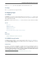
The library headers are:
Header
ctype.h
limits.h
stdarg.h
stdint.h
stdio.h
stdlib.h
string.h
Description
Character types
Limits of integer types
Variable argument lists
Fixed-width integer types
Standard input and output
Standard library definitions
String operators
stddef.h is also present and defines some XINU-specific types in addition to the standard offsetof, size_t, and
NULL.
3.7.3 Deviations from standard behavior
For various reasons (usually simplicity), libxc deviates from other C libraries in the following ways:
• Many standard functions (and some headers) are simply not implemented. Examples: Floating-point mathematics functions; setjmp() and longjmp(); wide character support; locale support; time functions; complex
arithmetic.
• Formatted printing and scanning support only a limited range of format specifiers. See _doscan() and _doprnt()
for more information.
18
Chapter 3. Components and Features (platform independent)
Embedded Xinu Documentation, Release master
• The ctype functions declared in include/ctype.h do not handle EOF (end-of-file) as specified by C99.
• putc() is not implemented in libxc. In Xinu it’s actually a “system call”, and its arguments are reversed
compared to the standard putc(). Use fputc() or putchar() to get standard behavior.
• The stdio functions do not buffer the output like a standard implementation would; instead they write directly to
a device descriptor (rather than a FILE stream).
• strlcpy() is implemented, even though this is technically a nonstandard BSD extension. We do this because
several places in XINU were incorrectly calling strncpy() when they expected behavior equivalent to strlcpy().
3.7.4 Platform-specific overrides
Sometimes, one would like to build the C library with optimized implementations of certain functions, usually string
functions like memcpy() or strlen() written in assembly language for a particular architecture. In line with the goals
of XINU, this is discouraged because this makes it more difficult for people to understand the code and find where a
given function is actually defined for a given platform.
If you nevertheless still wish to do this, please do not modify the code in libxc itself unless absolutely necessary. Instead, define a variable LIBXC_OVERRIDE_CFILES in the platform-specific platformVars file (e.g.
compile/platforms/$(PLATFORM)/platformVars) that is a list of C source files in libxc that should not
be compiled. For example, if you override memcpy(), then you would specify:
LIBXC_OVERRIDE_CFILES := memcpy.c
in platformVars. You then need to provide your own implementation of the corresponding function(s), but please do it
in a platform-specific directory (e.g. system/platforms/$(PLATFORM)) instead of in here.
This method still has the limitation that the replacement function(s) will not be included in libxc.a itself, only in
the kernel as a whole. However, this is inconsequential for XINU where everything gets linked into a single kernel
image.
3.7.5 References
• C standard library - Wikipedia
• C99 standard
• Brian Kernighan and Dennis Ritchie. The C Programming Language, second edition. Prentice Hall.
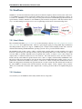
3.8 Networking
This is the documentation for Embedded Xinu‘s networking subsystem, including the files under network/ as well as
certain protocols implemented as device drivers (e.g. device/tcp/ and device/udp/).
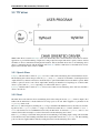
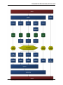
3.8.1 Networking stack design
The new network stack design does not have a NET device. The read and write device function paradigm does not
map well to the network stack. TCP, UDP, and RAW sockets do not read from a network device, rather a network
receive thread calls a chain of receive functions to process the packet at each layer in the network stack. A write
function does not work well for sending a packet since the final destination of the packet is not known until the IP
and/or ARP layers. The write device function assumes the thread calling write knows exactly which device to which
the data should be written. A table of netif structures (separate from devtab, the table of devices) is still maintained to
3.8. Networking
19
Embedded Xinu Documentation, Release master
store configuration and accounting information for each underlying device (ETH, etc.) with which the network stack
is receiving and sending packets.
A network interface is setup using the netUp() function. An underlying device, IP address, mask, and gateway must
be provided when calling netUp().
Note: netUp() does not have DHCP built into it. Instead, for DHCP configuration dhcpClient() should be called
before calling netUp(). The DHCP client will interact directly with the underlying device (ETH, etc.) without using
the network stack in order to acquire IPv4 information.
Network receive threads continually read incoming packets from an underlying device. Each network interface has one
or more network receive threads running. The netRecv() function includes an infinite loop which reads a packet
from the underlying device and calls ipv4Recv() or arpRecv() depending on the type of the packet. The packet
is read into a buffer declared as a local variable within the netRecv function. At the IP layer ipv4Recv() calls
tcpRecv(), udpRecv(), rawRecv(), or passes the packet to a routing thread. No sending of packets should
ever occur under a network receive thread. For protocols in which an incoming packet may generate the need to send
a reply packet, the protocol must have a separate thread for sending. For example, if an incoming TCP packet contains
data which needs to be acknowledge, and tcpRecv() should set a flag or send a message to a TCP monitor thread
which will proceed to send the acknowledgement.
A global buffer pool is allocated for storing outgoing packets. One pool exists for use by all network interfaces.
When sending a packet, the sending function (ex. tcpSend()) obtains a buffer from the pool, calls the appropriate
lower-level send function (ex. ipv4Send()), and, after the function returns, returns the buffer to the pool.
The network stack is designed to treat the Xinu backend as both a router and a multi-homed host. Packets received on
any of a backend’s network interfaces may be destined for the backend or may need to be routed to another network
destination. The network layer (IP layer) determines how to handle incoming packets. In the function ipv4Recv(),
the destination of an IP packet is compared against the IP address and broadcast address for every active network
interface. If the destination address of the IP packet matches the IP address of the interface on which it was received
or the IP address of any other network interface, the packet is passed to the appropriate transport layer receive function
(udpRecv(), tcpRecv(), etc.). IP packets whose destination does not match with one of the active network
interfaces are passed to the routing module of the network stack, i.e. the function rtRecv() is called. In rtRecv()
the packet is copied into a buffer from the global buffer pool and placed on a queue for a routing thread to process.
Currently, the network stack does not use a selective drop algorithm when the router is overloaded; once the queue
of packets to route is full, all subsequent packets which require routing are dropped. A routing thread processes
each packet on the routing queue. If no route is known, the packet is dropped; otherwise the TTL is decrement,
the checksum is recalculated and the netSend() function is called. Packets being sent from the transport layer
(udpSend(), tcpSend(), etc) are not passed to the routing thread. The transport layer calls ipv4Send() which
performs a route table lookup, sets up the IP packet header and calls netSend().
20
Chapter 3. Components and Features (platform independent)
Embedded Xinu Documentation, Release master
3.8. Networking
21
Embedded Xinu Documentation, Release master
3.8.2 ARP
As part of its networking subsystem, XINU supports the Address Resolution Protocol (ARP), which allows protocol
addresses (e.g. IPv4 addresses) to be translated into hardware addresses (e.g. MAC addresses).
ARP daemon
The ARP daemon is run automatically on start up and waits for incoming ARP packets. Incoming packets are filtered
through netRecv() and ARP requests/replies are sent on to the ARP Daemon.
Use of ARP when sending packets
Callers of netSend() do not need to specify hwaddr, the hardware address of the destination computer, and can
leave this parameter as NULL. In such cases arpLookup() is called to try to map the destination protocol address to a
hardware address. This first searches the ARP table, but if the relevant entry is not found, an ARP request is sent. In
the latter case, the calling thread is put to sleep until the ARP daemon wakes it up after receiving the corresponding
reply, or until a designated timeout has elapsed.
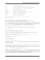
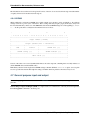
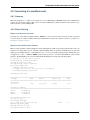
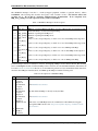
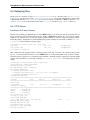
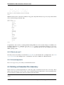
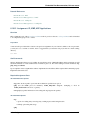
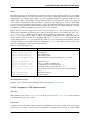
Shell commands
To print the ARP table, run the arp command from the XINU shell:
xsh@supervoc$ arp
Address
192.168.6.10
192.168.6.101
192.168.6.130
HWaddress
52:54:03:02:B1:06
00:16:B6:28:7D:4F
00:25:9C:3A:87:53
Interface
ETH0
ETH0
ETH0
Currently there is no way to add/remove entries or clear the ARP table manually.
Resources
• RFC826
3.8.3 Routing
As part of its Networking subsystem, XINU supports IPv4 routing.
At the center of the routing module is the routing daemon, which repeatedly retrieves packets from a mailbox on
which packets can be placed using rtRecv() and routes them to their destinations (or sends special packets such as
ICMP unreachable packets) by calling rtSend(). To route packets, the routing daemon makes use of a routing table.
Routing table entries can be programatically added and removed with rtAdd() and rtRemove(), respectively. The shell
command route relies on both these functions.
Add a Route
To add a route to the route entry table use route add with the following parameters:
route add <destination> <gateway> <mask> <interface>
22
Chapter 3. Components and Features (platform independent)
Embedded Xinu Documentation, Release master
Example:
route add 192.168.6.0 192.168.1.100 255.255.255.0 ETH0
Relevant source code: xsh_route(), rtAdd()
Delete a Route
To delete a route from the route entry table, use route del with the destination as the third parameter:
route del <destination>
Example:
route del 192.168.6.0
Relevant source code: xsh_route(), rtRemove().
Debugging
The routing subsystem contains Trace statements for debugging. To enable, uncomment the following line in include/route.h, and optionally change the device (such as TTY1) to which messages will be logged:
// #define TRACE_RT TTY1
3.8.4 ICMP
As part of its Networking subsystem, XINU supports the Internet Control Message Protocol (ICMP). The support
can be found in the network/icmp/ directory. This module features an ICMP daemon that runs on start up and responds
to ICMP echo requests(pings). The module implements the function icmpEchoRequest(), which is used by the ping
shell command to send ICMP echo requests to the specified IPv4 address.
Note that order to either send or reply to ICMP echo packets, the network interface needs to be brought up (e.g. by
using the netup at the shell).
Resources
• RFC792
3.8.5 TCP
XINU supports the Transmission Control Protocol (TCP). The support can be found in the device/tcp/ directory.
Note that this is not in the network/ directory; this is because the TCP module is designed to provide TCP devices
that can be controlled using the generic XINU device functions such as open(), control(), read(), write(),
close().
• Debugging
• Example - TCP Echo Test
– About
– Usage
• xsh_echotest.c
• Resources
3.8. Networking
23
Embedded Xinu Documentation, Release master
Debugging
The TCP module contains Trace statements for debugging. To enable, uncomment the following line in include/tcp.h,
and optionally change the device (such as TTY1) to which messages will be logged:
// #define TRACE_TCP
TTY1
Example - TCP Echo Test
About
This is a simple TCP usage example. It is an echo test client that sends a message to the echo server and then prints
out the reply. The echo protocol is defined in RFC 862. In short, we send a message to the server, and the server echos
the exact same message back.
Usage
• Add the source file as shell/xsh_echotest.c.
• Modify shell/shell.c and include/shell.h to include the echotest command.
• Modify shell/Makerules to include xsh_echotest.c and then make XINU from the compile directory
• Boot XINU
• Run netup command from the shell
• Run echoclient from the shell with the arguments of the echoserver’s IP address and the message to be sent in
quotes, for example:
echoclient 192.168.6.102 "Hello XINU World!"
xsh_echotest.c
#include
#include
#include
#include
#include
#include
<stddef.h>
<stdio.h>
<device.h>
<ether.h>
<tcp.h>
<string.h>
#define MSG_MAX_LEN 64
#define ECHO_PORT 7
/**
* Shell command (echotest) sends a message to an echo server per RFC 862.
* It waits for a response, then prints out the reply from the echo server.
* Expects args: echotest, echo server ip, Message to echo in quotes
* @param nargs number of arguments in args array
* @param args array of arguments
* @return non-zero value on error
*/
shellcmd xsh_echotest(int nargs, char *args[])
{
ushort dev = 0;
char buf[MSG_MAX_LEN + 1];
24
Chapter 3. Components and Features (platform independent)
Embedded Xinu Documentation, Release master
char *dest = args[1];
struct netaddr dst;
struct netaddr *localhost;
struct netif *interface;
int len;
/* Allocate a new TCP device */
if ((ushort)SYSERR == (dev = tcpAlloc()))
{
fprintf(stderr, "Client: Failed to allocate a TCP device.");
return SYSERR;
}
/* Look up local ip info */
interface = netLookup((ethertab[0].dev)->num);
if (NULL == interface)
{
fprintf(stderr, "Client: No network interface found\r\n");
return SYSERR;
}
localhost = &(interface->ip);
/* Change the destination to ipv4 */
if (SYSERR == dot2ipv4(dest, &dst))
{
fprintf(stderr, "Client: Failed to convert ip address.");
return SYSERR;
}
/* Open the TCP device with the destination and echo port*/
if (SYSERR == open(dev, localhost, &dst, NULL, ECHO_PORT, TCP_ACTIVE))
{
fprintf(stderr, "Client: Could not open the TCP device\r\n");
return SYSERR;
}
/* Send the message to the destination*/
memcpy(buf, args[2], MSG_MAX_LEN);
if(SYSERR == write(dev, buf, MSG_MAX_LEN))
{
fprintf(stderr, "Client: Error writing packet to the network");
close(dev);
return SYSERR;
}
/* Read a response from the server */
if(SYSERR != (len = read(dev, buf, MSG_MAX_LEN)))
{
/* Manual null termination needed in case of bad/malicious response
buf[len] = ’\0’;
printf("Client: Got response - %s\r\n", buf);
}
*/
/* Close the device when done */
close(dev);
3.8. Networking
25
Embedded Xinu Documentation, Release master
return 0;
}
Resources
• Transmission Control Protocol - Wikipedia
• RFC793
3.8.6 UDP
XINU supports the User Datagram Protocol (UDP). The support can be found in the device/udp/ directory. Note that
this is not in the network/ directory; this is because the UDP module is designed to provide UDP devices that can be
controlled using the generic XINU device functions such as open(), control(), read(), write(), close().
• Debugging
• Example (TFTP client)
• Example (client + server)
– About
– Usage
– xsh_udpclient.c
– xsh_udpserver.c
• Resources
Debugging
The UDP module contains Trace statements for debugging. To enable, uncomment the following line in include/udp.h,
and optionally change the device (such as TTY1) to which messages will be logged:
// #define TRACE_UDP
TTY1
Example (TFTP client)
See network/tftp/tftpGet.c. This supports a real protocol (TFTP GET), although there are some complications in the
code.
Example (client + server)
About
This is a simple example of how to use the UDP networking features in XINU (version 2.0 and later).
Usage
• Add the both of the files to the shell directory as xsh_udpclient.c and xsh_udpserver.c.
• Modify system/shell.c and include/shell.h to include the udpclient and udpserver commands.
26
Chapter 3. Components and Features (platform independent)
Embedded Xinu Documentation, Release master
• Modify shell/Makerules to include xsh_udpclient.c and xsh_udpserver.c, then make XINU
from the compile directory
• Boot two separate XINU consoles
• Run netup from the shell on both consoles
• Run udpserver from the shell on the first console
• Run udpclient from the shell on the second console with the arguments of the udpserver’s ip and the message
to be sent in quotes, for example:
udpclient 192.168.6.102 "Hello XINU World!"
xsh_udpclient.c
#include
#include
#include
#include
#include
#include
<stddef.h>
<stdio.h>
<device.h>
<ether.h>
<udp.h>
<string.h>
#define MSG_MAX_LEN 64
#define ECHO_PORT 9989
/**
* Shell command (udpclient) runs a client that sends an ASCII
* message over the network to a server using UDP.
* Expects arg0 to be echoclient, args1 to be the destination IP
address, args2 to be the message in quotes
* @param nargs number of arguments in args array
* @param args array of arguments
* @return non-zero value on error
*/
shellcmd xsh_udpclient(int nargs, char *args[])
{
ushort dev = 0;
char buf[MSG_MAX_LEN];
char *dest = args[1];
struct netaddr dst;
struct netaddr *localhost;
struct netif *interface;
/* Allocate a new UDP device */
if ((ushort)SYSERR == (dev = udpAlloc()))
{
fprintf(stderr, "Client: Failed to allocate a UDP device.");
return SYSERR;
}
/* Look up local ip info */
interface = netLookup((ethertab[0].dev)->num);
if (NULL == interface)
{
3.8. Networking
27
Embedded Xinu Documentation, Release master
fprintf(stderr, "Client: No network interface found\r\n");
return SYSERR;
}
localhost = &(interface->ip);
/* Change the destination to ipv4 */
if (SYSERR == dot2ipv4(dest, &dst))
{
fprintf(stderr, "Client: Failed to convert ip address.");
return SYSERR;
}
/* Open the UDP device with the destination and echo port*/
if (SYSERR == open(dev, localhost, &dst, NULL, ECHO_PORT))
{
fprintf(stderr, "Client: Could not open the UDP device\r\n");
return SYSERR;
}
/* Send the message to the destination*/
memcpy(buf, args[2], MSG_MAX_LEN);
if(SYSERR == write(dev, buf, MSG_MAX_LEN))
{
close(dev);
return SYSERR;
}
/* Closee the device when done */
close(dev);
return 0;
}
xsh_udpserver.c
#include
#include
#include
#include
#include
#include
#include
<stddef.h>
<stdio.h>
<device.h>
<udp.h>
<stdlib.h>
<ether.h>
<string.h>
#define ECHO_PORT 9989
/**
* Shell command (udpserver) runs a UDP server that waits for an
* incoming message, and then prints it out. Does not expect any
* arguments.
* @param nargs number of arguments in args array
* @param args array of arguments
* @return non-zero value on error
*/
shellcmd xsh_echoserver(int nargs, char *args[])
{
28
Chapter 3. Components and Features (platform independent)
Embedded Xinu Documentation, Release master
ushort dev = 0;
int len = 0;
char buffer[UDP_MAX_DATALEN];
struct netaddr *localhost;
struct netif *interface;
struct udpPseudoHdr *pseudo;
struct udpPkt *udp;
/* Allocate a new UDP device */
if ((ushort)SYSERR == (dev = udpAlloc()))
{
fprintf(stderr, "Server: Failed to allocate a UDP device.\r\n");
return SYSERR;
}
/* Look up local ip info */
interface = netLookup((ethertab[0].dev)->num);
if (NULL == interface)
{
fprintf(stderr, "Server: No network interface found\r\n");
return SYSERR;
}
/* Open the UDP device using localhost and the echo port to listen to*/
localhost = &(interface->ip);
if (SYSERR == open(dev, localhost, NULL, ECHO_PORT, NULL))
{
fprintf(stderr, "Server: Could not open the UDP device\r\n");
return SYSERR;
}
/* Set the UDP device to passive mode */
if (SYSERR == control(dev, UDP_CTRL_SETFLAG, UDP_FLAG_PASSIVE, NULL))
{
kprintf("Server: Could not set UDP device to passive mode\r\n");
close(dev);
return SYSERR;
}
/* Read lop, wait for a new request */
printf("Server: Waiting for message\r\n");
while (SYSERR != (len = read(dev, buffer, UDP_MAX_DATALEN)))
{
pseudo = (struct udpPseudoHdr *)buffer;
udp = (struct udpPkt *)(pseudo + 1);
printf("Server: Received Message - %s\r\n", udp->data);
}
close(dev);
3.8. Networking
29
Embedded Xinu Documentation, Release master
return 0;
}
Resources
• User Datagram Protocol - Wikipedia
• RFC768
3.8.7 DHCP
DHCP (Dynamic Host Configuration Protocol) support has been added to XINU as part of its networking subsystem.
Currently, only IPv4 client support— that is, acquiring IPv4 address information— is supported. The code is located
in network/dhcpc, and the API is declared in include/dhcpc.h.
In addition to basic IPv4 information (assigned IPv4 address, netmask, and gateway) the DHCP client returns the
“bootfile” and “next-server” options if they are provided by the DHCP server. If specified, this information can be
used to download the boot file using XINU’s TFTP client.
Note: This page refers specifically to the DHCP client support built into XINU, which is completely separate from
the DHCP support included in CFE, which is third-party firmware.
Resources
• Dynamic Host Configuration Protocol - Wikipedia
• RFC2131
3.8.8 TFTP
TFTP (Trivial File Transfer Protocol) support has been added to XINU as part of its networking subsystem. Currently, only client support has been implemented, and even then only TFTP Get requests are supported. (That is,
downloading files is supported but uploading files is not.) The API is declared in include/tftp.h and includes tftpGet()
and tftpGetIntoBuffer(). See the API documentation for more information.
Note that this page refers specifically to the TFTP client support built into XINU, which is completely separate from
the TFTP support included in CFE on the various MIPS-based routers, which is third-party firmware.
include/tftp.h also includes several compile-time parameters and a trace macro that can be enabled for the TFTP code.
Resources
• Trivial File Transfer Protocol - Wikipedia
• RFC1350
30
Chapter 3. Components and Features (platform independent)
Embedded Xinu Documentation, Release master
3.9 USB
USB (Universal Serial Bus) is a standard for connecting devices to a computer system. It supports an immense range
of devices, including (but not limited to) keyboards, mice, flash drives, microphones, and network adapters.
Although USB is ubiquitous in modern computer systems, even in some “embedded” devices, it is very challenging
to implement software support for USB. This is primarily a result of the high complexity of USB, which arises from
several factors, including support for virtually any arbitrary device, support for dynamic device attachment and detachment, backwards compatibility with multiple versions of the USB specification, and multiple supported speeds
and transfer types. The USB 2.0 specification is 650 pages long, yet only covers a fraction of the information needed
to implement, from scratch, a USB software stack and a driver controlling a specific USB device.
Due to the high complexity of USB, this article cannot fully explain USB, nor can it even fully explain Embedded
Xinu’s implementation of USB. Instead, it gives an overview of USB in the context of Embedded Xinu’s implementation. For full details about USB, the reader will inevitably need to read the USB specification itself, as well as other
relevant specifications and webpages. For full details specifically about Embedded Xinu’s implementation, the reader
will inevitably need to read the source code.
• General USB Information
– Bus Topology
– Devices
– Host Controllers
– Transfers
– Speeds
• Embedded Xinu’s USB subsystem
– Components
– Enabling Embedded Xinu’s USB Support
– USB for embedded systems
– USB-related shell commands
– How to write a USB device driver
– How to write a USB host controller driver
• Further reading
3.9.1 General USB Information
Bus Topology
Fundamentally, USB is just a way to connect devices to a computer system. A USB bus accomplishes this by arranging
devices in a tree. Each node of the tree is a USB device. There are two fundamental types of USB devices: hubs and
functions. USB hubs can have “child” devices in the tree, while functions cannot. Hubs can be “children” of other
hubs, up to a depth of 7 levels.
The root node of the tree is the root hub, and every USB bus has one (although it may be faked by the Host Controller
Driver, described later).
A USB hub provides a fixed number of attachment points for additional devices called ports. A USB port may be
either completely internal or exposed to the “outside” as a place to plug in a USB cable. From the user’s point of view
there is certainly a difference between these two manifestations of a USB port, but from the software’s point of view
there is no difference. On a similar note, it is also possible that a single physical package, which a naive user might
refer to as a “USB device”, actually contains an integrated USB hub onto which one or more USB devices (as defined
above) are attached. Such physical packages are referred to as compound devices. An example of a compound device
is one of Apple’s USB keyboards that provides a USB port to attach a mouse.
3.9. USB
31
Embedded Xinu Documentation, Release master
Since USB is a dynamic bus, USB devices can be attached or detached from the USB at any arbitrary time. Detaching
a hub implies detaching all child devices.
For its part, Embedded Xinu’s USB implementation fully supports the dynamic tree topology of a USB bus.
Devices
Due to the generality of USB a USB device that is not a hub can be virtually anything at all. This is made possible in
part by a highly nested design:
• A USB device has one or more configurations.
• A configuration has one or more interfaces.
• An interface has one or more alternate settings.
• An alternate setting has one or more endpoints.
Every device, configuration, interface, and endpoint has a corresponding descriptor that can be read by the USB
software to retrieve information about the described entity in a standard format.
Although this format allows for highly complex devices, most devices are relatively simple and have just one configuration. Furthermore, common devices only have one interface. In fact, as of this writing, Embedded Xinu’s USB
subsystem aims to support the common case only; it therefore always sets the device to its first listed configuration,
then attempts to bind a device driver to the entire device rather than examining individual interfaces to see if they need
separate “interface drivers”.
Host Controllers
USB is a polled bus, so all transfers over the USB are initiated by the host. The term “host” in this context means
the USB software as well as the USB Host Controller, which is the hardware responsible for actually sending and
receiving data over the USB and maintaining the root hub. This is actually one of the trickier parts of USB. Since the
USB specification itself does not standardize the exact division of tasks between software and hardware, it’s often not
clear who is responsible when the specification says “host”.
The essential thing to know is that the place where the USB software directly meets the USB hardware is in the
USB Host Controller Driver, which operates the USB Host Controller. Some USB Host Controllers present standard
interfaces (such as UHCI, OHCI, or EHCI— all defined in specifications separate from the USB specification itself)
to software. Others do not present a standard interface, but instead have vendor-provided documentation and/or a
vendor-provided driver; an example of this is the Synopsys DesignWare High Speed USB 2.0 On The Go Controller
used on the Raspberry Pi. Obviously, a standard interface is highly preferred when independently implementing a
Host Controller Driver.
Transfers
To communicate with USB devices, the host sends and receives data over the USB using USB transfers. A USB
transfer occurs to or from a particular endpoint on a particular device. Every endpoint is associated with a specific
type of USB transfer, which can be one of the following:
• Control transfers. These are typically used for device configuration. There are two main unique features of
these transfers. First, a special packet called SETUP is always sent over the USB before the actual data of the
control transfer, and software needs to specify the contents of this packet. Second, every device has an endpoint
over which control transfers in either direction can be made, and this endpoint is never explicitly listed in the
endpoint descriptors.
• Interrupt transfers. These are used for time-bounded transmission of small quantities of data (e.g. data from a
keyboard or mouse).
32
Chapter 3. Components and Features (platform independent)
Embedded Xinu Documentation, Release master
• Bulk transfers. These are used for reliable (with error detection) transmission of large quantities of data with no
particular time guarantees (e.g. reading and writing data on mass storage devices).
• Isochronous transfers. These are used for regular transmission of data with no error detecting (e.g. video
capture).
Embedded Xinu currently supports control, interrupt, and bulk transfers. Isochronous transfers have not yet been
tested. Although currently functional, interrupt transfers may require some more work to guarantee, in all cases, the
time-bounded transmission required by the USB specification.
Speeds
USB supports multiple transfer speeds:
• 1.5 Mbit/s (Low Speed) (USB 1+)
• 12 Mbit/s (Full Speed) (USB 1+)
• 480 Mbit/s (High Speed) (USB 2.0+)
• 5000 Mbit/s (Super Speed) (USB 3.0+)
Yes, Full Speed is in fact the second lowest speed. Well I think we all know that 12 Mbit/s ought to be enough for
anyone. But anyway, due to the need to maintain backwards compatibility with legacy devices, the USB software
(mainly the host controller driver) unfortunately needs to take into account transfer speeds. At minimum, it must
be aware that transfers to or from devices attached at Low Speed or Full Speed are performed as a series of split
transactions, which allow Low Speed or Full Speed transfers to occur without significantly slowing down the portion
of the USB bus operating at a higher speed.
As of this writing, Embedded Xinu’s USB subsystem supports USB 2.0, so it supports devices operating at Low Speed,
Full Speed, or High Speed. USB 3.0 Super Speed is not supported.
3.9.2 Embedded Xinu’s USB subsystem
Now that some general information about USB has been presented, it should be easier to understand the basic design
of a USB software stack. The description that follows is certainly not the only way to organize the code, but it is the
way that is used in most operating systems and makes the most sense based on how USB was designed. In terms of
Embedded Xinu, perhaps the main question is why USB devices and/or the USB controller do not, by default, show up
as device(s) in devtab like other Embedded Xinu devices. The reasons are that USB is a dynamic bus, so it cannot be
described by a static table, and also because the highly nested structure of USB devices, as well as multiple supported
transfer types, is too complicated for the simple “read() and write() from a device” paradigm.
Note: Specific USB device drivers can still provide device entries in devtab if needed. However, they must account
for the fact that the physical devices are still hot-pluggable.
Note: Not all Embedded Xinu platforms support USB, either due to not having USB hardware available or not having
an appropriate USB host controller driver implemented.
Components
• The USB Host Controller Driver is responsible for actually sending and receiving data over the USB by making
use of the platform-dependent host controller hardware. The purpose of this driver is to isolate differences in
USB host controllers from all other code dealing with USB. In Embedded Xinu, USB Host Controller Drivers
must implement the interface declared in include/usb_hcdi.h. (However, as of this writing, there is only one
3.9. USB
33
Embedded Xinu Documentation, Release master
Host USB Controller Driver implemented and it controls the Synopsys DesignWare High Speed USB 2.0 On The
Go Controller used on the Raspberry Pi.)
• The USB Core Driver is responsible for maintaining the USB device model, including the tree structure, and
providing a framework in which USB device drivers can be written. It provides many convenience functions
that simplify USB device driver development over using the Host Controller Driver directly; this can be viewed
as an attempt to isolate the platform-dependent Host Controller Driver as much as possible. It also handles
configuration that is common to all USB devices, such as setting a device configuration and address, and reading
descriptors. In Embedded Xinu, the USB Core Driver can be found in device/usb/usbcore.c.
• USB device drivers are responsible for controlling specific USB devices. Since USB is a dynamic bus, USB
device drivers are bound to actual USB devices at runtime with the help of USB Core Driver. A very important
USB device driver that must always be implemented in any USB software stack is the USB hub driver, which
is responsible for monitoring the status of a USB hub and reporting to the USB Core Driver when devices have
been attached or detached. Embedded Xinu’s USB hub driver can be found in device/usb/usbhub.c. Other USB
device drivers can be found in device/; e.g. device/smsc9512/.
Note: More complete (and complicated) USB software stacks, such as Linux’s, also support USB interface drivers,
which are associated with USB interfaces rather than USB devices.
Enabling Embedded Xinu’s USB Support
To include support for USB in a given build of Embedded Xinu, define WITH_USB in xinu.conf and add usb
to the DEVICES variable in platformVars. Note that the USB hub driver will be included automatically as it is
required for USB to support any devices whatsoever.
In addition, you need to ensure that an appropriate Host Controller Driver, which is platform-dependent code and is
not located in this directory, has been written and is compiled into the kernel. For example, system/platforms/armrpi/usb_dwc_hcd.c is the Host Controller Driver that is used on the Raspberry Pi hardware.
Finally, you need to enable any actual USB devices you want to support by adding the corresponding device directories
to the DEVICES variable in platformVars, then defining the appropriate static devices in xinu.conf. For
example, on the Raspberry Pi, we enable the driver for the SMSC LAN9512 USB Ethernet Adapter, which is located
in device/smsc9512, by adding smsc9512 to DEVICES and defining the ETH0 device in xinu.conf.
USB for embedded systems
For fully embedded systems where debugging facilities are not critical, unnecessary human-friendly functionality can
be omitted from the USB core. See device/usb/usbdebug.c for more details.
USB-related shell commands
The usbinfo shell command prints out information about devices attached to the USB. See shell/xsh_usbinfo.c for
more details, or run usbinfo --help.
How to write a USB device driver
You first of all must acquire any available documentation for the USB device. Note that many devices do not have their
own documentation because they conform to one of the USB class specifications; in such cases the documentation is
the class specification, even though these are typically fairly long and complicated.
34
Chapter 3. Components and Features (platform independent)
Embedded Xinu Documentation, Release master
For nonstandard devices with no documentation available, you will have to use whatever means are available to you
for understanding the device protocol, such as source code for other operating systems. As a last resort, the software
interface to a USB device can be reverse-engineered by snooping on USB traffic generated by binary drivers.
Either way, to write the driver you will need to understand the format and meaning of messages sent to and from the
device, and which USB endpoints and transfer types they are associated with.
Examples:
• USB Human Interface Devices such as mice are required to have an IN interrupt endpoint which is used to report
input data such as mouse coordinates, and certain metadata can be queried from the default control endpoint.
• USB networking devices, such as the SMSC LAN9512, provide a bulk IN endpoint for receiving networking
packets and a bulk OUT endpoint for sending network packets.
On to the code itself: In Embedded Xinu, USB device drivers are implemented using the API provided by the USB
Core Driver, which is declared in usb_core_driver.h. This API allows drivers to register themselves, bind themselves
to USB devices that are detected by the core, and communicate with USB devices. It is documented fairly extensively
in the source; also see device/smsc9512/ for an example of a USB device driver.
Note that Xinu’s static device model is incompatible with USB’s dynamic device model, which is something that needs
to be worked around by the USB device drivers. For example, the driver might refuse to bind itself to more than a
fixed number of USB devices, and it might block or return failure if code tries to open the static device before it has
actually been bound to an actual USB device.
How to write a USB host controller driver
In Embedded Xinu, the USB Host Controller Driver is responsible for actually interacting with the hardware (the USB
Host Controller) to send and receive data over the USB. Unfortunately, USB Host Controllers are not standardized by
the USB specification itself, which is why this abstraction layer is needed. USB Host Controllers include those compliant with the UHCI, OHCI, or EHCI specifications, as well as nonstandard ones such as the Synopsys DesignWare
High Speed USB 2.0 On The Go Controller used on the Raspberry Pi.
The very first step is to determine whether Xinu already supports the USB Host Controller for the hardware under
consideration. If so, you can use that code, but some changes may be needed (e.g. the location of memory-mapped
registers). Otherwise, read on....
The USB Host Controller Driver must implement the interface declared in include/usb_hcdi.h.
You first must acquire any documentation (if it exists) for the Host Controller. You also need to read relevant parts of
the USB 2.0 Specification, mainly those that describe control, interrupt, and bulk transfers. Most of the 650 pages you
do not need to read.
Next, in hcd_start(), you must write any code that is needed to prepare the Host Controller to be ready to use.
The next and essentially final step is to implement hcd_submit_xfer_request(), which is very difficult. You
should initially focus on faking requests that are sent to the root hub. These will include various control transfers to and
from the root hub’s default endpoint as well as an interrupt transfer from the root hub’s status change endpoint. Some
root hub requests can be handled entirely in software; others will need to communicate with the Host Controller. Next,
you must support control transfers to and from actual USB devices on the bus. Finally, you must support interrupt
and bulk transfers. These must be asynchronous and interrupt-driven. Note that the hub driver uses interrupt transfers
in order to detect port status changes; thus, it will be impossible to enumerate the entire USB until interrupt transfers
have been implemented.
You can use the usb_debug() and usb_dev_debug() macros to print debugging messages. Enable them by
changing the logging priorities in include/usb_util.h.
3.9. USB
35
Embedded Xinu Documentation, Release master
3.9.3 Further reading
• USB 2.0 Specification
• USB 3.1 Specification
• Embedded Xinu USB 2.0 subsystem. (device/usb)
• Embedded Xinu USB device drivers. (Example: device/smsc9512/)
• Embedded Xinu USB host controller drivers. (Example: system/platforms/arm-rpi/usb_dwc_hcd.c)
3.10 USB keyboard driver
Support for USB (Universal Serial Bus) keyboards has been added to Embedded Xinu via the usbkbd device driver,
located in device/usbkbd/.
The usbkbd driver is a USB device driver and can only be built when Embedded Xinu’s USB support has been enabled.
3.10.1 External interface
Like other Embedded Xinu device drivers such as the various UART drivers, the usbkbd driver provides one or more
device table entries, such as USBKBD0, USBKBD1, etc. Characters can be read from these devices simply by using
getc() or read() on these devices. These functions will block if the corresponding USB keyboard is detached or has yet
to be attached.
3.10.2 Scope
The usbkbd driver only supports the keyboard boot protocol defined in the USB HID (Human Interface Device)
specification. This protocol defines a fixed 8-byte report that the keyboard provides over its IN interrupt endpoint
when a key is pressed or released. usbkbd does not parse the HID report descriptor and does not support any other
Human Interface Devices, such as mice (or steering wheels, or data gloves...).
Since data is provided by usbkbd as 8-bit characters, there is limited support for special keys that do not correspond to
printing characters, and currently most are simply ignored.
3.10.3 Implementation details
When sysinit() runs, init() is called on each device table entry, resulting in a call to usbKbdInit() for each keyboard
device entry. As soon as one of these calls occurs, usbkbd registers itself with the USB subsystem as a USB device
driver. usbKbdInit() does not wait for a keyboard to actually be attached before returning.
When a USB device is attached, usbKbdBindDevice() is called by the USB subsystem. If the device has a HID interface
supporting the keyboard boot protocol (i.e. “is a USB keyboard”), a recurring USB transfer from the keyboard’s IN
interrupt endpoint is started. When each such transfer completes, usbKbdInterrupt() is called by the USB subsystem,
and any new characters detected are placed in a buffer for later retrieval by reads from the keyboard device.
3.10.4 See also
• USB
• How to write a USB device driver
• TTY driver
36
Chapter 3. Components and Features (platform independent)
Embedded Xinu Documentation, Release master
3.10.5 References
• Universal Serial Bus (USB) Device Class Definition for Human Interface Devices (HID), Version 1.11
• Universal Serial Bus (USB) HID Usage Tables, Version 1.11
3.10. USB keyboard driver
37
Embedded Xinu Documentation, Release master
38
Chapter 3. Components and Features (platform independent)
CHAPTER 4
MIPS ports (including Linksys routers)
4.1 Common Firmware Environment
4.1.1 About
The Common Firmware Environment (CFE) is the firmware developed by Broadcom for the BCM947xx SoC
platform (among others). It is the first code that runs when the router boots and performs functions similar to Apple’s
Open Firmware:
• Initializes the system
• Sets up a basic environment in which code can run
• Optionally provides a command line interface non-standard usage
• Loads and executes a kernel image (expecting to be jettisoned shortly thereafter)
So, in normal operation, a user will not see CFE working at all; it will load the Linksys kernel and send it on its merry
way without hesitation. For us, however, CFE is crucial, because it provides us with the ability to load an image over
the network using TFTP.
We have access to two major documents covering CFE, the reference manual, and the functional specification. Much
of the content in these two documents overlaps.
4.1.2 Getting into CFE
To get into CFE, it will be very helpful to enable “boot wait” from the Administration Tab under the router’s Web GUI.
This will cause the router to wait on startup for a signal to stop booting into the firmware and enter CFE.
Once you have that set up and you’ve connected to the router, just type “reboot” (assuming OpenWRT is installed, it
may be different for other firmwares) to reboot the router. This can also be done by power-cycling the router. As it’s
booting up, send a continuous stream of Ctrl+C characters to cancel booting and you’ll be entered right into CFE.
From there, you can prod around CFE’s features or load your own kernel using the command line interface.
4.1.3 Command Line Interface
The CFE Command Line Interface (CLI) is a very simple “shell-like” command prompt. It has a few environmental
variables and minimal functionality. However, it is complex enough power to load a boot image over the network and
begin executing code. The User interface is described on page 19 of 145 in the CFE documentation.
39
Embedded Xinu Documentation, Release master
To get the to the CLI, you can use either the power-on method or load OpenWRT and type reboot. The CFE boot
screen looks like:
CFE version 1.0.37 for BCM947XX (32bit,SP,LE)
Build Date: Fri Sep 23 17:46:42 CST 2005 ([email protected])
Copyright (C) 2000,2001,2002,2003 Broadcom Corporation.
Initializing Arena
Initializing Devices.
No DPN
et0: Broadcom BCM47xx 10/100 Mbps Ethernet Controller 3.90.37.0
CPU type 0x29008: 200MHz
Total memory: 16384 KBytes
Total memory used by CFE:
Initialized Data:
BSS Area:
Local Heap:
Stack Area:
Text (code) segment:
Boot area (physical):
Relocation Factor:
0x80300000
0x803398D0
0x8033BFE0
0x8033D9C0
0x803A19C0
0x80300000
0x003A4000
I:00000000
-
0x803A39C0
0x8033BFE0
0x8033D9C0
0x803A19C0
0x803A39C0
0x803398D0
0x003E4000
D:00000000
(670144)
(10000)
(6624)
(409600)
(8192)
(235728)
Boot version: v3.7
The boot is CFE
mac_init(): Find mac [00:16:B6:28:7D:4F] in location 0
Nothing...
eou_key_init(): Find key pair in location 0
The eou device id is same
The eou public key is same
The eou private key is same
Device eth0: hwaddr 00-16-B6-28-7D-4F, ipaddr 192.168.1.1, mask 255.255.255.0
gateway not set, nameserver not set
Reading :: Failed.: Interrupted
CFE> ^C
CFE>
Of course, items like the hwaddr will be different from router to router.
Once you have a command prompt, you can type help and get a listing of commands available:
CFE> help
Available commands:
rndis
et
modify
nvram
reboot
flash
memtest
f
e
d
u
autoboot
batch
40
Broadcom USB RNDIS utility.
Broadcom Ethernet utility.
Modify flash data.
NVRAM utility.
Reboot.
Update a flash memory device
Test memory.
Fill contents of memory.
Modify contents of memory.
Dump memory.
Disassemble instructions.
Automatic system bootstrap.
Load a batch file into memory and execute it
Chapter 4. MIPS ports (including Linksys routers)
Embedded Xinu Documentation, Release master
go
boot
load
save
ping
arp
ifconfig
show devices
unsetenv
printenv
setenv
help
Verify and boot OS image.
Load an executable file into memory and execute it
Load an executable file into memory without executing it
Save a region of memory to a remote file via TFTP
Ping a remote IP host.
Display or modify the ARP Table
Configure the Ethernet interface
Display information about the installed devices.
Delete an environment variable.
Display the environment variables
Set an environment variable.
Obtain help for CFE commands
For more information about a command, enter ’help command-name’
*** command status = 0
CFE>
A command status of 0 is always a good thing, other command statuses are errors.
The next two commands are very important to booting a custon kernel image: ifconfig and boot.
ifconfig is just the Linux counterpart, it will set up the specified interface. For our router, we have the switch
portion of the router connected to a xinu server (which is simply a TFTP and DHCP server). From there we type
ifconfig -auto eth0 which will ask the xinu server for an IP address and set up the router.
CFE> ifconfig -auto eth0
Device eth0: hwaddr 00-16-B6-28-7D-4F, ipaddr 192.168.5.2, mask 255.255.254.0
gateway 192.168.5.220, nameserver 192.168.5.220, domain xinu.mu.edu
*** command status = 0
CFE>
We now have an IP address and can transfer our boot image.
For our purposes, we name our boot images after the unit on which it will load (supervoc is our demo router).
CFE> boot -elf 192.168.5.220:supervoc.boot
Loader:elf Filesys:tftp Dev:eth0 File:192.168.5.220:supervoc.boot Options:(null)
Loading: 0x80001000/3145 0x80001c49/23 Entry at 0x80001000
Closing network.
Starting program at 0x80001000
Let’s walk through these lines:
boot -elf 192.168.5.220:supervoc.boot
This will begin booting the supervoc.boot kernel that is located at 192.168.5.220 (our xinu server and, no, name
resolution does not work).
Loader:elf Filesys:tftp Dev:eth0 File:192.168.5.220:supervoc.boot Options:(null)
A fairly explanatory line stating the file type it is loading (elf), the file system to be used (tftp), the device which
it is using to transfer the image (eth0), and where that image is from (192.168.5.220:supervoc.boot).
Loading: 0x80001000/3145 0x80001c49/23 Entry at 0x80001000
This is also a line of explanation. The first portion (0x80001000/3145) tells us the ‘physical’ address of where
we begin loading our image and the size of the image (in bytes). Next is the address of the end of the image
(0x80001c49/23) and (I believe) the amount of padding to make the image size base 16. The last part is the
address which CFE will branch to upon completion of upload, this is the start of your kernel.
4.1. Common Firmware Environment
41
Embedded Xinu Documentation, Release master
Closing network.
Starting program at 0x80001000
The closes the network and begins execution the code at address 0x8000100. Any lines of text outputted after this
are from your boot image (unless CFE throws an exception and shows a memory dump).
4.2 EJTAG
EJTAG is a MIPS-specific extension of IEEE 1149.1, the Joint Test Action Group. Allows interfacing with additional
logic in SoC
• direct control of processor for step-by-step debugging
• access to busses and registers
– aids in debugging
– possible usage as additional peripheral data bus
– direct writing to flash for firmware updates (and de-bricking)
4.2.1 Debugging
Attempting to use GNU debugger: http://www.gnu.org/software/gdb. GDB uses its own Remote Serial Protocol
(RDB) to communicate to remote targets. This protocol could be used to communicate with the XINU backends
through the current serial connection. Although, this would require additions to XINU: communication with the GDB
host; altering of exception handler to allow GDB to take control of target processor.
The use of the EJTAG port on the WRT54-series routers gives the user hardware control of the processor, avoiding
the need for strategically placed breakpoints and XINU interrupt subsystem modification. Additionally, requests by
the debugger for specicfic data can be aquired directly from registers. The trick to this operation is software that can
interpret commands from RDB into EJTAG signals to be sent through the host parallel port, and vice-versa. An implementation of this interpreter can be found at http://www.totalembedded.com/open_source/jtag/mips32_ejtag.php.
4.2.2 Specific Implementations
So far, development has focused exclusively on the WRT54GL. For anyone investigating the capabilities of the
WRT54GL EJTAG system, note the instruction register size is a full 8 bits, not the 5 bits required by specification. Believing the 54GL CP0 Debug Program Counter register to be returning erroneous addresses, headers are being
added to a 54G v.8, and a 350N v.1. For IDCODEs and implementation register values check EJTAG ID Codes and
Implementation Registers.
4.2.3 Probes
Images are of three variant EJTAG connections. The first two buffered by active line drivers, the last passive. Xinu
research is currently using an active probe similar to the OpenWRT “Wiggler” clone; although, the parallel port pinouts
match the unbuffered cable diagram. Note that the unbuffered cable at the bottom of this page is only proven by xinu
research functional in writing to the Test Access Port. It may not read data back from the target device. Additionally,
rumor claims that the cable can be no longer than 6” (not 6’). This is partially substantiated by photographs “out there”
of similar 6 inch cables used with a variety of devices.
42
Chapter 4. MIPS ports (including Linksys routers)
Embedded Xinu Documentation, Release master
Figure 4.1: Total Embedded buffered cable
4.2.4 See also
• EJTAG ID Codes and Implementation Registers
4.3 EJTAG ID Codes and Implementation Registers
When an EJTAG system is reset, the data register is automatically filled with the result of an IDCODE instruction.
This code usually includes the processor and the manufacturer, although it is not a standard. The important part of
the IDCODE is using it to determine if your host hardware is communicating with your target. Whether or not the
host speaks fluent jtag, if it can navigate to the data register and shift out the contents, one can see if the electrical
connection is sound.
IDCODEs
WT54GLv1.1 : 0x0535217F
WRT54Gv8 : 0x1535417F
WRT350Nv1.0 : 0x0478517F
The implementation code instruction returns an indication of features on the particular platform. Below is the information from the MIPS EJTAG Specification, document #MD00047.
IMPCODEs
WT54GLv1.1 : 0x00800904
WRT54Gv8 : 0x00810904
WRT350Nv1.0 : 0x00810904
4.3. EJTAG ID Codes and Implementation Registers
43
Embedded Xinu Documentation, Release master
Figure 4.2: “wiggler” clone from OpenWRT
Figure 4.3: unbuffered cable from OpenWRT; used by de-brick utility
44
Chapter 4. MIPS ports (including Linksys routers)
Embedded Xinu Documentation, Release master
Figure 4.4: Our current buffer/wiggler setup
4.3. EJTAG ID Codes and Implementation Registers
45
Embedded Xinu Documentation, Release master
46
Chapter 4. MIPS ports (including Linksys routers)
Embedded Xinu Documentation, Release master
4.4 Exception and Interrupt Handling (MIPS)
On MIPS processors, Embedded Xinu tilizes a interrupt handling system which allows components to register custom
interrupt handlers to the system at runtime or fall-back to the default trap handler.
MIPS processors will jump to and execute code beginning at 0x8000 0180 when an exception or interrupt occurs.
Code for handling traps must occupy no more than 0x20 bytes at this location (eight instructions), therefore Embedded
Xinu uses three instructions to jump to different code which will handle traps more robustly.
In order to handle exceptions (such as TLB misses) efficiently, Embedded Xinu uses an interrupt vector system to
quickly read the exception code, load the registered exception handler, and jump to the handler. If any of these steps
do not exist, the handler will fall-back to the default trap handler.
If an interrupt has occurred it is important to save the state of the processor and handle the interrupt gracefully so the
system can continue running. Thus, if the interrupt handler was called by an interrupt and not an exception, the code
will save the state of the processor and perform a similar lookup for interrupt handlers.
4.5 Flash driver
Embedded Xinu uses a multi-layered approach to dealing with Flash memory on platforms where it is available (including MIPS-based routers such as the WRT54GL). This allows the presentation of a simple and consistent interface
to user programs, while handling the more complicated hardware interface underneath.
4.5.1 High level API
Like other drivers in Embedded Xinu, the Flash driver provides user level calls to open(), close(), read(),
write(), and control(). In order to begin using a device the user must open() it, this initializes the logical
layer and sets up structures for use. The complimentary close() function will clear those structures and write any
cached data to the underlying Flash hardware.
control() provides several functions for getting information and performing operations on the driver. The control
functions are presented below.
• FLASH_BLOCK_SIZE returns the size of logical blocks for the Flash device.
• FLASH_N_BLOCKS returns the number of block available on the Flash device.
• FLASH_SYNC forces a synchronization from cached data onto Flash memory, the two forms are:
– FLASH_BLOCK synchronizes a specific erase block, and
– FLASH_LOGBLOCK synchronizes a logical block of data.
read() and write()
The Flash device takes three slightly different parameters for read() and write() when compared to other devices
in Embedded Xinu. Normal devices will take the device identifier, a buffer, and the size of the buffer. Since the Flash
device uses fixed size logical blocks, it is assumed that the buffer will be the size of a single logical block. Therefore,
the Flash driver API for read() and write() is:
read(int device_id, char *buffer, uint block_number);
write(int device_id, char *buffer, uint block_number);
4.4. Exception and Interrupt Handling (MIPS)
47
Embedded Xinu Documentation, Release master
4.5.2 Logical Layer
Normal block-oriented devices present a consistent view of data storage with each block being a small fixed size
ranging from 512 bytes to 4,096 bytes. Flash memory does not act like normal block-oriented devices though. The
underlying hardware is separated into erase block regions of which there can be four. Each erase block region can hold
a number of erase blocks of a fixed size. These fixed sizes can be any size that is a power of two. For example, on
the WRT54GL platform, Flash is separated into two erase block regions, one with 8 - 8 KB erase blocks and the other
with 63 - 64 KB erase blocks.
To avoid the user level programmer from having to deal with this inconsistent view of erase blocks, the logical layer
of the Flash driver splits all of Flash memory into uniformly sized logical blocks (at present this is 512 byte blocks).
When a call to read() occurs, the logical layer will determine what erase block the logical block maps to, determine
if the erase block has already been loaded into RAM and return a pointer to the cached data. Similarly, a call to
write() will perform a mapping from logical to erase block and write the data to the cached memory. If too many
erase blocks are stored in RAM, the logical layer will evict a block and if it has been modified since the read it will
write it back to Flash memory.
4.5.3 Physical Layer
Once the logical to erase block mapping has occurred, the logical layer can pass the erase block stored in RAM to
the physical layer to perform the low level hardware operations. At this layer, the software only deals in erase block
units and uses manufacturer specific code. Currently, Embedded Xinu fully supports the Intel Standard Command Set
(SCS) and the AMD/Samsung SCS is a work in progress.
Largely, the routines to handle the hardware follow similar concepts. When a non-read request is made to the physical
layer the software steps through a series of operations to change an erase block from read-mode to program or erase
mode. When this happens, the software is able to safely modify the data.
An interesting property of Flash memory is that certain devices allow program and erase operations to be suspended,
so it may be possible to spin the physical layer off as a separate pre-emptible process. Unfortunately, while the Intel
SCS supports suspend/resume operations the AMD/Samsung SCS does not, so this would lead to compatibility issues
if implemented.
4.5.4 NVRAM
NVRAM settings are stored in Flash memory and take advantage of both the logical and physical layers of the Flash
driver. When NVRAM is first initialized, the Flash driver determines what logical block the settings begin in and then
begins reading and storing the settings into RAM. Each tuple is indexed into a hash table and allocated a piece of
memory to store the data in. When a setting is changed, the original value is released from memory and the new value
is added. If a value is requested, the driver will simply find the storage location and return the pointer to the data.
When the updated settings are committed to Flash, the NVRAM driver will discover the logical block to erase block
mapping, create a complete erase block with the new settings, cause a write in the physical layer, and finally force a
synchronization to commit the settings to Flash.
4.6 Flash memory
Note: This page appears to have been written with WRT54GL routers in mind and may or may not be applicable to
other platforms.
Like other memory mapped hardware devices on the MIPS platform, Flash memory has an address range in KSEG1.
This means that the memory is unmapped and uncached. An interesting, and important, piece of information is that
48
Chapter 4. MIPS ports (including Linksys routers)
Embedded Xinu Documentation, Release master
all 4 megabytes of Flash memory is mapped 1-1 into the address range between 0xBC00 0000 and 0xBC3F FFFF.
This allows for random read-access without using an interface to load the data a fixed amount of registers.
4.6.1 Data Locations
Stored on Flash memory are several important parts to make a backend work properly, some of these data points are
listed below.
• 0xBC00 1000 has backup NVRAM settings. If the “proper” settings become corrupt, CFE will replace the
proper settings with these.
• 0xBC00 1E00 holds the “true” MAC address of device. During CFE boot, this is the address that will be used.
Once a full kernel has been loaded the MAC address may be different.
• 0xBC00 1F00 holds the current CFE boot version (should be “v3.7” for WRT54GLs).
• 0xBC00 2000 is the beginning of CFE code.
• 0xBC03 F400 is a unique device ID (should match the NVRAM setting for eou_device_id).
• 0xBC03 F408 is a unique private key for device (should match the NVRAM setting for
eou_private_key).
• 0xBC03 F508 is a unique public key for device (should match the NVRAM setting for eou_public_key).
• 0xBC04 0000 is the beginning of the operating system kernel (Embedded Xinu or some Linux variant). Typically, this will be a gzipped version of the raw kernel code prefixed with a TRX header.
• 0xBC3F 8000 is the location of proper NVRAM settings.
This is not a comprehensive list of memory locations within Flash memory, but a guide of where some values may be
stored when trying to interface with a new system.
4.6.2 Writing Flash
Writing data to Flash memory is not simply a matter of writing data to the memory address. For the WRT54GL
backends the common NOR type of Flash memory is used. As with all Flash memories there are certain properties
that must be followed when storing data.
An important property of NOR based Flash memory is that each bit on Flash can only be changed from a 1 to a 0 and
not the other way around. So if a byte has the pattern 1001 1101 only the high bits can be written. This presents an
interesting challenge for efficient file system structures. Once a bit has been set to 0 and the operating system wishes
to reset the bit to 1 a special erase command must be sent to the device. Because of this Flash memory is broken down
into several distinct segments called erase blocks. These erase blocks can vary in size between Flash memory chips
and even within the same chip. After sending the command to erase an erase block, the entire erase block will be set
to 1s, allowing any data to be written. The specific method of erasing and writing data depends on the manufacturer
of the underlying hardware. In general it is a matter of writing a sequence of values to a certain location to prepare the
device, then writing the new data to the correct position. These operations are more detailed on the Flash driver page
under physical layer.
4.6.3 Common Flash Interface
Luckily for software authors, the manufacturers of Flash memory have developed a standard for discovering information about a Flash device, called the Common Flash Interface (CFI). By implementing a CFI query routine, the
operating system can discover what command set the chip implements (Intel, AMD, and Mitsubishi all have a standard command set and extended command set). Other information that can be queried is voltages, timeouts for writing
and erasing, access mode (word or byte), device size (as 2𝑛 ), and information about up-to four erase block regions.
4.6. Flash memory
49
Embedded Xinu Documentation, Release master
The information about each erase block region will consist of the size of an erase block in the region and the number
of equally sized erase blocks that exist in the regions.
4.6.4 NVRAM
While technically a misnomer, NVRAM (non-volatile random access memory) refers specifically to the platform
settings stored across power cycles of the device. These settings will always begin 8 pages (32 kilobytes) away from
the end of Flash memory. In the case of the WRT54GL, this means NVRAM settings are stored beginning at 0xBC3F
8000. At this point there is a 20 byte header which is laid out as follows:
0
1
2
3
0 1 2 3 4 5 6 7 8 9 0 1 2 3 4 5 6 7 8 9 0 1 2 3 4 5 6 7 8 9 0 1
+---------------------------------------------------------------+
|
magic number (’FLSH’)
|
+---------------------------------------------------------------+
|
length (header size + variables)
|
+---------------+---------------+-------------------------------+
|
CRC
|
version
|
SDRAM Init (?)
|
+---------------+---------------+-------------------------------+
|
SDRAM config (?)
|
SDRAM refresh (?)
|
+-------------------------------+-------------------------------+
|
NCDL value (?)
|
+---------------------------------------------------------------+
Several of the values are not used by Embedded Xinu as the values represent something that is not fully understood
(all the SDRAM values and the NCDL value).
Immediately after the header begins the NVRAM settings as NULL delimited name=value tuples stored as plain
text. It is possible that after the final tuple the settings are NULL character padded to the nearest 4 byte word.
4.7 General purpose input and output
Note: This page appears to have been written with WRT54GL routers in mind and may not be applicable to other
platforms.
General Purpose Input and Output (GPIO) is a simple method of communication. Currently the shell implements
the led and gpiostat commands to use these ports.
50
Chapter 4. MIPS ports (including Linksys routers)
Embedded Xinu Documentation, Release master
4.7.1 Port Assignments
Pin
GPIO 0
GPIO 1
GPIO 2
GPIO 3
GPIO 4
GPIO 5
GPIO 6
GPIO 7
Assignment
WLAN LED
Power LED
Cisco LED White
Cisco LED Orange
Cisco Button
Unknown
Reset Button
DMZ LED
4.7.2 Registers
There are four control and status registers, each which is 2 bytes.
• Input (0xb8000060) - If a GPIO pin is set for output, its input bit is automatically set to 0.
• Output (0xb8000064) - If a GPIO pin is set for input, its output bit is automatically set to 0.
• Enable (0xb8000068) - Determines if a GPIO pin is used for input or output. A bit value of 0 is input and 1 is
output.
• Control (0xb800006c) - Usage is currently unknown.
4.7.3 LEDs
Research Notes:
• An LED is enabled by setting its enable bit to 1.
• When an LED is enabled, its input bit becomes 0.
• Once an LED is enabled, if its output bit is 0, the LED is on and if its output bit is 1, the LED is off.
4.7.4 Resources
• SD Card Reader Driver
• Adding an MMC/SD Card
4.8 Backing up your router
Note: This page appears to have been written with WRT54GL routers in mind and may or may not be applicable to
other platforms.
When experimenting with kernels, you may find yourself corrupting the router and having to recover from a known
good state. It is a good idea to make a copy of the CFE when it is in its original factory configuration for if and when.
Here are a few different methods depending on your resources:
4.8. Backing up your router
51
Embedded Xinu Documentation, Release master
4.8.1 dd-wrt
If you are running a relatively recent version of dd-wrt, you can download the CFE from the web interface.
Location: http://ROUTER_IP/backup/cfe.bin>
4.8.2 CFE
To backup the CFE from within the CFE itself you need an active serial console and a live network connection to
a TFTP server. On the TFTP server, create a file for the backup image. It must be world writable. If you do not
pre-create the file for the TFTP client, the backup may fail. We name and label our routers to keep them straight.
Consider naming the backup image after each router’s hostname if you have many of them.
Example:
user@xinuserver:tftpboot$ touch routername.cfe
user@xinuserver:tftpboot$ chmod a+w routername.cfe
Access the CFE using the usual method.
If necessary, configure the network interface and check the connection to your TFTP server (192.168.6.10 in this
example):
CFE> ifconfig eth0 -auto
Device eth0: hwaddr 00-1E-E5-86-02-7A, ipaddr 192.168.6.122, mask 255.255.255.0
gateway 192.168.6.50, nameserver 134.48.7.10, domain xinu.mu.edu
*** command status = 0
CFE> ping 192.168.6.10
192.168.6.10 (192.168.6.10) is alive
192.168.6.10 (192.168.6.10): 1 packets sent, 1 received
*** command status = 0
Save the CFE region to the file you created on the TFTP server:
CFE> save 192.168.6.10:routername.cfe BC000000 40000
262144 bytes written to 192.168.6.10:routername.cfe
*** command status = 0
Note: You can also save the entire flash image (CFE+Kernel+NVRAM) by passing 400000 as the length instead of
40000. This isn’t really necessary, but you might find it referenced elsewhere. If you have to recover via JTAG it will
take a LONG time to restore the entire flash image. It is much more efficient to load just the CFE, then upload the
kernel via TFTP and use a factory reset to restore NVRAM.
4.8.3 JTAG
For this method to work, we assume you have a working EJTAG interface to your router. For details, check out our
Recovering a router page.
Use the -probeonly option to figure out what options TJTAG needs for your particular setup.
Backup the CFE with TJTAG:
user@host:tjtag$ ./tjtag -backup:cfe /wiggler /noemw /noreset
TJTAG will create a CFE.BIN file with some sort of timestamp identifier appended to the filename. Rename and store
somewhere safe.
52
Chapter 4. MIPS ports (including Linksys routers)
Embedded Xinu Documentation, Release master
4.9 Connecting to a modified router
4.9.1 Summary
This will explain how to connect to the serial ports on a modified Linksys WRT54G using serial communication
software. In our tutorial we will use Picocom for our serial communication software because it is free and easy to get
with a front end or server running Linux.
4.9.2 Before Starting
Expose a serial port on the router
You must have successfully modified a Linksys WRT54G to expose at least its first serial port in such a way that
you can connect it to another machine with serial communications software. If you have not done so yet, please see
Modifying the Linksys hardware.
Acquire serial communication software
There is a freely available software package for serial communication on almost every major platform. Picocom is one
such piece of software that is easy to obtain on a machine running Linux. To get Picocom installed on your front end
simply open a terminal and type ‘‘ yum install picocom ‘‘ (or use your system’s package install command if it does
not support the ‘‘ yum ‘‘ command). NOTE: you may need root access to your front end machine in order to install
packages. We installed Picocom on a front end machine running Fedora 9 and got the following output:
[root@argolis ~]# yum install picocom
Loaded plugins: refresh-packagekit
Setting up Install Process
Parsing package install arguments
Resolving Dependencies
--> Running transaction check
---> Package picocom.i386 0:1.4-4.fc9 set to be updated
--> Finished Dependency Resolution
Dependencies Resolved
=============================================================================
Package
Arch
Version
Repository
Size
=============================================================================
Installing:
picocom
i386
1.4-4.fc9
fedora
29 k
Transaction Summary
=============================================================================
Install
1 Package(s)
Update
0 Package(s)
Remove
0 Package(s)
Total download size: 29 k
Is this ok [y/N]: y
Downloading Packages:
(1/1): picocom-1.4-4.fc9.i386.rpm
Running rpm_check_debug
Running Transaction Test
Finished Transaction Test
4.9. Connecting to a modified router
|
29 kB
00:00
53
Embedded Xinu Documentation, Release master
Transaction Test Succeeded
Running Transaction
Installing: picocom
######################### [1/1]
Installed: picocom.i386 0:1.4-4.fc9
Complete!
[root@argolis ~]#
Alternatively, if you are building multiple backends to be made available as a pool, our suite of XINU Console Tools
includes a basic serial console utility called tty-connect. However it is recommended that you do not use the XINU
Console Tools‘s tty-connect utility for directly connecting a single back end router to a front end machine because
this utility does not allow the user to send a ctrl-C command over the serial connection, which is necessary in the
upcoming steps in order to properly communicate with your router.
4.9.3 Steps to Connect to the Router
Task One: Connect Serial (& Optionally Network) Cable(s)
Ensure that the connection is going from UART0 (the first serial port–if you followed our instructions on modifying
the router it will be the DB9 Female serial port on the left) as this is where the console will be running. If you are
connecting a standard PC serial port (a DTE) to your router, use a straight serial cable. Other arrangements may
require a Null Modem; check your transmit/receive line polarities to be sure.
Also, because the goal is to upload custom code to the router, it would be a good idea to connect the router to your
network by wiring it up via one of the numbered LAN ports on the back of the router (NOT the Internet/WAN port).
This is not necessary to simply connect and communicate with the router, but it is necessary if you want to try and
boot the router running your own custom code (which is the point of this Xinu lab after all).
Task Two: Configure your Serial Communication Software
The connection used by the router’s serial port is fairly standard: 115200bps, with 8 data bits, no parity bit, and 1 stop
bit, or 8N1. Set your software to connect using these settings.
If you are following our tutorial and using Picocom as your serial connection software, the command to open Picocom
with these settings is ‘‘ picocom -b 115200 /dev/ttyS0 ‘‘ (where ‘‘ /dev/ttyS0 ‘‘ is the name of your front end’s serial
communication device hooked up to the router). By default the other necessary settings are already set on picocom;
it’s default connection uses 8 data bits, no parity bits, and 1 stop bit. If you use picicom to set up a connection you
should get output like the following:
[root@argolis ~]# picocom -b 115200 /dev/ttyS0
picocom v1.4
port is
flowcontrol
baudrate is
parity is
databits are
escape is
noinit is
noreset is
nolock is
send_cmd is
receive_cmd is
:
:
:
:
:
:
:
:
:
:
:
/dev/ttyS0
none
115200
none
8
C-a
no
no
no
ascii_xfr -s -v -l10
rz -vv
Terminal ready
54
Chapter 4. MIPS ports (including Linksys routers)
Embedded Xinu Documentation, Release master
Task Three: Power up the Router
Yes, that means plug it in.
With serial communications software listening, you should see something like the following output:
CFE version 1.0.37 for BCM947XX (32bit,SP,LE)
Build Date: Mon Nov 14 18:06:25 CST 2005 ([email protected])
Copyright (C) 2000,2001,2002,2003 Broadcom Corporation.
Initializing Arena
Initializing Devices.
No DPN
et0: Broadcom BCM47xx 10/100 Mbps Ethernet Controller 3.90.37.0
CPU type 0x29008: 200MHz
Total memory: 16384 KBytes
Total memory used by CFE:
Initialized Data:
BSS Area:
Local Heap:
Stack Area:
Text (code) segment:
Boot area (physical):
Relocation Factor:
0x80300000
0x803398D0
0x8033BFE0
0x8033D9C0
0x803A19C0
0x80300000
0x003A4000
I:00000000
-
0x803A39C0
0x8033BFE0
0x8033D9C0
0x803A19C0
0x803A39C0
0x803398D0
0x003E4000
D:00000000
(670144)
(10000)
(6624)
(409600)
(8192)
(235728)
Boot version: v3.7
The boot is CFE
mac_init(): Find mac [00:18:39:6F:78:15] in location 0
Nothing...
eou_key_init(): Find key pair in location 0
The eou device id is same
The eou public key is same
The eou private key is same
Device eth0: hwaddr 00-18-39-6F-78-15, ipaddr 192.168.1.1, mask 255.255.255.0
gateway not set, nameserver not set
Loader:raw Filesys:raw Dev:flash0.os File: Options:(null)
Loading: ...... 1601536 bytes read
Entry at 0x80001000
Closing network.
Starting program at 0x80001000
CPU revision is: 00029008
Primary instruction cache 16kb, linesize 16 bytes (2 ways)
Primary data cache 8kb, linesize 16 bytes (2 ways)
Linux version 2.4.20 ([email protected]) (gcc version 3.2.3 with Broadcom modifications)
...
(snip)
...
Hit enter to continue...
Pressing enter will give you a root shell:
BusyBox v0.60.0 (2005.11.14-09:45+0000) Built-in shell (msh)
Enter ’help’ for a list of built-in commands.
#
4.9. Connecting to a modified router
55
Embedded Xinu Documentation, Release master
Task Four: Access the Common Firmware Environment CLI
If you reboot the router while holding CTRL+C on the serial console, you will get a CFE prompt:
CFE version 1.0.37 for BCM947XX (32bit,SP,LE)
Build Date: Mon Nov 14 18:06:25 CST 2005 ([email protected])
Copyright (C) 2000,2001,2002,2003 Broadcom Corporation.
Initializing Arena
Initializing Devices.
No DPN
et0: Broadcom BCM47xx 10/100 Mbps Ethernet Controller 3.90.37.0
CPU type 0x29008: 200MHz
Total memory: 16384 KBytes
Total memory used by CFE:
Initialized Data:
BSS Area:
Local Heap:
Stack Area:
Text (code) segment:
Boot area (physical):
Relocation Factor:
0x80300000
0x803398D0
0x8033BFE0
0x8033D9C0
0x803A19C0
0x80300000
0x003A4000
I:00000000
-
0x803A39C0
0x8033BFE0
0x8033D9C0
0x803A19C0
0x803A39C0
0x803398D0
0x003E4000
D:00000000
(670144)
(10000)
(6624)
(409600)
(8192)
(235728)
Boot version: v3.7
The boot is CFE
mac_init(): Find mac [00:18:39:6F:78:15] in location 0
Nothing...
eou_key_init(): Find key pair in location 0
The eou device id is same
The eou public key is same
The eou private key is same
Device eth0: hwaddr 00-18-39-6F-78-15, ipaddr 192.168.1.1, mask 255.255.255.0
gateway not set, nameserver not set
Automatic startup canceled via Ctrl-C
CFE> ^C
CFE> ^C
CFE>
See the CFE page for more information about using this prompt.
4.9.4 What to do next?
Now that you have successfully modified and connected to your router, you are ready to Build and Deploy XINU.
4.9.5 Acknowledgements
This work is supported in part by NSF grant DUE-CCLI-0737476.
56
Chapter 4. MIPS ports (including Linksys routers)
Embedded Xinu Documentation, Release master
4.10 Installing OpenWRT
4.10.1 What is OpenWRT?
OpenWRT is essentially a Linux distribution for embedded systems, specifically routers. It has an incredibly modular
structure which allows it to build easily for dozens of different devices and makes package selection easy. It also
makes browsing around its source relatively difficult. When you first download a copy of “White Russian”, the stable
branch of OpenWRT, you don’t have a Linux kernel, or even a toolchain, but you have its unique build system, which
is everything you need to build a firmware image. As far as we can tell the build process follows these steps:
• Download the correct toolchain
• Build the toolchain
• Download a linux kernel
• Download selected packages
• Use the toolchain to build the kernel / packages
• Smush everything together into several flavors of executable (depending on file system)
• Also create versions with proper Linksys headers so that they can be uploaded though the web interface as
“legit” firmware upgrades
So though the precious bounty is not in the original download, once you complete the build process, the build system
leaves the linux source behind in the build_mipsel directory, and the toolchain is left waiting to be swiped as well.
Although we recommend building your own cross compiler which can be more finely tuned.
The Embedded Xinu project has used OpenWRT’s linux source as a reference in our work on implementing XINU for
MIPS.
4.10.2 Installing OpenWRT
This is a quick overview of the very easy process of installing the OpenWRT open source firmware into a LinkSys
WRT54GL. Several much more detailed sources of documentation exist on this 1 2 , but we include bare essentials here
for simplicity’s sake and also because the bulk of OpenWRT does not interest us–it only provides us with a working
open-source implementation of an embedded operating system on the router.
OpenWRT provides a mature environment for exploring your router hardware, but is not required to run XINU.
Before Starting
Get the latest OpenWRT binary from http://downloads.openwrt.org/whiterussian/newest/bin/. The correct file is
openwrt-wrt54g-squashfs.bin
Steps to Install OpenWRT
1. Connect to the LinkSys web interface by visiting its address (default 192.168.1.1) in a web browser.
2. Upload the OpenWRT file as a “firmware update”.
3. Watch as your router magically[#magic]_ transforms into an OpenWRT-running box.
1
2
http://wiki.openwrt.org/OpenWrtDocs/Installing
http://wiki.openwrt.org/InstallingWrt54gl
4.10. Installing OpenWRT
57
Embedded Xinu Documentation, Release master
What to do next?
First it is a good idea to play around with the OpenWRT installation and get a feel for its web interface. You can also
login via ssh to the router and poke around its directory structure.
The next big step towards a custom operating system on the router is covered in the next HOWTO in which we will
modify the Linksys hardware.
4.10.3 Related Links
• http://www.openwrt.org - OpenWRT home page
• http://wiki.openwrt.org/OpenWrtDocs/Hardware/Linksys/WRT54GL - information on WRT54GL router
4.10.4 Notes
4.11 Modifying the ASUS hardware
4.11.1 Summary
The purpose of this walk through is to explain how to add hardware to the ASUS wl-330gE router to take advantage of
the serial port on the router and use it to communicate with the serial console for Embedded Xinu. This communication
is important for interacting with the Common Firmware Environment‘s, or CFE, command line interface which is
necessary to run Embedded Xinu on the router.
4.11.2 Before Starting
NOTE: The following lists all the necessary parts. However, the following tutorial describes assembling the
transceiver on one of our custom transceiver boards. One could assemble the parts of the entire transceiver properly without the board, but with more difficulty. Our transceiver board design is freely available for public use.
• Transceiver schematic is in postscript format, suitable for XCircuit.
• Transceiver PCB layout is in PCB format.
• Transceiver fabrication tarball contains Gerber photoplotter and CNC drill files suitable for professional fabrication. (No warranty express or implied, obviously.)
Parts List
Quantity
1
1
1
1
1
Part Name
ASUS [[wl-330gE]] Router
IDC socket connector
IDC socket connector
IDC shrouded double
header
ADM202 Transceiver Chip
2
3
1
Capacitor 220 nF
Capacitor 100 nF
DB9 Female
58
Details
802.11b/g wireless access point
4 pin header
5 pin header
0.1”, 10 conductor
Part / Model Number
http://usa.asus.com/
Jameco
Jameco
Jameco 67811CM
Price
~$40.00
Serial Transceiver
ADM202EAN
Tantalum,.22uF,35V,10%
Tantalum,.1uF,35V,10%
22AWG,SOLDER CUP
Jameco 1800464
$1.60
Jameco 33507
Jameco 33488
Jameco 15771CM
$0.18
$0.22
$0.59
$0.33
Chapter 4. MIPS ports (including Linksys routers)
Embedded Xinu Documentation, Release master
(We provide this parts list as a data point; we offer no guarantees about current prices, and it is not our intent to endorse
any particular vendor.)
Tools List
• Soldering Iron
• Dremel tool (for cutting holes in plastic case)
• Continuity Tester (Multimeter, or some other way of checking for proper connections)
• Voltmeter (Multimeter will work for this, too)
4.11.3 Steps to Modify the Hardware
Task One: Open the Router
Using a screwdriver, remove the two nails located underneath the router and gently remove the top of the router from
the bottom, revealing the PCB.
DO NOTE: This is where the warranty on the router is voided!
Task Two: Attach the Serial Header
The PCB is easily removable at this state from the router. Located in the center of the PCB is the Broadcom BCM5354
chip. Above the chip are four holes that are aligned vertically. The four holes represent the input and output for the
serial interface, along with the 3.3 volt power and ground sources for the serial port.
For easier connectivity, we can use a 4-pin header on the board to easily attach and detach a 4 connection cable. Use
a soldering iron to solder the 4-pin header onto the board.
Task Three: Create space for access to serial port on the router
Using a dremel or other power tool, carefully cut out a rectangular shaped hole on the faceplate of the router. The hole
should be cut above the words “Portable” and it should be 3 mm wide and 1 cm in height, or enough to see the serial
port through the hole. This will be used for a 4-wired cable to attach the router to the transceiver board, detailed in
step seven.
4.11. Modifying the ASUS hardware
59
Embedded Xinu Documentation, Release master
Task Four: Creating the ADM202 Transceiver Circuit Board
Figure 4.5: Schematic showing the connections between the components of the ADM202
transceiver circuit board and between the board
and the DB9 serial port.
Figure 4.6: Blank
transceiver board
before
adding
components.
A transceiver circuit is needed to convert the 3.3 volt serial signals from the router to conventional
RS-232 serial voltages. To do this, we need a small square of “perf board”, or other circuit
prototyping techniques. A soldering iron needs to be used to solder the components onto the
board.
Solder the shrouded double header, the socket, and the capacitors onto the board. The direction
of the pins matter due to their polarity.
Once the components have been placed on the board, use a continuity tester to check the connection between the header soldered into the router’s board and the socket on the transceiver board.
Now the ADM202 chip can be inserted onto the board. Next, wires need to be soldered onto the
bottom of the transceiver board. Since this router only has one transceiver board, only three of
the holes need wires. Under the J2 label, solder wires into the two left most holes. Under the J1
label, which is under the chip, solder a wire on the right most hole.
60
Figure
4.7:
Transceiver board
with all components in place
except
ribbon
cables.
Chapter 4. MIPS ports (including Linksys routers)
Embedded Xinu Documentation, Release master
Task Five: Attach Transceiver Board to the Router
The easiest way to accomplish this is to use an 4-wire audio cable between the router’s
serial header and the shrouded double header on the transceiver board. Using the 4pin header on the router, connect the four wires from the audio cable into the 4pin header.
On the transceiver board, follow the diagram to match the corresponding cables on the
shrouded double header, but using a 5-pin serial header to easily attack to the shrouded double header.
Task Six: Attach Transceiver Board to DB9 Serial Ports
Since the router is very small, it will not have space to place
the DB9 Serial Port. Therefore, a small container needs to
be created to encase all of the components. This will be discussed in step seven. Take the three wires from the transceiver
board and attach them to the DB9 female according to the diagram. Make sure that the solder cups 1, 4, and 6 are connected to each other and solder cups 7 and 8 are connected to
each other in the DB9 Female serial port. Notice that in the case
of the DB9 Female the T1OUT pin of the ADM202 transceiver
chip needs to be connected to solder cup 2, the R1IN pin of
the ADM202 transceiver chip needs to be connected to solder
cup 3, and the ground needs to be connected to solder cup 5.
Now
can use
a continuity
tester tothe
make
sure that all the conFigureyou4.8:
Schematic
showing
connecnections
are
good
and
that
no
wires
or
solder
cups are touching.
tions between the components of the ADM202
The
router
should
be
placed
back
it
its
case,
and
the box keeping
transceiver circuit board and between the board
all
the
components
together
should
separate
the
router from the
and the DB9 serial port.
transceiver board. It will be very bad if the circuit board and the
transceiver board were to touch.
Task Seven: Creating a box case for the component
The ASUS router is small, but because of this, there is no space
for the DB9 female serial port, the adaptor, the relay, and the
transceiver board. Because of this, a box is needed to enclose
all of these components together. The box should have holes cut
out for the DB9 female serial port, the power adapter and the
Ethernet port. Also, a small barrier needs to be placed between
the transceiver board and the relay so they do not meet. The PCB
can be safely placed inside the ASUS router case.
Figure 4.9: Diagram demonstrating proper wiring
between the transceiver board and the DB9 serial
port.
4.11.4 What to do next?
Connect UART0 (the DB9 Female serial port) to a computer and
follow the next HOWTO on using a PC to connect to a modified
router.
4.11.5 References
This work is supported in part by NSF grant DUE-CCLI-0737476.
4.11. Modifying the ASUS hardware
61
Embedded Xinu Documentation, Release master
4.12 Modifying the Linksys hardware
4.12.1 Summary
This will walk through adding hardware to a Linksys WRT54GL wireless router that will take advantage of existing
connections on the PCB for two UART connections, which will be exposed as DB9 serial port connectors mounted to
the faceplate of the router. These connections can be used to communicate with the serial console for Embedded Xinu
and also to interact with the Common Firmware Environment‘s command line interface. Gaining direct access to CFE
is a key step towards being able to run Embedded Xinu on the router.
4.12.2 Before Starting
NOTE: The following lists all the necessary parts. However, the following tutorial describes assembling the
transceiver on one of our custom transceiver boards. One could assemble the parts of the entire transceiver properly without the board, but with more difficulty. Our transceiver board design is freely available for public use.
• Transceiver schematic is in postscript format, suitable for XCircuit.
• Transceiver PCB layout is in PCB format.
• Transceiver fabrication tarball contains Gerber photoplotter and CNC drill files suitable for professional fabrication. (No warranty express or implied, obviously.)
Parts List
Quantity
Part Name
Details
1
Linksys WRT54GL Router
1
2
2
Ribbon cable
IDC socket connector
IDC shrouded double
header
ADM202 Transceiver Chip
Capacitor 220 nF
Capacitor 100 nF
DB9 Female
DB9 Male
802.11b/g wireless broadband
router
28 AWG, 10 conductor, 25’
0.1”, 10 conductor
0.1”, 10 conductor
1
2
3
1
1
Serial Transceiver ADM202EAN
Tantalum,.22uF,35V,10%
Tantalum,.1uF,35V,10%
22AWG,SOLDER CUP
22AWG,SOLDER CUP
Part / Model
Number
Linksys WRT54GL
Price
Jameco 643508CM
Jameco 32491CM
Jameco 67811CM
$4.99
$0.25
$0.33
Jameco 1800464
Jameco 33507
Jameco 33488
Jameco 15771CM
Jameco 15747CM
$1.60
$0.18
$0.22
$0.59
$0.59
~$65.00
(We provide this parts list as a data point; we offer no guarantees about current prices, and it is not our intent to endorse
any particular vendor.)
Tools List
• Soldering Iron
• Dremel tool (for cutting holes in plastic case)
• Continuity Tester (Multimeter, or some other way of checking for proper connections)
• Voltmeter (Multimeter will work for this, too)
62
Chapter 4. MIPS ports (including Linksys routers)
Embedded Xinu Documentation, Release master
4.12.3 Steps to Modify the Hardware
Task One: Open the Router
Figure 4.10: It’s really very easy.
There are no screws or tools needed to open the router, just pop open the front with your thumbs as shown in the
picture. Some nice illustrated opening instructions can be found for a more detailed explanation of this step.
DO NOTE: This is where the warranty on the router is voided!
Task Two: Attach the Serial Header
First you need to unscrew the two screws keeping the router’s board attached to the case. Once the PCB has been removed from the case,
locate the serial header holes provided by Linksys. This would be
a grid of 10 holes (5x2) located on the bottom-right corner of the
board when the antennae stubs are on top (see the top-down photo
for clarification). These ten holes hold all of the input and output for the two serial interfaces–UART0, and UART1–on the device.
Figure 4.11: An overhead view to get your
bearings. The serial header is (D) here.
4.12. Modifying the Linksys hardware
Now, we could just solder wires right onto these holes, but a by placing
a nice 10-pin header on the board we can easily attach and detach a
10 connection cable. Here you will use your soldering iron to solder
the IDC shrouded double header onto the board. Make sure to note
where the 1 pin is on the board (marked with a square around the hole
instead of a circle) and where the 1 pin is located on the header (on ours
it was marked with a triangle). Make sure that these two line up when
soldering the header into the board.
63
Embedded Xinu Documentation, Release master
Task Three: Create the ADM202 Transceiver Circuit Board
Figure 4.12: A closer look at
our attached serial header.
Figure 4.13: Schematic showing the connections between the components of the ADM202
transceiver circuit board and between the board
and the DB9 serial ports.
Figure 4.14:
Blank
transceiver board before
adding components.
Figure 4.15: Transceiver
board with all components in place except ribbon cables.
64
Chapter 4. MIPS ports (including Linksys routers)
Embedded Xinu Documentation, Release master
The next step is to build the transceiver circuit, which converts the
3.3 volt serial signals from the router to conventional RS-232 serial voltages. The circuit includes only a handful of components,
so it can be assembled using a small square of “perf board”, or
a variety of other inexpensive circuit prototyping techniques. We
use a custom-made printed circuit board to simplify assembly,
as shown here. (Link to page with PCB specs, and directions.)
Again, you’ll need your soldering iron to secure the different
pieces in the transceiver board.
Figure 4.16: Complete transceiver board with all Using the diagram on the left, solder the shrouded double
header, the socket, and the capacitors into the board in the apcomponents in place.
propriate places. NOTE: the positions of the components on
the physical board are not represented in the diagram, but the
silkscreen on the board indicates placement and orientation. FURTHER NOTE: each component has a proper polarity or pin marking – direction matters!
The pictures to the right show the transceiver board in various stages of completion. The top one shows the blank
board on which the other components will be added. The bottom one shows the shrouded double header, the socket,
and the capacitors soldered in place. It also shows the actual ADM202 chip inserted into the socket, however, before
inserting the chip it is a good idea to test what you’ve completed so far.
Use a continuity tester to check the connection between the header soldered into the router’s board and the socket on
your transceiver board. The next step we recommend for testing your work is to plug in the router and use a voltmeter
to check that the ground and power pins on the socket (pins 15 and 16) are registering at 3.3 volts. Now, actually insert
the ADM202 chip into the socket and power up the router again, making sure that the lights turn on and nothing shorts
out.
The next step is to get six wires from a chopped up piece of the ribbon cable (or any six spare wires) and solder them
into place in the six holes (two sets of three) at the bottom of the transceiver board. The resulting completed transceiver
board should look something like the picture below the diagram.
Task Four: Attach Tranceiver Board to the Router
Figure 4.17: Transceiver
board attached via ribbon
cable to the serial header
soldered into the router’s
board.
4.12. Modifying the Linksys hardware
65
Embedded Xinu Documentation, Release master
First take a piece of ribbon cable and attach each end to one of your IDC socket connectors. Notice
the marker on the connector that signifies where pin 1 of the header will connect to. Make sure that
the same side of the ribbon cable is attached to the marked side of both connectors. In other words
make sure that the same wire will line up with pin 1 on both headers when the connectors are eventually attached to
the headers. The next step is to actually plug in the connectors to the headers. Attach one connector to the header
we soldered into the router’s board and the other connector to the header we soldered into the transceiver board. The
result should look something like the picture to the left. Now is a good time to reattach the router’s board to its case
by screwing the two screws into place and then closing up both black pieces of the back part of the router’s case.
Task Five: Attach Transceiver Board to DB9 Serial Ports
Before soldering the wires from the transceiver board to the serial ports, it is a good idea to drill two holes in the
front of the router’s casing to use for the serial ports and also two small holes on each side of the bigger ones to
use for screws or bolts to keep the DB9 Serial Ports in place. The three pictures to the right show how to take off
the front sticker and what the case should look like after you’ve drilled two holes in the front for the serial ports. It
is also a good idea to cut the sticker and place the left part back on to cover up the remaining holes in the casing.
Next, feed the six wires coming from the transceiver board through the two
holes you just drilled. Make sure that the three wires soldered into the holes
marked J1 on the transceiver board go through the hole on the left of the front
of the router and the three wires soldered into the holes marked J2 on the
transceiver board go through the hole on the right of the front of the router.
Following the diagram to the left, solder some spare wires or chopped pieces
of ribbon cable into the two DB9 serial ports. Notice that solder cups 1, 4,
and 6 are connected to each other and solder cups 7 and 8 are connected
Figure 4.18: Diagram of wiring to to each other on both the DB9 Female and DB9 Male serial ports. Then,
connect the two DB9 serial ports to again following the diagram, solder in the wires coming from J1 into the
appropriate solder cups of the DB9 Female and the wires coming from J2
the transceiver board.
into the appropriate solder cups of the DB9 Male.
Notice that in the case of the DB9 Female the T1OUT pin of the ADM202
transceiver chip needs to be connected to solder cup 2, the R1IN pin of the ADM202 transceiver chip needs to be
connected to solder cup 3, and the ground needs to be connected to solder cup 5.
Also, notice that in the case of the DB9 Male the R2IN pin of the ADM202 transceiver chip needs to be connected to
solder cup 2, the T2OUT pin of the ADM202 transceiver chip needs to be connected to solder cup 3, and the ground
needs to be connected to solder cup 5.
Feeding the wires through the holes and connecting the serial ports in this way ensures that the router’s primary serial
device will be connected to the DB9 Female serial port and will be located on the left side while the router’s secondary
serial device will be connected to the DB9 Male serial port and will be located on the right side of the front of the
router.
After all the soldering is done it is a good idea to use a continuity tester to make sure that all the connections are
good and no wires or solder cups may be accidentally touching. Your result should look something like the pictures
below. Now is a good time to tape the transceiver board down to the front of the case. It would be extremely bad for
the transceiver board to rub up against the router’s circuit board when it was plugged in.
66
Chapter 4. MIPS ports (including Linksys routers)
Embedded Xinu Documentation, Release master
Front view of what the router will look like after the
DB9 serial ports are correctly soldered into place, but
before they have been screwed and secured into the
router’s case.
Overhead picture of what the router will look like after
the DB9 serial ports are correctly soldered into place,
but before they have been screwed and secured into the
router’s case.
Task Six: Close the Router
This final task is best described in photos:
Now that everything is connected we can re-assemble it. First
you put on the back/top half. Keyed ribbon cable is plugged in
to serial port header on circuit board.
Next you can carefully install the front half
(making sure not to break any of the wires we
have).
Task Seven: Rejoice
4.12.4 What to do next?
Connect UART0 (the DB9 Female serial port) to a computer and follow the next HOWTO on using a PC to connect
to a modified router.
4.12. Modifying the Linksys hardware
67
Embedded Xinu Documentation, Release master
Figure 4.19: Now you have a WRT54GL with two serial ports installed and ready to run your own operating system.
68
Chapter 4. MIPS ports (including Linksys routers)
Embedded Xinu Documentation, Release master
4.12.5 Acknowledgements
This work is supported in part by NSF grant DUE-CCLI-0737476.
4.13 Recovering a router
So you’ve created yourself an expensive paperweight...
Not to worry! If you aren’t breaking things, then chances are you aren’t making hardcore progress. This page serves
as a knowledge pool for methods to revive routers that are corrupted or otherwise considered non-functional. The
information below is mostly specific to the WRT54GL as it is our most popular and well understood platform at this
time. The process is somewhat similar for other models/platforms; however, some of the utilities are limited to specific
platforms and commands vary slightly between bootloaders (ex. U-Boot vs CFE).
Sometimes the router won’t boot because of a corrupted NVRAM variable and a simple factory reset will resolve the
problem. Chances are if you’ve sought out this page you are in much deeper and probably need a more serious TFTP
or JTAG recovery. We’ll start with the simple solutions and work our way to the more intense recovery methods.
4.13.1 Before You Begin
If you haven’t already, backup your router’s configuration. Hopefully you did this earlier so you can restore to a
“known good” working state. If you didn’t, it is still a good idea to do that now; it can always get worse. You’ll
also want to grab yourself a copy of some reliable firmware. The default firmware that shipped with your router is a
good place to start (generally available from the manufacturer’s website). Otherwise, a stable release of your favorite
embedded Linux distribution is a good alternative.
4.13.2 Factory Reset
Don’t get your hopes up for this one, but sometimes Occam’s razor applies to router recovery. To do a factory reset,
hold down the reset switch for about 10 seconds while the unit is powered on, then unplug it. Let it rest for a little
while then power it back up. If this isn’t working for you, try the dd-wrt 30/30/30 reset method.
There’s another option if you have access to a serial console, but your router isn’t necessarily readily accessible (say
locked in a rack somewhere with a pool of backends). Access the CFE as you normally would. Then, issue the
command CFE> nvram erase and then reboot. Some models do not properly reinitialize their NVRAM variables
automatically, so be careful with this method. The WRT54GL does recover them conveniently from a separate stored
location in flash.
If you haven’t caught on by now, these methods erase any custom settings that were stored in NVRAM. Don’t forget
to re-configure and commit your network settings, if applicable.
4.13.3 Serial Console
Now is a good time to check that your serial console is up and running. If you don’t see any text coming across the
serial link, then you should double check your transceiver is working properly. Swap with a working one or at least try
the one in question on another working router, if you have one available. If you can access the web interface (assuming
the OS in flash has one) at either the default IP address or the one you configured, then your flash image is probably
fine–fix your serial console. It is important that you are confident your serial console if functional; henceforth we’ll be
looking for output on the serial port as a metric for whether each recovery method is successful or not.
If you can see text and access the CFE but your router won’t boot, try re-flashing the firmware with TFTP.
4.13. Recovering a router
69
Embedded Xinu Documentation, Release master
If you are confident the serial interface hardware is working properly but your router appears dead, then proceed to the
next section.
4.13.4 JTAG
In a nutshell, JTAG is an external interface that allows external control of an SoC and its memory. You can read more
about this on our EJTAG page. JTAG allows us to recover routers that are completely unresponsive (aka debricking).
Before continuing, you’ll need a JTAG cable (active or passive will do) and a header soldered to the JTAG connector
on your router. See the references below for some suggestions on this bit.
Software
For WRT54GL recovery, the popular programs are the original HairyDairyMaid utility and a port called TJTAG. If
you purchase a commercial cable, it may come with a hardware specific recovery tool. This guide focuses on TJTAG.
Download a copy of the source (linked below) and compile as usual.
If you built your own cable, chances are it uses a legacy printer style parallel port interface. You’ll need adequate
permissions to use this device in order to run the JTAG software. In *nix style systems usually means the user you
execute TJTAG as must be a member of the lp group.
The result of the groups command should look something like this before you continue:
user@host:~$ groups
user lp dialout
Membership of the dialout group isn’t strictly necessary; however, you will need this as well if you want to use a
local serial console.
Establish a Connection
Now we must verify that TJTAG can properly connect to the JTAG interface on the router. Connect the JTAG cable
to both your PC and the router but leave the power disconnected. On most routers you will be fighting the watchdog
timer so it is a good idea to type out whatever command you want to execute (without hitting enter), then provide
power, and finally quickly hit enter as soon as the router LEDs light up.
Active vs Passive
If you built the active buffered cable you need to add the /wiggler option to all of your TJTAG commands. The
passive unbuffered cable does not require this option and you should leave it off when using this type of cable. If you
anticipate needing to revive routers often, an active cable is surely worth the additional investment in time and parts
so you aren’t restricted to working within 6 inches of your parallel port. Otherwise, the unbuffered cable works great
provided you can manage the logistics of the restricted cable length.
TJTAG Options
The next trick is to find the magical combination of optional TJTAG parameters which makes your router happy. Even
within a single make/model this seems to vary greatly–most likely because of various flash chip manufacturers. For
starters, we’ll use the -probeonly option to guess and check which options will work before modifying the contents
of flash. Usually something like
user@host:tjtag$ ./tjtag -probeonly /wiggler /noemw /noreset
70
Chapter 4. MIPS ports (including Linksys routers)
Embedded Xinu Documentation, Release master
will do the trick. If you are not getting the desired output (see below), try experimenting with the DMA, break, and
reset switches. Once you’ve mastered the combinatorics game, you can move onto read/write operations.
Successful Output
When you’ve got the right combinations of parameters, you should see an output like this:
==============================================
EJTAG Debrick Utility v3.0.1 Tornado-MOD
==============================================
Probing bus ... Done
Instruction Length set to 8
CPU Chip ID: 00000101001101010010000101111111 (0535217F)
*** Found a Broadcom BCM5352 Rev 1 CPU chip ***
-
EJTAG
EJTAG
EJTAG
EJTAG
IMPCODE ....... : 00000000100000000000100100000100 (00800904)
Version ....... : 1 or 2.0
DMA Support ... : Yes
Implementation flags: R4k MIPS32
Issuing Processor / Peripheral Reset ... Skipped
Enabling Memory Writes ... Skipped
Halting Processor ... <Processor Entered Debug Mode!> ... Done
Clearing Watchdog ... Done
Probing Flash at (Flash Window: 0x1fc00000) ...
Done
Flash Vendor ID: 00000000000000000000000011101100 (000000EC)
Flash Device ID: 00000000000000000010001010100010 (000022A2)
(4MB) Flash Chip ***
*** Found a K8D3216UBC 2Mx16 BotB
-
Flash Chip Window Start ....
Flash Chip Window Length ...
Selected Area Start ........
Selected Area Length .......
:
:
:
:
1fc00000
00400000
00000000
00000000
*** REQUESTED OPERATION IS COMPLETE ***
The last line is important. Don’t move on until you get this response.
Troubleshooting
If you see something like this:
==============================================
EJTAG Debrick Utility v3.0.1 Tornado-MOD
==============================================
Probing bus ... Done
Instruction Length set to 8
4.13. Recovering a router
71
Embedded Xinu Documentation, Release master
CPU Chip ID: 00000101001101010010000101111111 (0535217F)
*** Found a Broadcom BCM5352 Rev 1 CPU chip ***
-
EJTAG
EJTAG
EJTAG
EJTAG
IMPCODE ....... : 00000000100000000000100100000100 (00800904)
Version ....... : 1 or 2.0
DMA Support ... : Yes
Implementation flags: R4k MIPS32
Issuing Processor / Peripheral Reset ... Done
You probably don’t have the correct combination of options for your router. Play with the different switches available
before attempting to read/write from flash.
If you see something like this:
==============================================
EJTAG Debrick Utility v3.0.1 Tornado-MOD
==============================================
Probing bus ... Done
Instruction Length set to 5
CPU Chip ID: 11111111111111111111111111111111 (FFFFFFFF)
*** Unknown or NO CPU Chip ID Detected ***
*** Possible Causes:
1) Device is not Connected.
2) Device is not Powered On.
3) Improper JTAG Cable.
4) Unrecognized CPU Chip ID.
Aside from what the output mentions already check that
• the header is soldered properly
• tjtag has permission to use the parallel port
• you didn’t forget the /wiggler switch (active cable only).
General Advice for Read/Write Operations
In the next few steps you’ll attempt to correct some issues in flash memory that might prevent the router from booting
correctly. Ideally when you deal with flash, it is best not to interrupt the process before it finishes on its own. That
is why it is important to get the TJTAG options correct with the -probeonly option. If an operation hangs while
attempting to read/write, don’t panic. It is probably in your best interests not to buy any lottery tickets tonight, but
most likely all is not lost. Be patient–be sure you’ve given it ample time to complete. If it doesn’t seem to be making
any progress then you probably need to reset the router. Various sources on the Internet have different opinions on the
best way to reset. Nevertheless, we’ve found that disconnecting the power first and then canceling the operation (via
CTRL+C) works the best. Lastly, try the operation again (double check your parameters).
Erase NVRAM
Step 1. As before, it’s a good idea to ensure NVRAM has been wiped out and isn’t harboring corrupt variables. Use
the same TJTAG options that got you a successful completion when trying to probe the device.
Example:
72
Chapter 4. MIPS ports (including Linksys routers)
Embedded Xinu Documentation, Release master
user@host:tjtag$ ./tjtag -erase:nvram /wiggler /noemw /noreset
When the device reboots, it should reinitialize the correct NVRAM settings from the backup location within the CFE.
If you now have a serial console, success, you’re good to go. Don’t forget to reconfigure any custom NVRAM settings.
If that didn’t work, read on.
Erase the Kernel
Step 2. For whatever reason, it is possible for a corrupted kernel to prevent the bootloader from producing any output.
Again, use the same options you figured out during the -probeonly phase.
Example:
user@host:tjtag$ ./tjtag -erase:kernel /wiggler /noemw /noreset
After rebooting your router, you should get console output that indicates the CFE was upset to find there’s no kernel
to load from flash. This is normal; you did just erase this region of flash (hopefully). Now you can proceed to flashing
a new kernel or maybe you just want to load an elf image over the network.
Still got a blank serial console? Read on.
CFE Recovery
Step 3. Your last ditch effort is to replace the bootloader. If your CFE is corrupted then there’s no hope of booting.
Luckily, we can flash new one using TJTAG. The CFE contains a few settings unique to each router. If you made a
backup of your CFE before things went South, you can use that to restore the router to working order. If you don’t
have a backup, you can borrow a copy from another identical router. In the latter case you must customize the CFE
binary a bit before using it on a different router. In the event you don’t have access to a working router of the same
make and model, try searching around on the Internet for a pristine CFE. There have been a few “CFE collection”
projects out there; you might get lucky.
Transplant Another Router’s CFE
If you have the original CFE for this exact router, skip ahead to the next section. Otherwise, start by cloning the CFE
of your good router using the usual methods.
There are a few CFE variables unique to each router. For the WRT54GL, see our flash memory page for specific
locations. There should be a unique identifier and a pair of cryptography keys as well as the device MAC addresses.
We’re primarily concerned with the MAC address of the first physical Ethernet interface, but feel free to update the
others as well. For the WRT54GL, 0x1E00 contains the MAC address used by the CFE at boot time. While you can
override this setting later for your kernel in your local network configuration or NVRAM, you can’t fool the bootloader
(well you can, but not persistently). Especially, if you are running a pseudo-static DHCP configuration for a pool of
backends, you’ll get lots of network conflicts during the boot process unless this is set correctly. For the WRT54GL,
this MAC address should match the one on the bottom sticker. Other routers have various schemes/offsets for what
the address should be relative to the one printed on the case depending on how many physical interfaces the unit has
and how the manufacturer chose to allocate the addresses. If you are feeling ambitious, you can update the default
NVRAM settings in the CFE backup location so they are correct when you do a factory reset. Alternatively, these can
always be corrected later using the NVRAM utilities.
To edit the CFE, fire up your favorite hex editor and tweak each location as necessary. We happen to like shed, which
has a nice nano like interface. Note that with shed your changes are affecting the file directly as you make them.
There is no “quit without saving” option. It is always a good idea to make a copy of the CFE.BIN file you are planning
to edit so you can revert to the original without having to grab it off the good router again.
Example:
4.13. Recovering a router
73
Embedded Xinu Documentation, Release master
offset
asc hex
00001DFE:
00
00001DFF:
00
00001E00: C 43
00001E01: 0 30
00001E02: : 3A
00001E03: F 46
00001E04: F 46
00001E05: : 3A
00001E06: E 45
00001E07: E 45
00001E08: : 3A
00001E09: C 43
00001E0A: 0 30
00001E0B: : 3A
00001E0C: F 46
00001E0D: F 46
00001E0E: : 3A
00001E0F: E 45
00001E10: E 45
00001E11:
00
00001E12:
FF
00001E13:
FF
00001E14:
FF
SPACE|E edit
X
exit
dec
000
000
067
048
058
070
070
058
069
069
058
067
048
058
070
070
058
069
069
000
255
255
255
oct
000
000
103
060
072
106
106
072
105
105
072
103
060
072
106
106
072
105
105
000
377
377
377
bin
00000000
00000000
01000011
00110000
00111010
01000110
01000110
00111010
01000101
01000101
00111010
01000011
00110000
00111010
01000110
01000110
00111010
01000101
01000101
00000000
11111111
11111111
11111111
S|W|F search
R|N
repeat
J jump to
B bin edit
T dec/hex
A ext. asc
1E00/40000 (hex)
D dump
1|2|4 cursor
P preview ‘
endian
You should now have a CFE.BIN file with the correct MAC address(es) ready for flashing! Proceed to the instructions
below as if you had a correct backup all along.
Using the Same Router’s Backup
Copy your CFE binary to a file called CFE.BIN in the same directory as the TJTAG executable. You don’t have a
choice for what file TJTAG reads in. When you are ready to write it to the router, once again make sure you know
which TJTAG switches keep your particular router happy.
Example:
user@host:tjtag$ ./tjtag -flash:cfe /wiggler /noemw /noreset
Now, go get a cup of coffee or take a power nap. Bit-banging a few hundred kilobytes with a parallel interface can take
awhile. You should see exactly what TJTAG is writing to flash whirring by as well as the percentage written slowly
increasing. Sometimes the watchdog timer doesn’t disable correctly and you have to try this a few times before it will
keep going. If it going to fail usually this happens within the first few seconds.
A fresh CFE should fix most stubborn routers that aren’t physically damaged, but we make no guarantees. Your
mileage may vary. Hopefully you have your serial console back and you can proceed to restoring a new kernel. If your
router is still unresponsive, unfortunately we have no more advice for you. It is probably time to invest in a new one.
4.13.5 External References
• OpenWrt JTAG Reference (includes various DIY cable designs and links to commercial products)
• OpenWrt Utilities (HairyDairyMaid Download)
• TJTAG Download
74
Chapter 4. MIPS ports (including Linksys routers)
Embedded Xinu Documentation, Release master
• TIAO Wiki Debrick Guide
• Shed (Simple Hex Editor)
4.14 Memory
Memory on MIPS-based processors is broken into several segments, consuming the entire 32-address space. These
segments are arranged as follows:
• User Segment (USEG), 2 GB mapped and cached, addresses 0x0000 0000 through 0x7FFF FFFF
• Kernel Segment 0 (KSEG0), 512 MB unmapped and cached, addresses 0x8000 0000 through 0x9FFF
FFFF
• Kernel Segment 1 (KSEG1), 512 MB unmapped and uncached, addresses 0xA000 0000 through 0xBFFF
FFFF
• Kernel Segment 2 (KSEG2), 1 GB mapped and cached, addresses 0xC000 0000 through 0xFFFF FFFF
Note that the WRT54GL only has 16 MB of main memory, so a 1-1 mapping is not be available above 0x..FF FFFF.
4.14.1 User Segment
The user segment of memory, or USEG, is the range of memory addresses from 0x0000 0000 through 0x7FFF
FFFF. This memory is both mapped and cached, meaning that any attempt to access memory within this range will
result in the hardware consulting the memory manager prior to access. Note that any attempted access in this range
must with the CPU privilege level set to user mode (i.e. 𝑆𝑡𝑎𝑡𝑢𝑠(𝐾𝑆𝑈 ) = 2) or the processor must be in the exception
state with the error level bit set (i.e. 𝑆𝑡𝑎𝑡𝑢𝑠(𝐸𝑋𝐿) = 1). In the latter case, all mappings turn into 1-1, so directly
accessing these address is not recommended.
Under normal operation, when an address in this memory range is accessed, the processor will query the memory
management unit is consulted for a mapping. In turn this will ask the translation lookaside buffer (TLB), and if no
mapping is found cause a TLB load or store exception. When this exception occurs, the operating system is consulted
and should write the correct mapping to the TLB and return from the exception handler.
It should be noted that when a TLB exception occurs in the USEG range of addresses, a special “fast” exception
handler is consulted instead of the normal exception handler. This fast handler is at most 32 instructions long and
begins at 0x8000 0000.
User Segment under Xinu
Embedded Xinu has basic memory management as of the 2.0 release. During initialization, the kernel allocates some
amount of memory (defined in xinu.conf as UHEAP_SIZE) to act as the user memory heap. Once this memory is
initialized, calls to malloc and free will use the user heap for memory allocation and automatically insert mappings
into the system page table. All mappings are 1-1 since there is no backing store for a virtual memory subsystem, though
it would be possible to provide each thread with a private address space this requires lots of memory overhead.
Exception code to handle TLB faults is in the tlbMissHandler() function and simply performs a lookup of the faulting
address in the system page table, checks to see if it is valid and in the correct address space, and inserts the mapping
in the TLB hardware.
4.14. Memory
75
Embedded Xinu Documentation, Release master
4.14.2 Kernel Segments
While the first part of memory is dedicated to the user segment, the remainder is the kernel segment. Unlike the user
segment, the kernel segment is sub-divided into three segments with different memory access properties. Note that
these properties can be very important if you are dealing with device drivers and/or hardware that uses direct memory
access (DMA) because there may be caching considerations.
In brief:
• KSEG0 uses unmapped and cached memory accesses,
• KSEG1 uses unmapped and uncached memory accesses, and
• KSEG2 uses mapped and cached memory accesses.
Kernel Segment 0
The first kernel segment, or KSEG0, is the range of memory addresses from 0x8000 0000 through 0x9FFF FFFF.
This memory is unmapped and cached, meaning that when the processor attempts to access an address in this range
it will not consult the memory manager for a mapping, but will store and modifications in the on-chip memory cache.
Note that when allocating memory for a device driver that will be using DMA, the caching effects could lead to major
headaches. If memory is being given to a hardware backend it should be mapped into the range of KSEG1.
On many MIPS processors the first page (4096 bytes) of KSEG0 is considered to be reserved system space where
small amounts of specialized code can be loaded for fast execution. Typically, this memory is used for exception
handling and the following sections are reserved for the following:
• 0x8000 0000 (32 instructions) is for the TLB exception handler,
• 0x8000 0080 (32 instructions) is for the 64-bit TLB exception handler, and
• 0x8000 0180 (32 instructions) is for the generic exception handler.
Other reserved portions of this memory page remain unknown.
After the reserved system page, the operating system is free to use memory however it sees fit.
KSEG0 under Xinu
Embedded Xinu uses KSEG0 extensively for kernel operations. As the WRT54GL uses a 32-bit MIPS processor,
Embedded Xinu loads a quick TLB handler into memory at 0x8000 0000 and a generic exception handler at
0x8000 0180, both of these are limited to 32 instructions and jump to higher level C code when needed. It is
important to note that Embedded Xinu also makes use of reserved memory starting at 0x8000 0200 to store an
array of exception handler entry points (32-bit function pointers for 32 possible exceptions) and 0x8000 0280 to
store an array of interrupt handler entry points (32-bit function pointers for 8 possible interrupts).
Xinu loads the kernel entry point beginning at 0x8000 1000, and upon booting begins execution at that address.
Within Embedded Xinu, the memory segments are in the following order (as defined by ld.script): text, read-only
data, data, and block started by symbol (BSS, uninitialized data). The kernel allocates a small kernel stack after the
BSS segment and finally initializes a dynamic memory heap for the remaining physical memory addresses.
The kernel memory allocator will allocate memory from the kernel heap as requested. Since Embedded Xinu uses a
single page table, all kernel addresses will be mapped read-only in all address spaces, giving a user thread the ability
to read from but not write to kernel memory.
76
Chapter 4. MIPS ports (including Linksys routers)
Embedded Xinu Documentation, Release master
Kernel Segment 1
The second kernel segment, or KSEG1, is the range of memory addresses from 0xA000 0000 through 0xBFFF
FFFF. This memory unmapped and uncached, meaning that when the processor attempts to access an address in this
range it will not consult the memory manager for a mapping and it will bypass the on-chip memory cache for memory
loads and stores.
By skipping the hardware cache, KSEG1 will see slower memory accesses because it must get data directly from the
RAM. Because of this, it is not typical to use KSEG1 for normal kernel operations, rather this segment is useful for
accessing memory that is mapped to some other hardware device on the platform. These mappings will either be
pre-existing, so they are out-of-range of physical memory addresses, or they will be dynamically allocated memory
that will be shared between the operating system and some hardware device.
KSEG1 under Xinu
Embedded Xinu uses several hardware devices that are mapped out-of-range of physical memory and some hardware
devices that use dynamically allocated memory for sharing. Some devices on the WRT54GL that are beyond the range
of physical memory are:
• Broadcom I/O controller registers at 0xB800 0000,
• UART registers at 0xB800 0300 and 0xB800 0400,
• Broadcom Ethernet 47xx registers at 0xB800 1000,
• Broadcom Wireless LAN controller registers at 0xB800 5000,
• Broadcom 47xx RoboSwitch registers at 0xB800 6000, and
• Flash memory (4 MB) read mapped beginning at 0xBC00 0000.
Certain drivers (such as the Ethernet driver), also take advantage of shared memory between the operating system
and the hardware. This requires the use of dynamically allocated kernel memory (originating in KSEG0), that has
been mapped to KSEG1 address range. This is not problematic because both KSEG0 and KSEG1 use a 1-1 memory
mapping. With the Ethernet driver of Embedded Xinu, the shared memory that is in KSEG1 hold the DMA descriptor
rings and the Ethernet packet buffers to store the packets in.
Kernel Segment 2
The third kernel segment, or KSEG2, is the range of memory addresses from 0xC000 0000 through 0xFFFF
FFFF. This memory is both mapped and cached, meaning that the processor will consult the memory manager for a
mapping and store memory modifications in the on-chip cache.
Like the user segment of memory any attempt to access memory in KSEG2 will result in the processor querying the
memory manager and the TLB to find a mapping. If a mapping does not exist the processor will generate a TLB
load or store exception and the operating system must fill the TLB entry. Unlike USEG, a TLB exception will not
jump to the “fast” handler and instead follow the normal path for exception handling through the generic exception
mechanism.
This memory segment could be useful to create the appearance of page aligned data to the underlying hardware or
operating system if needed.
KSEG2 under Xinu
Embedded Xinu does not make use of any KSEG2 memory yet. However, to take advantage of the Context register
of MIPS processors when a TLB exception occurs, it is possible that a mapping of the system page table to KSEG2
might exist in future versions.
4.14. Memory
77
Embedded Xinu Documentation, Release master
4.14.3 References
• Sweetman, Dominic. See MIPS Run. San Francisco: Morgan Kaufmann Publishers, 2007.
4.15 Mips console
#!/usr/bin/expect -f
set ip 192.168.1.2
proc powercycle {} {
send -null 1
expect "(command-mode)"
send -- "p"
#expect "powered on"
expect {
"CFE> " { }
-re ".*\r\n"
{ send "\003"
exp_continue }
}
}
set timeout -1
if {$argc > 1} {
puts "$argc, $argv"
puts "usage: mips-console [backend]"
exit
}
if {$argc == 1} {
set backend $argv
set spawned [spawn xinu-console -c mips $argv]
} else {
set backend null
set spawned [spawn xinu-console -c mips]
}
expect {
"error: connection not available"
{ send_user "error: connection not available\r\n"
exit }
-re "connection ’(.*)’, class ’(.*)’, host ’(.*)’\r\n"
{ set backend $expect_out(1,string)
set class
$expect_out(2,string)
set host
$expect_out(3,string)
# send_user "connection $backend, class $class, host $host\r\n"
}
}
sleep 1
send -null 1
expect "(command-mode) "
send -- "d"
expect "file: "
send -- "xinu.boot\r"
78
Chapter 4. MIPS ports (including Linksys routers)
Embedded Xinu Documentation, Release master
expect {
"download complete\r\n"
{ }
"No such file or directory"
{ send_user "No such file: xinu.boot\r\n"
exit }
}
sleep 1
send -- "\r"
set boot 1
expect {
-timeout 1 "CFE> " {set boot 0}
}
if {1==$boot} powercycle
send -- "ifconfig -auto eth0\r"
expect "CFE> "
send -- "boot -elf $ip:$backend"
send -- ".boot\r"
expect -- "Starting program"
interact
4.16 mipsel-qemu
Embedded Xinu has been ported to the MIPSel (little-endian MIPS) virtual environment provided by QEMU. This
provides an easy way to run a basic Embedded Xinu environment on a RISC architecture without devoting “real”
hardware.
4.16.1 Building
Compile Embedded Xinu with PLATFORM=mipsel-qemu. Note that this requires a cross compiler targeting littleendian MIPS (“mipsel”). This will produce the file xinu.boot in the compile/ directory.
4.16.2 Running
$ qemu-system-mipsel -M mips -m 16M -kernel xinu.boot -nographic
4.16.3 Notes
The mipsel-qemu platform does not yet support networking.
4.17 Processor
Coprocessor 0 contains a wealth of information which is required of any MIPS CPU. Registers of note are processor
identification (register 15) and two configuration registers (register 16, select 0 and select 1). Below is what has been
gleaned from the processor on the WRT54GL and the WRT54G (differences will be noted).
4.16. mipsel-qemu
79
Embedded Xinu Documentation, Release master
4.17.1 Processor Identification
This register will contain information about what company manufactured the CPU, what options are installed, the
implementation of the processor and the revision of the processor.
0x00029008 (WRT54GL)
0x00029029 (WRT54G)
The identification is split into 4 8-byte chunks in the following order (starting with bit 31): manufacturer options,
manufacturer identification, processor implementation, and revision. For both the WRT54GL and the WRT454G there
are no manufacturer options. A manufacturer identification of 0x02 is reserved for broadcom processors. Of most
importance is the processor implementation, which for both units is 0x90, which makes the processor a MIPS4KEc
(MIPS32 R2 compliant). The last field, revision, is the only difference and should be unimportant for XINU.
4.17.2 Configuration
Configuration for MIPS processors is stored on coprocessor 0, and contains important information about what the
processor supports, how memory works, and what is implemented on the processor. Configuration is always in register
16, but it is possible to access different data by selecting what configuartion data we are looking for (select 0 for
CONFIG1, select 1 for CONFIG2).
Config, select 0
Both the WRT54GL and WRT54G contain the same value for config registers 0x80000083. The significant information is listed below:
• bit 31 - (1) CP0_CONFIG1 exisits
• bit 15 - (0) Little Endian
• bit 14:13 - (0) MIPS 32 standard
• bit 12:10 - (0) Revision 1
• bit 9:7 - (1) MIPS 32/64 Compliant TLB
• bit 3 - (0) I-cache is not indexed or tagged with virtual addresses
• bit 2:0 - (3) kseg0 coherency algorithm (cacheable)
Config, select 1
The second configuration register on the MIPS processor reports slightly different data between the WRT54GL and
the WRT54G. Data from the WRT54GL will be introduced first.
0x3ed94c82 (WRT54GL)
• bit 30:25 - (31) 25 entries in TLB (31+1)
• bit 24:22 - (3) I-cache number of index positions 64*23 = 512-bytes
• bit 21:19 - (3) I-cache line size 2*23 = 16-bytes
• bit 18:16 - (1) I-cache associativity (A+1) = 2-way set associative
• bit 15:13 - (2) D-cache number of index positions 64*22 = 256-bytes
80
Chapter 4. MIPS ports (including Linksys routers)
Embedded Xinu Documentation, Release master
• bit 12:10 - (3) D-cache line size 2*23 = 16-bytes
• bit 9:7 - (1) D-cache associativity (A+1) = 2-way set associative
• bit 6 - (0) no CP2
• bit 5 - (0) no MDMX ASE implementation
• bit 4 - (0) no performance counter
• bit 3 - (0) no watchpoint register
• bit 2 - (0) no MIPS16e instruction set available
• bit 1 - (1) EJTAG debug unit IS available
• bit 0 - (0) no floating point unit attached
This gives the following data: I-cache has 512 sets/way, 16 bytes/line, and is 2-way set-associative (16 KByte I-cache)
and D-cache has 256 sets/way, 16 bytes/line, and is 2-way set-associative (8 KByte D-cache).
0x3e9b6c86 (WRT54G)
• bit 30:25 - (31) 25 entries in TLB (31+1, same as WRT54GL)
• bit 24:22 - (2) I-cache number of index positions 64*22 = 256-bytes
• bit 21:19 - (3) I-cache line size 2*23 = 16-bytes
• bit 18:16 - (3) I-cache associativity (A+1) = 2-way set associative
• bit 15:13 - (3) D-cache number of index positions 64*23 = 512-bytes
• bit 12:10 - (3) D-cache line size 2*23 = 16-bytes
• bit 9:7 - (1) D-cache associativity (A+1) = 2-way set associative
• bit 6 - (0) no CP2
• bit 5 - (0) no MDMX ASE implementation
• bit 4 - (0) no performance counter
• bit 3 - (0) no watchpoint register
• bit 2 - (1) MIPS16e instruction set IS available
• bit 1 - (1) EJTAG debug unit IS available
• bit 0 - (0) no floating point unit attached
Again, giving the following data (which does differ from the WRT54GL): I-cache has 256 sets/way, 16 bytes/line, and
is 2-way set-associative (8 KByte I-cache) and D-cache has 512 sets/way, 16 bytes/line, and is 2-way set-associative
(16 KByte D-cache)
4.18 Serial adapter diagrams
4.18.1 RJ45/DB9 adapters
Below are diagrams for RJ45 to DB9 adapters allowing connection between an Etherlite serial bay and XINU backends
</teaching/HOWTO-Build-Backend-Pool> in a pool. The first diagram is for UART 0 (DTE). The second diagram is
for the platform-dependent UART 1 (DCE).
4.18. Serial adapter diagrams
81
Embedded Xinu Documentation, Release master
82
Chapter 4. MIPS ports (including Linksys routers)
Embedded Xinu Documentation, Release master
4.18.2 Null Modem
The null modem adapter is required to make connections between available UART 1 ports on two machines. The above
UART 1 diagram functions as a null modem when connecting directly to other backends, as well as to the EtherLite
serial bay.
4.18.3 EtherLite to Baytech
The third diagram represents a connection between the between a Baytech serial-controlled power strip and the EtherLite terminal annex. The final two diagrams are the Baytech/Etherlite diagram broken into two parts, representing the
mating of two individual RJ45/DB9 adapters.
4.18. Serial adapter diagrams
83
Embedded Xinu Documentation, Release master
84
Chapter 4. MIPS ports (including Linksys routers)
Embedded Xinu Documentation, Release master
4.18. Serial adapter diagrams
85
Embedded Xinu Documentation, Release master
86
Chapter 4. MIPS ports (including Linksys routers)
Embedded Xinu Documentation, Release master
4.19 Startup
4.19.1 CFE Jettison
CFE begins executing code at 0x80001000. It passes a firmware handler, firmware entry point, and an entry point
seal. The firmware entry point handler points to an address in the middle of the heap space (confirmed once to point
to 0x803029FC, which may or may not be a deterministic address).
4.19.2 Cache Flush
The L1 instruction and data caches are intialized and flushed.
4.20 Switch driver
4.20.1 Ethernet Port Numbering
On the back of a Linksys WRT54GL router, the Ethernet ports appear in this order:
WAN
1
2
3
4
Internally, the Ethernet ports are indexed in this order:
4
3
2
1
0
4.20.2 CFE and OpenWRT VLAN Configuration
In order to use the Linksys WRT54GL routers for complex routing purposes, both CFE and the operating system
burned into Flash must be modified to separate the four LAN ports into their own network interfaces.
By default, the four LAN ports (0-3) are part of the same VLAN in CFE. (Port 5 is internal to the CPU.)
CFE> nvram get vlan0ports
3 2 1 0 5*
*** command status = 0
This needs to be changed so that only one LAN port is in the VLAN. Select an appropriate port number based on the
diagram above. The port that remains in the VLAN should be the one connected to the Xinu server.
CFE> nvram set vlan0ports="0 5*"
*** command status = 0
CFE> nvram commit
*** command status = 0
The network configuration on OpenWRT must also be changed.
root@OpenWrt:/# vi /etc/config/network
The file will originally contain this section.
4.19. Startup
87
Embedded Xinu Documentation, Release master
#### VLAN configuration
config switch eth0
option vlan0
"0 1 2 3 5*"
option vlan1
"4 5"
It should be changed to look like this where the port in vlan0 is the one connected to the Xinu server.
#### VLAN configuration
config switch eth0
option vlan0
"0 5*"
option vlan1
"4 5"
4.21 TRX header
TRX is the format used to store kernel images in Flash memory for CFE based (and possibly others) routers. Unfortunately, not much is known about the format or what limitations and rules exist. Currently, Embedded Xinu uses a
simple utility from the OpenWRT repository to build TRX images. However, the quality of our TRX images seems to
vary between revisions of the operating system. We do not yet know why. Possible reasons include:
• alignment problems,
• compression/extraction problems,
• incorrectly configuration at startup (differences between TFTP booting and booting from Flash), or a
• combination of above and some unknown problem.
What we do know is the format of the 28 byte TRX header, it is as follows:
0
1
2
3
0 1 2 3 4 5 6 7 8 9 0 1 2 3 4 5 6 7 8 9 0 1 2 3 4 5 6 7 8 9 0 1
+---------------------------------------------------------------+
|
magic number (’HDR0’)
|
+---------------------------------------------------------------+
|
length (header size + data)
|
+---------------+---------------+-------------------------------+
|
32-bit CRC value
|
+---------------+---------------+-------------------------------+
|
TRX flags
|
TRX version
|
+-------------------------------+-------------------------------+
|
Partition offset[0]
|
+---------------------------------------------------------------+
|
Partition offset[1]
|
+---------------------------------------------------------------+
|
Partition offset[2]
|
+---------------------------------------------------------------+
After the TRX header, the data section begins.
4.21.1 Code Pattern
It is common to see an additional 32 byte header prepended to the TRX image as a way to tag certain firmware images
specific to a particular hardware platform. The first 4 bytes correspond to an ASCII “Code Pattern” that makes this
88
Chapter 4. MIPS ports (including Linksys routers)
Embedded Xinu Documentation, Release master
identification. For example, the WRT54G series routers (including the WRT54GL) contain the characters W54G as the
first field in this additional header. Some methods of writing to flash, such as the Linksys Web GUI and TFTP, check
for this pattern before actually writing the firmware. The flash process will error out when attempting to flash a router
without the correct code pattern using these methods. When the code pattern header is present, filenames traditionally
have the .bin extension instead of .trx.
Our TRX image creation process for Xinu uses the addpattern utility from OpenWRT to add the correct pattern to our
TRX file. This utility also supports additional fields in the code pattern header: dates, versions, board ID, and flags.
4.22 UART driver
Note: This page appears to have been written with WRT54GL routers in mind and may or may not be applicable to
other platforms.
The UART driver is a char-oriented driver designed to work with a National Semiconductor 16550 UART. The driver
is responsible for receiving and sending bytes of data asynchronously.
The UART driver is divided into two sections: an upper half and a lower half. The two halves communicate via
semaphores and buffers. The lower half is interrupt driven and interacts with the physical hardware. The upper half
of the driver interacts with user programs. It does not interact directly with the hardware nor does it spinlock while
waiting for the hardware to be ready. The upper half waits on semaphores which are signaled by the lower half to
4.22. UART driver
89
Embedded Xinu Documentation, Release master
indicate bytes of data or free space are avaialable in the appropriate buffer.
4.22.1 Physical UART
The XINU backends have been equipped with serial ports that are representative of the National Semiconductor 16550
UART. Documentation on the 16550 UART can be found at http://www.national.com/ds.cgi/NS/NS16C552.pdf.
4.22.2 Initialization
Intialize defines the starting values for all members of the control block: statistical counts are zeroed, buffers are
defined, and semaphores are allocated. Also part of the initialization process is setting values in the control and status
registers:
• Line control is set to 8 bit, no parity, 1 stop.
• Receiver FIFO full, transmitt buffer empty, and receiver line status interrupts are enabled.
• Hardware FIFOs are enabled.
• Divisor Latch bits (high and low)
– The divisor can be calculated by using the formula:
𝑑𝑖𝑣𝑖𝑠𝑜𝑟 =
𝑏𝑎𝑢𝑑_𝑏𝑎𝑠𝑒+ 𝑏𝑎𝑢𝑑_𝑟𝑎𝑡𝑒
2
𝑏𝑎𝑢𝑑_𝑟𝑎𝑡𝑒
.
Where baud_rate is the speed you wish to connect at (typically 115,200) and
𝑏𝑎𝑢𝑑_𝑏𝑎𝑠𝑒 =
𝑐𝑙𝑜𝑐𝑘𝑟𝑎𝑡𝑒
.
16
The clockrate should be measured in hertz and may not be equivalent to the clockspeed. (The WRT54GL, for example,
has a hard-coded clockrate of 20,000,000 or 20MHz, while the WRT54G has a clockrate of about 25MHz.)
4.22.3 Upper Half (Read and Write)
Read is part of the upper half of the driver that fills a user supplied buffer with bytes from the input buffer filled by the
lower half of the driver. If the input buffer is empty, read waits for the lower half to signal on the input semaphore and
indicate bytes are avaiable in the input buffer.
Write is part of the upper half of the driver and places bytes from a user supplied buffer into the output buffer read by
the lower half of the driver. If there is no free space in the output buffer, write waits for the lower half to signal on the
output semaphore and indicate free space is available in the output buffer.
4.22.4 Lower Half (Interrupt Handler)
The interrupt handler is the lower half of the driver. The 16550 UART sends an interrupt (if enabled) when the
transmitter FIFO is empty or the receiver FIFO has reached its available bytes tigger level. Three different types of
interrupts are handled by the lower half:
• Line or modem status: The interrupt is merely noted in the UART’s statistical counts.
• Receiver hardware FIFO trigger level: The driver moves bytes from the UART’s receive hardware FIFO into the
input buffer. Received bytes are read from the UART until the Data Ready bit in the Line Status Register is no
longer set. The input semaphore is signaled to let the upper half know bytes of data are in the input buffer.
• Transmitter hardware FIFO empty: The lower half fills the UART’s transmit hardware FIFO from the output
buffer. The interrupt handler fills the transmit hardware FIFO until the FIFO is full or the output buffer is empty.
The output semaphore is signaled to let the upper half know bytes of space are available in the output buffer.
90
Chapter 4. MIPS ports (including Linksys routers)
Embedded Xinu Documentation, Release master
4.22.5 Control
The control functions are used to set, clear, and get the input and output flags for the UART driver. Non-blocking
flags indicate the upper half read and write functions should perform as much of the requested read or write length as
possible, but should not block to wait for the lower half to fill or empty the input or output buffers. When the echo
input flag is set, the UART outputs every byte as it is received in addition to placing the byte in the input buffer.
Loopback
UART_ENABLE_LOOPBACK and UART_DISABLE_LOOPBACK control functions enable and disable hardware
loopback. Be aware that loopback is precarious and must be used carefully. It is recommended that you turn off
interrupts prior to enabling loopback and after disabling loopback to avoid interleaving output while in loopback
mode.
Prior to enabling and disabling hardware loopback, the control function ensures the transmitter is completely empty
and has completed all previous transmission. When in loopback mode the hardware does not throw interrupts, so the
control functions call the UART interrupt handler explicitly.
4.22.6 See also
• TTY driver
4.23 WRT54GL
This page lists details about the Linksys WRT54GL device.
4.23.1 Hardware Info
As reported by OpenWRT
• eth0: Broadcom 47xx 10/100BaseT Ethernet
• eth1: Broadcom BCM4320 802.11 Wireless Controller 3.90.37.0
4.23.2 See also
• WRT54G
4.23. WRT54GL
91
Embedded Xinu Documentation, Release master
92
Chapter 4. MIPS ports (including Linksys routers)
CHAPTER 5
ARM ports (including Raspberry Pi)
5.1 Interrupt Handling (ARM)
This page provides an overview of how Embedded Xinu performs interrupt handling on ARM architectures. This page
only concerns ARM-specific details; in particular it must be understood that the actual meaning prescribed to interrupts
is determined using a board-specific mechanism, such as the BCM2835 Interrupt Controller on the Raspberry Pi.
Furthermore, note that the ARM architecture and its exception/interrupt handling mechanisms are well documented
by ARM Ltd., especially in various versions of the ARM Architecture Reference Manual. This page is only intended
to give an overview of relevant details in the context of Embedded Xinu.
• IRQs and FIQs
– Overview
– Receiving an IRQ or FIQ
– Banked registers
• Managing interrupts
– enable()
– disable()
– restore()
• Further reading
• Notes
5.1.1 IRQs and FIQs
Overview
ARM processors define two types of “interrupts”:
• IRQs (Interrupt Requests). These are the “normal” type of interrupt.
• FIQs (Fast Interrupt Requests). These are an feature that software can optionally use to increase the speed and/or
priority of interrupts from a specific source. For simplicity, Embedded Xinu does not use FIQs. However, FIQs
could be useful for those looking to design real-time and embedded software on top of or instead of the base
Embedded Xinu kernel.
Both IRQs and FIQs are examples of exceptions supported by the ARM. Beware that the term “IRQ” is often used
generically, whereas here it specifically refers to the ARM-architecture IRQ exception.
93
Embedded Xinu Documentation, Release master
Receiving an IRQ or FIQ
When the ARM receives an IRQ, it will enter a special IRQ mode and, by default, begin execution at physical
memory address 0x18. Similarly, when the ARM receives a FIQ, it will enter a special FIQ mode and, by default,
begin execution at physical memory address 0x1C. Before enabling IRQs or FIQs, software is expected to copy
ARM instructions to the appropriate address. In the case of IRQs, there is only room for one ARM instruction, so it
needs to be a branch instruction to a place where the full handler is stored. In Embedded Xinu, these special “glue”
instructions, or exception vectors, are set in loader/platforms/arm-rpi/start.S. The “full” IRQ handler is located in
system/arch/arm/irq_handler.S.
Banked registers
In IRQ mode and FIQ modes, some registers are banked, meaning that their contents are dependent on the current
processor mode. The advantage of such registers is that their original values do not need to be explicitly saved by the
interrupt handling code. FIQ mode banks more registers than IRQ mode, but both IRQ mode and FIQ mode bank
the stack pointer (sp), which essentially means that each mode can use its own stack. However, for simplicity and
consistency with other CPU architectures, Embedded Xinu does not use this capability. Instead, the interrupt handling
code immediately switches the processor from IRQ mode to “System” mode, which is the mode in which Embedded
Xinu normally operates the ARM CPU. This means that the interrupt handling code uses the stack of the currently
executing thread, so perhaps the main disadvantage of this approach is that it increases the stack size required by each
thread.
5.1.2 Managing interrupts
The ARM responds to IRQs and FIQs if and only if bits 7 and 6, respectively, of the Current Program Status Register
(cpsr) are 0. By default (after reset) these bits are both 1, so software must initially set them to 0 to enable IRQs
and FIQs. Similarly, software can set them to 1 if it needs to disable IRQs and FIQs. However, software does not
necessarily need to explicitly manipulate these bits because an alternate instruction named cps (Change Program
State) is available that can handle changing these bits, as well as changing processor modes.
Below we explain the enable(), disable(), and restore() functions used by Embedded Xinu to manage
interrupts. These are all implemented in the ARM assembly language file system/arch/arm/intutils.S.
enable()
enable() allows the processor to receive IRQ exceptions:
enable:
cpsie i
mov pc, lr
enable() executes the cpsie (“Change Program State Interrupt Enable”) instruction to enable IRQs. (Recall that
FIQs are not used by Embedded Xinu.) It then overwrites the program counter (pc) with the link register (lr) to
return from the function. Note that since the second instruction is merely overhead of a function call, enable()
could instead be efficiently implemented as an inline function containing inline assembly.
disable()
disable() blocks IRQ exceptions and returns a value that can be passed to restore() to restore the previous
state. The previous state may be either IRQs disabled or IRQs enabled. Note that an IRQ exception received during a
region of code where interrupts are disable()-d is not lost; instead, it remains pending until IRQs are re-enabled.
94
Chapter 5. ARM ports (including Raspberry Pi)
Embedded Xinu Documentation, Release master
disable:
mrs r0, cpsr
cpsid i
mov pc, lr
disable() copies the cpsr (Current Program Status Register) into r0, which as per the ARM calling convention
1
is the return value of the function. Therefore, the cpsr is treated as the value that can be passed to restore()
to restore the previous interrupt state. The code then executes the cpsid (Change Program State Interrupt Disable)
instruction to actually disable the IRQ exception.
restore()
restore() restores the IRQ exceptions disabled/enabled state to the state before a previous call to disable().
restore:
msr cpsr_c, r0
mov pc, lr
As per the ARM calling convention 1 , the argument to restore() (the previous state value— in the code this is
often stored in a variable named im, for “interrupt mask”) is passed in r0. r0 is then copied to the cpsr (Current
Program Status Register), which is the opposite of what disable() does. restore() then overwrites the program
counter with the link register to return from the function. Note that since the second instruction is merely overhead of a
function call, restore() could instead be efficiently implemented as an inline function containing inline assembly.
5.1.3 Further reading
As mentioned in the introduction, this page deals with ARM-architecture details only and therefore does not provide
a full explanation of interrupt handling on any specific platform, which typically requires the use of some interrupt
controller to actually assign meaning to IRQ exceptions.
• The interrupt controller on the Raspberry Pi is the BCM2835 Interrupt Controller.
5.1.4 Notes
5.2 Preemptive multitasking (ARM)
This page documents how Embedded Xinu implements preemptive multitasking on ARM architecture platforms that
it has been ported to, such as the Raspberry Pi.
5.2.1 Thread context
The format and size of the thread context used for ARM ports of Embedded Xinu rests on two factors: the registers
available on the ARM architecture, and the standard ARM calling convention 2 .
• ARM processors have 16 “general-purpose” registers numbered r0 - r15, as well as the Current Program
Status Register (cpsr). However, despite being considered “general-purpose” registers, r13 - r15 actually
have special purposes; namely, r13 is used as the stack pointer (sp), r14 is used as the link register (lr), and
r15 is used as the program counter (pc).
1
2
http://infocenter.arm.com/help/topic/com.arm.doc.ihi0042e/IHI0042E_aapcs.pdf
http://infocenter.arm.com/help/topic/com.arm.doc.ihi0042e/IHI0042E_aapcs.pdf
5.2. Preemptive multitasking (ARM)
95
Embedded Xinu Documentation, Release master
• The standard ARM calling convention specifies which registers are callee-save (r4 - r11, r13 - r14) and
which are caller-save (r0 - r3, r11), as well as how arguments are passed to procedures (up to four arguments
in r0 - r3; additional arguments spill onto stack).
The thread context we chose is 15 words long and is the following:
Offset
0x00
0x04
0x08
0x0C
0x10
0x14
0x18
0x1C
0x20
0x24
0x28
0x2C
0x30
0x34
0x38
Register
r0
r1
r2
r3
r4
r5
r6
r7
r8
r9
r10
r11
cpsr
lr
pc
Notes
First thread argument, caller-save
Second thread argument, caller-save
Third thread argument, caller-save
Fourth thread argument, caller-save
Callee-save
Callee-save
Callee-save
Callee-save
Callee-save
Callee-save
Callee-save
Callee-save
Current program status register
Link register
Program counter
The ARM version of ctxsw() is implemented in system/arch/arm/ctxsw.S and contains a detailed explanation that
will not be replicated here.
5.2.2 Preemption
The means of generating a timer interrupt for preemption is not standard to the ARM architecture; instead, software
must make use of a board-specific or chip-specific device such as the BCM2835 System Timer.
5.2.3 Notes
5.3 arm-qemu
Embedded Xinu has been ported to an ARM virtual environment provided by QEMU. Specifically, the supported
emulation environment consists of an ARM1176 CPU combined with the peripherals of the ARM Versatile Platform
Baseboard. These peripherals consist of two ARM Dual Timer Module (SP804), a PrimeCell Vectored Interrupt
Controller (VIC) (PL011), four PrimeCell UARTs (PL011), and other devices. Similar to the mipsel-qemu port, the
arm-qemu port of Embedded Xinu provides an easy way to run a basic Embedded Xinu environment on a RISC
architecture without devoting “real” hardware.
5.3.1 Building
Compile Embedded Xinu with PLATFORM=arm-qemu. Note that this requires a cross compiler targeting ARM. This
will produce the file xinu.boot in the compile/ directory.
5.3.2 Running
$ qemu-system-arm -M versatilepb -cpu arm1176 -m 128M -nographic -kernel xinu.boot
96
Chapter 5. ARM ports (including Raspberry Pi)
Embedded Xinu Documentation, Release master
Note the -cpu arm1176 option. This requires QEMU v1.0 (released December 2011) or later.
5.3.3 Notes
The arm-qemu platform does not yet support networking.
5.4 Raspberry Pi port
5.4.1 BCM2835
The BCM2835 is a SoC (System-on-a-chip) designed by Broadcom. It is used on the Raspberry Pi, where it is easily
visible as the black chip in the center of the board. The chip contains many of the components of a traditional computer,
such as a CPU, memory, and a GPU.
The BCM2835 is actually not specific to the Raspberry Pi and is used in at least one other consumer device (the Roku
2) 3 .
See also
• Raspberry Pi
• BCM2835 System Timer
• BCM2835 Interrupt Controller
• BCM2835 memory barriers
• Synopsys DesignWare High Speed USB 2.0 On The Go Controller
Notes
External links
• BCM2835 ARM Peripherals (datasheet by Broadcom)
5.4.2 BCM2835 Interrupt Controller
The BCM2835 Interrupt Controller is a memory-mapped peripheral available on the BCM2835 used in the Raspberry Pi. It allows software to enable or disable specific IRQs (interrupt requests). Each IRQ usually corresponds to
some sort of device available on the chip.
Hardware Details
It is important to understand that on the BCM2835, some IRQs are shared between the ARM CPU and VideoCore
GPU. This interrupt controller controls both these shared IRQs as well as a few ARM-specific IRQs, and the layout
of the registers reflects this separation. Some of the shared IRQs are already enabled by the GPU and therefore should
not be enabled. However, this interrupt controller is only used by the ARM to control which interrupts actually get
routed to the ARM; the GPU most likely has its own interrupt controller.
3
http://www.electronicproducts.com/Roku_2_XS_3100R_Streaming_Media_Adapter-whatsinside_text-120.aspx
5.4. Raspberry Pi port
97
Embedded Xinu Documentation, Release master
The BCM2835 Interrupt Controller is a memory-mapped peripheral available at physical memory address
0x2000B000. The following table describes the registers, each of which is 32 bits. Note that the offsets start
at 0x200, not 0. We do this for consistency with Broadcom’s documentation. To be completely clear,
IRQ_basic_pending is located at physical memory address 0x2000B200.
Table 5.1: BCM2835 Interrupt Controller registers
OffName
Description
set
+0x200IRQ_basic_pending
Bitmask of pending ARM-specific IRQs, as well as additional bits (not currently used by
Embedded Xinu) to accelerate interrupt handling.
+0x204IRQ_pending_1 Bitmask of pending shared IRQs 0-31
+0x208IRQ_pending_2 Bitmask of pending shared IRQs 32-63
+0x20CFIQ_control
TODO
+0x210EnWrite 1 to the corresponding bit(s) to enable one or more shared IRQs in the range 0-31
able_IRQs_1
+0x214EnWrite 1 to the corresponding bit(s) to enable one or more shared IRQs in the range 32-63
able_IRQs_2
+0x218EnWrite 1 to the corresponding bit(s) to enable one or more ARM-specific IRQs
able_Basic_IRQs
+0x21CDisWrite 1 to the corresponding bit(s) to disable one or more shared IRQs in the range 0-31
able_IRQs_1
+0x220DisWrite 1 to the corresponding bit(s) to disable one or more shared IRQs in the range 32-63
able_IRQs_2
+0x224DisWrite 1 to the corresponding bit(s) to disable one or more ARM-specific IRQs
able_Basic_IRQs
For this interrupt controller to actually be of any use, the mapping of IRQs to devices must be known. The following
table is an incomplete list that documents the IRQs we have tested in our work with Embedded Xinu. The full list can
be found declared in a Linux header Below we use the numbering scheme used by both Embedded Xinu and Linux,
where the shared IRQs are numbered 0-63, and ARM-specific IRQs are numbered starting at 64.
Table 5.2: Incomplete list of BCM2835 IRQs
IRQ Device
0
System Timer
Compare
Register 0
1
System Timer
Compare
Register 1
2
System Timer
Compare
Register 2
3
System Timer
Compare
Register 3
9
USB Controller
55
62
Notes
Do not enable this IRQ; it’s already used by the GPU.
See BCM2835 System Timer
Do not enable this IRQ; it’s already used by the GPU.
See BCM2835 System Timer
This is the only USB IRQ because all communication with USB devices happens
through the USB Controller. See Synopsys DesignWare High Speed USB 2.0 On The
Go Controller.
PCM Audio
SD Host
Controller
Notes:
98
Chapter 5. ARM ports (including Raspberry Pi)
Embedded Xinu Documentation, Release master
• Software cannot “clear” interrupts using the interrupt controller. Instead, interrupts must be cleared in a devicespecific way.
• Although some shared interrupts appear in the IRQ_Basic_Pending register as well as in the IRQ_Pending_1 or
IRQ_Pending_2 registers, they cannot be enabled or disabled in Enable_Basic_IRQs or Disable_Basic_IRQs.
Use in Embedded Xinu
Embedded Xinu (that, is XinuPi) uses the BCM2835 Interrupt Controller to implement enable_irq() and
disable_irq(). The code is in system/platforms/arm-rpi/dispatch.c. These functions simply are passed the number of the IRQ to enable or disable. Shared IRQs are numbered 0-63, while ARM-specific IRQs (currently not actually
used) are numbered starting at 64. Also in this file you will find dispatch(), which is called from the assembly
language IRQ handler in system/arch/arm/irq_handler.S to handle an interrupt. The purpose of dispatch() is to
figure out which number IRQs are actually pending, then call the registered interrupt handler for each.
External Links
• BCM2835 ARM Peripherals datasheet by Broadcom The interrupt controller is documented in Section 7 (p.
109-118). Compared to some of the Raspberry Pi hardware, this is one of the better documented components.
Beware, though, that Broadcom’s docs don’t mention some of the important IRQ numbers, such as 0-3 (System
Timer) and 9 (USB Controller).
5.4.3 BCM2835 memory barriers
As documented on page 7 of the BCM2835 ARM Peripherals document 4 , ARM code executing on the BCM2835 in
the Raspberry Pi should:
• execute a memory write barrier before the first write to a peripheral
• execute a memory read barrier after the last read to a peripheral
As of this writing, in Embedded Xinu both types of memory barrier are implemented by the same memory_barrier()
function, which executes a data memory barrier, which is an operation that ensures that all explicit memory accesses occurring previously in program order are globally observed before any explicit memory accesses occurring
subsequently in program order. This should be sufficient to prevent problems with memory access reordering on the
BCM2835.
memory_barrier() is already called before and after interrupt dispatch, but any other code that attempts to access
peripherals outside of the interrupt handler, or access multiple peripherals within the some interrupt handler, must make
its own call to memory_barrier(). This does not need to occur before and after every access to the peripheral,
only after a series of accesses to a single peripheral.
Despite the above, we have not encountered any observable difference when no memory barriers are used, so their true
necessity on the BCM2835 is unclear.
Notes
5.4.4 BCM2835 System Timer
The BCM2835 System Timer is a memory-mapped peripheral available on the BCM2835 used in the Raspberry Pi.
It features a 64-bit free-running counter that runs at 1 MHz and four separate “output compare registers” that can be
4
http://www.raspberrypi.org/wp-content/uploads/2012/02/BCM2835-ARM-Peripherals.pdf
5.4. Raspberry Pi port
99
Embedded Xinu Documentation, Release master
used to schedule interrupts. However, two output compare registers are already used by the VideoCore GPU, leaving
only two available for the ARM CPU to use.
Hardware details
The interface to the BCM2835 System Timer is a set of 32-bit memory-mapped registers beginning at physical address
0x20003000.
Table 5.3: BCM2835 System Timer registers
Offset
+0x00
+0x04
+0x08
+0x0C
+0x10
+0x14
+0x18
Name
CS
CLO
CHI
C0
C1
C2
C3
Description
System Timer Control and Status
System Timer Counter Lower 32 bits
System Timer Counter Upper 32 bits
System Timer Compare 0; corresponds to IRQ line 0.
System Timer Compare 1; corresponds to IRQ line 1.
System Timer Compare 2; corresponds to IRQ line 2.
System Timer Compare 3; corresponds to IRQ line 3.
CLO and CHI form a 64-bit free-running counter, which increases by itself at a rate of 1 MHz, that software can read
to get the current number of timer ticks. There are, however, two caveats:
• Appropriate memory barriers should be inserted to guarantee that read data is not re-ordered with that from a
different peripheral.
• Reading CLO can be done in a single 32-bit access. However, we are not currently aware of a way to read CLO
and CHI together atomically. To work around this when the full 64-bit time is desired, software can read CHI,
then CLO, then read CHI and retry if CHI changed.
To schedule an interrupt using the System Timer, software can write the value of CLO at which an interrupt will be
generated into one of the System Timer Compare registers. However, the CPU actually only use C1 and C3, since
C0 and C2 are used by the GPU. Also, to actually receive the scheduled interrupt, the software must have previously
enabled the corresponding IRQ line using the BCM2835 Interrupt Controller. To clear the interrupt, software must
write 1 to the bit in CS that has the index the same as that of the System Timer Compare register. That is, to clear an
interrupt set in C1, software must write 0x20 to CS, and to clear an interrupt set in C3, software must write 0x80 to
CS.
Use in Embedded Xinu
In the Raspberry Pi port of Embedded Xinu, or XinuPi, the BCM2835 System Timer is used to implement preemptive
multitasking and keep the system time. The code can be found in system/platforms/arm-rpi/timer.c and is fairly simple,
as it only needs to implement clkcount() and clkupdate().
5.4.5 Raspberry Pi
The Raspberry Pi is an inexpensive credit-card sized computer designed for educational use. This page provides
information about the Raspberry Pi in the context of those looking to run XinuPi on it. Readers unfamiliar with the
Raspberry Pi are advised to also see other sources such as the Raspberry Pi foundation’s website.
• Acquiring the hardware
– Model A vs. Model B
– Hardware accessories
• Booting the Raspberry Pi
100
Chapter 5. ARM ports (including Raspberry Pi)
Embedded Xinu Documentation, Release master
Figure 5.1: A freshly unpacked Raspberry Pi with additional SDHC card.
5.4. Raspberry Pi port
101
Embedded Xinu Documentation, Release master
Acquiring the hardware
Model A vs. Model B
The Raspberry Pi Model A costs $25, whereas the Raspberry Pi Model B costs $35. We generally recommend the
Model B because it includes an Ethernet port and 2 USB ports, as opposed to the Model A which merely has 1 USB
port. Also, currently the Model B has more memory (512 MiB) than the Model A (256 MiB), but since XinuPi is very
lightweight and only uses a small amount of the available memory, the difference in memory is mostly irrelevant.
Hardware accessories
One way the cost of the Raspberry Pi was kept down was increasing modularity. A consequence of this is that a
Raspberry Pi board by itself is useless until at least two additional components have been added:
• SD card. To boot, the Raspberry Pi requires an appropriately formatted SD card containing certain boot files as
well as the operating system or kernel to run. Note: as of this writing, XinuPi has no SD card driver; therefore,
when running XinuPi the SD card is only used for booting. Useful tip: Since the SD card can easily be removed,
it is trivial to have different SD cards and swap them out when needed. This trick can be used to easily use the
same Raspberry Pis for different purposes.
• Power source. The Raspberry Pi requires 700 mA at 5V, delivered either through the microUSB port or through
the GPIO pins. For the microUSB port, most cell phone chargers should work. For the GPIO pins, a useful
trick is that a USB to TTL Serial converter, such as this one, can double as a power source as well as a serial
connection to the Raspberry Pi over which the console runs. We have primarily used the latter method while
developing XinuPi.
Other useful hardware and accessories include the following:
• Serial cable for text input/output to/from the Raspberry Pi, such as this one. This is very important for XinuPi
because this is its primary way to interact with a human. Furthermore, as noted above, such a serial cable
can double as a power source. However, eventually a keyboard-and-monitor setup will be supported as well,
providing an alternative to a serial cable when human interaction with the system is desired.
• Monitor or TV to display graphics output from the Raspberry Pi. While important for Linux, this is less important for XinuPi, which is primarily intended to produce text output over a serial connection as described above.
However, XinuPi does support a framebuffer console and a turtle graphics application for those interested.
• USB devices can be plugged in and recognized, but the device driver support for specific devices is extremely
limited at this point. Support for USB keyboards as an input method is in development.
• Ethernet cable to take advantage of the networking support.
• Case to enclose the Raspberry Pi in. This protects the board and adds aesthetic value; otherwise it has no
purpose.
Booting the Raspberry Pi
The Raspberry Pi can only boot from its SD card, not from any external devices, and it requires several files in order to
do so. Several boot files, which are not distributed with XinuPi, must be placed in the root directory of a FAT-formatted
partition of the SD card.
The following binary blobs (created by Broadcom, but freely distributable, at least when using them on Raspberry Pis)
must exist:
• bootcode.bin is a first-stage bootloader. Download link.
• loader.bin is a second-stage bootloader. Apparently, this file is no longer required.
102
Chapter 5. ARM ports (including Raspberry Pi)
Embedded Xinu Documentation, Release master
• start.elf is the GPU firmware. Download link.
The following text files are optional:
• config.txt is parsed by the GPU firmware and is used to set various hardware parameters. XinuPi runs fine
with the default parameters, so config.txt need not exist.
• cmdline.txt is used to pass a command line to the Linux kernel. This file need not exist for the XinuPi
kernel, which does not take command line parameters.
Finally, the actual kernel:
• kernel.img must exist and is loaded as raw data at physical memory address 0x8000 by the GPU firmware.
The ARM begins execution at the very first instruction in this loaded image. kernel.img can be a XinuPi
kernel (rename xinu.boot to kernel.img), a Linux kernel, or other bare-metal code such as the raspbootin
bootloader. raspbootin has been helpful in developing XinuPi; see its documentation for more information.
There are a couple ways you can actually achieve the final result of a properly set up SD card:
• Follow the installation instructions for a Linux distribution supported on the Raspberry Pi, such as Raspbian or
Arch Linux ARM. This will leave the appropriate boot files. To switch to XinuPi, simply replace kernel.img
on the FAT partition with xinu.boot. (Perhaps rename kernel.img to linux.img to save a backup first.)
• Manually partition the SD card and create a FAT filesystem, then copy the boot files to the filesystem. The
binary blobs can be downloaded using the links provided above.
5.4.6 Interrupt handling (Raspberry Pi)
Interrupt handling on the Raspberry Pi is concerned with all software and hardware used to configure and process
interrupts. An example of an interrupt that can be enabled on the Raspberry Pi is that from the BCM2835 System
Timer, which is used in XinuPi to implement preemptive multitasking. Interrupt handling on the Raspberry Pi consists
of two complementary parts:
• Interrupt Handling (ARM)
• BCM2835 Interrupt Controller
5.4.7 SMSC LAN9512
This page describes Embedded Xinu’s (or XinuPi‘s) driver for the SMSC LAN9512 USB Ethernet Adapter, which is
the Ethernet adapter integrated into the Raspberry Pi Model B.
Driver overview
The driver is implemented in device/smsc9512/.
Since the SMSC LAN9512 is a USB device, USB support must be enabled to use it.
Other operating systems name the equivalent driver smsc95xx or similar because SMSC apparently makes several
very similar devices that differ only in these last two digits. However as of this writing, this driver has only been tested
with the SMSC LAN9512.
Actually, the SMSC LAN9512 is an integrated USB hub and Ethernet adapter. The Ethernet adapter itself appears on
the USB as a separate device attached to this hub. And in fact, the USB ports you can plug stuff into on the Raspberry
Pi model B are other ports attached to this hub. Fortunately, this detail is handled by the USB subsystem, which will
automatically use the hub driver for the hub and this driver for the actual Ethernet adapter device.
5.4. Raspberry Pi port
103
Embedded Xinu Documentation, Release master
Device model
This driver was written for the Raspberry Pi Model B, where the SMSC LAN9512 is permanently attached to the
board. For this reason and for compatibility with the rest of Xinu, this driver conforms to Xinu’s static device model.
It therefore cannot be expected to work (yet) to physically plug an external SMSC LAN9512 into a USB port on the
board, or to enable this driver on a system that does not in fact have an integrated SMSC LAN9512. But this could be
implemented if needed, since Xinu’s USB subsystem already supports dynamic attachment and detachment of devices.
MAC address generation
To have a predetermined MAC address, a given SMSC LAN9512 must be attached to an EEPROM that contains the
MAC address. But on the Raspberry Pi Model B, this EEPROM is not present; therefore, this driver must assign a
MAC address itself. We do this by generating a MAC address from the board’s serial number. This guarantees that a
given Raspberry Pi will always have the same MAC address and that two Raspberry Pis are extremely unlikely to be
assigned the same MAC address.
Sending and receiving packets
Packets are sent and received by calling etherWrite() and etherRead() just like in Xinu’s other Ethernet
drivers. The rest of this section therefore describes driver-internal details.
As seems to be fairly standard for USB Ethernet adapters, networking packets are sent and received over the USB
using USB bulk transfers to/from the USB Ethernet adapter device. These transfers contain, more or less, some
device-specific data followed by the raw packet data. See the code for details.
The specific details of how USB bulk transfers operate are internal to the USB subsystem.
Hardware documentation
As far as we know, there exists no “Programmers Reference Manual” or similar for this device. Therefore, to write
this driver we had to glean the necessary hardware details from the driver that SMSC contributed to Linux. In the
file device/smsc9512/smsc9512.h we have attempted to document some of the registers we use in our driver, since the
corresponding definitions in the Linux driver contain no documentation.
Unimplemented features
• Support for other potentially compatible SMSC LAN95xx devices
• Dynamically attaching/detaching the device
• Reading from attached EEPROM
• VLANs
• TCP/IP checksum offload
• Suspend
• Wake-on-LAN
• Various PHY features
104
Chapter 5. ARM ports (including Raspberry Pi)
Embedded Xinu Documentation, Release master
5.4.8 Synopsys DesignWare High Speed USB 2.0 On The Go Controller
The Synopsys DesignWare High-Speed USB 2.0 On-The-Go Controller is the USB controller used on the Raspberry Pi. This hardware is notorious for having no official documentation available to end users 5 and for having an
extremely complicated, poorly written Linux driver. According to Greg Kroah-Hartman, the maintainer of Linux’s
USB subsystem 6 :
” ... it’s just a really bad USB controller chip, combined with a sad way to hook it up to the processor,
combined with with a truly horrible driver make for the fact that USB works at all on this board a total
miracle.” 7
This page attempts to explain this hardware in the context of the USB Host Controller Driver we wrote for it as
part of the project to port Embedded Xinu to the Raspberry Pi. Unfortunately, it is not intended to fully document
the hardware, since Embedded Xinu’s driver is a relatively simple, stripped-down driver that does not support many
features of the Linux driver.
Overview of Embedded Xinu’s driver
As mentioned, there is no documentation available for this USB Controller; therefore, it obviously was difficult to
implement a driver for it. Since there was no other option, we had to gleam the relevant hardware details from other
drivers, mainly the Linux driver 8 , but also other drivers written for the controller, such as the CSUD driver 9 and the
Plan 9 driver 10 . Our code, however, is a new implementation that is intended to be simple and well-documented, and
appropriate (to the extent possible for USB and for this hardware) to include in a simple educational operating system.
Embedded Xinu’s driver supports control, interrupt, and bulk transfers. As a Host Controller Driver, it implements the
interface declared in include/usb_hcdi.h. For simplicity, Embedded Xinu’s driver does not support some features of
the Linux driver, including but not limited to the following:
• Device mode. The “On-The-Go” portion of the hardware’s name means it supports the On-The-Go protocol,
which is an extension to the main USB specification that allows the USB hardware to operate in either “host” or
“device” mode. However, in our driver we are only concerned with host mode.
• Isochronous transfers
• Support for instantiations of the silicon other than the one used on the Raspberry Pi
• Advanced transaction scheduling that takes into account special properties of periodic transfers
• Various module parameters to configure the driver
• Power management, including suspend and hibernation
• Slave or Descriptor DMA modes
More details
More details about the device and the registers may eventually be added here. For now, see the source code
(system/platforms/arm-rpi/usb_dwc_hcd.c and system/platforms/arm-rpi/usb_dwc_regs.h), which is intended to be
easy to read and well documented. There is obviously a limit to how “easy to read” it can be, though, since USB itself
is very complicated.
5
6
7
8
9
10
http://www.raspberrypi.org/phpBB3/viewtopic.php?f=72&t=27695
http://lxr.linux.no/linux/MAINTAINERS
http://lists.infradead.org/pipermail/linux-rpi-kernel/2012-September/000214.html
https://github.com/raspberrypi/linux/tree/rpi-3.6.y/drivers/usb/host/dwc_otg
https://github.com/Chadderz121/csud
http://plan9.bell-labs.com/sources/plan9/sys/src/9/bcm/usbdwc.c
5.4. Raspberry Pi port
105
Embedded Xinu Documentation, Release master
Notes
5.4.9 XinuPi
XinuPi is the port of Embedded Xinu to the Raspberry Pi. XinuPi provides a simple, lightweight operating system for
the Raspberry Pi that contains several orders of magnitude fewer lines of code than the Linux-based software stacks
that normally run on the device. Its purpose is to provide an inexpensive, convenient platform for various areas of
computer science education at a University level, including operating systems, embedded systems, networking, and
programming languages. Another goal of XinuPi is to document some of the Raspberry Pi’s hardware that has, until
this point, been poorly documented or even undocumented. This includes the documentation here as well as XinuPi
source code and the documentation generated from comments in it.
Acquiring the Raspberry Pi hardware
See Raspberry Pi for information about the hardware itself.
Downloading, compiling, and running XinuPi
Information about downloading and compiling Embedded Xinu can be found in Getting started with Embedded Xinu. To compile for the Raspberry Pi platform (that is, to build “XinuPi”), you will need to set
PLATFORM=arm-rpi when you run make. You will also need an ARM cross compiler (i.e. binutils and gcc
built with --target=arm-none-eabi); more information can be found in Setting up a cross-compiler.
Note: currently, the Raspberry Pi support is only present in the development version (from git) and not any released
tarballs.
The compilation process will produce a file compile/xinu.boot, which can be copied to kernel.img on the
SD card of a Raspberry Pi to run it (see Booting the Raspberry Pi).
XinuPi features and implementation
• The core of XinuPi provides a preemptive multitasking operating system for the Raspberry Pi. See Preemptive
multitasking (ARM) for more details about how Embedded Xinu implements preemptive multitasking on ARMbased platforms such as the Raspberry Pi; this includes information about thread creation and context switching.
Also see BCM2835 System Timer for the timer on the Raspberry Pi that XinuPi uses to implement preemptive
multitasking.
• Interrupt handling on the Raspberry Pi, required for the timer interrupt as well as many other devices, is described in Interrupt handling (Raspberry Pi).
• USB support was added to Embedded Xinu partly because of its important role in the Raspberry Pi, including
to attach the Ethernet Controller on the Raspberry Pi Model B. See USB for general information about USB, or
Synopsys DesignWare High Speed USB 2.0 On The Go Controller for information specifically about the USB
controller the Raspberry Pi provides.
• See SMSC LAN9512 for information about the built-in USB Ethernet Adapter on the Raspberry Pi Model B, and
XinuPi’s driver for it.
106
Chapter 5. ARM ports (including Raspberry Pi)
CHAPTER 6
Teaching with Embedded Xinu
6.1 Monitors
6.1.1 What are Monitors?
Java monitors act as locks guarding fields and methods of an object. Each Java object is associated with one monitor.
The synchronized keyword requires a thread to acquire the monitor lock associated with a synchronized method’s target
object before executing the body. Two different synchronized methods belonging to the same object both depend on
the same lock as the monitor is associated with the object, and not the methods.
A thread which has already acquired a lock does not wait when attempting to acquire that same lock – this is the
primary difference between Java-style monitors and typical counting semaphores. Any thread holding a lock must
perform an unlock action once for each corresponding lock action before releasing the lock.
6.1.2 Monitors in Xinu
The monitors we add to Xinu contain an associated semaphore, a thread ownership ID, and a count tracking the number
of locks performed without corresponding unlocks. Thus, a monitor count begins at zero, every successful lock action
increases the count by one, and every unlock action decreases the count by one. They are handled by a monitor table
similar to other structure tables in Xinu such as the mailbox table, semaphore table, and thread table.
The two important functions associated with monitors are lock() and unlock(). Full C code for these functions
can be found in system/lock.c and system/unlock.c. It is important to notice that these functions themselves must be
“synchronized” to ensure correctness. In the code we have disabled interrupts, but a more lightweight synchronization
mechanism could also be used.
6.2 Compiler Construction With Embedded Xinu
6.2.1 Overview
Having students construct a compiler which targets a runtime that uses their own, or a provided, Xinu operating system
is one of the potential tracks for a professor that is Teaching With Xinu.
Including Embedded Xinu in a compiler construction course allows students to explore the compilation of high level
language constructs that rely on interacting with the underlying runtime. Many traditional compilers courses simply
target a processor or simulator, but by targeting a platform (a processor and operating system combination) one can
extend the source language to include more advanced language features such as I/O operations and thread creation,
107
Embedded Xinu Documentation, Release master
manipulation, and concurrency. This also allows students to run their test cases on real hardware and see these programs actually interacting with a real runtime. In modern programming these high level language features are vital,
and it is important for students to see what the processor and runtime are doing when they use these features in their
own programs.
6.2.2 Course Outcomes
Course development can parallel learning objectives and topics associated with many Programming Language Translation or Compiler Construction courses. 1 However, by targeting a platform with an operating system students can
also focus on learning how compilers interact with the runtime to achieve thread concurrency and synchronization;
topics which many traditional compilers courses avoid. 2 3 4
Topics
• Lexical Analysis
• Syntax Analysis
• Semantic Analysis
• IR Translation
• Instruction Selection
• Register Allocation
Learning Objectives
• Recognize various classes of grammars, languages, and automata, and employ these to solve common software
problems.
• Explain the major steps involved in compiling a high-level programming language down to a low-level target
machine language.
• Construct and use the major components of a modern compiler.
• Work together effectively in teams on a substantial software implementation project.
6.2.3 Potential Course Structure
The course outlined below describes a compiler construction course focusing on a semester long project in which
students build most of the pieces of a complete working compiler. For this example course we take the compiler
project from Appel and Palsberg’s Modern Compiler Implementation in Java 2 and modify it to target a MIPS platform
running the Xinu operating system. We take advantage of the fact that our compiler targets a runtime with an operating
system and add high-level I/O and concurrency features to Appel and Palsberg’s MiniJava language, creating our own
Concurrent MiniJava language.
We allow Java-like threading and synchronization with our added support for class declarations inheriting the built in
Thread class and with added support for Java’s synchronized keyword. We also add external operating system calls
for I/O operations and for operations to create and manipulate multiple threads of execution. Specifically, we add the
ability to print strings with Xinu.print(String s), the ability to print a new line with Xinu.println(), the ability to print
1
2
3
4
Course topics and learning objectives have been adapted from the ACM’s Computing Curricula 2001 Computer Science.
Andrew W. Appel and Jens Palsberg, Modern Compiler Implementation in Java, 2nd Edition, Cambridge University Press, 2002
A. V. Aho, M. Lam, R. Sethi, and J. D. Ullman. Compilers: Principles, Techniques and Tools. Pearson, 2nd edition, 1985.
S. Muchnick. Advanced Compiler Design and Implementation. Morgan Kaufmann, 1997.
108
Chapter 6. Teaching with Embedded Xinu
Embedded Xinu Documentation, Release master
an integer with Xinu.printint(int x), the ability to read in an integer input with Xinu.readint(), the ability to create a
thread of execution with Xinu.threadCreate(Thread t), the ability for a thread to yield control of the processor with
Xinu.yield(), and the ability for a thread to sleep for a given number of milliseconds with Xinu.sleep(int time).
The links in the outline below describe the changes necessary in each assignment to add these high-level I/O and
concurrency features to the language, including the modifications for targeting a Xinu backend instead of the book’s
intended MIPS simulator. In addition to these compiler changes, modifications must also be made to Xinu to offer
the runtime support required by the synchronized keyword. Since Java’s synchronized feature depends on the JVM
monitor system, which has subtly different semantics from standard O/S semaphores, monitor constucts must be added
to Xinu.
Appel and Palsberg’s MiniJava language is a subset of the standard Java language, and this means test cases written in
MiniJava can be compiled and run using standard Java compilers. To use standard Java compilers to compile programs
written in our Concurrent MiniJava language one needs our Xinu.java helper class.
Course Outline
Week
01
02
03
04
05
06
07
08
09
10
11
12
13
14
15
Topics
Introduction
Lexical Analysis, Automata
Syntax Analysis, Grammars
Parser Generators
Abstract Syntax Trees
Semantic Analysis
Activation Records
IR Translation
Basic Blocks
Instruction Selection
Liveness Analysis
Register Allocation
Register Allocation
Advanced Topics
Advanced Topics
Assignments
Project 1: Interpreter
Project 2: Scanner
Homework 1: Automata and Grammars
Project 3: Parser
Project 4: Semantic Analysis
Project 5: Translation
Homework 2: Activation Records
Project 6: Instruction Selection
Homework 3: Register Allocation
Books
•
2
6.2.4 References
This work funded in part by NSF grant DUE-CCLI-0737476.
6.3 Building a Backend Pool
6.3.1 Summary
This page details how to scale your laboratory environment up to a pool of backend target machines available for
remote access.
6.3. Building a Backend Pool
109
Embedded Xinu Documentation, Release master
6.3.2 The Big Picture
Image:XINU-Lab-schematic.gif
XINU Backends
Backend targets upload a student’s kernel over a private network on boot, and run the O/S directly. No simulations or
emulation are involved; this is real hardware.
MIPS targets: We use Linksys WRT54GL wireless routers (~$60) with serial port modifications (~$10) running an
embedded MIPS32 200MHz processor, 4 MB flash, 16 MB RAM, two UARTs, wired and wireless network interfaces.
PowerPC targets: We use Apple G3 desktops (recycled) with 512 MB RAM, linear framebuffer, PCI bus, NIC, HD.
Apple G4 MiniMac also supported.
CISC targets: Classic XINU runs on Intel x86, Sun 3/Motorola 68K, Sparc, and VAX, among others.
XINU Server
A general purpose server with multiple network interfaces manages a private network for the XINU backends, using
standard network protocols like DHCP and TFTP.
Backend serial consoles can connect directly to server’s serial ports, or, in larger installations, to a serial annex or
concentrator that allows many more serial ports.
A daemon running on the server allows users on frontend workstations to remotely access backend serial consoles, or
upload fresh kernels. Optional rebooting hardware allows clients to remotely reset crashed backends.
Our Console Tools are freely available for modern UNIX platforms, including Fedora Linux and Solaris.
XINU Frontends
General purpose computer laboratory workstations can compile the XINU kernel, using a standard GNU C compiler
and UNIX toolchain. GCC cross-compilers are readily available when the frontend architecture does not match the
backend architecture.
Backend consoles can be connected directly to frontend serial ports, or frontends can communicate with the server
daemon that manages collections of backend serial consoles.
With fully remote console access, kernel upload and powercycling, any machine on the network is a potential frontend,
and need not be physically near the XINU server and laboratory hardware. Students can work on their operating system
projects from their dorm room computers.
Additional (Optional) hardware
• Terminal Annex (EtherLite 32)
• Serial-Controlled Power Strip (BayTech)
• Serial adapter diagrams
110
Chapter 6. Teaching with Embedded Xinu
Embedded Xinu Documentation, Release master
6.3.3 Setting Up the Server
Our XINU Server is a PowerPC G5 XServe running Fedora Core Linux. We use this configuration as a model for the
information below, but other architecture / O/S combinations are known to work, and there’s no reason this shouldn’t
work for virtually any machine with two network interfaces running a modern UNIX O/S.
The first step in setting up your XINU server is to choose a machine for your server (preferably the one you’ve been using for the first sections of this tutorial) and download our XINU Console Tools. NOTE: some of the following instructions require root access on the XINU server machine. After downloading the RPM package, but before installing it,
you will need to install a few packages that should be available through your system’s package installing utility. On our
machine we use the YUM package installer. You will need to install the tcp_wrappers, tcp_wrappers-devel, and expect
packages. We used the commands yum install tcp_wrappers, yum install tcp_wrappers-devel,
and yum install expect.
After these packages are installed you can install the XINU Console Tools. First navigate to the directory with
the RPM file and execute the command rpmbuild --rebuild xinu-console-latest.src.rpm.
This
will
create
four
RPM
files:
xinu-console-server-2.05-3.i386.rpm,
xinu-console-clients-2.05-3.i386.rpm,
xinu-console-powerd-2.05-3.i386.rpm,
xinu-console-debuginfo-2.05-3.i386.rpm ‘‘ (**NOTE:** the version numbers in
these files could be different). On our machine these files were created in
the directory ‘‘/usr/src/redhat/RPMS/i386/.
To get things up and running you will just need to install the server and client packages.
Navigate to the directory where the four RPM files were created and execute the following
commands:
rpm -iv xinu-console-server-3.05-3.i386.rpm
and
rpm -iv
xinu-console-clients-2.05-3.i386.rpm. You now have all the necessary tools installed to run
your XINU server. You just have to make some changes to some configuration files.
6.3.4 DHCP Daemon
Many modern firmware implementations will allow a device to automatically acquire an IP address using the DHCP
protocol even before the O/S kernel begins to boot. The CFE on our Linksys backends will attempt to configure its
primary ethernet interface when issued the command,
ifconfig -auto eth0
over the serial console. See Deploying Xinu for more details.
In our configuration, the XINU Server runs a DHCP daemon that is configured to supply addresses to backends on the
private network. We use the standard dhcp server package that comes stock with our Linux distribution (dhcp-3.0.53.fc6, as of this writing). Here is a sample configuration file, dhcpd.conf. Our configuration supplies a fixed IP address
for each backend, based upon MAC address.
You will need to change dhcp.conf file to match with your backend pool. This requires knowing the MAC addresses
of all your backend routers and coming up with distinct fixed IP addresses for each one as well. Also, note that the line
range 192.168.1.200 192.168.1.220; designates a range of IP addresses to be handed out to machines
requesting an IP address that do not have MAC addresses on the list.
It is important to note that the “filename” field designates a unique boot image for each backend; this allows each
backend to boot a distinct image, customized by the student currently connected to that backend’s serial console.
To get this daemon up and running use the command service dhcpd start and remember to restart it after
every change to the dhcp.conf file with the command service dhcp restart.
6.3. Building a Backend Pool
111
Embedded Xinu Documentation, Release master
6.3.5 TFTP Daemon
Many modern firmware implementations will allow a device to upload a boot image over a network device using
the Trivial File Transfer Protocol (TFTP). We use the stock TFTP server available with our Linux distribution (tftpserver-0.42-3.1, at this writing,) configured to answer requests on the private network, and with the /tftpboot directory
writable by the xinu-console daemon user ID. Most TFTP daemons use TCP wrapper to regulate access; see the notes
on security below.
For your server, you will need to configure the permissions of the /tftpboot directory (or whatever directory your
TFTP server allows client access to) so that the Xinu Console Daemon has writeable access to it. This allows the
Xinu Console Daemon to save boot images for the routers to boot off of using the TFTP protocol. To do this you can
run the command chgrp -R xinu /tftpboot followed by the command chmod g+w /tftpboot where
/tftpboot is your TFTP server directory. NOTE: you may need root access to make these changes.
If your XINU server is running an iptables firewall (ours with a fresh install of Fedora 9 came running this firewall
by default) you may have to configure it to allow clients to access your XINU server’s TFTP Server running through
xinetd. The simplest solution is to just tell the iptables firewall to allow any activity over the network connection
your XINU server is using to connect to the backends. Our XINU server is set up with two network interfaces and
configured so that eth0 is our network connection to the outside world and eth1 is our connection to our backend
pool. To tell the firewall to accept all activity over our network connection with the backend pool we added the line
iptables -I INPUT -i eth1 -j ACCEPT to the /etc/rc.local file. This will automatically run that
command every time the system boots up. NOTE: this could be very dangerous because the connection between your
front end and back end is now insecure. This should only be done if you trust all possible users of the backend pool
because they now have unchecked access to your XINU server.
See Configuring the TFTP Server for more information on changing the configurations of the TFTP server.
6.3.6 Xinu Console Daemon
The Xinu Console Daemon and various associated utilities provide network clients with connectivity to backend
consoles that are really only connected directly to the console host. It is freely available from the downloads page.
Allow Frontend Machines to Access the Server
First, you will need to set up some configuration information to allow frontend clients to interact with the Xinu Console
Daemon running on the XINU server. Open up the file /etc/rc.local and add the following lines to the bottom
of the file:
TRUSTED_NET="134.48.6.0/255.255.255.0"
XINUD_PORT="2024"
iptables -I INPUT -s $TRUSTED_NET -p tcp --destination-port 1024:65535 -j ACCEPT
iptables -I INPUT -s $TRUSTED_NET -p udp --destination-port $XINUD_PORT -j ACCEPT
The TRUSTED_NET variable specifies the network of frontend machines that are allowed to access the Xinu Console
Daemon on the XINU server. In other words these machines can actually use the Xinu Console Daemon to get a
backend and interact with it. You will want to change this variable to match with the range of IP addresses of the
frontend machines you want to give access to.
The XINUD_PORT variable specifies the port on the XINU server that the Xinu Console Daemon uses. This value
will always be “2024” on any machine running any Linux distribution.
The next line sets up the XINU server to allow incoming tcp packets from any machine on the trusted network on
any port above 1024 because these are the ports that the Xinu Console Daemon expects to use to communicate with
frontend machines using our Xinu client programs.
112
Chapter 6. Teaching with Embedded Xinu
Embedded Xinu Documentation, Release master
The last line sets up the XINU server to allow incoming udp packets from any machine on the trusted network communicating on the XINUD_PORT port.
The Xinu Console Daemon uses TCP wrappers to prevent unauthorized access; see the notes on security below.
Give Xinu Console Daemon Permission to use the Serial Devices
Next, you will need to allow the Xinu Console Daemon access to the serial devices which connect the XINU server
with the backends. To do this you can change the group to which the devices belong to the “xinu” group by running the
command chgrp xinu followed a list of the serial devices. An example of this command would be chgrp xinu
/dev/ttyS0 /dev/ttyS1 /dev/ttyUSB0 where this example server has three backend routers connected
with serial device 0, serial device 1, and USB device 0. NOTE: you may need root access to make these changes.
Configure Xinu Console Daemon
To get your XINU server up and running you will need to make some changes to the configuration of the Xinu
Console Daemon. NOTE: you may need root access to make some of these changes. First open the file
/etc/profile.d/xinu.sh. It should look like this:
XINU_SERVERS="morbius"
export XINU_SERVERS
You will want to change “morbius” to match your XINU server’s name.
Next, open the file /etc/profile.d/xinu.csh. It should look like this:
setenv XINU_SERVERS morbius
Again, you will want to change “morbius” to match your XINU server’s name. The changes to these two files
ensures that the default value for the XINU_SERVER environment variable will be correct when remote users log
into the server. NOTE: you may need to use the fully qualified domain name of the computer (for example “morbius.mscs.mu.edu”) for the Xinu Console Daemon to function correctly.
Then, open the Xinu Console Daemon configuration file /etc/xinu-consoled.conf. Here is a sample of the
configuration file:
#
# This is the configuration file for the connection server.
#
# Lines beginning with # are comments. Each line specifies a connection
# and has the following form:
#
name class path [ arguments ]*
#
# where
#
name:
name of connection
#
class:
the class of the connection
#
path:
program to run when connection made
#
arguments:
arguments to the program
#
# Each connection should be listed on a separate line
#
#-------------------------- Connections -----------------------------hostname:
#--------------------------------------------------------------------router1 mips /usr/sbin/tty-connect -r 115200 /dev/ttyS0
6.3. Building a Backend Pool
113
Embedded Xinu Documentation, Release master
router1-dl
router1-pc
router1-pf
router1-pn
DOWNLOAD
POWERCYCLE
POWEROFF
POWERON
/usr/sbin/cp-download /tftpboot/router1.boot
/usr/bin/xinu-power r01
/usr/bin/xinu-power d01
/usr/bin/xinu-power u01
router2 mips /usr/sbin/tty-connect -r 115200 /dev/ttyS1
router2-dl DOWNLOAD
/usr/sbin/cp-download /tftpboot/router2.boot
router2-pc POWERCYCLE /bin/echo "Turn off the router, then turn it on"
router2-pf POWEROFF
/bin/echo "Turn off the router"
router2-pn POWERON
/bin/echo "Turn on the router"
The line hostname: will need to contain your XINU server’s name. Following that line will be groups of configuration information for each of the backends connected to your XINU server.
The first line of each entry contains the name of the backend, the architecture it runs on, and the command
(along with its arguments) for the server to run in order to connect to the backend. So the line router1 mips
/usr/sbin/tty-connect -r 115200 /dev/ttyS0 tells the Xinu Console Daemon that there is a router
called “router1” that runs a MIPS processor and that to connect to the backend router the daemon should use
tty-connect with a baudrate of 115200 on serial device /dev/ttyS0. So, when creating your own configuration file you will want to edit the first line of each entry to reflect the name of each of your backend routers and the
serial device connecting it to your XINU server. The other parts of the line should already be correct and should not
have to be changed for any of your backend routers.
The second line of each entry contains the information regarding what actions the server needs to perform to download the specific boot image for that backend router. So the line router1-dl DOWNLOAD
/usr/sbin/cp-download /tftpboot/router1.boot tells the Xinu Console Daemon that the DOWNLOAD command for “router1” will run the program /usr/sbin/cp-download which will take a user specified
file on the frontend machine (usually their xinu.boot file) and copy it into the XINU server’s /tftpboot directory as the file router1.boot. This lets a student create their own modified xinu.boot image and then,
when the server designates a backend for them to use, the Xinu Console Daemon will copy their boot image onto
the server with the specific name of the boot image that will always run on that given backend. For your server you
will want to edit the second line of each entry so that the name of the connection and the name of the boot image
matches the name of that backend router by changing router1-dl to [backend name]-dl and by changing
/tftpboot/router1.boot to /tftpboot/[backend name].boot.
The third, fourth, and fifth lines of each entry contain information regarding what actions the server needs to perform
to powercycle, power off, and power on each router. However, without special hardware to control the power of the
backend pool (such as a Serial-Controlled Power Strip) and special software like our Xinu Power Daemon to oversee
the use of that hardware these lines will be useless. If you have a more advanced setup with a way to power on and
off the backends remotely, then these lines are where you specify the commands used by the Xinu Console Daemon
and Xinu Power Daemon to perform those actions. For more information on setting this up, check out our Xinu Power
Daemon wiki. If you are not using any special power control hardware then the user will be responsible for turning on
and off the routers by hand.
6.3.7 The Client
This XINU server setup allows for frontend client machines to connect to and run their own Xinu boot images on
backends that are really only connected to the XINU server. First, you will need to make sure that each frontend
machine has downloaded and installed the Xinu Console Tools client package and that the IP address of the frontend
machine is in the trusted network set up in the XINU server’s /etc/rc.local file. Also, you will have to make the
same changes to the /etc/profile.d/xinu.sh and /etc/profile.d/xinu.csh files that you made in
the previous steps. That means changing the XINU_SERVERS variable in each file to match with your XINU server’s
name.
114
Chapter 6. Teaching with Embedded Xinu
Embedded Xinu Documentation, Release master
Console Access
Clients use the xinu-console program to connect their frontend machines to backend routers through the
XINU server running the Xinu Console Daemon. To run this program just execute the following command:
xinu-console. You may also pass as an argument to this program the name of the specific backend you wish
to connect to. Once the Xinu Console Daemon has handed the frontend machine a backend to work on and used
tty-connect to establish a serial connection, the user can use the xinu-console program to interact with the backend by using some built-in commands and also by sending characters over the serial connection by just typing on the
keyboard. Here is the help output for the built-in commands:
h, ?
b
c
z
d
p
n
f
s
x
q
:
:
:
:
:
:
:
:
:
:
:
help message
send break
continue session
suspend
download image
powercycle backend
power on backend
power off backend
spawn a program
quit and leave power on
quit and power down
Notice the key words “download”, “powercycle”, “power on”, and “power off ” and how they match up with the
commands listed in the Xinu Console Daemon configuration file xinu-consoled.conf. Built-in xinu-console
commands with these key words in them will call the associated program listed in the Xinu Console Daemon configuration file for that specific backend. To use these commands first the user will have to enter command mode by
pressing Ctrl+Space. The user should see the words (command-mode), letting them know that the next character
they enter will be interpreted by the xinu-console program as a built-in command and not as just another character to
send across the serial connection to the backend. To quit out of the xinu-console program, enter command mode
and then type either “x” or “q”.
Mips-Console Wrapper Script
So, though it is entirely possible to just use the xinu-console program to connect to a backend and manually send
it all the commands to boot XINU, it includes a lot of repetitive actions. So we have included a script for automating
the process of booting XINU on a MIPS backend (like our LinkSys routers). This is our mips-console wrapper
script located in the file /usr/bin/mips-console. Here is a copy of the mips-console file. In order to get this
script to run with your XINU server you will need to modify the top line set ip 192.168.1.2 to match the IP
address of the network interface your XINU server uses to connect with your backend pool.
Once this change is complete, frontend users can navigate to the directory that contains their xinu.boot image and
simply run the command mips-console to receive, connect to, and boot their own modified XINU image on a
backend router from the pool using the completely automated script. It will automatically hand out a backend router
to the user from the pool and then download their xinu.boot image to the XINU server’s /tftpboot directory
under the appropriate name for the specific backend router. Then it will run that backend’s powercycle command and
send breaks to get to the CFE prompt. NOTE: if you do not have a hardware rebooter that can be used to remotely
turn off and on the backend, then the frontend user will have to manually restart the router at this step. Next it will
automatically configure the backend’s IP address using the XINU server’s DHCP Server Daemon and then boot off
of the backend’s specific boot image located in the /tftpboot directory on the XINU server which should now be
the same image that the frontend user developed.
6.3. Building a Backend Pool
115
Embedded Xinu Documentation, Release master
6.4 Deploying Xinu
By this point it is assumed you have obtained a supported router to use as a back end, have made the necessary
modifications to use the serial port, have connected to your backend router using serial communication software (such
as PICOCOM), and have built a cross-compiler (from your host computer’s architecture to MIPS) and used it to build
a XINU boot image to run on the back end (a file called xinu.boot should be in your compile/ directory).
6.4.1 TFTP Server
Installing the TFTP Server Package
The first step in running your XINU image is to run a TFTP Server on your front end so that it can transfer the boot
image onto the back end via the network connection. Getting a TFTP Server running on your front end is a fairly
simple process on Linux. Use your front end’s package install commands to search for a tftp-server package and then
install that package. Using Fedora 9 and the YUM package install command, we entered the command yum list
| grep tftp and obtained the following output:
[root@argolis compile]# yum list | grep tftp
tftp.i386
0.48-6.fc9
tftp-server.i386
0.48-6.fc9
[root@argolis compile]#
mulugupdates
mulugupdates
This command tells the package installer to find any packages with “tftp” in the title. We want the package called
tftp-server.i386 because this will allow us to run a TFTP-Server on our front end machine. Next, we need to actually
install the package. Again we use our package install command to install the package. Using Fedora 9 and the YUM
package install command, we entered the command yum install tftp-server and obtained the following
output:
[root@argolis compile]# yum install tftp-server
Loaded plugins: refresh-packagekit
Setting up Install Process
Parsing package install arguments
Resolving Dependencies
--> Running transaction check
---> Package tftp-server.i386 0:0.48-6.fc9 set to be updated
--> Finished Dependency Resolution
Dependencies Resolved
=============================================================================
Package
Arch
Version
Repository
Size
=============================================================================
Installing:
tftp-server
i386
0.48-6.fc9
mulugupdates
35 k
Transaction Summary
=============================================================================
Install
1 Package(s)
Update
0 Package(s)
Remove
0 Package(s)
Total download size: 35 k
Is this ok [y/N]: yes
Downloading Packages:
(1/1): tftp-server-0.48-6.fc9.i386.rpm
| 35 kB
00:00
Running rpm_check_debug
Running Transaction Test
Finished Transaction Test
Transaction Test Succeeded
Running Transaction
116
Chapter 6. Teaching with Embedded Xinu
Embedded Xinu Documentation, Release master
Installing: tftp-server
Installed: tftp-server.i386 0:0.48-6.fc9
Complete!
[root@argolis compile]#
######################### [1/1]
Configuring the TFTP Server
Now that your TFTP Server package is installed, you need to configure some settings to get it to run properly. xinetd
is a server daemon that can run many different types of servers. Here, though, we’re only interested in running a TFTP
Server, so we want to configure the daemon to run that. The following commands will configure the xinetd daemon
to run a TFTP Server on the front end: The command chkconfig xinetd on will configure the xinetd daemon
to run on the front end. The command chkconfig tftp on configures the daemon to run a TFTP Server when
it is running. The next command, service xinetd restart actually restarts the xinetd daemon to make sure
its up and running. After entering the previous commands we got the following output:
[root@argolis trunk]# chkconfig xinetd on
[root@argolis trunk]# chkconfig tftp on
[root@argolis trunk]# service xinetd restart
Stopping xinetd:
Starting xinetd:
[root@argolis trunk]#
[
[
OK
OK
]
]
To verify that things worked correctly it is a good idea to type in the command chkconfig --list and check to
make sure xinetd is running and that it is running a TFTP Server. You should get output that looks like this:
[root@argolis compile]#
NetworkManager 0:off
acpid
0:off
anacron
0:off
atd
0:off
auditd
0:off
avahi-daemon
0:off
...
...
...
winbind
0:off
wpa_supplicant 0:off
xinetd
0:off
xinu-consoled
0:off
ypbind
0:off
yum-updatesd
0:off
xinetd based services:
chargen-dgram:
chargen-stream:
cvs:
daytime-dgram:
daytime-stream:
discard-dgram:
discard-stream:
echo-dgram:
echo-stream:
rsync:
tcpmux-server:
tftp:
time-dgram:
6.4. Deploying Xinu
chkconfig --list
1:off
2:off
3:off
1:off
2:on
3:on
1:off
2:on
3:on
1:off
2:off
3:on
1:off
2:on
3:on
1:off
2:off
3:on
4:off
4:on
4:on
4:on
4:on
4:on
5:off
5:on
5:on
5:on
5:on
5:on
6:off
6:off
6:off
6:off
6:off
6:off
1:off
1:off
1:off
1:off
1:off
1:off
4:off
4:off
4:on
4:on
4:off
4:on
5:off
5:off
5:on
5:on
5:off
5:on
6:off
6:off
6:off
6:off
6:off
6:off
2:off
2:off
2:off
2:off
2:off
2:on
3:off
3:off
3:on
3:on
3:off
3:on
off
off
off
off
off
off
off
off
off
off
off
on
off
117
Embedded Xinu Documentation, Release master
time-stream:
off
[root@argolis compile]#
The important lines in this output are the xinetd line in the list of services and the tftp line at the bottom section of
xinetd based services. Make sure that the xinetd line says “on” for 3 and 5. Also make sure that the tftp line says “on”.
By default the TFTP Server running on xinetd uses the directory /var/lib/tftpboot as its directory that will
contain files on your server that you wish to make accessible to tftp clients. We will simply refer to this directory as
the tftp server directory for the remainder of the tutorial. Using this directory is fine, but if you wish to change your
tftp server directory the process is simple. Opening up the tftp configuration file for xinetd (ours was found in the path
/etc/xinetd.d/tftp) should give you the output:
# default: off
# description: The tftp server serves files using the trivial file transfer \
#
protocol. The tftp protocol is often used to boot diskless \
#
workstations, download configuration files to network-aware printers, \
#
and to start the installation process for some operating systems.
service tftp
{
disable = no
socket_type
= dgram
protocol
= udp
wait
= yes
user
= root
server
= /usr/sbin/in.tftpd
server_args
= -s /var/lib/tftpboot
per_source
= 11
cps
= 100 2
flags
= IPv4
}
You need to change the value of the server_args variable. Change the value of server_args to point to the
directory you wish to be your tftp server directory. In our lab we use the directory /tftpboot. You will need to
remember your tftp server directory because this is where you will need to put your xinu.boot file that you want
to run on the back end. After you’ve made the necessary changes to the file /etc/xinetd.d/tftp, it should look
like this:
# default: off
# description: The tftp server serves files using the trivial file transfer \
#
protocol. The tftp protocol is often used to boot diskless \
#
workstations, download configuration files to network-aware printers, \
#
and to start the installation process for some operating systems.
service tftp
{
socket_type
= dgram
protocol
= udp
wait
= yes
user
= root
server
= /usr/sbin/in.tftpd
server_args
= -s /tftpboot
disable
= no
per_source
= 11
cps
= 100 2
flags
= IPv4
}
If you are going to use our approach you may need to create a /tftpboot directory. To do this execute the following
command: mkdir /tftpboot. Anytime you make changes to the /etc/xinetd.d/tftp file you will need to
restart your xinetd daemon again with the command service xinetd restart.
118
Chapter 6. Teaching with Embedded Xinu
Embedded Xinu Documentation, Release master
There are a couple other configurations that you may need to set up in order to get your TFTP Server running. If your
front end is running an iptables firewall (our front end with a fresh install of Fedora 9 came running this firewall by
default) you may have to configure it to allow clients to access your front end’s TFTP Server running through xinetd.
The simplest solution is to just tell the iptables firewall to allow any activity over the network connection your front
end is using to connect to the back end. Our front end machine is set up with two network cards and configured so that
eth0 is our network connection to the outside world and eth1 is our connection to our back end. To tell the firewall
to accept all activity over our network connection with the backend we used the command iptables -I INPUT
-i eth1 -j ACCEPT. If you do not want to run this command every time you restart your machine you can add
the line to the /etc/rc.local file. This will automatically run that command every time the system boots up.
NOTE: this could be very dangerous because the connection between your front end and back end is now insecure.
This should only be done if you trust all possible users of the backend because they now have unchecked access to
your frontend machine.
Also, you may need to configure your frontend’s IP address. If you are using a DHCP server for your frontend machine
you can simply execute ifconfig eth0 -auto on your backend’s CFE prompt to obtain an IP for your backend
automatically. However, most likely this is not the case and you will have to make sure that the network connection
that your front end machine is using to communicate with the backend is configured with a static IP address in the
192.168.1.[2-255] range because your backend router will have a default IP address of 192.168.1.1 when it reboots. If
it is the case that the IP address of your frontend machine’s network connection with the backend is set outside of this
range, then check out our quick tutorial for changing the IP address of your network connection.
The last step before actually trying to boot your backend with a XINU image, is to copy the actual xinu.boot file to
the tftp server directory. This is the directory that the /etc/xinetd.d/tftp file’s server_args variable points
to. In our example we used the directory /tftpboot. This is the directory where you need to copy the xinu.boot
file. This is easily done by using a command like cp xinu.boot /tftpboot/xinu.boot, assuming that your
current working directory contains the xinu.boot file and that /tftpboot is your tftp server directory.
6.4.2 Booting XINU on your Backend
By now your TFTP Server should be up and running correctly, your xinu.boot file should be in the correct
directory so your backend can access it through the TFTP protocol, and your frontend machine should either be
running as a DHCP server or (more likely) has a static IP address in the 192.168.1.[2-255] range on its network
connection with the backend.
To boot your backend router running XINU, first make sure you are connected to the backend with some serial communication software and are at the CFE prompt. If you are not looking at the backend router’s CFE prompt follow the
instructions on how to connect to your backend router. In the CFE prompt type the command boot -elf [host
ip]:xinu.boot where “[host ip]” is the IP address of the frontend machine’s connection to the backend router. If
all has gone correctly the router should now be running a XINU image and you will be greeted with a basic shell (xsh$
). On our frontend machine running Fedora 9 with an IP address of 192.168.1.2 we optained the following output:
CFE> boot -elf 192.168.1.2:xinu.boot
Loader:elf Filesys:tftp Dev:eth0 File:192.168.1.2:xinu.boot Options:(null)
Loading: 0x80001000/114724 0x8001d024/18480 Entry at 0x80001000
Closing network.
Starting program at 0x80001000
(Mips XINU) #0 ([email protected]) Mon Jun 23 17:47:42 CDT 2008
16777216 bytes physical memory.
4096 bytes reserved system area.
133204 bytes XINU code.
32764 bytes stack space.
16607152 bytes heap space.
______________________________________
_
_ _____ ______
_
_
\ \ / /(_____)| ___ \ | |
| |
\ \/ /
_
| |
| || |
| |
6.4. Deploying Xinu
119
Embedded Xinu Documentation, Release master
) (
| | | |
| || |
| |
/ /\ \ _| |_ | |
| || |___| |
/_/ \_\(_____)|_|
|_| \______|
______________________________________
Welcome to the wonderful world of XINU!
xsh$
Within the shell you have some basic commands: exit, gpiostat, help, kill, memstat, led, ps, reset, sleep, uartstat. Each
can be described using [command] –help.
xsh$ help
Shell Commands:
clear
ethstat
exit
gpiostat
help
kill
led
memstat
memdump
ps
reset
sleep
test
testsuite
uartstat
nvram
?
xsh$
Congratulations, You now have a working backend running XINU! You can now make changes to the XINU code,
recompile it using the make command to get a new xinu.boot image, copy that file into the tftp server directory,
and use the same boot -elf [host ip]:xinu.boot command to run your very own, modified version of the
XINU operating system.
6.4.3 What to do next?
Now that you have successfully booted and run Embedded Xinu on your backend router, you might want to try to build
a pool of backends to allow multiple users to each run their own version of XINU on a different backend.
6.4.4 Acknowledgements
This work is supported in part by NSF grant DUE-CCLI-0737476.
6.5 Building an Embedded Xinu laboratory
In this section we are developing instructions so that other groups can benefit from the work we are doing. These
guides can be followed more or less in order to create a relatively inexpensive platform for a custom operating system.
As our work develops further, there will be more Xinu-specific information.
Note: These instructions currently assume you are using the WRT54GL, WRT54Gv4, WRT54Gv8, or WL-330gE
routers.
120
Chapter 6. Teaching with Embedded Xinu
Embedded Xinu Documentation, Release master
1. Obtain a supported platform
2. Modify the Linksys hardware or Modify the ASUS hardware
3. Connecting to a modified router
4. Build Xinu
5. Deploy Xinu
6. (Optional) Build a pool of backends
7. (Recommended) Backup your router’s factory configuration
6.6 Networking with Xinu
6.6.1 Overview
Having students develop networking aspects with their own, or a provided, Xinu operating system is one of the
potential tracks for a professor that is teaching with Xinu.
A networking course incorporating Embedded Xinu allows students to build networking functionality into Embedded Xinu over the period of the course. Courses may vary in starting point. Some may begin with a core release
of Embedded Xinu, having students implement an Ethernet driver and develop the entire network stack; others may
chose to utilize an Embedded Xinu release with the Ethernet driver provided, and have students concentrate on implementing specific protocols within the network stack. Network stack implementation assignments for students can
parallel various networking lectures that traverse the stack over the course of the semester, terminating in the students
implementing an application that uses the developed network stack.
6.6.2 Course Outcomes
Course development can parallel learning objectives and topics associated with many Communication and Networking
courses. 5
Topics
• History of networking.
• Overview of the specializations within net-centric computing.
• Network standards.
• ISO 7-layer reference model
• Circuit switching and packet switching
• Streams and datagrams
• Concepts and services for specific network layers.
• Protocol and application overview/implementation.
• Overview of network security.
5
Course topics and learning objectives have been adapted from the ACM’s Computing Curricula 2001 Computer Science.
6.6. Networking with Xinu
121
Embedded Xinu Documentation, Release master
Learning Objectives
• Discuss the evolution of early networks and the Internet.
• Explain the hierarchical, layered structure of network architecture.
• Identify and explain the development of important network standards.
• Discuss the advantages and disadvantages of different types of switching.
• Demonstrate how a packet traverses the Internet.
• Implement a simple network using devices running the Embedded Xinu operating system.
• Discuss and explain the reasoning for network security.
6.6.3 Potential Course Structure
The students will use a base Embedded Xinu release with an Ethernet driver; this kernel can be professor provided or
student built in previous courses. All assignments provided below (after the first one) are intended for groups of two
or three students.
Optionally, with each new assignment professors may provide students with a proper implementation of the previous assignment. This allows students to concentrate on implementing the current assignment and avoid distractions
caused by implementation blunders in previous assignments. Alternatively, students can utilizing their same code base
throughout the semester, learning the importance of correcting prior mistakes.
Course Outline
Week
01
02
03
04
05
06
07
Topics
History of networking and the Internet & specializations of
net-centric computing
Networking standards & 7-layer ISO model
Ethernet & Address Resolution Protocol
Internet Protocol
Internet Protocol and Internet Control Message Protocol
Internet Packet Traversal, Security Concerns for IP & ARP
Datagrams - UDP
08
09
Datagrams - UDP, Dynamic Host Configuration Protocol
Dynamic Host Configuration Protocol
10
11
Streams - TCP
Security Concerns for UDP and TCP
12
13
14
15
Interaction Protocols for Networked Devices
Wireless Networking
Network Based Application Development
Networking Future
Assignments
Networking Standards
Packet Demultiplexing
Implementing ARP
Implementing IP & ICMP
IP, ICMP, and ARP Applications
UDP Development and
Implementation
DHCP Development and
Implementation
TCP Development and
Implementation
Network Based Applications
Student Outcomes from Completion of Course Assignments
Upon completion of all assignments the student should have a grasp of the networking architecture that he or she
implemented over the whole course. The student should be able to answer questions about all implemented protocols
as well as general questions about other non-implemented protocols. The student should also be able to understand the
122
Chapter 6. Teaching with Embedded Xinu
Embedded Xinu Documentation, Release master
complexities of their implementation. Given the full implementation of the networking architecture the student should
be able to pin-point locations in the architecture where optimization is possible and the difficulty involved.
In addition, students that completed all the assignments should have a grasp of devices, user interaction and driver/OS
interaction within Embedded Xinu. Other operating system concepts, including threads, memory management, interprocess communication and synchronization, are reinforced through the use of Embedded Xinu.
Books
• Currently this course structure has no suggested books.
6.6.4 References
6.6.5 Acknowledgements
This work funded in part by NSF grant DUE-CCLI-0737476.
6.7 Student Built Xinu
6.7.1 Overview
Having students build their own Xinu is one of the potential tracks presented for a professor that is teaching with Xinu.
A student built operating system puts the student in the trenches of operating system development. The student
will become intimately involved with the inner workings of an operating system. This will give the student a better
understanding of the various systems that work together behind the scenes while an operating system is running.
Operating systems topics that can be incorporated in a student built Xinu course include: memory management,
scheduling, concurrent processing, device management, file systems and others.
6.7.2 Course Outcomes
Course development can parallel learning objectives and topics associated with many Operating Systems courses.
6
Topics
• Overview of operating systems
• Operating system principles
• Concurrency
• Scheduling and dispatch
• Memory management
• Device management
• Security and protection
• File systems
• Evaluating system performance
6
Course topics and learning objectives have been adapted from the ACM’s Computing Curricula 2001 Computer Science.
6.7. Student Built Xinu
123
Embedded Xinu Documentation, Release master
Learning Objectives
• Discuss the history of operating systems.
• Overview of the general and specific purpose of an operating system.
• Understanding concurrency and state flow diagrams.
• Understanding deadlock and starvation.
• Ability to decipher between scheduling algorithms.
• Understanding the use of memory and virtual memory.
• Characteristics of serial and parallel devices.
• Deciphering the concepts behind various file systems
• Understanding the necessity of security and locating potential system security holes
6.7.3 Potential Course Structure
An Operating Systems course using the below course outline or something similar will introduce students to some fundamental concepts of operating systems combined with the basics of networking and communications. Topics include:
memory management, scheduling, concurrent processing, device management, file systems, networking, security, and
system performance. A similar course structure is followed by Dr. Dennis Brylow at Marquette University in his
sophomore level Operating Systems course. Most of the assignments where students are building Embedded Xinu are
done in teams of two.
124
Chapter 6. Teaching with Embedded Xinu
Embedded Xinu Documentation, Release master
Course Outline
Week Topics
01
04
C (basics) and OS
Structures, Processes
C (functions, control flow)
and Processes
C (pointers, arrays,
structs) and Threads
CPU Scheduling
05
06
CPU Scheduling
Process Synchronization
07
Deadlocks
08
Main Memory and Virtual
Memory
File System Interface
02
03
09
10
File System
Implementation
Mass-Storage Structure
I/O Systems
Protection, Security and
Distributed System
Structures
Distributed System
Structures
Distributed File Systems
11
12
13
14
15
Assignments Track
One
C Basics
Assignments Track
Two
C Basics
Assignments Track
Three
C Basics
C Structs and Pointers
C Structs and Pointers
C Structs and Pointers
Synchronous Serial
Driver
Synchronous Serial
Driver
SCC Serial
Communication
Context Switch and
Non-Preemptive
Scheduling
Priority Scheduling
and Process
Termination
Context Switch and
Non-Preemptive
Scheduling
Priority Scheduling &
Preemption
Context Switch and
Non-Preemptive
Scheduling
Priority Scheduling &
Preemption
Preemption &
Synchronization
Interprocess
Communication or
LL/SC
Interprocess
Communication
Delta Queues
Heap Memory
Asynchronous Device
Driver
Delta Queues
Heap Memory
Ultra-Tiny File System
Delta Queues
Heap Memory
Parallel Execution
Speedup
Ultra-Tiny File System
Basic Networking Ping
Inter-core Message
Passing
Books
• Abraham Silberschatz, Peter Baer Galvin, and Greg Gagne, Operating Systems Concepts, 7th Edition, John
Wiley & Sons, ISBN #0-471-69466-5.
• Brian W. Kernighan and Dennis M. Richie, The C Programming Language, Prentice-Hall, 1978.
6.7.4 References
6.7.5 Acknowledgements
This work funded in part by NSF grant DUE-CCLI-0737476.
6.7. Student Built Xinu
125
Embedded Xinu Documentation, Release master
6.8 Student Extended Xinu
6.8.1 Overview
Having students integrate advanced operating systems features and develop applications for a their own or a provided
Xinu operating system is one of the potential tracks presented for a professor that is teaching with Xinu.
Students will learn to extend an operating system by adding kernel level and user level applications. Given a functional
Embedded Xinu operating system the students will have to understand and manipulate existing operating system code
to create additional operating system features. To add more applications to the operating system students will have to
understand the interactions between the program in design and the operating system’s device and kernel interaction
calls. Programming for embedded devices allows students to engage in development on small resource constrained
environments. Through extending the existing Embedded Xinu operating system a student learns to use and understand
code not written by the student and develops advanced operating system concepts.
6.8.2 Course Outcomes
Course development can parallel learning objectives and topics associated with many Operating Systems courses.
7
Topics
• Overview of operating systems
• Operating system principles
• Concurrency
• Scheduling and dispatch
• Memory management
• Device management
• Security and protection
• File systems
• Evaluating system performance
Learning Objectives
• Intimate knowledge of embedded devices.
• Overview of the general and specific purpose of an operating system.
• Understanding concurrency and state flow diagrams.
• Understanding deadlock and starvation.
• Understanding the use of memory and virtual memory.
• Characteristics of serial and parallel devices.
7
Course topics and learning objectives have been adapted from the ACM’s Computing Curricula 2001 Computer Science.
126
Chapter 6. Teaching with Embedded Xinu
Embedded Xinu Documentation, Release master
6.8.3 Potential Course Structure
A course where having students integrate advanced operating systems features and develop applications for a their
own or a provided Xinu operating system can be outlined to one similar to the one below. The example course layout
has the listed applied assignments as well as several written assignments of problems developed with the textbook in
mind or taken from the textbook.
Course Outline
Week
01
02
03
04
05
06
07
08
09
10
11
12
13
14
15
Topics
C (basics) and OS Structures, Processes
C (functions, control flow) and Processes
C (pointers, arrays, structs) and Threads
CPU Scheduling
CPU Scheduling
Process Synchronization
Deadlocks
Main Memory and Virtual Memory
File System Interface
File System Implementation
Mass-Storage Structure
I/O Systems
Protection, Security and Distributed System Structures
Distributed System Structures
Distributed File Systems
Assignments
Extending Xinu #1
Extending Xinu #2
Extending Xinu #3
Extending Xinu #4
Books
• There are no suggested books for this course outline.
6.8.4 References
6.8.5 Acknowledgements
This work funded in part by NSF grant DUE-CCLI-0737476.
6.9 Xinu Helper Class
Here is the full Java source code for the Xinu.java helper class.
import java.util.Scanner;
public class Xinu
{
public static int readint()
{
Scanner scanner = new Scanner(System.in);
return scanner.nextInt();
}
public static void printint(int x)
{
6.9. Xinu Helper Class
127
Embedded Xinu Documentation, Release master
System.out.println(x);
}
public static void print(String s)
{
System.out.print(s);
}
public static void println()
{
System.out.println();
}
public static void yield()
{
Thread thisThread = Thread.currentThread();
try
{
thisThread.yield();
}
catch (Exception e)
{
System.out.println(e);
}
}
public static void sleep(int time)
{
Thread thisThread = Thread.currentThread();
try
{
thisThread.sleep(time);
}
catch (Exception e)
{
System.out.println(e);
}
}
public static void threadCreate(Thread t)
{
t.start();
}
}
6.10 Assignments
6.10.1 Assignment: ARP
The world is a jungle in general, and the networking game contributes many animals.
—David C. Plummer 8
Overview
This assignment is part of the Networking with Xinu track for professors that are teaching with Xinu and it is intended
to be completed in groups of two or three.
8
RFC826
128
Chapter 6. Teaching with Embedded Xinu
Embedded Xinu Documentation, Release master
Preparation
A new tar-ball is provided with a solution to the previous assignment. If your solution is similar to the one presented,
you may choose to continue on with it; but it is suggested that you untar the new project files in a fresh working
directory: tar xvzf
Address Resolution Protocol
Standard 37 of the Internet Official Protocol Standards is the Address Resolution Protocol. In this assignment students
will build the Address Resolution Protocol into Embedded Xinu.
Upon completion of the assignment the students’ implementation should:
Required Assignment Parts
• add and remove ARP table entries
• send, receive and process ARP requests
• have ARP entries time out and be removed
• lookup MAC address from table (given an IP) and return it to help fill in packets before sending them
Optional Assignment Parts
• shell integration: add an arp command to the shell
– options for: adding entry, removing entry, sending request and clearing the table
If you choose not to implement the optional assignment parts then placing test case code within the shell’s ‘test’
command will allow you to run one or more tests on your implementation at run-time. Optional portions to an
assignment may be required portions of a later assignment.
Student Outcomes
Upon completion of this assignment students should understand the key role this protocol plays in the overall networking architecture. Each student should be able to understand what an Internet Protocol address is and how the protocol
uses this address to acquire a MAC address for the network packet before it can proceed through the system and be
sent out over the network.
Potential References
• RFC826
• Address Resolution Protocol
Notes
6.10.2 Assignment: Asynchronous Device Driver
This assignment is a Xinu assignment allowing the student to more firmly understand how an operating system works.
This assignment is part of the Student Built Xinu track for professors that are teaching with Xinu. The entire working
directory containing your Xinu operating system will be submission for this assignment.
6.10. Assignments
129
Embedded Xinu Documentation, Release master
Preparation
First, make a fresh copy of your work thus far:
cp -R
Untar the new project files on top of this new directory:
tar xvzf
You should now see the new project files in with your old files. Be certain to make clean before compiling for the
first time.
Semaphore Loose Ends
Modify system/scount.c, system/sreset.c, system/freesem.c, and system/signaln.c to finish
off the interface for our semaphore subsystem. The ansynchronous driver will require all of these functions to maintain
proper syncronization, but none of these semaphore helper functions is more than a few lines of code.
Dr. Dennis Brylow, quoting one of his students:
Question: We are looking at sreset and freesem. When it says” release the process from the
semaphore’s waiting queue,” what exactly are we supposed to do with the processes once they are released from the semaphore? Should we kill them, or put them back into the ready queue?
Answer: Put them back into the ready queue.
Device Driver
The project tarball includes the following files, which comprise the device interface layer for Xinu:
system/devtable.c, system/close.c, system/control.c, system/getc.c, system/open.c,
system/putc.c, system/read.c, system/write.c, and a revised system/initialize.c. The device layer allows user programs (like the processes in main.c) to work with device-specific functions using standard
names like open() and read(), rather than have to explicitly name the underlying device driver.
You do NOT need to make any changes to the device interface layer files. However, you do need to know what they
are doing. Trace through a few of the high-level device functions. They are very short, and almost all the same. The
file system/devtable.c contains the master device table declarations.
The Asynchronous TTY Driver
For this project, you will be implementing an asynchronous device driver for an interrupt-driven UART. The difference
between the existing synchronous UART driver and the new asynchronous tty driver is that the synchronous driver
always waits for the serial port hardware to complete a read or write before returning. A proper asynchronous driver
does not wait needlessly for the hardware, but instead only communicates with the UART when a hardware interrupt
indicates to the system that it is ready for the next batch of work.
The Universal Asynchronous Receiver/Transmitter (UART) on our hardware seems to be largely compatible with the
venerable National Semiconductor 16550 family of UARTs that have been reliably driving serial ports in PC’s for
decades. The PDF of the device documentation will explain the control and status registers (CSRs) on this device. The
base address of its memory-mapped I/O region is noted in the master device table, devtab.
The Upper Half of a driver consists of the functions called by various user-level processes, functions such as ttyRead
and ttyWrite. As much as possible, the upper half functions shield the user from the messy details of the hardware.
The Lower Half of a driver consists of the handler functions run when hardware interrupt requests arrive. Lower half
functions must do their work quickly, and deal with data that has been buffered up by the upper half functions.
130
Chapter 6. Teaching with Embedded Xinu
Embedded Xinu Documentation, Release master
You will be working on the upper half functions device/tty/ttyRead.c and device/tty/ttyWrite.c
and the lower half function device/tty/ttyIntr.c. The ttyIntr() function is called via a new hook in
system/xtrap.c when a hardware interrupt request from the UART hardware arrives.
Look carefully at the structure of the asynchronous driver suggested by the structures in include/tty.h. It is
critically important that you be able to envision how the upper and lower halves of the driver should interact before
you start adding code to the system.
Testing
Provide a main program that demonstrates that your asynchronous driver is working properly.
The Marquette University Embedded MIPS backends have two serial port connections. All of the backends in the
lab have their second serial port available via the xinu-console system. When running mips-console normally,
note the name of the backend you are allocated. Append a “2” to the name, and run the command xinu-console
name2 to gain access to the second serial port for backend “name.” The xinu-console reservation system tracks these
two connections independently. Please be courteous to your neighbors and release any consoles as soon as you are
done.
The “2” is assigned for ease of use, a Xinu lab may set up individual names for access to the second serial port on a
backend and thus the user should understand what standard the lab he or she works with before assuming a naming
convention is used.
The command “xinu-status” will list the users on each backend, and “xinu-status -c uart” will list the
users on each backend’s second serial port. Also recall that a user can bump another user off of a specific backend
after 10 minutes of activity.
6.10.3 Assignment: Basic Networking (ping)
This assignment is a Xinu assignment allowing the student to more firmly understand how an operating system works.
This assignment is part of the Student Built Xinu track for professors that teaching with Xinu. The entire working
directory containing your Xinu operating system will be submission for this assignment.
Preparation
First, make a fresh copy of your work thus far:
cp -R
Untar the new project files on top of this new directory:
tar xvzf
You should now see the new project files in with your old files. Be certain to make clean before compiling for the
first time.
The Xinu Shell
With the addition of a full-featured TTY driver in the previous assignment, we can now add the command-line Xinu
user interface, the Xinu Shell to the system. The new tarball includes a new subdirectory shell/ that provides the I/O
processing necessary to parse user input and launch a small set of commands. Several useful commands are provided
as examples. This assignment will be concerned primarily with the ping and pingserver commands.
6.10. Assignments
131
Embedded Xinu Documentation, Release master
Ethernet Driver
This project tarball equips your Xinu kernel with a block-oriented, asynchronous ethernet driver for the router’s builtin BCM4713 network interface. You are not required to modify the ethernet driver (directory device/ether/), but
it wouldn’t be a bad idea to familiarize yourself with its workings. It follows the same standard device abstraction as
we have seen in the TTY and disk device drivers.
Debugging Tools
For your convenience, we have also provided a snoop() function in network/snoop.c, which will attempt to
provide human-readable interpretations of packets when called. This is provided strictly for debugging purposes.
It takes a buffer that contains an ethernet packet and a designated length and prints out various values as well as a
hexdump of the packet.
Student Implementation
Your task for this assignment is to implement a version of ping that allows your main programs to send echo request
packets to other machines and allows other machines to send echo requests packets to your allocated backend. This
project can be split into two distinct parts, the client and the server. You should first implement a server that allows
other machines to ping your backend while it is running. The second part of this project is to implement the client side
which will allow you to write a main process that can ping other machines. In each of these parts you will deal with
two types of ICMP packets, echo request and echo reply packets. The request packets are sent from a client to a target
machine that is running a ping server. The reply packets are sent in response to a client’s request back to the client.
Echo Reply (Ping) Server
The Ping Server is a process spawned by the pingserver shell command to listen to the Ethernet device for ping
requests and construct correct replies. (See Echo Reply.) Due to the simplified nature of packet de-multiplexing in our
current system, it will not be possible for your Xinu kernel to run both a ping server and a ping client simultaneously.
(The two processes will “fight” over incoming packets.) Instead, use a second router to generate ping requests to test
your server, or use the Linux command ping on a local server which has direct access to the private Xinu Network.
Echo Request (Ping) Client
The project tarball includes a starter stub for a ping command in the shell directory file shell/xsh_ping.c. Your
ping command should take a single command-line argument consisting of a destination IP address in dotted decimal
notation. It should
• generate a sequence of 20 (MAX_REQUESTS in include/network.h) ping packets at one second intervals;
• watch for ping replies from the target machine;
• print out replies received (see the icmp_reqreply function in network/icmp.c); and
• print out a summary of results.
The proper term for a “ping packet” is an ICMP Echo Request An answering packet is an Echo Reply. For the sake
of simplicity, this project will not implement a full ARP system to resolve IP addresses down to underlying Ethernet
MAC Addresses. Instead, we will use a predefined static table, arp_map to match requested ping IP addresses for
machines local to the private Xinu Network. Any address that is not known to the arp_map table will be assumed to
be on another network, and the ping packet should instead be addressed to Zardoz, the Xinu Network Gateway. The
gateway’s MAC address is hard-coded in network.h with the constant PING_GATEWAY.
132
Chapter 6. Teaching with Embedded Xinu
Embedded Xinu Documentation, Release master
Resources
• Wikipedia: Ping
• RFC 792 - Internet Control Message Protocol
• Wikipedia: Internet Control Message Protocol (ICMP)
6.10.4 Assignment: C Basics
6.10.5 All Your Base Are Belong To Us
This assignment is part of the Student Built Xinu track for professors that are teaching with Xinu </teaching/index>.
This particular assignment will help develop the student’s proficiency for programming in C.
The Multi-Base Calculator
• Write a calculator program that reads in expressions consisting of integers and the operators +, -, *, /, %, ^
(exponentiation), & (bitwise AND), | (bitwise OR), << (left shift), and >> (right shift), and prints the results
when evaluated in simple left-to-right order.
• Your calculator should understand positive integers in binary (starting with “0b”,) octal, decimal, and hexadecimal, but all output will be in decimal (base-10).
• You should use the getchar() library function to read console input one character at a time. The use of any
other library functions for input is not recommended at this time.
Notes
• This project can seem deceptively complex, but is quite tractable if you first take the time to design suitable
helper functions, and test those function thoroughly before moving on to the overall calculator. We encourage
the disciplined practice of test-driven development.
• The internal data representation of the calculator values can be assumed to be a signed int. You are not
required to deal with overflow and underflow issues.
• Parsing input is always tedious, particularly when the input is not rigidly constrained with rules like, “all operators must be surrounded by space on both sides,” (which is NOT a constraint for this assignment). In lieu of
a parser-generator, consider drawing simple state diagrams for how to recognize an integer in octal, or how to
recognize an integer in hexadecimal. In many cases with input of this type, it is useful to be able to put back
a character of input once you realize you have read too far. Useful C routines for implementing this kind of
buffering include getch() and ungetch().
• Consider various operational and parsing errors that can take place.
• Devise test cases to discover the expected behavior, and do your best to match it precisely. Creativity will be
valued in later assignments, but first one must master the tools.
6.10.6 Assignment: C structs and pointers
A Stroll Down Memory Lane, or A Stunning Reversal
This assignment is intended to develop the student’s proficiency for programming in C. This assignment is part of the
Student Built Xinu track for professors that are teaching with Xinu. This assignment may be completed in teams of
two.
6.10. Assignments
133
Embedded Xinu Documentation, Release master
Program
• Write a C program that reads in an arbitrarily long sequence of positive integers and outputs that same sequence
in reverse order.
• Your program should understand positive integers in binary (starting with “0b”), octal, decimal, and hexadecimal, but all output will be in decimal (base 10). This should reuse code from your calculator project.
• Your program should ignore any amount of white space between integers, including tabs, spaces, newlines, etc.
See the isspace() function in your text or in the man pages for details. However, your output should consist
entirely of base 10 representation integers in a line by themselves.
• To store an arbitrary list of integers, your program will need to request more memory from the operating system
when the space it already has runs out. This kind of dynamic allocation is performed using the malloc()
function, as detailed in your text and in the man pages. You may assume that we will test your program with at
least 100,000,000 integers. Your program should exit gracefully if a malloc() request is denied.
• Billionrandom is a random number generator that takes a single command-line parameter for the number of
integers desired, and then outputs a predictable sequence of pseudorandom numbers using a linear congruential
generator and rotating through the various bases. This program can be used to generate test inputs of varying
sizes.
Notes
• There are a variety of approaches for storing an arbitrarily long list of integers. The approach I recommend is
building a linked list of structures that store a reasonable number of integers. So, for example, you could define
a struct that contains an array of a few thousand integers. Every time you fill up that structure, request another
one and string it into a linked list with all of the previous blocks. This is an excellent balance in efficiency – if
your block size were too small (one integer per malloc() in the most absurd case) your program would spend
all of its time asking the O/S to allocate more memory. If the block size were too large, (say, a Gigabyte,) your
program would needlessly waste resources when the input was only a small list, and might not even be able to
allocate a single chunk that large.
• This project is inherently dangerous; please exercise both great care and ethical consideration during this assignment. For large numbers of integers, this program is essentially a stress test for the operating system’s virtual
memory subsystem. On a late model 3 GHz Pentium IV running the program with a test list of 1,000,000,000
runs for over 15 minutes; practically locking up all user interfaces for the last 10 minutes of that. The reference
implementation, in combination with the test generator, can bring pretty much any server to its knees in a matter
of minutes. As a result, the following are particularly important:
– list of DO NOTs for this project:
* DO NOT run your program with a large test size on any other large server relied upon by multiple
users.
* DO NOT pipe the output of billionrandom or your program to a text file for list sizes over a few
million. If you do the math, you’ll see that this could quickly fill up a lot of the space and clog up the
network with file server traffic.
* DO NOT run large test cases when it is apparent that a bunch of other people are trying to do their
work on the same machine. See the top and w UNIX commands for more info.
– list of DOs for this project:
* DO check your dynamic allocation code by adjusting your block size downward to insure that even
small numbers of integers will require multiple malloc() requests.
* DO check your malloc() error handling by adjusting your block size upward until your first request
fails.
134
Chapter 6. Teaching with Embedded Xinu
Embedded Xinu Documentation, Release master
* DO run your program with large test input (more than a few million) only once you are relatively
certain it is working properly – so that you only have to do it once.
Billionrandom
#include <stdio.h>
#include <stdlib.h>
#include <limits.h>
void printNumber(unsigned long num, int base)
{
unsigned long i = 0UL;
switch (base)
{
case 2:
printf("0b");
for (i = INT_MAX; i >= num; i = i >> 1)
;
for (i = (i << 1) & ~i; i > 0; i = i >> 1)
{ printf("%c", (i & num) ? ’1’ : ’0’); }
printf("\t");
break;
case 8:
printf("0%o\t", num);
break;
case 10:
printf("%u\t", num);
break;
case 16:
printf("0x%X\t", num);
break;
}
}
int main(int argc, char **argv)
{
unsigned long a = 1664525UL,
b = 1013904223UL,
c = 0UL,
d = 0UL,
e = 1000000000UL;
char *val = 0;
if (2 == argc)
{
if ((’-’ == argv[1][0])
&& (’v’ == argv[1][1]))
{
printf("COSC 125, Spring 2006\n"
"Linear Congruential Generator, v1.0\n");
exit(0);
}
val = argv[1];
e = 0UL;
while (0 != *val)
6.10. Assignments
135
Embedded Xinu Documentation, Release master
{
e = e * 10 + *val - ’0’;
val++;
}
}
for (c = 0UL; c < e; c++)
{
d = a * d + b;
if (0 == (d % 1000))
{ printf("\n"); }
switch (c % 4)
{
case 0: printNumber(d, 2);
case 1: printNumber(d, 8);
case 2: printNumber(d, 10);
case 3: printNumber(d, 16);
}
}
break;
break;
break;
break;
printf("\n");
return c;
}
6.10.7 Assignment: Context Switch and Non-Preemptive Scheduling
This assignment is an early Xinu assignment allowing the student to grow a more firm understanding of how the basics
of an operating system work. This assignment is part of the Student Built Xinu track for professors that are teaching
with Xinu. This assignment should be completed in teams of two. Students should only turn in the files required for
this assignment: system/create.c, system/ctxsw.S, and a README file, as explained below.
Preparation
Untar the new project files in a fresh working directory:
tar xvzf
Copy your synchronous serial driver file (kprintf.c) into the system/ directory.
Context Switch
The new source files include two new headers, include/proc.h (definitions for Process Control Blocks and
a process table), and include/queue.h (definition for a process ready queue), as well as trivial updates to
include/kernel.h.
The new source files also include:
136
Chapter 6. Teaching with Embedded Xinu
Embedded Xinu Documentation, Release master
system/initialize.c
system/main.c
system/queue.c
system/create.c
system/ctxsw.S
system/ready.c
system/resched.c
system/getstk.c
compile/Makefile
Updated initialization for Project 4.
A “main program” for testing scheduling.
An implementation of the queue data structure.
A partial function for creating a new process.
An incomplete assembly routine for switching process contexts.
A function for adding a process to the ready queue.
The primary scheduling code, equivalent to yield().
A rudimentary function for dynamically allocating new stacks for new processes.
Updated rules for compiling XINU.
The create() and ctxsw() functions are incomplete and must be filled in. The file system/initialize.c
contains code to test your context switch with three processes, each of which prints a process ID and then yields. Once
your context switch and creation functions are working, you will see these three processes take turns running.
Some Assembly Required
An operating system’s context switch function typically must be written in assembly language because the low level
manipulations it performs are not modeled well in higher-level languages. If you have not worked in Mips assembly
language before, there are many helpful resources available online. Despite its low-level nature, a context switch does
not require complex instructions. Our context switch can be completed using only arithmetic opcodes, and the load
(lw), store (sw), and move (move) opcodes.
README
There are many possible layouts for your operating system’s activation records. It is critical that your create()
function and your ctxsw() agree on the design you choose. Turn in a plain text file, "README" that diagrams and
explains the activation records created by create() and expected by ctxsw(). Label the purpose of each field.
This design document will be worth 25% of the assignment credit.
Testing
The default test case provided with the tarball is necessary, but not sufficient. Just because it switches between a
handful of identical processes does not guarantee correctness. In embedded systems, details matter. (A LOT!) Students
in previous terms have found that subtle bugs in this phase of the term project were responsible for nightmares weeks
and months down the line. Test your code thoroughly:
• Processes can be passed an arbitrary number of parameters upon creation;
• Processes should terminate cleanly upon exit;
• Stack pointers and activation records should align properly and have known contents at critical check points.
You have a working I/O driver, a kprintf() function for formatted output, and code from earlier assignments for
parsing integers. Use these to explore every aspect of the operating system structures you are building.
6.10.8 Assignment: DHCP Implementation
Overview
This assignment is part of the Networking with Xinu track for professors that are teaching with Xinu and it is intended
to be completed in groups of two or three.
6.10. Assignments
137
Embedded Xinu Documentation, Release master
Preparation
A new tar-ball is provided with a solution to the previous assignment. If your solution is similar to the one presented,
you may choose to continue on with it; but it is suggested that you untar the new project files in a fresh working
directory:
tar xvzf
Dynamic Host Configuration Protocol
The Dynamic Host Configuration Protocol provides a framework for passing configuration information to hosts on a
TCPIP network. DHCP is based on the Bootstrap Protocol (BOOTP). In this assignment students will build a DHCP
client into Embedded Xinu that dynamically acquires networking information for the operating system to use.
Upon completion of the assignment the students’ implementation should:
Required Assignment Parts
• implement a functional DHCP client within Embedded Xinu
Student Outcomes
Upon completion of this assignment students should understand the key role this protocol plays in the overall networking architecture.
Potential References
• RFC2131
• Wikipedia - Dynamic Host Configuration Protocol
6.10.9 Assignment: Delta Queues
This assignment is a Xinu assignment allowing the student to grow a more firm understanding of how an operating
system works. This assignment is part of the Student Built Xinu track for professors that are teaching with Xinu. Your
entire working directory containing your Xinu operating system will be submission for this assignment.
Preparation
First, make a fresh copy of your work thus far:
cp -R
Untar the new project files on top of this new directory:
tar xvzf
You should now see the new project files in with your old files. Be certain to make clean before compiling for the first
time.
138
Chapter 6. Teaching with Embedded Xinu
Embedded Xinu Documentation, Release master
Sleep
Modify system/sleep.c, system/wakeup.c, system/insertd.c, and system/clockintr.c to add
the sleep() system call to the operating system. A process that calls sleep(n) should enter the PRSLEEP state
for n clock ticks. A clock “tick” is one millisecond in our current system. It corresponds to the raising of the timer
interrupt request when interrupts are not disabled. When the clock interrupt handler detects that a process has slept for
long enough, the wakeup function should move the process back to the ready list.
The appropriate data structure for maintaining a list of sleeping processes is a delta queue, as described in lecture.
Add a delta queue to the system by increasing the QENT constant in include/queue.h, declaring a queue called
“sleepq” in include/clock.h, and and defining and initializing sleepq in system/clockinit.c. Make
sure to test your delta queue in isolation before testing the sleep() function.
Grading
Project credit will be weighted evenly between delta queue maintenance, sleeping, and waking processes. By now,
you should be aware that rigorous testing is the key to success in these projects. Our test cases will include at least:
• Checking your delta queue insert function with a variety of parameters
• Checking your sleeping and waking functions independently and in concert.
6.10.10 Assignment: Heap Memory
This assignment is a Xinu assignment allowing the student to more firmly understanding of how an operating system
works. This assignment is part of the Student Built Xinu track for professors that are teaching with Xinu. The entire
working directory containing your Xinu operating system will be submission for this assignment.
Preparation
First, make a fresh copy of your work thus far. cp -R Untar the new project files on top of this new directory: tar xvzf
You should now see the new project files in with your old files. Be certain to make clean before compiling for the first
time.
Getmem and Freemem
The files include/memory.h and system/initialize.c define and initialize a free list of available memory
blocks on the heap. Implement system/getmem.c and system/freemem.c to dole out blocks of requested
memory and properly maintain the free list. Use First Fit with simple compaction. (Compaction is the “stretch”
problem in this assignment – get everything else working first.)
Delete the file system/getstk.c and replace the lone call to this function in system/create.c with a proper
call to getmem() instead. Modify system/kill.c to call freemem() to deallocate a process stack when a
process dies.
Grading
Project credit will be divvied up evenly between getting memory, freeing memory, and compaction. By now, you
should be aware that rigorous testing is the key to success in these projects. Our test cases will include at least:
• Verifying that your getmem() and freemem() functions operate correctly over a variety of request sizes
6.10. Assignments
139
Embedded Xinu Documentation, Release master
• Checking your memory free list under a wide variety of conditions; if you are not writing a helper function to
print out your free list, you are probably not serious about understanding what your system is doing
• Allocating and freeing as much memory as possible, (How can you tell whether you have a memory leak?)
• Verifying that your freemem() compaction works.
6.10.11 Assignment: IP, ICMP
Overview
This assignment is part of the Networking with Xinu track for professors that are teaching with Xinu and it is intended
to be completed in groups of two or three.
Preparation
A new tar-ball is provided with a solution to the previous assignment. If your solution is similar to the one presented,
you may choose to continue on with it; but it is suggested that you untar the new project files in a fresh working
directory:
tar xvzf
Internet Protocol
Two parts of standard number 5 of the Internet Official Protocol Standards are the Internet Protocol and the Internet
Control Message Protocol (ICMP). In this assignment students will build both IP and ICMP into Embedded Xinu.
Upon completion of the assignment the students’ implementation should:
Required Assignment Parts
• send and receive packets of with type IP
• further demultiplex IP packets to find the underlying type
• send and receive ICMP packets
Optional Assignment Parts
• reply to ICMP echo requests properly
• shell integration: add a ping command to the shell (sending out echo requests)
If you choose not to implement the optional assignment parts then placing test case code within the shell’s test command will allow you to run one or more tests on your implementation at run-time. Optional portions to an assignment
may be required portions of a later assignment.
Student Outcomes
Upon completion of this assignment students should understand the key role this protocol plays in the overall networking architecture. Each student should also be able to understand the unique ties between the Internet Protocol and the
Internet Control Message Protocol.
140
Chapter 6. Teaching with Embedded Xinu
Embedded Xinu Documentation, Release master
Potential References
• Internet Protocol - RFC
• Internet Control Message Protocol - RFC
• Internet Protocol - Wikipedia
• Internet Control Message Protocol - Wikipedia
6.10.12 Assignment: IP, ICMP, ARP Applications
Overview
This assignment is part of the Networking with Xinu track for professors that are teaching with Xinu and it is intended
to be completed in groups of two or three.
Preparation
A new tar-ball is provided with a solution to the previous assignment. If your solution is similar to the one presented,
you may choose to continue on with it; but it is suggested that you untar the new project files in a fresh working
directory:
tar xvzf
Shell Commands
We have implemented three protocols within our networking portion of Embedded Xinu. In this assignment we will
add shell commands to create useful interaction with those protocols. We will be adding four shell commands: arp,
ping, snoop and ethstat.
Upon completion of the assignment the students’ implementation should have all the required shell commands properly
implemented and well tested.
Required Assignment Parts
Shell Command Descriptions
• arp prints out the arp table or performs the modification specified via an option.
• ping uses the ICMP protocol’s mandatory ECHO_REQUEST datagram, attempting to elicit an
ECHO_RESPONSE from a host or gateway.
• snoop displays packet information for incoming and outgoing network packets.
Shell Command Options
• arp
– options for: adding entry, removing entry, sending request and clearing the table
– add help option that prints usage
• ping
6.10. Assignments
141
Embedded Xinu Documentation, Release master
– options for: count of pings to be sent and time to live of packets
– add help option that prints usage
• snoop
– option for: dumping a packet in hex
– add help option that prints usage
Optional Assignment Parts
• respond to received traceroute packets with the proper ICMP packet
If you choose not to implement the optional assignment parts then placing test case code within the shell’s test command will allow you to run one or more tests on your implementation at run-time. Optional portions to an assignment
may be required portions of a later assignment.
Student Outcomes
Upon completion of this assignment students should understand how to implement various shell commands that interact with the underlying network interface. Implementing the shell commands should give the student a better grasp of
how the various protocols actually work and how user commands, that they have used elsewhere, disguise this reality.
Potential References
• Ethernet Address Resolution Protocol - RFC
• Internet Protocol - RFC
• Internet Control Message Protocol - RFC
• Address Resolution Protocol - Wikipedia
• Internet Protocol - Wikipedia
• Internet Control Message Protocol - Wikipedia
6.10.13 Assignment: Instruction Selection
Overview
In this project students implement a translator that takes the Intermediate Representation (IR) output from the translation in Project 5 and converts it into MIPS assembly language with an infinite pool of temporaries.
Notes
No changes are required for our modified MiniJava language or to target a Xinu backend provided that the compiler
follows standard MIPS calling conventions.
142
Chapter 6. Teaching with Embedded Xinu
Embedded Xinu Documentation, Release master
6.10.14 Assignment: LL and SC
Synchronization and Interprocess Communication
This assignment is a Xinu assignment allowing the student to grow a more firm understanding of how an operating
system works. This assignment is part of the Student Built Xinu track for professors that are teaching with Xinu.
Written answers to the analysis questions should be put into a file called system/ANALYSIS.txt and submitted
with the code. The entire directory containing the operating system should be turned in during the submission process.
This assignment includes a LAB REPORT. Include your lab report in a file called login.pdf, (with your login
name,) in the top-level directory of your xinu-hw6.
After completion of this assignment we will have a basic operating system with preemptive, priority scheduling of
processes, counting semaphores with wait queues as synchronization primitives and interprocess communication with
bounded buffers.
Atomicity
In a system with preemption, we must now guard against being interrupted while in the middle of an atomic operation.
There are many points in operating system code where an unfortunately timed interrupt could leave the system in an
inconsistent state.
For example, in the resched() function, there are several lines of C code (which translate into many more lines of
machine code) between the point where the outgoing running process is put back into the queue of ready processes and
the point where an incoming process is dequeued and set to running. If an interrupt were to take place in the midst of
this transition, the interrupt handling code might see the system in an inconsistent state, in which there doesn’t seem to
be a currently running process. For this reason, we consider process rescheduling to be atomic with respect to the rest
of the operating system. The easiest way to enforce this is to temporarily disable interrupts during a critical, atomic
section of code, and then reenable them when done.
The new file system/intr.S contains functions enable(), disable(), and restore() for manipulating
the master bit that enables processor interrupts. From this point forward, these functions must be used judiciously to
guard atomic sections in the operating system functions you write.
Preparation
First, make a fresh copy of your work thus far:
cp -R
Untar the new project files on top of this new directory:
tar xvzf
You should now see the new project files in with your old files. Be certain to make clean before compiling for the first
time.
Semaphores
With this assignment you must learn about and understand classic semaphores before using them to implement the
remainder of the assignment. An implementation of classic semaphores with waiting queues has been provided
for you. Please examine and understand the implementation which can be found across several files including
include/semaphore.h, system/newsem.c, system/signal.c and system/wait.c. As part of the analysis portion of this assignment, you will need to write a main file to show your understanding of semaphores.
6.10. Assignments
143
Embedded Xinu Documentation, Release master
Producers/Consumers
Using the provided semaphore structure, implement producers and consumers that communicate using a BoundedBuffer. Your textbook provides discussion of the Bounded-Buffer Problem beginning in section 6.6.1, and outlines this assignment as Programming Project 6.40 - Producer-Consumer Problem.
Segments of the textbook code are already given for you in system/testcases.c. Complete the project as
specified in the text with slight adjustments as noted in the testcases TODOs. Answer the analysis questions below in
your lab report.
Synchronization Hardware
Disabling all interrupts is an effective but heavy-handed approach for providing mutual exclusion. Multicore systems
and complex real-time systems often cannot afford to disable interrupts, and rely more on hardware support for atomic
updates.
The assembly code in system/testAndSet.S implements the testAndSet() operation (ala Figure 6.4 in your
textbook 9 ) using the MIPS LL/SC (load-linked and store-conditional) opcodes. Much more complex synchronization
primitives can be built on top of simple atomic opcode combinations such as there.
Build mutexAcquire() and mutexRelease() in system/mutex.c using the bounded-waiting algorithm
presented in Figure 6.8 of your textbook 1 .
Lab Report
For the lab report portion of this assignment, you should typeset a document containing your analysis of the system components introduced. A sample report format is given HERE. We expect the report to be written with your
exemplary literacy skills.
What are we reporting on? Once you have the Producer/Consumer implementation working with the provided
semaphore API, consider the following questions:
1. Does it matter which process runs first, the producer or the consumer?
2. What happens when there are multiple producers and consumers?
3. What happens when the producer(s) priority is higher than the consumer(s)? Vice-versa?
For each of these, form a hypothesis, construct an experiment (testcases), and draw appropriate conclusions. There is
no benefit in fudging your hypotheses after you know the answer; the quality of a lab report is orthogonal to whether
your hypothesis was correct or not.
For part two of the assignment, use your bounded-wait mutexAcquire() and mutexRelease() to prevent
your producers/consumers from breaking up kprintf() calls mid-line without additional disabling of interrupts.
Consider the following questions:
1. Can your bounded-wait mutex subsystem replace the semaphore subsystem for this task?
2. Under what conditions in the embedded operating system will the mutex subsystem not work as designed?
3. Can you deadlock your producer and consumer?
I rewrote the testAndSet() MIPS code from lab today to correspond more closely to the semantics used in the
textbook chapter 6 1 . There is an example of the lab report format, and analysis questions to report upon in the final
section. Typeset your lab report with whatever software you are comfortable with.
9
Silberschatz, A., Galvin, P. B., and Gagne, G. 2009 Operating System Concepts. 8th. John Wiley & Sons, Inc.
144
Chapter 6. Teaching with Embedded Xinu
Embedded Xinu Documentation, Release master
References
6.10.15 Assignment: Networking Applications
Overview
This assignment is part of the Networking With Xinu track for professors that are teaching with Xinu and it is intended
to be completed in groups of two or three.
Preparation
A new tar-ball is provided with a solution to the previous assignment. If your solution is similar to the one presented,
you may choose to continue on with it; but it is suggested that you untar the new project files in a fresh working
directory:
tar xvzf
Shell Commands
We have a few more protocols within our networking portion of Embedded Xinu. In this assignment we will add shell
commands to create useful interaction with those protocols. We will be adding two shell commands: tcp-con and
ftp-receive.
Upon completion of the assignment the students’ implementation should have all the required shell commands properly
implemented and well tested.
Required Assignment Parts
Shell Command Descriptions
• tcp-con establishes a tcp connection with the provided IP address
• ftp-receive uses a TCP/IP connection to transfer acquire a file from a provided remote location
Shell Command Options
• tcp-con
– options for: determine whether the connection establishment is active or passive
– add help option that prints usage
• ftp-receive
– options for: determine whether to use passive or active connection establishment for file transfer
– add help option that prints usage
Student Outcomes
Upon completion of this assignment students should understand how to implement various shell commands that interact with the underlying network interface. Implementing the shell commands should give the student a better grasp of
how the various protocols actually work.
6.10. Assignments
145
Embedded Xinu Documentation, Release master
Potential References
• Ethernet Address Resolution Protocol - RFC
• Internet Protocol - RFC
• Internet Control Message Protocol - RFC
• Address Resolution Protocol - Wikipedia
• Internet Protocol - Wikipedia
• Internet Control Message Protocol - Wikipedia
6.10.16 Assignment: Networking Standards
A Standard Way
The nicest thing about standards is that there are so many of them to choose from.
—Andres S. Tannenbaum
This assignment is part of the Networking With Xinu track for professors that are teaching with Xinu. Specifically,
this assignment will help introduce the student to important networking standards. Since standards are a basis for
implementation of the many facets of networking a student should be able to find, read and understand any standard
that he or she encounters.
Assignment Notes
• Implementation of the assignment can vary
– Only reading
– Reading & Questions
– Reading & Quiz/Test
• Upon completion of the assignment the student should know how to find standards for networking, be able to
read and comprehend these standards, and answer questions about the standards that he or she discovers.
RFC’s from IETF.org
• Internet Official Protocol Standards - RFC 5000
• Ethernet Address Resolution Protocol - RFC 826
• Internet Protocol - RFC 791
• Internet Control Message Protocol - RFC 792
• User Datagram Protocol - RFC 768
• Transmission Control Protocol - RFC 793
• Trivial File Transfer Protocol - RFC 1350
• Dynamic Host Configuration Protocol - RFC 2131
146
Chapter 6. Teaching with Embedded Xinu
Embedded Xinu Documentation, Release master
6.10.17 Assignment: Packet Demultiplexing
Overview
This assignment is part of the Networking With Xinu track for professors that are teaching with Xinu and it is intended
to be completed in groups of two or three.
Preparation
You will have to familiarize yourself with several common UNIX tools for this assignment. The first of these is tar, a
utility originally devised to create tape archives for the purpose of backing files up onto computer tapes.
While tar is still used to create tape backups of file systems, it has become far more common to use tar to group files
and/or directories together into a single entity, typically called a “tar-ball.” (So common is the use of tar that it has
been verbed in computer science terminology: We speak of “tarring” files, or files that have been “tarred up.”) Tar
syntax is somewhat arcane, as tar came into existence before modern standards for command-line options.
Change to your working directory and execute the following command. This untars the files into your working directory, if the tar-ball was created properly all the files should go into a subdirectory:
tar xvzf
For more information on tar, please see the UNIX man pages.
Building
While the gcc command-line options provide a great deal of flexibility when compiling programs, things quickly
become unmanageable when the number of source files exceeds what you can conveniently type in a few seconds.
The make utility can be thought of as a companion to the compiler infrastructure (preprocessor, compiler, assembler,
and linker) that allows the build rules for large projects to be explicitly encoded in Makefiles. A Makefile typically
consists of common definitions, (such as, which compiler to use), and a set of rules. Each rule has a target, such as
the file that is to be built, and can be followed by a list of dependencies and a sequence of steps to perform in order to
build that target. In addition, make has quite a few common rules built into it.
You will not have to write your own Makefiles for this course, but you will have to use and possibly modify some
for all of our remaining assignments. The Makefile is always human-readable, so feel free to open them up and look
around.
To build the Xinu operating system, perform the following steps:
• Change directory into the top level produced by the tar-ball.
• Change directory into the subdirectory “compile”. This directory contains the XINU project Makefile, and is
where all of the compiled ”.o” files will go.
• Execute the the following command:
make clean
• By standard convention, almost all Makefiles include a target called “clean” that removes everything except the
source code. The tar-ball you unpacked already should be clean, but it never hurts to make sure that you are
starting from a clean slate. You may find yourself using this command often.
• Execute the the following command:
make
6.10. Assignments
147
Embedded Xinu Documentation, Release master
This should produce about a page of output as each source file is compiled, and the resulting object files are linked
together to form the operating system, a simple set of library functions, and the boot loader. If all goes as it should, you
should find the directory full of .o files from all of the source code in the other subdirectories, and most importantly, a
newly compiled operating system image called “xinu.boot.”
For more information on make, please see the UNIX man pages.
Running
Your Xinu image is now ready to be run on a backend machine. To transfer it there, we have a special utility called
mips-console. Execute mips-console in the compile directory where your xinu.boot file resides. Mips-console will
connect your terminal to the first available backend machine, and you should see a message like:
connection ’xinurouter’, class ’mips’, host ’xinuserver-hostname’
This will be immediately followed by a stream of automated commands as the embedded target system boots, configures its network settings, and uploads your xinu.boot kernel.
The most important thing to remember about mips-console is that it is modal, like vi. You start out in direct connection mode, in which your terminal connects directly through special hardware to the serial console on your backend
machine. To get out of mips-console, hit Control-Space, followed by the ‘q’ key.
Packet Demultiplexing
The packet demultiplexing assignment will have students implement a way for the Embedded Xinu operating system
to interact with the ethernet driver, both receiving and sending of packets. Incoming packets should be properly divided
up (demultiplexed) and passed along to the next part of the system or stored. Outgoing packets should have the final
ethernet header fields filled in before sending it off to the driver.
Assignment Notes
• Implementation can vary based on how the professor intends to grade the assignment
– Have the students insert print outs of what type of packet is received and print something out when one is
sent out
– Give the students some portion of code so they can pass the packet onward to a piece of the operating
system they have yet to write
Student Outcomes
With the completion of the assignment students should understand how demultiplexing works and have knowledge
about the complexities of optimizing packet demultiplexing. Students should have a feel for how the Embedded
Xinu operating system interacts with the ethernet driver and understand that initial/final crucial step for network
communication.
6.10.18 Assignment: Parser
Overview
In this project students use JavaCC to implement the scanner and parser rules for our Concurrent MiniJava language.
148
Chapter 6. Teaching with Embedded Xinu
Embedded Xinu Documentation, Release master
Notes
Concurrent MiniJava requires that Xinu, Thread, run, and synchronized be added as reserved words for the Scanner
and Parser. The external call productions must keep track of the name of the Xinu method being called.
Also, since our modified language allows programmers to declare classes which extend the Thread class without
ever actually declaring a Thread class, the compiler must be informed implicitly that there exists a Thread class.
To avoid the complexity of making the compiler aware of the entire Java Thread class, the Parser can automatically
generate an Abstract Syntax Tree (AST) node for a Thread class with an empty run method. This ensures there are
no runtime errors when the external call Xinu.threadCreate calls the run method of a class which extends Thread but
does not override the run method. To do this, class declarations which extend Thread are handled by the additional
ThreadClassDeclaration production in our modified grammar.
Further changes must be made to account for the declaration of the run method since void return types are not allowed
in MiniJava, except in the special case of the main method declaration. To handle this, we add a RunMethodDeclaration production to our modified grammar.
To support the synchronized keyword the AST node for method declarations needs a new field to keep track of whether
a method is synchronized or not.
6.10.19 Assignment: Preemption and Synchronization
This assignment is a Xinu assignment allowing the student to grow a more firm understanding of how an operating
system works. This assignment is part of the Student Built Xinu track for professors that are teaching with Xinu.
Written answers to the five analysis questions below should be put into a file called system/README and submitted
with your code. The entire directory containing the operating system should be turned in during the submission
process.
After completion of this assignment we will have a basic operating system with preemptive, priority scheduling of
processes, and counting semaphores with wait queues as synchronization primitives. Explore how the system behaves with various numbers of producers and consumers at different levels of priority and with both blocking and
non-blocking signals. You will be responsible for making predictions about how such a system behaves in subsequent projects. As an added challenge, you might like to try implementing some of the other classic synchronization
problems outlined in the textbook.
Preparation
First, make a fresh copy of your work thus far:
cp -R
Untar the new project files on top of this new directory:
tar xvzf
You should now see the new project files in with your old files. Be certain to make clean before compiling for the first
time.
Preemption
The new files system/clock* (as well as some adjustments to various loader configuration files) will provide you
with basic preemption, as discussed in class. Take time to familiarize yourself with the contents of these files, as you
will be responsible for understanding how these components of the operating system work.
How can you test that preemption is working in your system? Create a main program that demonstrates preemptive
scheduling. Call it main-preempt.c, and make sure that it works when copied over main.c.
6.10. Assignments
149
Embedded Xinu Documentation, Release master
Atomicity
In a system with preemption, we must now guard against being interrupted while in the middle of an atomic operation.
There are many points in operating system code where an unfortunately timed interrupt could leave the system in an
inconsistent state.
For example, in the resched() function, there are several lines of C code (which translate into many more lines of
machine code,) between the point where the outgoing running process is put back into the queue of ready processes
and the point where an incoming process is dequeued and set to running. If an interrupt were to take place in the midst
of this transition, the interrupt handling code might see the system in an inconsistent state, in which there doesn’t
seem to be a currently running process. For this reason, we consider process rescheduling to be atomic with respect to
the rest of the operating system. The easiest way to enforce this is to temporarily disable interrupts during a critical,
atomic section of code, and then reenable them when done.
The new file system/intr.S contains functions enable(), disable(), and restore() for manipulating
the master bit that enables processor interrupts. From this point forward, these functions must be used judiciously to
guard atomic sections in the operating system functions you write.
Semaphores
Implement classic semaphores with waiting queues. A definition of the basic semaphore structure is given in
include/semaphore.h, and is initialized in the new system/initialize.c.
Fill in the functions in system/newsem.c, system/signal.c and system/wait.c. A simple main.c is
given that implements a trivial case of the Producers/Consumers Problem.
Analysis
• Create a main program that spawns multiple producer processes (each producing a distinctive character output)
and multiple consumer processes. What happens, and why? (Put your answers in system/README.) Save
this test case as system/main-q1.c.
• Using the same test case as in the previous question, briefly adjust the value of the preemption counter (“QUANTUM” in include/clock.h) to be 100 mS. How does this change the output? (Put your answers in
system/README.)
• Create a test case system/main-q3.c in which the consumer processes are all of a higher priority than the
producer processes. Repeat the first two questions.
• In the comment blocks for system/signal.c, you were directed to reschedule after taking a waiting process
off of the semaphore’s wait queue. What happens if you call only ready() when taking a process off of the
wait queue, and do not voluntarily yield at that time? (This is called non-blocking or non-yielding signal().)
Repeat the first three questions with non-blocking signal().
• One of the interesting things about the classic Producer/Consumer problem is how finely balanced the solution turns out to be. A variety of simple one-line swaps in either the producer code or the consumer code
can produce a system of processes that readily deadlocks. Find one of these combinations, and save it as
system/main-q5.c
6.10.20 Assignment: Priority Scheduling and Process Termination
This assignment is a Xinu assignment allowing the student to grow a more firm understanding of how the basics of
an operating system work. This assignment is part of the Student Built Xinu track for professors that are teaching
with Xinu. This assignment should be completed in teams of two. Students should only turn in the files required
150
Chapter 6. Teaching with Embedded Xinu
Embedded Xinu Documentation, Release master
for this assignment: system/create.c, system/ctxsw.S, and a README file, as explained below. The entire
directory containing the operating system should be turned in during the submission process.
Preparation
First, make a fresh copy of your work thus far:
cp -R
Untar the new project files on top of this new directory:
tar xvzf
You should now see the new project files in with your old files. Be certain to make clean before compiling for the first
time.
Priority Scheduling
Add priority scheduling to your operating system. This can be done in 5 easy steps:
• Add a priority field into PCB structure defined in include/proc.h.
• Add an effective priority field “key” into the process queue structure defined in include/queue.h. This
effective priority field will be used as a key to sort the queue.
• Add priority parameter to create(), and properly initialize the priority field in each new PCB created.
• Build a new function in system/prioritize.c to implement a priority sorted ready queue. This does not
require making any modifications to the primary queue maintenance functions already in system/queue.c.
Add your new source file in compile/Makefile.
• Modify the ready() and resched() functions to properly use your new priority scheduler.
New testcases are in system/main.c, which should demonstrate priority-order execution once your new scheduler
is operational. You will need to create others to fully test your implementation.
Starvation and Aging
One of the chief drawbacks to simple priority scheduling is that low priority processes may be starved by high priority
processes, that is, they may never get to run at all. One remedy for this it to implement aging, a scheme in which the
effective priority of a process increases the longer it sits in the ready list without running.
Add a kernel configuration parameter “AGING” into include/kernel.h that when TRUE causes the effective
priority of each process in the ready list to increase by one every time resched() is called.
Construct a test case that demonstrates process starvation when AGING is FALSE, but demonstrates aging when
AGING is set to TRUE. Call your test case function main-starve, and put it in your main.c.
Preemption
The new files system/clock* (as well as some adjustments to various loader configuration files) will provide you
with basic preemption, as discussed in class. Take time to familiarize yourself with the contents of these files, as you
will be responsible for understanding how these components of the operating system work.
Activate preemption by changing the PREEMPT constant in include/kernel.h to TRUE. How can you test that
preemption is working in your system? Create a main program called main-preempt that demonstrates preemptive
scheduling. Add it to main.c.
6.10. Assignments
151
Embedded Xinu Documentation, Release master
Notes
• To submit your project, please run "make clean" in your compile directory, change directory back two
levels, and submit the entire system via the professor’s turn in instructions.
• To complete this assignment, you will have made changes to several header files in the include/ directory,
and half the .c files in the system/ directory.
• Your professor may set up groups to allow easier collaboration between partners. If groups have been provided
the permissions on your files should be modified to allow access to the group that includes both you and your
partner.
• When collaborating on a project in a shared directory, good software practice entails revision control, a few
options include Subversion, CVS, and RCS. Using a revision control system can be very helpful and times, so
you may wish to determine which systems are available in your lab.
6.10.21 Assignment: Priority Scheduling and Process Termination
This assignment is a Xinu assignment allowing the student to grow a more firm understanding of how the basics of
an operating system work. This assignment is part of the Student Built Xinu track for professors that are teaching
with Xinu. This assignment should be completed in teams of two. Students should only turn in the files required
for this assignment: system/create.c, system/ctxsw.S, and a README file, as explained below. The entire
directory containing the operating system should be turned in during the submission process.
Preparation
First, make a fresh copy of your work thus far:
cp -R
Untar the new project files on top of this new directory:
tar xvzf
You should now see the new project files in with your old files. Be certain to make clean before compiling for the first
time.
Priority Scheduling
Add priority scheduling to your operating system. This can be done in 5 easy steps:
• Add a priority field into PCB structure defined in include/proc.h.
• Add an effective priority field into the process queue structure defined in include/queue.h. This effective
priority field will be used as a key to sort the queue.
• Add priority parameter to create(), and properly initialize the priority field in each new PCB created.
• Complete the new function in system/insert.c to implement a priority sorted ready queue. This does not
require making any modifications to the primary queue maintenance functions already in system/queue.c.
• Modify the ready() and resched() functions to properly use your new priority scheduler.
New testcases are in system/main.c, which should demonstrate priority-order execution once your new scheduler
is operational. You will need to create others to fully test your implementation.
152
Chapter 6. Teaching with Embedded Xinu
Embedded Xinu Documentation, Release master
Starvation and Aging
One of the chief drawbacks to simple priority scheduling is that low priority processes may be starved by high priority
processes, that is, they may never get to run at all. One remedy for this it to implement aging, a scheme in which the
effective priority of a process increases the longer it sits in the ready list without running.
Add a kernel configuration parameter “AGING” into include/kernel.h that when TRUE causes the effective
priority of each process in the ready list to increase by one every time resched() is called.
Construct a testcase that demonstrates process starvation when AGING is FALSE, but demonstrates aging when
AGING is set to TRUE. Turn this testcase in as your main.c.
Notes
• To submit your project, please run "make clean" in your compile directory, change directory back two
levels, and submit the entire system via the professor’s turn in instructions.
• To complete this assignment, you will have made changes to several header files in the include/ directory,
and half the .c files in the system/ directory.
• Your professor may set up groups to allow easier collaboration between partners. If groups have been provided
the permissions on your files should be modified to allow access to the group that includes both you and your
partner.
• When collaborating on a project in a shared directory, good software practice entails revision control, a few
options include Subversion, CVS, and RCS. Using a revision control system can be very helpful and times, so
you may wish to determine which systems are available in your lab.
6.10.22 Assignment: Scanner
Overview
In this project students build the first step of a full compiler by implementing a Scanner for our Concurrent MiniJava
language.
Notes
Our modifications to MiniJava require the addition of the Xinu, Thread, and run reserved words.
6.10.23 Assignment: Semantic Analysis
Overview
In this project students implement a semantic analysis (type checking) pass for our Concurrent MiniJava language.
Notes
Our modifications to MiniJava require an additional step for initializing the class and type environments. The class
environment must be initialized with a type-descriptor containing each of the method types in class Xinu, and the type
environment must be initialized with a binding of identifier Xinu to this class type. With this, the type checker can
verify that external calls are programmed properly and also verify that only external calls which the compiler knows
how to map to the underlying runtime are being used in the program.
6.10. Assignments
153
Embedded Xinu Documentation, Release master
6.10.24 Assignment: Synchronization and Interprocess Communication
Neither snow nor rain nor heat nor gloom of night stays these couriers from the swift completion of their appointed rounds.
— USPS Unofficial Slogan
This assignment is a Xinu assignment allowing the student to grow a more firm understanding of how an operating
system works. This assignment is part of the Student Built Xinu track for professors that are teaching with Xinu.
Written answers to the analysis questions should be put into a file called system/ANALYSIS.txt and submitted
with the code. The entire directory containing the operating system should be turned in during the submission process.
After completion of this assignment we will have a basic operating system with preemptive, priority scheduling of
processes, and counting semaphores with wait queues as synchronization primitives and mailboxes for interprocess
communication.
Atomicity
In a system with preemption, we must now guard against being interrupted while in the middle of an atomic operation.
There are many points in operating system code where an unfortunately timed interrupt could leave the system in an
inconsistent state.
For example, in the resched() function, there are several lines of C code (which translate into many more lines of
machine code) between the point where the outgoing running process is put back into the queue of ready processes and
the point where an incoming process is dequeued and set to running. If an interrupt were to take place in the midst of
this transition, the interrupt handling code might see the system in an inconsistent state, in which there doesn’t seem to
be a currently running process. For this reason, we consider process rescheduling to be atomic with respect to the rest
of the operating system. The easiest way to enforce this is to temporarily disable interrupts during a critical, atomic
section of code, and then reenable them when done.
The new file system/intr.S contains functions enable(), disable(), and restore() for manipulating
the master bit that enables processor interrupts. From this point forward, these functions must be used judiciously to
guard atomic sections in the operating system functions you write.
Preparation
First, make a fresh copy of your work thus far:
cp -R
Untar the new project files on top of this new directory:
tar xvzf
You should now see the new project files in with your old files. Be certain to make clean before compiling for the first
time.
Semaphores
With this assignment you must learn about and understand classic semaphores before using them to implement the
remainder of the assignment. An implementation of classic semaphores with waiting queues has been provided
for you. Please examine and understand the implementation which can be found across several files including
include/semaphore.h, system/newsem.c, system/signal.c and system/wait.c. As part of the
analysis portion of this assignment, you will need to write a main file to show your understanding of semaphores.
154
Chapter 6. Teaching with Embedded Xinu
Embedded Xinu Documentation, Release master
Mailboxes
Using the provided semaphore structure, implement mailboxes as a means for interprocess communication. A structure
outlining mailboxes can be found in include/mailbox.h.
For completion of this assignment, your operating system should have a fully functioning mailbox system
for interprocess communication.
The files for the mailbox system can be found in the mailbox directory, including mailbox/mailboxAlloc.c, mailbox/mailboxFree.c, mailbox/mailboxInit.c,
mailbox/mailboxReceive.c and mailbox/mailboxSend.c.
Analysis
For the analysis portion of this assignment, you will write two main files to show your understanding of the operating
system. Previously, you would copy and paste your code over the given system/main.c to run it. From this
point on, you should add the test files to your Makefile (compile/Makefile) to allow them to compile. Then, in
system/initialize.c, edit the process created when the system is initialized to use the test function instead of
main().
• Create a simple main program, with function called main-hw6-q1, that has multiple processes that use a mutex locking semaphore to alter a shared resource. This program should be saved as system/main-hw6-q1.c
and should run properly when system/initialize.c is altered to create() a process for
main-hw6-q1() instead of main().
• Create another main program called main-hw6-q2(), that uses mailboxes for effective interprocess communication. This program should be saved as system/main-hw6-q2.c and should run properly when
system/initialize.c is altered to create() a process for main-hw6-q2() instead of main().
• Give a situation in which mailboxes could be used to model a real-world problem; store your answer as Q3 in
system/ANALYSIS.txt.
• Give a situation that will deadlock the system using your mailbox implementation. Why does it deadlock? What
additional things might be added to the mailbox system or the operating system in general to fix this deadlock
situation? Store your answers as Q4 in system/ANALYSIS.txt.
6.10.25 Assignment: Synchronous Serial Driver
Overview
This assignment is intended to develop the student’s proficiency for programming in C. This assignment is part of the
Student Built Xinu track for professors that are teaching with Xinu. This assignment should be completed in teams of
two.
Preparation
You will have to familiarize yourself with several common UNIX tools for this assignment. The first of these is tar, a
utility originally devised to create tape archives for the purpose of backing files up onto computer tapes.
While tar is still used to create tape backups of file systems, it has become far more common to use tar to group files
and/or directories together into a single entity, typically called a “tar-ball.” (So common is the use of tar that it has
been verbed in computer science terminology: We speak of “tarring” files, or files that have been “tarred up.”) Tar
syntax is somewhat arcane, as tar came into existence before modern standards for command-line options.
Change to your working directory and execute the following command. This untars the files into your working directory, if the tar-ball was created properly all the files should go into a subdirectory:
6.10. Assignments
155
Embedded Xinu Documentation, Release master
tar xvzf
For more information on tar, please see the UNIX man pages.
Building
While the gcc command-line options provide a great deal of flexibility when compiling programs, things quickly
become unmanageable when the number of source files exceeds what you can conveniently type in a few seconds.
The make utility can be thought of as a companion to the compiler infrastructure (preprocessor, compiler, assembler,
and linker) that allows the build rules for large projects to be explicitly encoded in Makefiles. A Makefile typically
consists of common definitions, (such as, which compiler to use), and a set of rules. Each rule has a target, such as
the file that is to be built, and can be followed by a list of dependencies and a sequence of steps to perform in order to
build that target. In addition, make has quite a few common rules built into it.
You will not have to write your own Makefiles for this course, but you will have to use and possibly modify some
for all of our remaining assignments. The Makefile is always human-readable, so feel free to open them up and look
around.
To build the Xinu operating system, perform the following steps:
• Change directory into the top level produced by the tar-ball.
• Change directory into the subdirectory “compile”. This directory contains the XINU project Makefile, and is
where all of the compiled ”.o” files will go.
• Execute the the following command:
make clean
• By standard convention, almost all Makefiles include a target called “clean” that removes everything except the
source code. The tar-ball you unpacked already should be clean, but it never hurts to make sure that you are
starting from a clean slate. You may find yourself using this command often.
• Execute the the following command:
make
This should produce about a page of output as each source file is compiled, and the resulting object files are linked
together to form the operating system, a simple set of library functions, and the boot loader. If all goes as it should, you
should find the directory full of .o files from all of the source code in the other subdirectories, and most importantly, a
newly compiled operating system image called “xinu.boot.”
For more information on make, please see the UNIX man pages.
Running
Your Xinu image is now ready to be run on a backend machine. To transfer it there, we have a special utility called
mips-console. Execute mips-console in the compile directory where your xinu.boot file resides. Mips-console will
connect your terminal to the first available backend machine, and you should see a message like:
connection ’xinurouter’, class ’mips’, host ’xinuserver-hostname’
This will be immediately followed by a stream of automated commands as the embedded target system boots, configures its network settings, and uploads your xinu.boot kernel.
The most important thing to remember about mips-console is that it is modal, like vi. You start out in direct connection mode, in which your terminal connects directly through special hardware to the serial console on your backend
machine. To get out of mips-console, hit Control-Space, followed by the ‘q’ key.
156
Chapter 6. Teaching with Embedded Xinu
Embedded Xinu Documentation, Release master
Embedded Xinu Source
The source tar-ball we are starting with contains only a few files for the operating system proper, in the subdirectory
system. We will be adding files into this directory in every subsequent assignment. The other files in the XINU
subdirectories break down as follows:
• compile/ contains the compilation files for XINU.
• include/ contains all of our local .h header files used throughout the rest of the source code files. At compile
time, these are treated as being in a standard location, so they can be included with “#include<...>” rather
than “#include”...””. The header file particularly important for this assignment is include/uart.h, which
contains the structure and constants for the serial port hardware.
• lib/ contains a small library of standard C functions we can rely upon in the operating system, like strcmp()
and atoi(), etc. Remember – the UNIX system libraries are not available to our operating system running on
the backend!
• loader/ contains the files for the Mips Xinu boot loader, which clears the processor data caches, identifies
the processor type, and then passes control to the operating system startup code in the system subdirectory.
Synchronous Serial Driver
Your task for this assignment is to write a simple synchronous serial driver for the embedded operating system, so that
you can see what you are doing in all subsequent assignments.
The driver is “synchronous” because it waits for the slow I/O device to do its work, rather than using interrupts to
communicate with the hardware. We will write the interrupt-driven, “asynchronous” version of the driver later in the
term.
The driver is “serial” because it sends characters one at a time down an RS-232 serial port interface, like the one found
on most modern PC’s.
The driver is a “driver” because it provides the software interface necessary for the operating system to talk to a
hardware I/O device.
This platform’s serial port, or UART (Universal Asynchronous Receiver / Transmitter) is a member of the venerable
16550 family of UARTs, documented in the UART Specification. Of particular interest to us is section 8 of the
specification, starting on page 14, which describes the registers accessible to programmers. The UART control and
status registers are memory-mapped, starting with base address 0xB8000300.
The file system/kprintf.c has the skeleton code for four I/O-related functions: kputc(), (puts a single character
to the serial port,) kgetc(), (gets a single character from the serial port) kungetc(), (puts “back” a single character) and
kcheckc() (checks whether a character is available). Each function contains a “TODO” comment where you should add
code. The actual kprintf() is already complete, and will begin working as soon as you complete the kputc() function it
relies upon.
6.10.26 Assignment: TCP Implementation
Overview
This assignment is part of the Networking with Xinu track for professors that are teaching with Xinu and it is intended
to be completed in groups of two or three.
6.10. Assignments
157
Embedded Xinu Documentation, Release master
Preparation
A new tar-ball is provided with a solution to the previous assignment. If your solution is similar to the one presented,
you may choose to continue on with it; but it is suggested that you untar the new project files in a fresh working
directory:
tar xvzf
Transmission Control Protocol
Standard number 7 of the Internet Official Protocol Standards is the Transmission Control Protocol. In this assignment
students will build the Transmission Control Protocol into Embedded Xinu by defining a stream device that uses
Embedded Xinu device paradigm.
Upon completion of the assignment the students’ implementation should:
Required Assignment Parts
• send and receive packets of with type TCP
• determine the status of a specific datagram device and place desired data in its stream buffer if applicable
Optional Assignment Parts
• shell integration: add a tcp-con command to the shell (establishes an active or passive TCP connection)
If you choose not to implement the optional assignment parts then placing test case code within the shell’s test command will allow you to run one or more tests on your implementation at run-time. Optional portions to an assignment
may be required portions of a later assignment.
Student Outcomes
Upon completion of this assignment students should understand the key role this protocol plays in the overall networking architecture. Each student should also be able to understand how streams as devices fit into the operating system
and the overall networking architecture.
Potential References
• Transmission Control Protocol - RFC 793
• Transmission Control Protocol - Wikipedia
6.10.27 Assignment: Translation
Overview
In this project students implement a translator that takes the Abstract Syntax Tree (AST) output from the semantic
analysis pass in Project 4 and converts it into an Intermediate Representation (IR) tree.
158
Chapter 6. Teaching with Embedded Xinu
Embedded Xinu Documentation, Release master
Notes
The AST representations of the Xinu external calls must be mapped to IR nodes that reference the corresponding
underlying runtime functions. Care must be taken at this point to choose runtime function names that will not conflict
with legitimate source language method names; we follow longstanding tradition and append an underscore to the
runtime function names. The mapping of I/O and threading functions is self-explanatory, but also at this point we
need to add in a dynamic memory allocation function to support the source language new operator for instantiating
new objects and arrays. In addition, if the compiler is to support Java-like runtime checking for null pointers and array
bounds, corresponding runtime error handlers must be mapped. The figure below gives a brief description of each part
of the MiniJava to Xinu Compatability Layer, but the full C file is also available.
Changes must also be made to support the synchronized key word. First monitors must be added to Xinu. The new
function in the compatibility layer must acquire a monitor from the O/S and associate it with the new object. Also,
lock() and unlock() functions must be added to the compatibility layer which map to the monitor lock()
and unlock() functions added to Xinu. To achieve Java-like thread synchronization the compiler must wrap synchronized method bodies with calls to the compatibility functions lock() and unlock(). It is important that the
compiler ensures that the lock() action precedes the evaluation of any part of the method body including evaluation
of the right hand side of local variable declarations. Similarly, the unlock() action must come after any part of the
method body including the evaluation of the return expression.
MiniJava to Xinu Compatibility Layer
Xinu function
int _readint(void)
syscall _printint(int i)
syscall _print(char *s)
syscall _println(void)
syscall _threadCreate(int
*t)
syscall _yield(void)
syscall _sleep(int time)
syscall _lock(int *obj)
syscall _unlock(int *obj)
int *_new(int n, int f)
void _BADPTR(void)
void _BADSUB(void)
Purpose
Parse in integer input
Print an integer
Print a string literal
Print a carriage return
Spawn a new thread of execution, running t’s run method
Yield the processor
Sleep time number of milliseconds
Lock the monitor associated with object obj
Unlock the monitor associated with object obj
Allocate array or allocate object and associate a monitor with that
object
Null pointer exception
Bounds exception
Xinu Compatability Layer
The full C source code for the Xinu Compatibility Layer can be found in system/minijava.c.
6.10.28 Assignment: UDP Implementation
Overview
This assignment is part of the Networking with Xinu track for professors that are teaching with Xinu and it is intended
to be completed in groups of two or three.
Preparation
A new tar-ball is provided with a solution to the previous assignment. If your solution is similar to the one presented,
you may choose to continue on with it; but it is suggested that you untar the new project files in a fresh working
6.10. Assignments
159
Embedded Xinu Documentation, Release master
directory:
tar xvzf
User Datagram Protocol
Standard number 6 of the Internet Official Protocol Standards is the User Datagram Protocol. In this assignment
students will build the User Datagram Protocol into Embedded Xinu by defining a datagram device that uses Embedded
Xinu device paradigm.
Upon completion of the assignment the students’ implementation should:
Required Assignment Parts
• send and receive packets of with type UDP
• determine the status of a specific datagram device and place desired datagram in buffer if applicable
Optional Assignment Parts
• shell integration: add a traceroute command to the shell (sending out proper UDP packets)
If you choose not to implement the optional assignment parts then placing test case code within the shell’s test command will allow you to run one or more tests on your implementation at run-time. Optional portions to an assignment
may be required portions of a later assignment.
Student Outcomes
Upon completion of this assignment students should understand the key role this protocol plays in the overall networking architecture. Each student should also be able to understand how datagrams as devices fit into the operating
system and the overall networking architecture.
Potential References
• User Datagram Protocol - RFC 768
• User Datagram Protocol - Wiki Page
6.10.29 Assignment: Ultra-Tiny File System
This assignment is a Xinu assignment allowing the student to more firmly understand how an operating system works.
This assignment is part of the Student Built Xinu track for professors that are teaching with Xinu. The entire working
directory containing your Xinu operating system will be submission for this assignment.
Preparation
First, make a fresh copy of your work thus far:
cp -R
Untar the new project files on top of this new directory:
160
Chapter 6. Teaching with Embedded Xinu
Embedded Xinu Documentation, Release master
tar xvzf
You should now see the new project files in with your old files. Be certain to make clean before compiling for the
first time.
Non-blocking ttyRead()
To synchronize complex communications properly, it often helps to be able to “peek” at an I/O device without having
to block. Add non-blocking read as an option to your TTY driver. Use the iflags field (which should be fetched or
set with the ttyControl() function). Your ttyRead() function should check the flags and the count of the input
semaphore before each call to wait(). If it looks like the call might block, return the current count of characters
instead.
The Disk Driver
The project tarball equips Xinu with a block I/O device driver (running over the second serial port) that speaks to a
xinu-disk program running on your computer. The xinu-disk process maps reading and writing requests from
the backend to a locally-stored disk file. In this way, your O/S can behave as though it has a small (64K) disk attached,
and the storage is really a file in your home directory.
See below for additional details on the xinu-disk command.
The File System
The project tarball includes a partial implementation of a small file system. The first block of the “disk” is expected to
contain a superblock which contains vital bookkeeping information about the file system, such as:
• A pointer to a list of free disk blocks,
• A pointer to a master directory index,
• Block size, disk size, etc., and
• A magic number, so that it can tell the difference between a blank disk and an initialized disk image.
The new header files disk.h and file.h contain the necessary constants and structures to build the file system.
Take a look at disk/disk*.c (disk driver source code,) file/file*.c (file source code,) and file/sb*.c
(superblock source code.)
Our disk has 256 blocks of 256 bytes each. The free disk block list is dynamic, but our directory index is limited to
a fixed number of files, with fixed length names, and fixed maximum sizes. (The problems and solutions associated
with these limitations would each make excellent final exam questions, by the way.)
You are to add file deletion (fileDelete()) and free block removal (sbFreeBlock()) into the system.
Testing
Provide a main program that demonstrates that your fileDelete() and sbFreeBlock() calls are working
properly.
The command xinu-disk starts up a disk daemon on the local server that can provide disk access to the selected backend machine via its second serial port. Build the disk daemon by running make xinu-disk in your compile/
directory. For example, to test my file system on backend “Dask” using a local disk image called “foo.dat”, I would
run the command mips-console dask in one terminal, and then execute ./xinu-disk foo.dat dask2 in
a second terminal within the first ten seconds of my Xinu kernel booting.
6.10. Assignments
161
Embedded Xinu Documentation, Release master
Xinu-disk’s ability to synchronize with a “moving-target” backend is somewhat rudimentary – you may occasionally
see the handshake fail upon startup. Just close out the mips-console session normally, close the xinu-disk
process with a “Control-C”, and try again.
The command xinu-status will list the users on each backend, and xinu-status -c uart will list the users
on each backend’s second serial port. Also recall that a user can bump another user off of a specific backend after 10
minutes of activity.
The pages linked to here help an instructor understand how to incorporate Embedded Xinu into a course for his or her
department’s curriculum. Each of the models is based on an existing course that has been run at Marquette or one of
our partner schools.
6.11 Operating Systems Tracks
6.11.1 Student Built Xinu
Main article: Student Built Xinu
A student built operating system puts the student in the trenches of operating system development. The student
will become intimately involved with the inner workings of an operating system. This will give the student a better
understanding of the various systems that work together behind the scenes while an operating system is running.
Operating systems topics that can be incorporated in a student built Xinu course include: memory management,
scheduling, concurrent processing, device management, file systems and others.
6.11.2 Student Extended Xinu
Main article: Student Extended Xinu
Students will learn to extend an operating system by adding kernel level and user level applications. Given a functional
Embedded Xinu operating system the students will have to understand and manipulate existing operating system code
to create additional operating system features. To add more applications to the operating system students will have to
understand the interactions between the program in design and the operating system’s device and kernel interaction
calls. Programming for embedded devices allows students to engage in development on small resource constrained
environments. Through extending the existing Embedded Xinu operating system a student learns to use and understand
code not written by the student and develops advanced operating system concepts.
6.12 Networking
6.12.1 Networking With Xinu
Main article: Networking with Xinu
A networking course incorporating Embedded Xinu can have students build networking functionality into Embedded
Xinu over the period of the course. Courses may vary in starting point; some choosing to use a core Embedded
Xinu release and having students build the entire network stack and ethernet driver. While others may choose an
Embedded Xinu release with the ethernet driver available so that the students can concentrate on other parts of the
network stack. Network stack implementation assignments for students can parallel various networking lectures that
traverse the stack over the course of the semester, terminating in the students implementing an application that uses
the developed network stack.
162
Chapter 6. Teaching with Embedded Xinu
Embedded Xinu Documentation, Release master
6.13 Compilers
6.13.1 Compiler Construction With Embedded Xinu
Main article: Compiler Construction With Embedded Xinu
Including Embedded Xinu in a compiler construction course allows students to explore the compilation of high level
language constructs that rely on interacting with the underlying runtime. Many traditional compilers courses simply
target a processor or simulator, but by targeting a platform (a processor and operating system combination) one can
extend the source language to include more advanced language features such as I/O operations and thread creation,
manipulation, and concurrency. This also allows students to run their test cases on real hardware and see these programs actually interacting with a real runtime. In modern programming these high level language features are vital,
and it is important for students to see what the processor and runtime are doing when they use these features in their
own programs.
6.14 Building a Backend Pool
Regardless of the exact instructional model chosen, the instructor may wish to set up a classroom or laboratory setting
enabling easy modification and use of Embedded Xinu. More information can be found in Building an Embedded
Xinu laboratory.
6.15 Workshops
Workshops have been held regarding teaching with Embedded Xinu. For example, the Teaching With Embedded Xinu
Workshop at ACMSE 2010 in Oxford, Mississippi (Ole Miss campus) shared ready-made curriculum resources that
have been used successfully to teach hardware systems, operating systems, realtime/embedded systems, networking,
and compilers with the Embedded Xinu platform at several colleges/universities.
6.16 Acknowledgements
This work funded in part by NSF grant DUE-CCLI-0737476.
6.13. Compilers
163
Embedded Xinu Documentation, Release master
164
Chapter 6. Teaching with Embedded Xinu
CHAPTER 7
Projects
These are some of the student projects that have used Embedded Xinu. For some, the contribution is included in the
official Embedded Xinu distribution itself.
7.1 Curses
:wikipedia‘Ncurses‘ is a programming library API for implementing text user interfaces. Currently, XINU’s interface
for output is limited to sequential lines of output using the TTY driver and serial driver. The addition of an ncurses
library in XINU would allow for more advanced text based interfaces.
7.1.1 Why it is called curses
Ncurses is designed to be a terminal independent API for text based interfaces. This terminal independence requires
a multi-layered internal implementation of the ncurses library. Adding the actual ncurses implementation into XINU
would double the size of XINU boot image. Also, the standard ncurses implementation is highly complex, a contrast
to XINU’s clean code base. XINU only has one terminal so the additional complexity of terminal independence is
unnecessary for XINU. Therefore, attempts are being made to implement a clean ncurses library for XINU.
Starting from the original curses library is fairly straight forward. However, original curses does not provide color,
text formatting, or other “cool” features that would make a text based interface for XINU worthwhile. Instead, the
ncurses API, which includes these additional features, must be implemented for XINU. The ncurses API is much
more complex. For example, multiple functions add characters to the screen: addch, waddch, and mvaddch,
mvwaddch. The main function is waddch, while the other three are macroed to move the cursor or specifing a
specific window to which the character should be added.
7.1.2 Major aspects
Refresh
Refreshing the terminal to display the desired output is the most crucial aspect of the curses library.
Display output
Format output
The curses library can change colors and text decoration (bold, underline, etc.) to provide output other than plain text.
165
Embedded Xinu Documentation, Release master
Receive input
7.1.3 Resources
• Strang, John. Programming with curses. Sebastopol, CA: O’Reilly, 1986.
• Gookin, Dan. Programmer’s Guide to nCurses. Indianapolis: Wiley, 2007.
• Announcing ncurses 5.6
7.2 WinX
7.2.1 About WinX
WinX was the working name of WinXINU while it was in the development stages.
Working in coordination with Dr. Dennis Brylow a senior design project was set up to create a piece of software to
allow the direct inclusion of Windows based computers in the development and testing of XINU operating systems.
The goal is to create a front end program that has all the functionally of current shell based front end tied into a
graphical user interface. The project codename, WinX, was installed at the beginning of the implementation phase;
ultimately the software may be released under a different name for various legal reasons.
• Working Objective Statement
– Design and implement a Windows program to allow Windows-based computers to participate directly in
the MSCS Systems Lab for remote testing and execution of embedded operating system kernels by 28
April 2008 at a cost of $0.
• Current developers include:
– Adam Koehler
– Nicholas McMillan
– Matthew Thomson
– Christopher Swiderski
7.2.2 Phases of WinX
• Design
– The design phase spanned the whole first academic semester starting in September 2007 and ending in
December 2007.
• Implementation
– The implementation stage will span the whole second academic semester starting in January 2008 and
ending in late April 2008.
• Major Implemenation Phases
– Internal: January - Alpha Stage (Completed)
– Alpha: March 12, 2008 (Completed)
– Beta: [STRIKEOUT:April 9, 2008] April 16, 2008 (Active)
– Live: April 28, 2008
166
Chapter 7. Projects
Embedded Xinu Documentation, Release master
7.2.3 WinX Development
WinX implementation is an ongoing process and members of the software development team can access the subversion
repository at http://xinu.mscs.mu.edu/svn/winx/ to view the current status of the software.
7.2.4 WinXINU Testing
The team has uploaded several files for external beta testing of WinXINU.
• Step 1:
Copy the WinXINU-Installer folder via SSH to your desktop:
http://www.mscs.mu.edu/~nmcmilla/WinXINU-Installer/
web location ~
• Step 2: Go into Cygwin Install Folder
– 2a) Run Setup.exe
– 2b) Select Install from Local - Folder is the only other folder in the Cygwin Install directory
– 2c) Click ALL to set it to Uninstall all packages its at top of package selection screen
– 2d) Click Devel package to set it to Install it is found within in the package listings
• Step 3: Change the first line of the compiler/makeVars file (found in your XINU code directory) to the location
of the WinXINU cross compiler bin
Example:
MIPS_ROOT = "C:\Documents and Settings\nmcmilla\Desktop\winx\compiler\cross\bin"
• Step 4: Run WinXINU executable
• Step 5: Navigate to config tab, change location of cygwin\bin to location on local machine
• Step 6: Navigate to config tab, change location of compile directory where the Makefile is located for final
image build
7.2.5 WinXINU Testing Feedback
Use a structure similar to the following:
*name
**Error/Comment Title
***Description of error/comment
mschul
• Improve cygwin installation process.
– (Didn’t work very well on a computer that had already been setup.) - Outside scope, no its not
– Get rid of stuff in devel package that is unnecessary
7.2. WinX
167
Embedded Xinu Documentation, Release master
compile pane
• [STRIKEOUT:I should be able to click ‘make’ or ‘make clean’ whenever a damn well feel like.] Fixed: 4/19/08
by cswiders
– [STRIKEOUT:and there should be a mechanism for making other targets as well.] - Outside scope
• [STRIKEOUT:Implement ‘Errors and Warnings’ checkbox.] Fixed: 4/19/08 by cswiders
xinu-status
• Perhaps only query morbius at most once per second (disabling the ‘update now’ button for a second)
xinu interaction
• [STRIKEOUT:Connect to backend, select mips-console, program complains and goes on anyway. No good.]
Fixed: 4/21/08 by nmcmilla - Checks whether connected to backend or not, if connected, continues with
process, if not, then runs normally.
• [STRIKEOUT:Run ‘testsuite’ and compare output to linux version (ignoring the VT100 thing).] Fixed: 4/16/08
by akoehler
– [STRIKEOUT:also typing a single \ should produce a single slash. Not typing \\ to produce] Fixed:
4/22/08 by akoehler
• [STRIKEOUT:Verify *ALL* control characters are not printed.] Fixed: 4/16/08 by akoehler
• [STRIKEOUT:Is there any way that hitting backspace won’t jump to the top and back down?]
• [STRIKEOUT:Something with ‘mips-console’ and xinu just going, seems...odd.]
– [STRIKEOUT:if the download fails it still keeps on a truckin’.] Fixed: 4/22/08 by akoehler
• [STRIKEOUT:Continue session doesn’t continue session until a client side character is typed.] ‘’‘Fixed: 4/22/08
by nmcmilla ‘’‘
– [STRIKEOUT:Also, I can backspace over previous characters after typing ctrl-space.] ‘’‘Fixed: 4/22/08
by nmcmilla ‘’‘
– [STRIKEOUT:Perhaps, ctrl-space should also be the continue code (once will pause, twice will continue).]
‘’‘Fixed: 4/22/08 by nmcmilla ‘’‘
• [STRIKEOUT:Clear history in the interaction tabs (or even have a value to specify lines of scrollback).] Fixed:
4/18/08 by akoehler
• [STRIKEOUT:xsh$ clear (makes WinX go boom).] Fixed: 4/16/08 by akoehler
• ‘Command request timed out’ ... clearly it did not.
serial port 2
• [STRIKEOUT:Should have option to connect to same backend2 name as serial port 1 (if connected on 1)].
Fixed: 4/18/08 by akoehler
• [STRIKEOUT:Clicking cancel in the select specific backend2 should not produce an error message.] Fixed:
4/17/08 by nmcmilla
• [STRIKEOUT:Connect to preferred when already connected produces no warnings.] Fixed: 4/17/08 by nmcmilla
168
Chapter 7. Projects
Embedded Xinu Documentation, Release master
• [STRIKEOUT:Connecting to backend2 hops to the top of the textbox.] Fixed: 4/21/08 by nmcmilla
• [STRIKEOUT:Is there any way that hitting backspace won’t jump to the top and back down?] - NO
• [STRIKEOUT:Ctrl-space should work here too. And make sure continue session still works on this pane.]Fixed:
4/21/08 by nmcmilla
config
• [STRIKEOUT:New user profile should auto-set in config after creation.] Fixed: 4/18/08 by akoehler
GUI
• [STRIKEOUT:The color seems funky (tab color doesn’t match background color).]
• Needs icon.
• [STRIKEOUT:Needs About.]Fixed 4/23/08 by mthomson
• Needs ‘command descriptions’
• Possibly needs a quick start guide in the help menu.-should be covered on the Wiki
• [STRIKEOUT:No keybindings for ‘New Profile,’ ‘Save Profile,’ etc.]Fixed 4/21/08 by nmcmilla
7.3 WinXinu
7.3.1 WinXINU Installation
Please check the WinXINU Installation Wiki Page for installation instructions.
7.3.2 About WinXINU
As part of a senior design project working in coordination with Dr. Dennis Brylow a frontend interface was successfully created for use under the a Windows operating system. Project members include Adam Koehler, Nicholas
McMillan, and Christopher Swiderski, Matt Thomson. The software created incorporates the basic functionality of
the UNIX variant toolset allowing computers with a Windows operating system installed to directly participate in the
development and testing of the Embedded XINU operating system. Version 1.0 of WinXINU was released on May 1,
2008.
System Requirements
• Operating System: Windows XP or Windows Vista
• Ability to connect to XINU server
• Microsoft .Net Framework v3.0 or higher
• HDD Space
– 60 megabytes (WinXINU)
– 1310 megabytes (Cygwin)
7.3. WinXinu
169
Embedded Xinu Documentation, Release master
– Total ~1.4 gigabytes
WinXINU Software User’s Manual
• WinXINU Manual
7.3.3 WinXINU Development
Initial Development
• Goal
– To design and develop frontend client that is graphically oriented and Windows compatible. This client
should maintain all functionality of the currently implemented fronted software tools that run on any UNIX
variant operating system. This will allow computers with the Windows XP or Windows Vista operating
system installed to directly participate in the remote testing of Embedded XINU operating system kernels.
• Subversion Repository
– https://xinu.mscs.mu.edu/svn/projects/windows-tools/
Continued Development
The continued development of WinXINU will bring the more advanced entities of the XINU Console toolset to the
Windows frontend client. Along with the addition of more advanced features any fixes to bugs will be processed within
the Windows toolset subversion repository.
7.3.4 WinXINU Feedback
Please leave your feedback for WinXINU on the WinXINU Feedback Page.
7.4 WinXinu Installation
7.4.1 System Requirements
• Operating System: Windows XP or Windows Vista
• Ability to connect to XINU server
• Microsoft .Net Framework v3.0 or higher
• Cygwin w/ Development package
• HDD Space
– 60 megabytes (WinXINU)
– 1310 megabytes (Cygwin)
– Total ~1.4 gigabytes
170
Chapter 7. Projects
Embedded Xinu Documentation, Release master
7.4.2 Installation Instructions
Installation Guide
• WinXINU + Cygwin Installation & Configuration Guide
Installing Cygwin
• Step 1: Go to Cygwin.com
• Step 2: Download the installation file, setup.exe
• Step 3: Run Cygwin Setup
– Note: During setup, the only package that needs to be set to install is the devel package; all others can be
set to uninstall or default
Installing WinXINU
• Step 1: Download the setup file
• Step 2: Run the WinXINU setup file and follow the Instruction Gude
7.4.3 Program Setup Instructions
• Modify the make file of your code
– Change the first line of the mipsVars file to the location of the WinXINU cross compiler bin
* NOTE: this should be found within your XINU code directory in the compile subdirectory
* e.g. xinu/compile/mipsVars
Example:
MIPS_ROOT = "C:/WinXINU/cross/bin"
• Modify the server settings XML file
– Ensure the server IP is correct
– Ensure that the server port number is correct
– Ensure that the IP address in the automation command is correct
• Modify the configuration profile settings within the program
– Navigate to the config tab, then change:
* the location of cygwin\bin to its location on local machine
* the location of compile directory where the Makefile is located for final image build
7.4. WinXinu Installation
171
Embedded Xinu Documentation, Release master
7.5 XinuPhone
XinuPhone is an innovative hardware/software platform for Internet telephony education and research. In the classroom, XinuPhone promotes hands-on interactive learning that is both cross-discipline and application oriented. As
a research tool, XinuPhone is a versatile and open-source platform useful for benchmarking experimental methods
against industry standards. Furthermore, the XinuPhone platform features inexpensive commodity hardware that is
easy to assemble making it an idea choice for users on tight budgets and in diverse educational backgrounds.
7.5.1 How It Works
Most of the Embedded Xinu supported platforms do not have the ability to directly sample analog signals or reconstruct
analog waveforms from digital bitstreams. Likewise, typical digital signal processing (DSP) chips lack Ethernet
networking hardware and protocol support. XinuPhone pairs a simple external sampling module with a networkenabled backend running the Embedded Xinu operating system in order to provide both functionalities.
The XinuPhone audio module consists of filters, a digital signal controller (DSC), an audio amplifier, and a serial
transceiver. Speech first passes through an analog low-pass anti-aliasing filter before it enters the analog to digital
converter (ADC) on the DSC. The DSC can be programed with a variety of software CODECs that compress the
sampled audio for efficient transmission across the serial bus. The serial transceiver allows the audio module to
interface directly with an RS-232 capable network device, such as a slightly modified Linksys WRT54GL router.
The audio module sends serial samples to the network device; then, the Embedded Xinu operating system VoIP tools
packetize the serial data and send the voice packets to a remote host. On the receiving end, another network device
buffers incoming packets and translates the payloads back into a stream of serial data. The external audio module uses
the same CODECs to uncompress the serial data back into raw audio samples. Lastly, a digital to analog converter
(DAC) on-board the DSC converts the audio samples back to an analog waveform that can be amplified and played
back.
7.5.2 Hardware
You can build your own XinuPhone with readily available discrete components!
172
Chapter 7. Projects
Embedded Xinu Documentation, Release master
Schematics
Sheet 1 shows the basic DSC core, power supply, crystal oscillator, debug interface, and serial transceiver connections.
7.5. XinuPhone
173
Embedded Xinu Documentation, Release master
Sheet 2 illustrates the headphone amplifier, microphone pre-amplifier, and low-pass anti-aliasing filter.
Click on the sheet for a higher resolution image or see the downloads below for a PDF rendering.
Design Notes
• Components are specified to EIA E96 standard values for resistors (1% tolerance) and E24 values for capacitors.
• For capacitors in the audio path, temperature coefficient X7R, NP0, C0G, or better are recommended.
7.5.3 Downloads
File
XinuPhone Firmware 1.0 (Binary+Source)
XinuPhone Hardware Schematic Rev 2.1
Embedded Xinu Operating System
174
Download Link
gzip
bzip2
pdf
url
Checksum (SHA1)
8aa4b4d7ed38c4c641e920905aabfee1a9d2dbc0
6ecfecbb9d9bc399b961d0764923ce609b4c569a
a0f07d543f2b85440c31daa7d530066f682a8a5a
Chapter 7. Projects
Embedded Xinu Documentation, Release master
7.5.4 Instructional Resources
• Interactive Real-Time Embedded Systems Education Infused with Applied Internet Telephony. Kyle Persohn,
Dennis Brylow. COMPSAC 2011: Proceedings of 35th IEEE Computer Software and Applications Conference,
pages 199-204, Munich, Germany, July 2011. link
• Teaching with Embedded Xinu
7.5.5 Future Work
• Real-Time Transport Protocol support in Embedded Xinu
• Analog Telephone Adapter (ATA) interface
• Simple XinuPhone discovery protocol / address book
7.5.6 External Links
Some additional resources you may find useful
Microchip
• dsPIC33FJ64GP802 Product Home
• MPLAB IDE
• Audio & Speech Application Libraries
Standards & RFCs
• ITU-T Test Signals for Telecommunication Systems
• ITU-T G.711 - Pulse Code Modulation (PCM) of Voice Frequencies
• RFC 3550 - RTP: A Transport Protocol for Real-Time Applications
PCB Fabrication
• Advanced Circuits
• CadSoft EAGLE Schematic Capture & Board Layout Software
• SparkFun Tutorials
7.6 Xipx
For now, I’m just putting information here that I think is important and is at risk of being lost. Someday, this should
probably be a more polished and complete page. ...yes, someday, someone will have to make it that... someone...
User threads global variables problem: User threads cannot have global variables because global variables apparently
don’t survive the objcopy to binary, or something. The discovery: assigning to a global variable in a usrthr causes a
pagefault, because that write tries to go to some high memory address, but apparently that memory address doesn’t
get put into the binary, so the codesize (that gets prepended to the user thread binary) isn’t large enough to cover that
7.6. Xipx
175
Embedded Xinu Documentation, Release master
address, so when the thread is created it doesn’t map a page for that spot, so pagefault. It’s probably just a matter of
changing some build options or something, but I haven’t dug into it yet.
Limits on code locations: The GETPROT_ADDR in the Makefile defines where the binary image for getprotected.S/initPaging.c gets put in memory. This must be low enough so that the whole image stays within a 16-bit
address range because it all executes in 16-bit real mode. Also, keep IMG_ADDR low enough to not exceed 0x28ffffff
(there is no safety check to make sure that IMG_ADDR + [xipx image size] < 0x29000000, so things will just break
(probably page fault) if you mess that up.)
Custom memcpy: a memcpy optimized for x86 is used in place of the libxc implementation. So my libxc memcpy.c
has a #ifndef _SCC_ in it.
TODO: talk about details of ut_to_k_view() and justify why it does everything it does in the order it does it. (This
might end up in the thesis.)
TODO: describe the interaction of x86 interrupts and privilege levels, etc. (Might also be in the thesis.)
Syscalls (and maybe all interrupts?) currently push CR3 before switching to kernel memory mapping, then pop it
when switching back. This seems dumb – why not just use the thrtab[thrcurrent].pdloc instead? Then you don’t need
to push it, and that hacky addition to the prepmigthr() function in lutmigd.c is not needed.
Room to improve: Probably not EVERY syscall needs to switch to kernel view of memory. Figure out which ones
don’t need to (probably everything that won’t involve using the kernel heap or stack) and make it so they don’t. Make
sure this won’t break anything else, e.g. will context switching to another thread while in the memory view of the
current thread be a problem?
176
Chapter 7. Projects
CHAPTER 8
Development
8.1 Git repository
Embedded Xinu previously used a Subversion repository, but in 2013 switched to git as the preferred source code
management system.
The official public repository is hosted on Github. To get the code, install git and run:
$ git clone https://github.com/xinu-os/xinu
This will generate the directory xinu/ containing a local copy of the repository. Note that this is a standalone repository that can be used without Internet access to the Github repository. This constitutes a difference from Subversion,
which is more centralized.
Git is documented extensively in many locations, for example in the “Pro Git” book. But briefly, a very basic workflow is to modify files, use either git add and git commit or git commit -a to commit the changes to the
repository, then use git push to push changes to a remote repository.
Branches in git are fast and easy to use, so it is recommended to develop experimental features in their own branches.
Code pushed to the “master” branch should not be broken.
At least if you plan to push your changes to the master branch, please use descriptive commit messages for all commits
and use the preferred coding style.
8.2 Kernel Normal Form (KNF)
This section describes major aspects of the preferred style for kernel source files in the Xinu operating system source
tree.
• Comments
– General
– Files
• Preprocessor
• Structs and Typedefs
• Functions
• Spacing
• Miscellaneous
177
Embedded Xinu Documentation, Release master
8.2.1 Comments
General
Generally, code should be well-commented. However, comments should only mention things that are not already
obvious.
Doxygen is used to automatically generate documentation from comments. Comments beginning with 2 asterisks are
recognized by Doxygen; other comments are not. Doxygen-style comments should generally be used to document
files as well as any functions, variables, definitions, and structures that are meant to be an external interface— that is,
not internal to a file or component. “Regular” comments should be used in other cases, such as explaining the code.
The following shows the main forms of comments:
/*
* Immensely important comments look like this.
*/
/* Typical single-line comments look like this. */
/**
* Multi-line comments that should appear in the autogenerated documentation
* should look like this.
*/
/** Single-line comments to appear in documentation look like this. */
/**< or they look like this, if appearing on the same line as code. */
The first form of single-line comments must be placed above the code that it pertains to, whereas the second form may
be placed either above the code or on the same line as the code it describes (if it fits).
Files
At the top of all source files, there should be a file comment, followed by a copyright comment, like the following:
/**
* @file somefile.c
* This is a description of the file.
*/
/* Embedded Xinu, Copyright (C) 2013.
All rights reserved. */
The double asterisks opening the comment as well as the @file declaration are essential, since they inform Doxygen
that the comment documents the file itself. Although not strictly necessary, please do include the filename in the @file
declaration.
Previous releases used a @provides tag to declare all publicly visible symbols from each file. This is no longer done
because Doxygen automatically determines what functions and variables are in each file.
Also, previous releases used the Subversion $Id$ keyword in each file, but these are no longer used because they
duplicate the purpose of version control systems.
The copyright comment is not intended to be parsed by Doxygen, so it must only use one asterisk. If changes are made
to any file with a copyright year prior to the current year, then, legally speaking, the current year must be added to the
copyright comment if those changes are legally significant for copyright purposes. However, note that the code does
not use the lengthy 20+-line copyright statements used in many other projects, as the authors believe these clutter up
the files and the license is already made clear in the COPYING file.
178
Chapter 8. Development
Embedded Xinu Documentation, Release master
8.2.2 Preprocessor
As a precaution against multiple definitions every include file should protect itself against redefining its material.
#ifndef _INCLUDE_H_
#define _INCLUDE_H_
[...]
#endif
/* _INCLUDE_H_ */
After the opening comment block and copyright of a file, include one blank line and begin including non-local header
files.
#include
#include
#include
#include
<kernel.h>
<device.h>
<memory.h>
<string.h>
Following that, if there are local header files include a blank line and then continue including files.
#include "local.h"
Macro definitions should be in ALL CAPS unless it goes against a standard. This includes macros that are used in lieu
of a function. If the macro consumes multiple lines, align the backslashes one space to the right of the longest line.
Any final statement-terminating semicolon should not appear in the macro, rather it will be supplied by the invocation
of the macro to allow easier parsing of the code by humans and editors alike.
#define MACRO(x, y)
\
(x) = (x) + 5 * (y); \
(x) /= 3
When using conditional directives such as #if or #ifdef, it is recommended to place a comment following the
matching #else or #endif to make the reader have an easier time discerning where conditionally compiled code
begins and ends.
#ifdef MIPS
/* MIPS specific code goes here. */
#else
/* not MIPS */
/* generic code goes here. */
#endif
/* MIPS */
8.2.3 Structs and Typedefs
Structures should have logically named members with a comment describing what each member is for. Structures do
not have to have a typedef, but if they do have one it should be inline with the structure definition.
typedef struct dentry
{
int major;
int minor;
void *csr;
[...]
} device;
/**< major device number
*/
/**< minor device number
*/
/**< control and status registers */
8.2.4 Functions
Functions used in more than one file are “global” and must have a prototype in a header file.
8.2. Kernel Normal Form (KNF)
179
Embedded Xinu Documentation, Release master
Functions used in only one file are “local” and must be declared with the static modifier. This prevents namespace
pollution and lets the compiler possibly inline the function. If local functions are used before being defined, a prototype
must be placed towards the top of the file.
Global functions must be documented by Doxygen using a comment similar to the following:
/**
* The main function of the program will parse the input for the arguments
* passed.
number of arguments passed to function
* @param argc
array of char *s containing passed arguments
* @param argv
pointer to function that takes two int parameters
* @param func
* @param offset offset into char * array to read
* @param length length to read at offset
* @return zero on successful completion, non-zero if unsuccessful.
*/
int foo(int argc, char **argv, devcall (*func)(int, int), int offset,
int length)
{
/* well written code. */
}
Note that Doxygen comments for global functions should focus on what a developer would need to know to call the
function. They should generally not discuss implementation details.
Local functions need not be documented as formally. However, they may have regular (not Doxygen) comments that
help explain the code.
8.2.5 Spacing
Languages keywords (such as if, while, for, switch) all have one space following their use. This helps differentiate keywords from function calls. Braces ({ and }) should always be used in control statements. The use of brackets
in all cases helps minimize the risk of bugs occurring when adding new lines to a statement.
for (i = 0; i < length; i++)
{
a = i + 1;
b *= a;
}
if (NULL != value)
{
*value = new_value;
}
while (TRUE)
{
/* Do nothing. */
}
Avoid declarations within new statement blocks when possible, certain versions of compilers may not recognize them
for what they are.
Indentations are done using 4 spaces per level. If a conditional statement wraps around place the operator at the
beginning of the next line (lining up with first variable above).
while (count > 30 && TRUE == this_variable_is_true
&& NULL != value)
{
180
Chapter 8. Development
Embedded Xinu Documentation, Release master
/* Do something. */
}
if (foo)
{
/* foo case. */
}
else if (bar)
{
/* bar case. */
}
else
{
/* else case. */
}
Switch statements should be formatted with each case lining up with the braces as follows:
switch (test)
{
case 0:
case 1:
/* Process. */
break;
default:
/* Normal case. */
break;
}
There should be no spaces after function names. Commas should be followed by a space. Typically there are only
spaces with more complex statements. Code readability is king. Binary operators should be padded with a space on
either side.
error = function(a1, a2);
if ((OK != error) && (5 < error))
{
exit(error);
}
Unary operators do not require a space.
In cases where operator precedence is unclear, always error on the side of including additional parentheses.
8.2.6 Miscellaneous
It is permissible to declare multiple variables on one line, but do not initialize variables until everything has been
declared.
struct foo one, *two;
int three, four, five;
five = 5;
four = four();
Type casts and sizeof should not be followed by a space. sizeof should always be written with parentheses.
a = (ushort)sizeof(struct memblock);
8.2. Kernel Normal Form (KNF)
181
Embedded Xinu Documentation, Release master
Committed code should never produce warnings or errors.
Function names should use lowerCamelCase. Avoid unnecessary abbreviation in function names as reasonable.
Pointers which are used solely as references to memory locations (and not to a structure or array of a specific type)
should be declared of type void *.
8.3 Trace
To assist with debugging of XINU modules, a standard trace interface has been implemented. Each module should
have code of the following form located in its main header:
//#define TRACE_[MODULE]
TTY1
#ifdef TRACE_[MODULE]
#include <stdio.h>
#define [MODULE]_TRACE(...)
{ \
fprintf(TRACE_[MODULE], "%s:%d (%d) ", __FILE__, __LINE__, gettid()); \
fprintf(TRACE_[MODULE], __VA_ARGS__); \
fprintf(TRACE_[MODULE], "\n"); }
#else
#define [MODULE]_TRACE(...)
#endif
For example, the Routing module declares TRACE_RT and RT_TRACE(...) in include/route.h.
TRACE_[MODULE] defines the device to which [MODULE]_TRACE(...) writes. If undefined, no tracing is
performed. The line defining TRACE_[MODULE] can be undefined or defined as needed to disable or enable tracing
for a particular module. However, please note that changes enabling tracing should not be checked into revision
control.
8.4 Build System
Building Embedded Xinu is as simple as typing make in the compile directory. However, if you want to understand
how the build system works you’ll need to acquaint yourself with the Makefile. It should be noted that this is not
a recursive build process (make only calls another make process when building the libraries and a few other special
cases), but rather a single Makefile that sources rules to build logically separated components.
This is a description of the build process for building the trunk version of XINU and may not be applicable to all
versions.
8.4.1 Makefile
Open compile/Makefile and you’ll discover numerous variables and settings for building XINU. The first is the
directive to include mipsVars. This simply adds the contents of the compile/mipsVars file to the Makefile.
We chose to include this file so that moving from system to system is easier by storing dynamic variables in an
external file. The less we change the Makefile the better.
mipsVars defines the location of the cross-compiler and various flags for compiling C and assembly source files.
After the local configuration is included we set a number of variables giving the final compiled image name, an archive
file to create (if requested), where the main program is located, flags to pass to the loader, and file locations. Then
there is the default make target which will be called when make with no arguments is typed at the shell prompt.
182
Chapter 8. Development
Embedded Xinu Documentation, Release master
Now, the next two variables are very important. COMPS is a listing of the major system components we should include
while building. Similarly LIBS is a listing of the libraries we will include when building the system. From the COMPS
line we use another include directive, this time sourcing a Makerules file located in the directory to which each
component points. Each Makerules file will append the source files to build that component into the kernel image.
After all the source files are loaded, the Makefile converts the collection of C source files and assembly files to make
one massive listing of object files.
Now, that all the important variables are set up there are a number of targets that can be executed. The most common
target is ${BOOTIMAGE} (which is typically xinu.boot), this depends on all the object files, library files, and the
loader script. Then it will link all the object files together to create the boot image. There is also a objects target
that will only build the object files for the system (and not link them).
There are several ways of cleaning the source tree. make clean will remove all the object files and the bootimage.
make libclean will call the clean target for all the libraries. make depclean removes all the header file
dependencies from the Makefile. make docclean will remove the documentation generated by the make docs
command. make realclean will do all of the above and remove the vn and version files as well.
Moving above and beyond those targets, there are also a few special targets that can be called. make [component]
will create object files only for the specified subsystem (useful during development). make [libname] will build
the library archive, and make [libname]-clean will clean the library.
8.4.2 Makerules
As mentioned above a Makerules file resides in each component directory. This file will append a listing of the
source files for the component. There are two important factors about this file:
1. At the top of the file, make sure that COMP is the name of the component and the name of the directory.
2. Make sure you append all the files to the COMP_SRC variable and that they are prefixed with the proper directory
(so gcc can find them.)
Within the file itself you can breakup files as you see fit. Typically, assembly files are stored in local S_FILES
variables while C source is stored in C_FILES variables. This is not strictly needed, but makes it easier to read in
some cases.
8.4.3 Library
XINU libraries are built using the recursive make paradigm. Since the libraries do not change commonly they are
not removed between builds unless specially requested. In the master Makefile all relevant variables are exported
(including the location of the cross-compiler, C and assembly flags), the library Makefile then uses those to build its
files and create an archive of the object files.
This allows all important build variables to be in one location and not leave possible dependency issues if something
were to change in the build system.
8.5 Porting Embedded Xinu
8.5.1 Build system
This section documents how to set up the build system for a new Embedded Xinu port.
The majority of the build logic is in the Makefile in compile/. This file is intended to be platform-independent and
you should not need to modify it. Instead, you should create a new directory in compile/platforms/ containing
the files platformVars, xinu.conf, and ld.script for your platform.
8.5. Porting Embedded Xinu
183
Embedded Xinu Documentation, Release master
platformVars
platformVars is in Makefile syntax and must contain the following definitions:
• A Makefile rule to generate the file $(BOOTIMAGE), which is by default xinu.boot, from xinu.elf.
xinu.elf will be the kernel in ELF format, while xinu.boot is normally expected to be the actual bootable
kernel that is the final result of the build. This rule may simply copy the file, or it may use objcopy to change
the binary format. (Use $(OBJCOPY) to get the correct objcopy for the target platform.) If your platform does
things very differently you can override $(BOOTIMAGE) to something else.
• APPCOMPS must be set to the list of Xinu application components to build in. Each item in the list corresponds
to a toplevel directory, such as network. Note that certain toplevel directories, such as lib/ and system/,
are not considered “application” components and should not be listed here.
• DEVICES must be set to the list of Xinu device drivers to build in. Each item in the list corresponds to the name
of a directory in device/. Device drivers added here in many cases also require configuration in xinu.conf;
see the section below.
• BUGFLAG must be set to an appropriate compiler flag to enable debugging information.
• ARCH_ROOT must be set to the default directory containing the compiler binary (ending with a slash). The
exact value is not important because it can be overridden on build.
• ARCH_PREFIX must be set to the default compiler target prefix.
• OCFLAGS must be set to the appropriate flags to pass to objcopy to turn a raw binary file into an object file that
can be linked into the kernel.
platformVars may modify the following definitions:
• FLAGS can be modified to add additional compiler flags.
• ASFLAGS can be modified to add additional assembler flags. These will be passed directly to the assembler, so
do not prefix these with -Wa,. For the GNU assembler see man as or info as for available flags.
• LDFLAGS can be modified to add additional linker flags. These will be passed directly to the linker, so do not
prefix these with -Wl,. For the GNU linker see man ld’‘ or ‘‘info ld for available flags.
• LDLIBS can be modified to add needed external libraries. Besides possibly adding libgcc (-lgcc) if your
architecture has certain quirks like the need for division to be emulated in software, you probably don’t need to
add anything here.
• INCLUDE can be modified to add additional include directories. Prefix each with -I. The toplevel Makefile
handles adding these to CFLAGS and ASFLAGS as appropriate. You probably don’t need to add anything here,
especially because system/platforms/$(PLATFORM) is already added by default.
• DEFS can be modified to add additional defines. Prefix each with -D. The toplevel Makefile handles adding
these to CFLAGS and ASFLAGS as appropriate. If you need to add conditional C code specifically for your
platform in existing source code (please avoid it whenever possible...) you should define a constant like
_XINU_PLATFORM_???_, where ??? is your platform.
Still furthermore, you can optionally set the following variables:
• PLATCLEAN to be the name of a platform-specific target that will be executed when make realclean is
run.
• LIBXC_OVERRIDE_CFILES (see Platform-specific overrides for explanation).
• PLATFORM_NAME to change the release provided at the top of the generated documentation.
184
Chapter 8. Development
Embedded Xinu Documentation, Release master
xinu.conf
xinu.conf is the file used for configuring Xinu’s static device table. See the existing examples in the
compile/platforms/ directory for the format. This file is used to generate system/conf.c and
system/conf.h. You should keep the devices defined in xinu.conf in sync with the components actually
compiled into the kernel via the DEVICES variable in platformVars.
ld.script
ld.script is the linker script used to link the kernel. This is used to customize the layout of the resulting kernel
image, including the address at which it is compiled to run at. See the existing examples in compile/platforms/.
Architectures
Multiple Xinu platforms may have the same underlying “architecture”, such as ARM or MIPS. If the architecture of
your platform is already listed in compile/arch/, then there are two shortcuts you may be able to take:
• platformVars can be shortened by including the corresponding platformVars in compile/arch/,
which will handle many of the definitions for you.
• If you do not include a linker script (ld.script) in compile/platforms/, then the linker script
in compile/arch/ will be used, if present. (This requires including the corresponding architecture
platformVars.) This script may be sufficient for your platform.
The exact contents of the platformVars in compile/arch/ is dependent on the architecture; see the existing
examples.
8.6 Documentation
Welcome to the documentation documentation! Embedded Xinu contains two main forms of documentation:
1. “reStructuredText” (.rst) files located under the top-level docs/ directory.
2. Comments in the source code itself, including Doxygen-compatible comments describing function parameters
and behaviors.
This section focuses on (1); for information about (2) see Kernel Normal Form (KNF).
• Building the documentation
– HTML
– PDF
• Editing and writing documentation
– Suggestions
– Extensions
– Organization
• Resources
8.6.1 Building the documentation
The documentation for the latest development version of Embedded Xinu can be read at http://embeddedxinu.readthedocs.org/en/latest/, and it is automatically updated.
8.6. Documentation
185
Embedded Xinu Documentation, Release master
To build the documentation locally, you will need to install the Sphinx documentation tool. On Linux systems you
should find it in the repositories.
HTML
Build the HTML documentation with:
$ cd docs
$ make html
Point your browser at _build/html/index.html.
PDF
LaTeX is required for generating the PDF documentation. Build it with:
$ cd docs
$ make latexpdf
The generated PDF file will be _build/latex/EmbeddedXinu.pdf.
8.6.2 Editing and writing documentation
reStructuredText is designed to be relatively easy to edit. Much information can be found online, so the basics about
headings, lists, tables, external and internal links, footnotes, etc. will not be repeated here.
Suggestions
A documentation page should be clear and reasonably understandable to people who may not be familiar with the
project and may not have read many other pages.
The documentation should supplement the source code, not be redundant with it.
Extensions
The file xinusource.py defines several extensions, namely a :source: command to generate links to XINU
source files (for example, in the github web interface). Use it like:
:source:‘PATH‘
or
:source:‘DISPLAYTEXT <PATH>‘
The command :rfc: generates a link to the specified Request for Comments (RFC). Use it like:
:rfc:‘RFCNUM‘
or
:rfc:‘DISPLAYTEXT <RFCNUM>‘
Similarly, the command :wikipedia: generates a link to the specified Wikipedia article. Use it like:
:wikipedia:‘ARTICLETITLE‘
or
186
Chapter 8. Development
Embedded Xinu Documentation, Release master
:wikipedia:‘DISPLAYTEXT <ARTICLETITLE>‘
Organization
Platform-dependent documentation (e.g. in arm/ and mips/) is separated from the generic documentation (e.g. in
features/).
Although not all platforms support networking, networking above the device driver level is more or less platform
independent and should be documented in features/networking/.
Every file is supposed to be listed in a TOC tree. However, the index.rst files containing these lists usually use
globs, so no action should be needed when adding a documentation file to an existing directory.
8.6.3 Resources
• reStructuredText Primer
• Quick reStructuredText
8.7 Systems Laboratory
8.7.1 About the Systems Laboratory
Marquette‘s Systems Laboratory, under the direction of Dr. Dennis Brylow in the Department of Mathematics, Statistics, and Computer Science, is housed on the third floor of Cudahy Hall.
The lab creates new tools and methods for building and studying complex computer systems. Our emphasis is on
embedded, real-time, and network systems, with strong ties to the electrical and computer engineering community,
and the computer science education community. Current and recent projects include:
• Experimental Embedded Networking Platform. Creation of laboratory infrastructure and software for research
and education in the area of embedded networking appliances, particularly wireless routers and IP telephony.
Collaboration with Cisco Systems Advanced Research Division.
• Experimental Embedded Operating System Laboratory. Creation of laboratory infrastructure and software for
research and education in area of embedded operating systems. Collaboration with University of Buffalo and
University of Mississippi, with funding from the National Science Foundation.
• Embedded Software Transactional Memory. Exploration of an innovative transactional memory model for guaranteeing process synchronization in embedded operating systems. Collaboration with Intel Research.
• Many-core Embedded Operating System Laboratory. A port of Embedded Xinu to the 48-core SCC processor.
The Systems Lab hosts undergraduate REU (Research Experience for Undergraduates) students each summer, funded
by a variety of sources including MU’s College of Arts and Sciences and the National Science Foundation.
See the MSCS Research Labs page for more research laboratories in our department.
8.7.2 Publications
Conference Proceedings and Journals
• Eric Biggers, Farzeen Haruani, Tyler Much, and Dennis Brylow. XinuPi: Porting a Lightweight Educational
Operating System to the Raspberry Pi. In proceedings of WESE 2013: the 2013 Workshop on Embedded and
8.7. Systems Laboratory
187
Embedded Xinu Documentation, Release master
Cyber-Physical Systems Education, Organized as a part of Embedded Systems Week, October 2013, Montreal,
Canada.
• Michael Ziwisky and Dennis Brylow. BareMichael: A Minimalistic Bare-metal Framework for the Intel SCC.
In Proceedings of MARC Symposium 2012: 6th Many-core Applications Research Community (MARC) Symposium, Eric Noulard and Simon Vernhes (Ed.), ONERA - Toulouse, France, July 2012. (link)
• Paul Ruth and Dennis Brylow. An Experimental Nexos Laboratory Using Virtual Xinu. In Proceedings of FIE
2011: 41st ASEE/IEEE Frontiers in Education Conference, pages S2E-1-S2E-6, Rapid City, South Dakota,
October 2011. (link)
• Kyle Persohn and Dennis Brylow. Interactive Real-Time Embedded Systems Education Infused with Applied
Internet Telephony. In Proceedings of COMPSAC 2011: 35th IEEE Computer Software and Applications
Conference, pages 199-204, Munich, Germany, July 2011. (link)
• Dennis Brylow and Kyle Thurow. Hands-on Networking Labs With Embedded Routers. In Proceedings of
SIGCSE 2011: The 42nd ACM Technical Symposium on Computer Science Education, pages 399-404, Dallas,
Texas, March 2011. (link)
• Matt Netkow and Dennis Brylow. Xest: An Automated Framework for Regression Testing of Embedded Software. In Proceedings of WESE 2010 6th Workshop on Embedded Systems Education, pages 40-47, Scottsdale,
Arizona, October 2010. (link)
• Adam Mallen and Dennis Brylow. Compiler Construction With A Dash of Concurrency and An Embedded
Twist. In Proceedings of SPLASH 2010: Systems, Programming, Languages, and Applications: Software for
Humanity (formerly OOPSLA) Educators’ and Trainers’ Symposium, pages 161-168, Reno, Nevada, October
2010. (link)
• Dennis Brylow and Bina Ramamurthy. Nexos: A Next Generation Embedded Systems Laboratory, In Proceedings of WESE 2008: 4th Workshop on Embedded Systems Education, pages 10-17, Atlanta, Georgia, October
2008. (link) | Extended version in SIGBED Review, Volume 6, Number 1, January 2009. (link)
• Dennis Brylow. An Experimental Laboratory Environment for Teaching Embedded Operating Systems, In
Proceedings of SIGCSE 2008: The 39th ACM Technical Symposium on Computer Science Education, pages
192-196, Portland, Oregon, March 2008. (link)
• Dennis Brylow. An Experimental Laboratory Environment for Teaching Embedded Hardware Systems, In Proceedings of WCAE 2007: Workshop on Computer Architecture Education, pages 44-51, San Diego, California,
June 2007. (link)
Posters and Undergraduate Research
• Kyle Thurow and Dennis Brylow. A Network Emulator on Embedded Xinu. Poster presentation and research
talk presented at SIGCSE 2010 ACM Student Research Competition, undergraduate division, Milwaukee, Wisconsin, March 2010. Kyle placed in the top five and advanced to the semi-finals round.
• Gabe Van Eyck and Dennis Brylow. Xinu as a Multi-Core Operating System on the PlayStation 3. Poster presentation at SIGCSE 2010 ACM Student Research Competition, undergraduate division, Milwaukee, Wisconsin,
March 2010.
• Aaron Gember and Dennis Brylow. Real-Time TCP Extensions. Poster presentation and research talk presented
at SIGCSE 2009 ACM Student Research Competition, undergraduate division, Chattanooga, Tennessee. Aaron
advanced to semi-finals, placed in top three finalists, and advanced to the grand finals.
• Dennis Brylow. Experimental Operating System Lab On A Dime. SIGCSE 2007: Technical Symposium on
Computer Science Education, Covington, Kentucky, March 2007. (link).
188
Chapter 8. Development
Embedded Xinu Documentation, Release master
Workshops
• Paul Ruth and Dennis Brylow. Teaching With Embedded Xinu. Workshop accepted at ACMSE 2010: The 48th
ACM Southeast Conference, Oxford, Mississippi, April 2010.
• Dennis Brylow and Paul Ruth. Teaching With Embedded Xinu. Workshop accepted at SIGCSE 2010: The 41st
ACM Technical Symposium on Computer Science Education, Milwaukee, Wisconsin, March 2010.
8.7.3 Lab Equipment
The Systems Laboratory is populated with dual-headed Linux boxes running the latest version of Fedora Linux. Other
workstations in the lab include a dual-core Apple G5 running OS X, and several multi-core boxes for higher-end
computation.
The Xinu Laboratory component of the Systems Lab includes a pool of 24 WRT54GL wireless routers organized into
a managed embedded backend pool, as well as smaller quantities of half a dozen other router types. Embedded development kits available include the Freescale/Motorola 68HC12 Dragon12 board, the Atmel AT91 Series ARM Thumb
AT91EB40A board, the ATmega169 Butterfly, a Zilog Z86 Emulator Z86CCP01ZEM, and the Zilog Z8 Encore XP
Dev Kit Z8F04A28100KIT-C.
The Systems Lab includes both a private research network with our own gateway and firewall, and connections to
each of the MSCS department production networks. The Lab also hosts Subversion, Trac, and Web service for the
Marquette Student ACM Chapter, the Marquette University Linux Users Group, and a stratum 2 NTP server for
campus.
8.7.4 Lab Personnel
2013
Summer 2013: Eric Biggers, Tyler Much, and Farzeen Haruani
2012
Systems Lab students in 2012: Kyle Persohn, Matt Bajzek, Mike Ziwisky, Ethan Weber, Teddy Sudol, Alex Becherer,
Heather Bort.
2011
Alumni
Paul Hinze, B.S. 2008. Currently works as a developer for Braintree.
Mike Schultz, M.S. 2009. Now at Washington University in St. Louis doctoral program.
Tim Blattner, B.S. 2009. Now at University of Maryland - Baltimore County doctoral program.
Aaron Gember, B.S. 2009. Now at University of Wisconsin-Madison doctoral program.
Matt Netkow, B.S. 2009. Now works as a developer for The SAVO Group.
Adam Mallen, B.S. 2009. Now at Marquette University doctoral program in Computational Sciences with an emphasis
in Math.
Adam Koehler, M.S. 2010. Now at University of California Riverside doctoral program.
Zachary Lund, M.S. 2010. Now works as the lead developer for SAV Transportation Group.
8.7. Systems Laboratory
189
Embedded Xinu Documentation, Release master
Figure 8.1: The Xinu Team in Summer 2011. From left, Jason Cowdy, Kyle Persohn, Matt Bajzek, Paul Spillane, Dr.
Dennis Brylow, Anna Whitley, and Victor Blas. Not pictured: Mike Ziwisky.
Joseph Pintozzi, B.S. 2010. Now works as a developer for Core-Apps, LLC.
Paul Spillane, B.S. 2010, M.S. 2012. Now works as a quality assurance analyst at Zywave.
Victor Blas, B.S. 2012. Now works as a developer at Acuity.
Kyle Persohn, M.S. 2012. Embedded Software Engineer at Rockwell Automation.
190
Chapter 8. Development