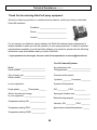
1
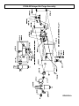
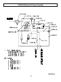
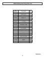
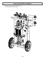
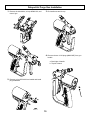
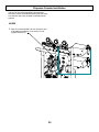
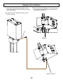
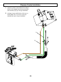
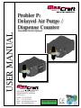
USER MANUAL
Probler P2
Delayed Air Purge /
Dispense Counter
Guardian Series Options
5845 WEST 82ND STREET
INDIANAPOLIS, INDIANA
46278 U.S.A.
Phone (317) 875-5592
Fax
(317) 875-5456
Email [email protected]
Web www.glascraft.com
PATENT PENDING
Table Of Contents
Introduction
About This Manual.................................................................................................................................................... 1
Parts & Illustrations
Standard & Optional Equipment ............................................................................................................................... 2
Compnent Features ................................................................................................................................................. 3
23996-00 Delayed Air Purge Assembly .................................................................................................................... 4
23997-00 Dispense Counter Assembly .................................................................................................................... 7
Safety
Urethane Safe Handling and Use of Foam Equipment ............................................................................................ 10
Installation
Optional Guardian Mount Installation ......................................................................................................................
Delayed Air Purge Gun Installation .........................................................................................................................
Delayed Air Purge Installation .................................................................................................................................
Dispense Counter Gun Installation .........................................................................................................................
Dispense Counter Installation .................................................................................................................................
14
15
17
19
20
Operation
Initial Start-up Procedures ........................................................................................................................................ 24
Notes .......................................................................................................................................... 25
Limited Warranty Policy ........................................................................................................... 27
Technical Assistance ................................................................................................................ 28
For Your Reference ....................................................................................INSIDE BACK COVER
Introduction
About This Manual
Before operating, maintaining or servicing any
GlasCraft system, read and understand all of
the technical and safety literature provided with
GlasCraft products. If you do not have the proper or related manuals and safety literature for
your GlasCraft system, contact your GlasCraft
distributor or GlasCraft, Inc.
This manual provides information for the assembly, operation, maintenance and service of this
GlasCraft product as used in a typical configuration. While it lists standard specifications and
procedures, some deviations may be found.
In this GlasCraft technical and safety publication, the following advisories will be provided
where appropriate:
NOTE
In order to provide our users with the most upto-date technology possible, we are constantly
seeking to improve products. If technological
change occurs after a product is on the market,
we will implement that technology in future production and, if practical, make it available to current users as a retrofit, up-date or supplement.
If you find some discrepancy between your unit
and the available documentation, contact your
GlasCraft distributor to resolve the difference.
GlasCraft, Inc. reserves the right to change or
modify this product as it deems necessary.
Is information about the procedure in progress.
CAUTION
Is imperative information about equipment
protection.
WARNING
Careful study and continued use of this manual
will provide a better understanding of the equipment and process, resulting in more efficient
operation, longer trouble-free service and faster,
easier troubleshooting.
Is imperative information about personal safety.
The information in this document is intended
only to indicate the components and their normal
working relationship typical use. Each assembly
should be directed by a GlasCraft distributor or
made from the GlasCraft assembly instructions
provided.
Parts & Illustrations
Model - Delayed Air Purge
Standard Equipment
23996-00
DELAYED AIR PURGE ASSEMBLY
GC-1409
USER MANUAL
Model - Dispense Counter
Standard Equipment
23997-00
DISPENSE COUNTER
GC-1409
USER MANUAL
Mounting Options
Optional Equipment
23949-00
GUARDIAN SERIES MOUNTING BRACKET KIT
Component Features
DELAYED AIR PURGE FEATURES
The control box receives a signal from the gun, once the signal is received the air purge is shut off via the Air Purge
control Valve (APCV), this valve is held in with the Delay Spool Valve (DSV). When the trigger is released the gun signnal is cancelled to the DSV, the DSV then begins to count down to reset mode, once complete the APCV is reset and
air purge resumes.
The DSV is adjustable up to 15 seconds of delay. Factory set point is 2 seconds. To adjust the time delay of the DSV,
remove the plug #7279-09 from cover. Use a small flat head screw driver, turn clock wise to increase delay time, counter clock wise to decrease delay.
The operator is responsible for recognizing the air purge delay time verses gel time of the materials being processed
with this equipment to ensure the gun does not prematurely set up. The Red eye on the front panel indicates when the
APCV is open, allowing air purge to the gun. The on/off switch will by-pass the signal air to the DSV, allowing the gun
to be operated normally with out the delay action of air purge.
DISPENSE COUNTER FEATURES
The control box receives a signal when the gun trigger is activated, to activate the timer, the timer counter receives signal from the change over switches. Pneumatic drive systems use a 3 way check valve and receive signal from both upper and lower switches, making the timer a “stroke counter”. Hydraulic drive systems use a single signal, typically to
the lower signal switch, making the timer a “cycle counter”.
When the predetermined count is reached the timer activates the bimba cylinder in the back of the gun to overcome
the trigger at the gun, the operator will need to recognize this “feel” of the trigger and release the trigger.
When the gun trigger is released the signal air is cancelled to a delay spool valve (DSV) located in box assembly.
The DSV delays the reset of the counter for 3 seconds.
The timer will reset to the set point and cancel the air to the actuation cylinder.
The on/off switch will by-pass the counter signal allowing the system to operated independent of the counter.
COUNTER CALCULATIONS
Stroke output = .021 gallon
Cycle output = .042 gallons
23996-00 Delayed Air Purge Assembly
REVISION A
23996-00 Delayed Air Purge Assembly
REVISON A
23996-00 Delayed Air Purge Parts List
Part
Number
Description
Qty.
11021-22
PIPE PLUG
1
1880-00
HOSE FITTING
2
19881-00
PLUG FITTING
2
20735-01
ELBOW FITTING
2
20750-00
SWIVEL TEE
1
20796-02
FITTING
1
21660-00
CONTROL VALVE
1
22205-00
“L” FITTING
2
22211-00
SPOOL VALVE
1
22212-01
BULKHEAD FITTING
1
22212-02
BULKHEAD FITTING
2
22218-00
PUSH-ON HOSE FITTING
9
22230-00
REGULATOR FILTER
1
22237-00
HEX STANDOFF
2
22240-00
VALVE MOUNTING PLATE
1
22242-00
PRESSURE INDICATOR
1
22273-00
DELAY VALVE
1
22706-16
SCREW
4
23947-00
DELAYED AIR PURGE KIT
1
23993-00
DELAY/TIMER BOX
1
23995-00
DELAY BOX COVER
1
7279-10
SNAP-IN HOLE PLUG
1
7279-11
SNAP-IN HOLE PLUG
1
7730-12F
SCREW
2
8115-02
FITTING
2
ISD-142
SOLVENT POT GAUGE
1
REVISION A
23997-00 Dispense Counter Assembly
REVISION A
23997-00 Dispense Counter Assembly
REVISION A
23997-00 Dispense Counter Parts List
Part
Number
Description
Qty.
10080-03
BARB HOSE FITTING
1
11021-22
PIPE PLUG
1
1880-00
FITTING
1
19881-00
PLUG FITTING
2
20750-00
SWIVEL TEE
1
20796-00
FITTING
1
20796-02
FITTING
1
21660-00
CONTROL VALVE
1
22205-00
”L” FITTING
1
22212-01
BULKHEAD FITTING
2
22212-02
BULKHEAD FITTING
2
22218-00
PUSH-ON HOSE FITTING
13
22219-00
PREDETERMINING COUNTER
1
22230-00
REGULATOR FILTER
1
22237-00
HEX STANDOFF
2
22240-00
VALVE MOUNTING PLATE
1
22273-00
DELAY VALVE
1
22624-00
SPOOL VALVE
1
22706-16
SCREW
4
23948-00
DISPENSE COUNTER KIT
1
23993-00
DELAY/TIMER BOX
1
23994-00
TIMER BOX COVER
1
7730-12F
SCREW
2
8115-02
FITTING
2
ISD-142
SOLVENT POT GAUGE
1
REVISION A
SAFETY
Safe Handling And Use Of Urethane Foam
Equipment
Organic Peroxides and Dual Component Coatings. Local
codes and authorities also have standards to be followed
in the operation of your spraying equipment. Chemical
manufacturer’s recommendations should be obtained
and considered. Your insurance carrier will be helpful in
answering questions that arise in your development of
safe procedures.
Introduction
Any tool, if used improperly, can be dangerous. Safety
is ultimately the responsibility of those using the tool. In
like manner, safe operation of polyester processes is
the responsibility of those who use such processes and
those who operate the equipment. This manual outlines
procedures to be followed in conducting polyester operations safely.
Personnel Safety Equipment
GlasCraft recommends the following Personal Safety
Equipment for conducting safe operations of the Polyester Systems:
All personnel involved in dispensing operations should
read and understand this manual. It is most important
that equipment operators, maintenance, and supervisory personnel understand the requirements for safe
operation.
This manual cannot answer every circumstance; each
user should examine his own operation, develop his
own safety program and be assured that his equipment
operators follow correct procedures. GlasCraft hopes
that this manual is helpful to the user and recommends
that the precautions in this manual be included in any
such program.
GlasCraft recommends that the user consult the state
and local regulations established for all Safety equipment
listed.
Urethane foam systems are comprised of several different chemical compounds, some of which may be hazardous if improperly used.
1.
Handle chemicals safely.
2.
Provide adequate ventilation.
3.
Provide adequate safety equipment (gloves, respirators, safety glasses, protective clothing, etc.) for operators and all others working in areas where they may
be exposed to the chemicals or their vapors.
4.
Avoid operating equipment which has given any
indication of malfunction.
5.
Become fully acquainted with the equipment and
chemicals used.
Operating Safely
In operating urethane foam equipment safely, user should
make every effort to:
CAUTION
Particular caution must be taken with respect to the
vapors released during the use of urethane foam systems.
Isocyanate compounds are used in urethane foaming
operations. The medical history of persons who may be
exposed to such isocyanates should be examined. It is
recommended that individuals with a history of chronic
respiratory ailments should avoid exposure to all isocyanates.
Handling Chemicals Safely
Storage of polyisocyanates, diamines, and organic solvents should be isolated and restricted to specially constructed storage rooms. Store chemicals in original containers and according to manufacturer’s recommendations
listed on the container. Maximum ambient temperatures
to which such chemicals should be exposed are specified
by the manufacturer and MUST NOT be exceeded either
in the storage area or in the spraying or pouring area.
In addition to the manual, GlasCraft recommends that
the user consult the regulations established under the
Occupational Safety & Health Act (OSHA), particularly
the following sections:
•
•
•
1910.94 Pertaining to ventilation.
1910.106 Pertaining to flammable liquids.
1910.107 Pertaining to spray finishing opera
tions, particularly Paragraph (m)
10
SAFETY
3.
Equipment capable of withstanding pressure. When HHC solvents contact aluminum or galvanized parts inside a closed container, such as a pump,
spray gun, or fluid handling system, the chemical reaction can, over time, result in a build-up of heat and pressure, which can reach explosive proportions.
To avoid moisture contamination, do not open containers until ready for use. After use, the remaining material
should be re-sealed in the original container and stored in
areas away from moisture.
During clean-up of spilled isocyanate component, respirators, gloves and eye protection must be worn. Isocyanates
which have been spilled can be controlled by covering
them with dry sawdust and/or other absorbent, inert materials. Care should be taken to avoid skin contact. The absorbent material and the absorbed isocyanate should be
collected promptly, placed in an open-top container, and
treated with dilute solutions of ammonium hydroxide and/
or alcohol. While being treated in this manner, the material
should be in an adequately ventilated area. Clothing on
which any material has been spilled should be removed
immediately, and cleaned before being worn again.
When all three elements are present, the result can be
an extremely violent explosion. The reaction can be
sustained with very little aluminum or galvanized metal:
any amount of aluminum is too much.
The reaction is unpredictable. Prior use of an HHC
solvent without incident (corrosion or explosion) does
NOT mean that such use is safe. These solvents can
be dangerous alone (as a clean-up or flushing agent) or
when used as a component of a coating material. There
is no known inhibitor that is effective under all circumstances. Furthermore, the mixing of HHC solvents with
other materials or solvents, such as MEK, alcohol, and
toluene, may render the inhibitors ineffective.
Clean-Up Solvents
WARNING
A hazardous situation may be present in your pressurized
fluid system!
The use of reclaimed solvents is particularly hazardous.
Reclaimers may not add any inhibitors, or may add
incorrect amounts of inhibitors, or may add improper
types of inhibitors. Also, the possible presence of water
in reclaimed solvents could feed the reaction.
Halogenated Hydrocarbon Solvents can cause an explosion when used with aluminum or galvanized components
in a closed (pressurized) fluid system (pumps, heaters, filters, valves, spray guns, tanks, etc.).
Anodized or other oxide coatings cannot be relied upon
to prevent the explosive reaction. Such coatings can be
worn, cracked, scratched, or too thin to prevent contact.
There is no known way to make oxide coatings or to
employ aluminum alloys, which will safely prevent the
chemical reaction under all circumstances.
The explosion could cause serious injury, death and/or
substantial property damage.
Cleaning agents, coatings, paints, etc. may contain Halogenated Hydrocarbon Solvents.
Several solvent suppliers have recently begun promoting HHC solvents for use in coating systems. The
increasing use of HHC solvents is increasing the risk.
Because of their exemption from many State Implementation Plans as Volatile Organic Compounds (VOC’s),
their low flammability hazard, and their not being classified as toxic or carcinogenic substances, HHC solvents
are very desirable in many respects.
Some GlasCraft spray equipment includes aluminum or
galvanized components and will be affected by
Halogenated Hydrocarbon Solvents.
There are three key elements to the Halogenated Hydrocarbon (HHC) solvent hazard.
1.
The presence of HHC solvents. 1,1,1-Trichloro
ethane and Methylene Chloride are the most common of
these solvents. However, other HHC solvents are suspect
if used; either as part of paint or adhesives formulation, or
for clean-up or flushing.
2.
Aluminum or Galvanized Parts. Most handling
equipment contains these elements. In contact with these
metals, HHC solvents could generate a corrosive reaction
of a catalytic nature.
11
SAFETY
WARNING
Adequate ventilation (as covered in OSHA Section
1910.94 and NFPA No. 91) is important wherever solvents are stored or used, to minimize, confine and exhaust the solvent vapors.
If you are now using Halogenated Hydrocarbon solvents
in pressurized fluid systems having aluminum or galvanized wetted parts,
IMMEDIATELY TAKE THE FOLLOWING STEPS:
•
Empty system, shut-off, completely depressurize in accordance with equipment service instructions.
•
Remove equipment from service, disassemble
in accordance with equipment servicing instructions.
•
Inspect all parts for corrosion and/or wear. Replace any damaged parts.
•
Thoroughly clean all parts of the equipment with
a non-halogenated solvent and reassemble in accordance with equipment servicing instructions.
•
Flush equipment with non-halogenated solvent.
•
Do NOT reuse equipment with HHC solvents or
with materials containing such solvents.
•
Material suppliers and/or container labels should
be consulted to ensure that the solvents used are compatible with your equipment.
Solvents should be handled in accordance with OSHA
Section 1910.106 and 1910.107.
Toxicity of Chemicals
GlasCraft recommends that you consult OSHA Sections
1910.94, 1910.106, 1910.107 and NFPA No. 33, Chapter
14, and NFPA No. 91.
Contact your chemical supplier(s) and determine the toxicity of the various chemicals used, as well as the best
methods to prevent injury, irritation and danger to personnel.
Also determine the best methods of first aid treatment for
each chemical used in your plan
NOTE
First Aid
If chemicals containing isocyanate are splashed on the
skin, they can produce ill effects. Steps to counteract
such effects should be started immediately.
TAKE IMMEDIATE ACTION...
Halogenated Hydrocarbon solvents are dangerous
when used with aluminum components in a closed fluid
system.
Apply Tincture of Green Soap, full strength, to the contaminated area. If Tincture of Green Soap is not immediately available, wash the exposed area repeatedly with
soap and water. Soap and water is not as desirable as
using Tincture of Green Soap because many isocyanate
components are not easily dissolved in water. In addition,
soap and water does not form a barrier to the isocyanate.
GlasCraft is aware of NO stabilizers available to prevent
Halogenated Hydrocarbon solvents from reaction under
all conditions with aluminum components in a closed
fluid system.
Consult your material supplier to determine whether your
solvent or coating contains Halogenated Hydrocarbon
Solvents.
After approximately two to four minutes, wash off the
Tincture of Green Soap with water. If there is still an indication of isocyanate present, repeat the application. If the
isocyanate contamination is on the facial area, care must
be taken to avoid getting the Tincture of Green Soap in
the eyes.
GlasCraft recommends that you contact your solvent
supplier regarding the best non-flammable clean-up solvent with the heat toxicity for your application.
If, however, you find it necessary to use flammable
solvents, they must be kept in approved, electrically
grounded containers.
If the person develops breathing difficulties, oxygen
should be administered. Quite often the exposed person
will experience residual effects such as coughing spells.
CONTACT PHYSICIAN IMMEDIATELY.
Bulk solvent should be stored in a well-ventilated, separate building, 50 feet away from your main plant.
WARNING
Contact a doctor immediately in the event of an injury
and give him the information you have collected. If your
information includes first aid instructions, administer first
aid immediately while you are contacting the doctor.
You should allow only enough solvent for one day’s use
in your laminating area.
“NO SMOKING” signs must be posted and observed in
all areas of storage or where solvents and other
flammable materials are used.
12
SAFETY
If a person accidentally swallows isocyanate, large
amounts of water should be swallowed immediately.
Vomiting should then be induced by patient sticking his
finger down his throat, or by swallowing large quantities
of warm salt water or warm soapy water. After vomiting,
more water should be taken to dilute isocyanate further.
CONTACT PHYSICIAN IMMEDIATELY.
In industrial and contractor applications, it is advisable
to run frequent tests to determine the exact concentration of isocyanate vapor in the air. Industrial equipment
is available for making such determinations. Your chemical supplier can recommend such equipment and procedures.
Proper Safety Equipment
All persons spraying or working is areas where forced
air ventilation is not adequate to remove isocyanate vapors from the air MUST use an approved (U.S. Bureau
of Mines) fresh air supplied respirator.
Ventilation
WARNING
Hazardous concentrations of some chemical vapors exist before they can be smelled. Chemical component
suppliers should be contacted to determine at what
concentrations the vapors of the chemicals they supply
become dangerous, and the procedures and equipment
needed to detect such dangerous concentrations. Such
equipment should be obtained.
Respirators should be regularly inspected, cleaned and
disinfected according to good practices. Records must
be kept of the inspections. The user MUST have a medical clearance indicating that he can safely use a respirator.
Adequate ventilation must be provided in any area where
foam chemicals are sprayed or poured, and wherever
the material containers are opened.
Respirators must fit securely; beards prevent a tight seal
around the face. Eye glasses have to be given special
attention and contact lenses are prohibited.
In industrial applications, foaming operations should be
restricted to specific areas, and proper ventilation should
be provided in these areas to prevent chemical vapors
from spreading. Spray foaming operations MUST be restricted to a spray booth where a minimum exhaust of
100 feet per minute at the face of the booth is provided.
Special care should be taken to prevent unsuspecting
personnel both inside and outside of the plant from being exposed to chemical vapors. The chemical vapors
should be exhausted to atmosphere in such a manner
and at a sufficiently low concentration that personnel
outside the plant are not exposed to dangerous concentrations of chemical vapors. Refer to OSHA Standards,
sub-part G, 1910.107 and particularly sub-section (m)
for Federal standards. State and local authorities may
have applicable statutes or regulations concerning ventilation.
Safety goggles, gloves and other protective devices are
suggested for operators of foaming equipment. Refer to
OSHA Standards, sub-part 1, 1910.132, 1910.133 and
1910.134 for Federal standards.
IF YOU HAVE ANY QUESTIONS REGARDING THE
ABOVE PRECAUTIONS OR ANY SERVICE OR OPERATION PROCEDURES, CALL YOUR GLASCRAFT
DISTRIBUTOR OR GLASCRAFT, INC.
NOTICE
All statements, information and data given herein are
believed to be accurate and reliable but are presented
without guaranty, warranty or responsibility of any kind
expressed or implied. The user should not assume that
all safety measures are indicated or that other measures
are not required.
In contractor applications (for example, at a construction
site, inside building or other enclosed space), the forced
ventilation normally provided is likely to be inadequate.
These applications, therefore, usually REQUIRE the use
of forced, fresh air respirators for all persons in the areas
where foaming operations are conducted or where the
chemical vapors are likely to spread.
5845 WEST 82nd STREET, SUITE 102
INDIANAPOLIS, INDIANA 46278 U.S.A.
PHONE (317) 875-5592
13
FAX (317) 875-5456
Optional Guardian Mount Installation
1. Install the mounting bracket #23949-00 by securing
the band clamps to the frame as shown.
14
Delayed Air Purge Gun Installation
1. Remove the side blocks, air cap #23961-00, and
nose of gun
3. Re-install nose and air cap
4. Remove the two 10-32 plugs (#9936-08F) from gun
handle
a. Back right of handle
b. Top left of barrel
2. Remove o-ring #7554-06 from handle and install
plug #23998-00
15
Delayed Air Purge Gun Installation
5. Install RS-143 & 10080-01 on the top of the gun
barrel, the #9704-03 air trigger tubing connects to
this fitting.
7. Reinstall side blocks after initial system start up is
complete.
6. Install 20796-02 on the back right port, the 20732-04
signal air tubing connects to this fitting.
16
Delayed Air Purge Installation
The box can be remote mounted to the operators
discretion, bracket kit #23949-00 allows both the Delay
box and timer box to be mounted to Guardian series
systems.
HOSES
1. Main air: Connect air hose #19507-03 from an
accessory port on the Guardian air manifold, or line
source to the air inlet regulator #22230-00
2. Air Purge: Connect air hose #19507-02 from lower
¼” nps fitting on box assembly to main hose assembly air line (going to gun)
17
Delayed Air Purge Installation
3. Air trigger: Connect tubing #9704-03 to the elbow on
back side of inlet regulator, run tubing with the main
hose assembly up to gun, see gun installation.
4. Air Signal: Connect tubing #20732-04 to the 5/32”
port on bottom of box, run tubing with the main hose
assembly up to gun, see gun installation.
Tubing 9704-03
To gun
Tubing 20732-04
To gun
18
Dispense Counter Gun Installation
1. Remove trigger plug #23967-00, spring #PG-19, and
10-32 plug #9936-08F from back of gun.
3. Install #19938-00 spring, # 19937-01 cylinder
adapter, # 19936-00 cylinder, #20796-00 fitting. The
#9704-03 actuator tubing connects to this fitting.
2. Install # 20796-02 in 10-32 port, the 20732-04 signal
air tubing connects to this fitting
19
Dispense Counter Installation
The box can be remote mounted to the operators
discretion, bracket kit #23949-00 allows both the Delay
box and timer box to be mounted to Guardian series
systems.
HOSES
1. Main air: Connect #19507-03 from accessory port
of Guardian air manifold, or line source to inlet
regulator #22230-00.
20
Pneumatic Unit Installation
1. Counter input: Connect #21203-00 from barb fitting
on the bottom of control the box to the drive cylinder
switches. See signal switch paragraph.
2. locate upper signal tubing (clear) and cut line 1 ½”
3. Locate lower signal tubing (blue) and cut line 1 ½”
from signal valve.
4. Install counter stroke signal tee sub-assembly, in line of
each signal valve line
from signal valve.
1
2
4
3
4
21
Hydraulic Unit Installation
1. locate lower signal tubing from change over box
(Note: this is the 5/32” bulkhead fitting to the inside
of the bottom plate)
3. Remove #22218-00 barb fitting from bottom of control
box and install #20796-03 fitting, connect #20732-03
clear tubing from switch tee
2. Cut 5/32” line and install #22224-00 tee, install
#20732-03 tubing.
2
REMOVE
INSTALL 20796-03
22
Dispense Counter Installation
1. Actuation cylinder: Connect #9704-53 to fitting in
bottom of box (center) route this hose with main
hose assembly up to gun. See gun installation.
2. Air Signal: Connect #20732-04 to 5/32” port on
bottom (left) of box, run hose w/ main hose
assembly up to gun, see gun installation.
1
2
23
Operation
START UP DELAYED AIR PURGE
START UP PNEUMATIC COUNTER
1. Prime system per system manual instructions.
1. Prime system per manual instructions
2. Set air regulator to 120 psi, this is recommended
2. Set air regulator to 100 psi, this is recommended
3. Push slide valve to the “ON” position on the gun, air
3. Depress and hold set button (to left of counter face)
operation pressure, 90 psi is minimum recommended
set point.
operation pressure, 90 psi is minimum recommended set point.
depress each corresponding push button to set cycle
count
purge should be on.
4. Trigger Gun and hold
a. The “Red eye” on the control box face should pull
“off”
a. I.E. 00015 = 15 pump cycles
4. It is recommended to test spray system before
activating the timer box. During initial start up leave
Timer box “on/off” switch to the “off” position.
5. Release gun trigger
a. Air purge should not be present & “red eye” “off”
for 2 seconds
5. After determining set point of counter, switch unit “on”
and begin operation
6. Air purge will resume and “red eye” be “on”
NOTE
The air purge requires at least 1 second of trigger “on” to
fully engage the delay spool & deactivate the air purge.
NOTE
The Timer requires at least 1 second of trigger “on” to fully
engage the delay spool & activate the unit.
24
Notes
25
Notes
26
Limited Warranty Policy
GLASCRAFT, INC. (“GlasCraft”) warrants to the original Purchaser of GlasCraft manufactured equipment
and parts, that all GlasCraft manufactured equipment and parts will conform to their published written specifications and
be free of defects in workmanship and material for a period of one (1) year from the original date of installation. GlasCraft
makes no warranty to anyone other than the original Purchaser.
If any GlasCraft manufactured part or equipment is found to be defective in workmanship or material within the one-year
period from the date of installation, as determined solely by GlasCraft, GlasCraft, in its sole discretion, will either repair
or replace the defective part or equipment at GlasCraft’s cost, including freight charges both ways, or credit or refund the
purchase price for the defective equipment or part.
A warranty claim will be honored only when:
1. GlasCraft has been informed, in writing, of any such defect in workmanship or material within ten (10) days
after discovery by the original Purchaser;
2. An official of GlasCraft has issued a return authorization number; and
3. The claimed defective equipment or part has been returned to GlasCraft by the original Purchaser, freight
prepaid (with proper return authorization number(s) attached), to: GlasCraft, Inc., 5845 West 82nd Street,
Suite 102, Indianapolis, IN 46278, U.S.A.
This warranty shall not apply to any equipment or parts that have been altered or repaired by anyone other than GlasCraft
or to defects or damage resulting from improper installation, misuse, negligence, accident, or use not specified by
GlasCraft. This warranty shall not apply to any equipment where any parts or components were replaced by any parts
or components not manufactured or supplied by GlasCraft. The decision by GlasCraft shall be conclusive and binding
on Purchaser.
GlasCraft does not warrant that any equipment or parts sold to Purchaser meet or comply with any local, state, federal,
or other jurisdiction’s regulations or codes. GlasCraft does not warrant that any equipment or part sold to Purchaser,
when used individually or in concert with any other part, equipment, device, component or process, does not infringe on
any patent rights of any third party. GlasCraft only warrants that it has no specific knowledge of any such infringement.
GlasCraft makes no warranty as to any parts or equipment manufactured by others. Purchaser shall look solely and
only to the manufacturer of such parts or equipment with respect to any warranty claims. GlasCraft hereby assigns to
Purchaser the original manufacturer’s warranties to all such equipment and parts, to the full extent permitted.
THE AFORESAID WARRANTY IS IN LIEU OF ALL OTHER WARRANTIES, EXPRESSED OR IMPLIED. SPECIFICALLY THERE ARE NO WARRANTIES OF MERCHANTABILITY OR FITNESS
FOR A PARTICULAR PURPOSE, WHICH WARRANTIES ARE SPECIFICALLY DISCLAIMED.
GlasCraft shall not be liable for any loss or expense resulting from damage or accidents caused by improper use or application of materials manufactured or sold by GlasCraft or its distributors or agents.
UNDER NO CIRCUMSTANCES SHALL GLASCRAFT’S LIABILITY EXCEED THE AMOUNT PURCHASER PAID FOR THE CLAIMED DEFECTIVE EQUIPMENT OR PART. UNDER NO CIRCUMSTANCES SHALL GLASCRAFT BE LIABLE FOR INCIDENTAL OR CONSEQUENTIAL DAMAGES OR FOR LOST PROFITS.
No action arising from or relating to any goods manufactured by or purchased from GlasCraft may be brought more than
one (1) year after the cause of action accrues.
27
Technical Assistance............
Thank You for selecting GlasCraft spray equipment
Should you have any questions or need technical assistance, contact your factory authorized
GlasCraft distributor.
Distributor: _________________________
Phone: ____________________________
Contact: ___________________________
For any issues your distributor cannot address, the GlasCraft technical service department is
always available to assist you with the operation of your spray equipment. To help our technical
representatives expedite your call and better address your questions, please have the following
information ready and available when you phone GlasCraft.
* If your questions are not urgent, You can e-mail all correspondence to [email protected]
For Air Powered Systems:
Model: _____________________________
Serial number: _______________________
Air compressor size: __________________
CFM generated: _____________________
Type of spray gun: ____________________
Serial number: _______________________
Pressure at the system:
Is your equipment:
Dynamic fluid pressure:
Single phase: _______ Three phase ______
ISO __________ POLY ___________
What is the inbound voltage
to your equipment: ____________________
Spray gun chamber size: ______________
Hydraulic ________ Pneumatic _________
Material being sprayed: _______________
Temperature setting ISO: _______________
Viscosity: ISO _________ POLY ________
Temperature setting POLY: ______________
Approximate material temperature: ______
Temperature setting HOSE: _____________
28
For Your Reference
Date Purchased
__________________________________________________
Distributor
______________________________________________________
______________________________________________________
Contact
______________________________________________________
Phone
______________________________________________________
E-mail
______________________________________________________
GlasCraft manufactures a complete line of polyurethane foam and polyurea coating spray systems.
If your application is in-plant or a field contractor - GlasCraft has a system package to meet your
requirements.
GUARDIAN - AIR POWERED / A5 & A6 SERIES EQUIPMENT
. 6000 OR 12000 WATTS OF HEAT
. 1600, 2200, OR 3000 PRESSURE SET-UPS AVAILABLE
MH, MH II, & MH III HYDRAULIC POWERED SYSTEMS
. UP TO 45 LBS / MINUTE OUTPUT
. EXCELLENT PERFORMANCE AND RELIABILITY
GUARDIAN MMH - MOBILE MODULAR HYDRAULIC SYSTEMS
. SPECIFICALLY DESIGNED FOR ANY TYPE OF SPRAY RIG
. GIVE COMPLETE UTILIZATION OF FLOOR SPACE IN MOBILE RIG
PROBLER P2 SPRAY GUN
. IMPINGEMENT MIX / AIR PURGE
. OPTIONAL NOZZLE FOR SPRAYING STUD WALLS, POURING & STREAM JET
For more information concerning any of these GlasCraft products,
contact your local authorized GlasCraft distributor or visit www.glascraft.com
Quality and Performance…
GENUINE GLASCRAFT
www.glascraft.com
GC-1409
REVISION A.2
5845 WEST 82nd STREET
INDIANAPOLIS, INDIANA 46278
U.S.A.
Phone (317) 875-5592
Fax (317) 875-5456
[email protected]