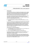
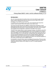
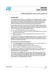
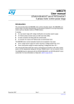
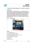
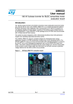
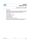
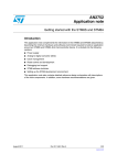
1
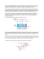
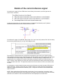
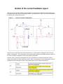
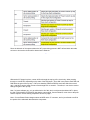
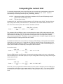
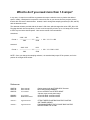
Overview
Current limitation operates based on the circuit shown on page 44 of UM0708.
The circuit operates by comparing the voltage of the ‘Current feedback’ signal, with the voltage present
on the ‘iRef’ signal (at the bottom of the comparator). When the current feedback exceeds the value of
iRef, the output (TIM1_ETR) is set to the high position. Otherwise, it is in the low position.
The TIM1_ETR signal has the effect of forcing all PWM signals associated with TIM1 to the inactive, for
the remainder of the PWM period. Therefore, once the current feedback reaches the limit, the pulse
width will be limited to ensure that sensed current does not exceed the value of iRef (independent of the
programmed duty cycle). Once the PWM signals are deactivated, the feedback signal will decay,
allowing the ETR pin to clear before the start of the next PWM period.
This concept is illustrated in the documentation from the ST7:
Note: The programmed duty cycle is represented by the leftmost pulse
(before current reached the limit)
When operating in voltage mode, the control software generates a fixed with PWM signal onto iRef
which corresponds with the desired current limit. Assuming a 5v supply, a PWM duty cycle of 50% will
generate a current reference of 2.5v. Similarly, a 25% duty cycle generates a limit of 1.25v.
Once the appropriate current limit has been set, the controller generates a variable width PWM signal,
where the width of the signal is proportional to the amount of power to be delivered to the motor. Due to
the load on the system, and the gains in the compensator, it is possible that the controller will generate a
PWM signal that would cause the motor to draw current in excess of the programmed current limit.
In this scenario, the comparator (shown above) ensures that this doesn’t happen. As the PWM to the
motor increases, so does the ‘current feedback’ running into the top of the comparator. When the
feedback voltage exceeds the programmed limit, the ETR pin is activated, and the PWM signals are
immediately deactivated.
This concept was also illustrated in the documentation for the ST7:
When operating in current mode, the software sets the PWM duty cycle to maximum permissible value,
and varies the iRef signal, based on the amount of current that is to be delivered. The comparator circuit,
shown above, will then limit the effective PWM duty cycle to provide the motor with the proper amount of
current.
This implies ‘current limit’ settings in the software do not directly apply [after ramp-up] when operating in
current drive mode. The value on the display, modified using the joystick, directly affects value of the iRef
signal. So this signal serves as the ‘commanded current’, rather than a current limitation.
For reference, here is the portion of the schematic that implements this comparator.
Details of the current reference signal
As mentioned on page 44 of the STM8 motor control library documentation, the iRef signal can be
sourced from 3 locations:
Looking at the schematic you can see that jumpers J13 (labeled Fixed/Variable) and J5 (labeled
sensorless/sensored) are used to to select the source of iRef.
As mentioned on page 16 of UMO709, when jumper J13 is set to the ‘fixed’ position, iRef is driven directly
from the blue potentiometer (P1) on top of the daughter board.
The discussion contained within the overview assumed that this jumper was in the ‘variable’ position,
where software has direct control of the iRef signal. With this jumper in the ‘fixed’ position, the iRef signal
is tied directly to the output voltage of the potentiometer. So when operating in voltage mode, the
potentiometer can be adjusted to increase or decrease the maximum amount of current the motor can
draw. However, when operating in current drive mode, the potentiometer directly controls the amount of
current provided to the motor. So adjustments made to the current reference via the user interface have
no effect.
It is noteworthy to mention that this jumper serves as a terrific place to monitor the value of iRef using a
digital multi-meter. With the jumper set to the ‘variable’ position, the multi-meter filters the signal and
displays a voltage proportional to the PWM duty cycle. A scope can be used to view the actual PWM
signal, if desired.
NOTE: When monitoring the iRef signal with a multi-meter, if you are operating in ‘sensorless’ mode,
make sure the hall effect sensors are not physically connected to the board (or the jumpers are removed).
Otherwise, the resistance of the sensors will affect the value displayed on the multi-meter.
Jumper J5, labeled sensorless/sensored, is used to select between TIM2_CH2 (sensorless) and
TIM1_CH4 (sensored).
Looking at the schematics, you find that TIM2_CH2 is tied to the signal MC-EncA, which is used in the
‘sensored’ configuration as one of the hall effect/encoder inputs. Therefore, it can only be used to drive
the iRef signal in a ‘sensorless’ configuration. In a ‘sensored’ configuration, you must use TIM1_CH4,
which is labeled as ‘Audio-PWM’ on the processor board schematic.
In either case, these signals change names when they transition from the processor board to the
daughter board (at connectors J6 and J7). TIM1_CHAN4 becomes the CR_Sensored signal, and
TIM2_CH2 becomes CR_Sensorless.
The setting of this jumper has fairly significant implications on the software. First of all, the preprocessor
directives HALL and SENSORLESS (MC_BLDC_Conf.h) must be set to match the position of the jumper.
These definitions specify which PWM channel should be used for the current limitation, as well as
management of the GPIO pins [sometimes] associated with the Hall Effect inputs.
Different timers are used to drive the PWM signal that source iRef, and the designers of the software
chose to use a different PWM frequencies for each timer. Timer 1 is also used to clock the PWM signals
associated with the motor windings, so when the iRef signal is sourced from TIM1_CH4, the PWM
frequency is 18 kHz (by default, or a value of 1333 when the STM8 is clocked at 24 mHz).
When timer 2 is used to source the iRef signal, a PWM frequency of approximately 6750 Hz is used (a
value of 500 with at 24 mHz clock). This value seems fairly arbitrary, as it is only used to program the
PWM period, and to convert a pulse width into the corresponding motor current value (see below).
The other significant difference, from a software perspective, is that when timer 1 is used, it is placed into
PWM mode #2, which implies that the output signal will remain low until the counter reaches the value of
the match register, and then it will be forced high. Timer 2 is configured for PWM mode #1, which keeps
the signal high until the counter reaches the value of the compare register.
This implies that when using timer #1 (i.e. sensored configuration), the value of the match register must
computed by taking the desired ‘on time’ for the output, and subtracting it from the PWM period (in clock
ticks). This step is not necessary when using timer #2 (i.e. sensorless configuration), and can be
problematic when the current limit specified exceeds the amount of current that can be sampled by the
sampling resistors R3, R4, and R5 (see Computing the current limit, below).
Details of the current feedback signal
The input of the comparator labeled ‘current feedback’ is sourced from the phase-B motor winding, after
being passed through a series of sampling resistors, and scaled by the op-amp. Here is a block diagram
from the power control board manual.
As you can see, jumper W7 is used to select between a ‘1 shunt resistor’ configuration and a ‘3 shunt
resistor’ configuration. The documentation also indicates that jumpers W8 and W9 should be in place for
the 3 shunt resistor configuration, which is the default configuration.
However, when I received my development kit, all ‘to be soldered’ connections were set for 1 shunt
resistor and neither W7, W8 nor W9 were present. Here is a description of each related jumper, with the
highlighted entries indicating the state of the jumpers when I received the development kit.
Since the behavior of the system without the W7 jumper being present is NOT defined within this table,
we have to look at the circuit itself to determine the behavior.
Without the W7 jumper in place, current will flow through the top leg of the circuit only, either passing
through or around R59, depending on the state of the W8 jumper. Since W8 is not present, both R59 and
R49 affect the gain of the op-amp. If W7 were installed, R48 and R55-58 would also affect the overall
gain. And W9 is used to allow current to flow through R61 or around it. Therefore, it can also be used to
change the gain of the op-amp.
Now, I’m just a software guy, so I get a little lost in all of this, but it would seem that without W7 in place,
the gain of the amplifier is sufficiently low that the output signal, Current Phase B, never rises to the point
where it trips the ‘current limiting comparator’ shown on page 1.
Note: Current Phase B also changes names to MCIB at the J7 connector, and is just referred to as IB in
the portion of the schematic that shows the comparator.
Computing the current limit
To determine the appropriate value for the iRef signal, one must take into consideration the gain of the
op-amp (shown above) as well as the value of the sampling resistors R3, R4, and R5. These are
represented by the following constants (in MC_PowerStage_Param.h).
• RS_M
• AOP
Indicates the number of milli-ohms of resistance in R3, R4, and R5 (although only R4
plays into the current limiting circuit)
The gain of the op-amp
As shipped, R3, R4, and R5 are 0.220 ohm resistors, so RS_M has a value of 220. The gain of the opamp (in single shunt mode) is documented as 12, and therefore, the constant AOP has a value of 12.
The macro that is used to perform the conversion is defined as follows:
Counts =
mAmps * RS_M
PMW_Freq_In_Counts
---------------------- * AOP * -------------------------------------1000
5000
The constants 1000 and 5000 are used to convert milliamps into amps (1000), and show that full scale
PWM represents 5.0 volts. When the input value of mAmps is in range, the computation will produce a
value between 0 and PWM_Freq_In_Counts that can be applied to the count register of the PWM
channel used to generate iRef. The problem comes in when the value of mAmps is higher than what can
be sampled using the sampling resistors that are installed.
As installed, the software has a current limit of 1.8 amps (1800 milliamps). Although the documentation
claims that you can sense up to 2.3 amps with the 0.220 ohm sampling resistor, the calculations in the
code break down before that limit is reached. To demonstrate, we’ll use a value of 2000 milliamps (2.0
Amps), and see what the corresponding count register values should be.
In sensorless mode:
Counts =
2000 * 220
500
---------------------- * 12 * --------- = 440 * 12 * 0.1 = 528
1000
5000
Since the PWM period is only 500 counts, this causes the compare register to be set to a value greater
than the PWM period, so the PWM output pin is kept in the high state continuously, setting the iRef signal
to the maximum value.
In sensored mode:
Counts =
2000 * 220
1333
---------------------- * 12 * --------- = 440 * 12 * 0.266 = 1407
1000
5000
Since TIM1_CH4 is programmed in PWM mode #2, this value must be subtracted from the PWM period
to compute the value written to the compare register. Since 1333 minus 1407 = -74, a value of 0xFFB6
will be written to the compare register, which forces the TIM1_CH4 pin to remain in the low state at all
times.
What to do if you need more than 1.8 amps?
In my case, 1.8 amps is not sufficient to generate the torque needed to move my load at the desired
speed. Initially, I attempted to increase the current limit, but as you can see from the previous section
that this did not have the desired effect. Instead, I had to change the sampling resistors (R3, R4, and R5)
with the alternative ones.
The alternate resistors provided with the kit were 0.100 ohms, which changes the value of RS_M to 100.
Plugging that back into the equations, I found I could now specify a limit of up to 4.16 amps, and I’m able
to move my load at the desired speed. Here are the results of the calculations:
sensorless:
Counts =
4160 * 100
500
---------------------- * 12 * --------- = 416 * 12 * 0.1 = 499
1000
5000
sensored:
Counts =
4160 * 220
1333
---------------------- * 12 * --------- = 416 * 12 * 0.266 = 1330
1000
5000
NOTE: Once you change the sampling resistors, it is essential that jumper W7 be present, and in the
position for a single shunt resistor.
References:
UM0708 UM0709 UM0379 -
User manual
User manual
User manual
UM0482 RM0016 -
User manual
Reference manual
AN1905 -
Application note
AN2009 -
Application note
- Getting started with the STM8S BLDC firmware
- BLDC daughterboard MB843
- STM3210B-MCKIT and STR750-MCKIT
3-phase motor control power stage
- STM8/128-EVAL evaluation board
- STM8/128-EVAL evaluation board
- ST7MC THREE-PHASE BLDC MOTOR CONTROL
SOFTWARE LIBRARY
- PWM MANAGEMENT FOR 3-PHASE BLDC MOTOR
DRIVES USING THE ST7MC