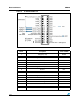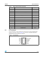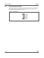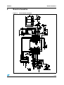
1
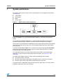
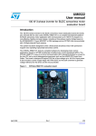
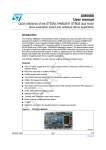
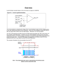
UM0430
User manual
IGBT Power module evaluation kit - ST7MC control board
Introduction
The ST7MC evaluation board STEVAL-IHM010V1 is a complete development platform for
STMicroelectronics' ST7MC microcontroller. Based on a cost effective, flexible and open
design, it allows easy demonstration of ST7MC capabilities and enables rapid evaluation of
the MTC microcontroller's peripherals. It includes the ST7MC 8-bit microcontroller with 16 K
internal Flash memory. The STEVAL-IHM010V1 features motor control Connector (MCConnector) and hardware features for developing motor control applications based on
ST7MC peripherals including motor control peripheral (MTC), Serial Communication
Interface (SCI). The STEVAL-IHM010V1 uses an In-Circuit Communication (ICC) standard
interface to connect to your host PC via In-Circuit Debuggers/Programmers like inDARTSTX board from Softec.
Figure 1.
STEVAL-IHM010V1
Features
July 2007
■
5 V power supply connector
■
34-pin dedicated motor control connector
■
Serial communication Interface connector
■
Programming and debug support via 10-pin ICC connector
■
Onboard 2K-bit (256 byte) serial memory
■
Four potentiometers for runtime settings
■
Start / stop button
■
Reset button
■
Debug pins available
Rev 2
1/48
www.st.com
Contents
UM0430
Contents
1
System architecture . . . . . . . . . . . . . . . . . . . . . . . . . . . . . . . . . . . . . . . . . 7
2
Safety and operating instructions . . . . . . . . . . . . . . . . . . . . . . . . . . . . . . 8
3
2.1
General . . . . . . . . . . . . . . . . . . . . . . . . . . . . . . . . . . . . . . . . . . . . . . . . . . . . 8
2.2
Reference design board intended use . . . . . . . . . . . . . . . . . . . . . . . . . . . . 8
2.3
Reference design board installation . . . . . . . . . . . . . . . . . . . . . . . . . . . . . . 8
2.4
Electronic connection . . . . . . . . . . . . . . . . . . . . . . . . . . . . . . . . . . . . . . . . . 8
2.5
Reference design board operation . . . . . . . . . . . . . . . . . . . . . . . . . . . . . . . 8
ST7FMC2S4T6 Microcontroller functions . . . . . . . . . . . . . . . . . . . . . . . . 9
3.1
Main features . . . . . . . . . . . . . . . . . . . . . . . . . . . . . . . . . . . . . . . . . . . . . . . 9
4
Control board electrical characteristics . . . . . . . . . . . . . . . . . . . . . . . . 11
5
Board architecture . . . . . . . . . . . . . . . . . . . . . . . . . . . . . . . . . . . . . . . . . . 12
5.1
MC Connector . . . . . . . . . . . . . . . . . . . . . . . . . . . . . . . . . . . . . . . . . . . . . 13
5.2
ICC connector . . . . . . . . . . . . . . . . . . . . . . . . . . . . . . . . . . . . . . . . . . . . . 15
5.3
Serial Data Interface (SDI) . . . . . . . . . . . . . . . . . . . . . . . . . . . . . . . . . . . . 16
6
Board schematics . . . . . . . . . . . . . . . . . . . . . . . . . . . . . . . . . . . . . . . . . . 17
7
Motor control demonstration . . . . . . . . . . . . . . . . . . . . . . . . . . . . . . . . . 18
7.1
Environmental considerations . . . . . . . . . . . . . . . . . . . . . . . . . . . . . . . . . 18
7.2
Hardware requirements . . . . . . . . . . . . . . . . . . . . . . . . . . . . . . . . . . . . . . 19
7.3
Software requirements . . . . . . . . . . . . . . . . . . . . . . . . . . . . . . . . . . . . . . . 19
7.3.1
7.4
2/48
Installing the software . . . . . . . . . . . . . . . . . . . . . . . . . . . . . . . . . . . . . . 19
Control board setup . . . . . . . . . . . . . . . . . . . . . . . . . . . . . . . . . . . . . . . . . 20
7.4.1
Choosing the right firmware . . . . . . . . . . . . . . . . . . . . . . . . . . . . . . . . . . 20
7.4.2
Configuring the firmware using GUI . . . . . . . . . . . . . . . . . . . . . . . . . . . . 21
7.4.3
Motor type selection . . . . . . . . . . . . . . . . . . . . . . . . . . . . . . . . . . . . . . . . 22
7.4.4
"3 Phase BLAC/DC (trapezoidal)" settings . . . . . . . . . . . . . . . . . . . . . . 23
7.4.5
"3 Phase BLAC/DC (trapezoidal)" advanced settings . . . . . . . . . . . . . . 25
7.4.6
“3 Phase AC induction motor (sinewave)” settings . . . . . . . . . . . . . . . . 27
7.4.7
"3 Phase AC induction motor (sinewave)" advanced settings . . . . . . . . 28
UM0430
Contents
7.5
7.6
7.7
7.8
7.4.8
"3 Phase PMAC motor (sinewave)" settings . . . . . . . . . . . . . . . . . . . . . 29
7.4.9
"3 Phase PMAC Motor (sinewave)" advanced settings . . . . . . . . . . . . . 31
7.4.10
Changing the maximum current allowed by GUI . . . . . . . . . . . . . . . . . . 32
7.4.11
Compiling the firmware . . . . . . . . . . . . . . . . . . . . . . . . . . . . . . . . . . . . . 32
7.4.12
Programming the firmware . . . . . . . . . . . . . . . . . . . . . . . . . . . . . . . . . . 33
7.4.13
Setup option byte . . . . . . . . . . . . . . . . . . . . . . . . . . . . . . . . . . . . . . . . . . 34
7.4.14
Jumper setting table . . . . . . . . . . . . . . . . . . . . . . . . . . . . . . . . . . . . . . . . 35
7.4.15
Board connection . . . . . . . . . . . . . . . . . . . . . . . . . . . . . . . . . . . . . . . . . . 35
Driving the AC induction motor . . . . . . . . . . . . . . . . . . . . . . . . . . . . . . . . . 36
7.5.1
Specific connection (sensor) . . . . . . . . . . . . . . . . . . . . . . . . . . . . . . . . . 36
7.5.2
Specific jumper settings . . . . . . . . . . . . . . . . . . . . . . . . . . . . . . . . . . . . . 37
7.5.3
LED behavior after power on . . . . . . . . . . . . . . . . . . . . . . . . . . . . . . . . . 37
7.5.4
Setting of potentiometer . . . . . . . . . . . . . . . . . . . . . . . . . . . . . . . . . . . . . 37
7.5.5
Run the motor (LED behavior) . . . . . . . . . . . . . . . . . . . . . . . . . . . . . . . . 37
7.5.6
Changing real-time parameters . . . . . . . . . . . . . . . . . . . . . . . . . . . . . . . 37
7.5.7
Stop the motor (LED behavior) . . . . . . . . . . . . . . . . . . . . . . . . . . . . . . . 38
Driving the BLDC Motor (trapezoidal - sensorless) . . . . . . . . . . . . . . . . . 38
7.6.1
Specific connection (sensor) . . . . . . . . . . . . . . . . . . . . . . . . . . . . . . . . . 38
7.6.2
Specific jumper settings . . . . . . . . . . . . . . . . . . . . . . . . . . . . . . . . . . . . . 38
7.6.3
LED behavior after power on . . . . . . . . . . . . . . . . . . . . . . . . . . . . . . . . . 39
7.6.4
Setting of potentiometer . . . . . . . . . . . . . . . . . . . . . . . . . . . . . . . . . . . . . 39
7.6.5
Running the motor (LED behavior) . . . . . . . . . . . . . . . . . . . . . . . . . . . . 39
7.6.6
Changing real-time parameters . . . . . . . . . . . . . . . . . . . . . . . . . . . . . . . 39
7.6.7
Stopping the motor (LED behavior) . . . . . . . . . . . . . . . . . . . . . . . . . . . . 40
Driving the BLDC Motor (trapezoidal - sensored) . . . . . . . . . . . . . . . . . . 40
7.7.1
Specific connection (sensor) . . . . . . . . . . . . . . . . . . . . . . . . . . . . . . . . . 41
7.7.2
Specific jumper settings . . . . . . . . . . . . . . . . . . . . . . . . . . . . . . . . . . . . . 41
7.7.3
LED behavior after power on . . . . . . . . . . . . . . . . . . . . . . . . . . . . . . . . . 41
7.7.4
Setting of potentiometer . . . . . . . . . . . . . . . . . . . . . . . . . . . . . . . . . . . . . 41
7.7.5
Running the motor (LED behavior) . . . . . . . . . . . . . . . . . . . . . . . . . . . . 41
7.7.6
Changing real-time parameters . . . . . . . . . . . . . . . . . . . . . . . . . . . . . . . 42
7.7.7
Stopping the motor (LED behavior) . . . . . . . . . . . . . . . . . . . . . . . . . . . . 43
Driving the BLAC motor . . . . . . . . . . . . . . . . . . . . . . . . . . . . . . . . . . . . . . 43
7.8.1
Specific connections (sensor) . . . . . . . . . . . . . . . . . . . . . . . . . . . . . . . . 43
7.8.2
Specific jumper settings . . . . . . . . . . . . . . . . . . . . . . . . . . . . . . . . . . . . . 43
7.8.3
LED behavior after power on . . . . . . . . . . . . . . . . . . . . . . . . . . . . . . . . . 44
7.8.4
Setting of potentiometer . . . . . . . . . . . . . . . . . . . . . . . . . . . . . . . . . . . . . 44
3/48
Contents
UM0430
7.8.5
Running the motor (LED behavior) . . . . . . . . . . . . . . . . . . . . . . . . . . . . 44
7.8.6
Changing real-time parameters . . . . . . . . . . . . . . . . . . . . . . . . . . . . . . . 44
7.8.7
Stopping the motor (LED behavior) . . . . . . . . . . . . . . . . . . . . . . . . . . . . 45
8
Bill of materials . . . . . . . . . . . . . . . . . . . . . . . . . . . . . . . . . . . . . . . . . . . . 46
9
References . . . . . . . . . . . . . . . . . . . . . . . . . . . . . . . . . . . . . . . . . . . . . . . . 47
10
Revision history . . . . . . . . . . . . . . . . . . . . . . . . . . . . . . . . . . . . . . . . . . . 47
4/48
UM0430
List of tables
List of tables
Table 1.
Table 2.
Table 3.
Table 4.
Table 5.
Table 6.
Table 7.
Table 8.
Table 9.
Table 10.
Table 11.
Table 12.
Table 13.
Table 14.
Table 15.
Table 16.
Table 17.
Table 18.
Table 19.
Table 20.
ST7FMC2S4T6 Functions . . . . . . . . . . . . . . . . . . . . . . . . . . . . . . . . . . . . . . . . . . . . . . . . . 10
Control board electrical characteristics . . . . . . . . . . . . . . . . . . . . . . . . . . . . . . . . . . . . . . . . 11
Motor control connector . . . . . . . . . . . . . . . . . . . . . . . . . . . . . . . . . . . . . . . . . . . . . . . . . . . 14
Firmware libraries arranged according to driving strategy . . . . . . . . . . . . . . . . . . . . . . . . . 21
Configuration ".h" files. . . . . . . . . . . . . . . . . . . . . . . . . . . . . . . . . . . . . . . . . . . . . . . . . . . . . 21
"3 Phase BLAC/DC (trapezoidal)" basic parameters . . . . . . . . . . . . . . . . . . . . . . . . . . . . . 23
"3 Phase BLAC/DC (trapezoidal)" advanced parameters. . . . . . . . . . . . . . . . . . . . . . . . . . 25
“3 Phase AC induction motor (sinewave)” basic parameters . . . . . . . . . . . . . . . . . . . . . . . 27
“3 Phase AC induction motor (sinewave)" advanced parameters . . . . . . . . . . . . . . . . . . . 28
"3 Phase PMAC motor (sinewave)" basic parameters . . . . . . . . . . . . . . . . . . . . . . . . . . . . 29
"3 Phase PMAC motor (sinewave)" advanced parameters . . . . . . . . . . . . . . . . . . . . . . . . 31
Jumper settings . . . . . . . . . . . . . . . . . . . . . . . . . . . . . . . . . . . . . . . . . . . . . . . . . . . . . . . . . 35
Potentiometer functionality based on open/closed loop driving strategy . . . . . . . . . . . . . . 38
Potentiometer functionality based on open/closed loop driving strategy . . . . . . . . . . . . . . 39
"BLDC Sensored" motor connections . . . . . . . . . . . . . . . . . . . . . . . . . . . . . . . . . . . . . . . . . 41
Potentiometer functionality based on open/closed loop driving strategy . . . . . . . . . . . . . . 42
"PMAC Sensored" motor connections . . . . . . . . . . . . . . . . . . . . . . . . . . . . . . . . . . . . . . . . 43
Potentiometer functionality based on open/closed loop driving strategy . . . . . . . . . . . . . . 44
Bill of materials . . . . . . . . . . . . . . . . . . . . . . . . . . . . . . . . . . . . . . . . . . . . . . . . . . . . . . . . . . 46
Revision history . . . . . . . . . . . . . . . . . . . . . . . . . . . . . . . . . . . . . . . . . . . . . . . . . . . . . . . . . 47
5/48
List of figures
UM0430
List of figures
Figure 1.
Figure 2.
Figure 3.
Figure 4.
Figure 5.
Figure 6.
Figure 7.
Figure 8.
Figure 9.
Figure 10.
Figure 11.
Figure 12.
Figure 13.
Figure 14.
Figure 15.
Figure 16.
Figure 17.
Figure 18.
Figure 19.
Figure 20.
Figure 21.
6/48
STEVAL-IHM010V1 . . . . . . . . . . . . . . . . . . . . . . . . . . . . . . . . . . . . . . . . . . . . . . . . . . . . . . . 1
Motor control system architecture. . . . . . . . . . . . . . . . . . . . . . . . . . . . . . . . . . . . . . . . . . . . . 7
Control board architecture . . . . . . . . . . . . . . . . . . . . . . . . . . . . . . . . . . . . . . . . . . . . . . . . . 12
Control board layout . . . . . . . . . . . . . . . . . . . . . . . . . . . . . . . . . . . . . . . . . . . . . . . . . . . . . . 13
MC Connector pin out . . . . . . . . . . . . . . . . . . . . . . . . . . . . . . . . . . . . . . . . . . . . . . . . . . . . . 14
ICC connector . . . . . . . . . . . . . . . . . . . . . . . . . . . . . . . . . . . . . . . . . . . . . . . . . . . . . . . . . . . 15
SDI connector . . . . . . . . . . . . . . . . . . . . . . . . . . . . . . . . . . . . . . . . . . . . . . . . . . . . . . . . . . . 16
Control board schematic . . . . . . . . . . . . . . . . . . . . . . . . . . . . . . . . . . . . . . . . . . . . . . . . . . . 17
STVD7 for InDART-STX Toolset configuration. . . . . . . . . . . . . . . . . . . . . . . . . . . . . . . . . . 20
Motor type choice window . . . . . . . . . . . . . . . . . . . . . . . . . . . . . . . . . . . . . . . . . . . . . . . . . 22
"3 Phase BLAC/DC (trapezoidal)" basic parameters window . . . . . . . . . . . . . . . . . . . . . . . 23
“3 Phase BLAC/DC (trapezoidal)" advanced parameters window . . . . . . . . . . . . . . . . . . . 25
3 Phase AC induction motor (sinewave)" basic parameters window . . . . . . . . . . . . . . . . . 26
"3 Phase AC induction motor (sinewave)" advanced parameters window . . . . . . . . . . . . . 28
"3 Phase PMAC motor (sinewave)" basic parameters window. . . . . . . . . . . . . . . . . . . . . . 29
"3 Phase PMAC motor (sinewave)" advanced parameters window . . . . . . . . . . . . . . . . . . 31
ST7VD active project configuration . . . . . . . . . . . . . . . . . . . . . . . . . . . . . . . . . . . . . . . . . . 32
System setup for programming phase . . . . . . . . . . . . . . . . . . . . . . . . . . . . . . . . . . . . . . . . 33
Option byte settings . . . . . . . . . . . . . . . . . . . . . . . . . . . . . . . . . . . . . . . . . . . . . . . . . . . . . . 34
Programming option auto window . . . . . . . . . . . . . . . . . . . . . . . . . . . . . . . . . . . . . . . . . . . 35
System setup for running phase . . . . . . . . . . . . . . . . . . . . . . . . . . . . . . . . . . . . . . . . . . . . . 36
UM0430
1
System architecture
System architecture
The generic motor control system can be schematized as the arrangement of four blocks
(see Figure 2):
●
Control block
●
Power block
●
Motor
●
Power supply
Figure 2.
Motor control system architecture
The system proposed for the IGBT power module eval kit is composed of one control board
STEVAL-IHM010V1, one power board STEVAL-IHM011V1, one motor and the power
supply.
The control board STEVAL-IHM010V1 is a microcontroller (ST7MC) based board that
provides the driving signals related to the motor selected and the driving strategies.
Driving signals are constituted of 6 PWM signals in the range of 0-5V paired in high side/low
side pairs of one pair for each leg. In the system proposed three legs are present (threephase inverter).
The power board STEVAL-IHM011V1 is based on the power module (STG3P2M10N60B)
that converts the control signal to power signals in order to drive the motor (see Power
Board User Manual for further details).
The connection between the control board and the power board is performed through
dedicated a 32-pin connector called “motor control connector” (see Section 5.1: MC
Connector).
The IGBT power module eval kit it is able to drive the following kinds of motors:
●
AC induction motor, sensored
●
Brushless permanent magnet motor (trapezoidal driven), sensored or sensorless
●
Brushless permanent magnet motor (sinusoidal driven), sensored
The power board is supplied by a high voltage AC power supply 220 V (or 110 V) with the
capability to generate current up to 10 amps.
7/48
Safety and operating instructions
2
Safety and operating instructions
2.1
General
UM0430
During assembly and operation, the IGBT power module eval kit poses several inherent
hazards, including bare wires, moving or rotating parts, and hot surfaces. There is danger of
serious personal injury and damage to property, if it is improperly used or installed
incorrectly.
All operations involving transportation, installation and use, as well as maintenance are to
be carried out by skilled technical personnel (national accident prevention rules must be
observed). For the purposes of these basic safety instructions, "skilled technical personnel"
are suitably qualified people who are familiar with the installation, use, and maintenance of
power electronic systems.
2.2
Reference design board intended use
The IGBT power module eval kit boards are components designed for demonstration
purposes only, and shall not be used for electrical installation or machinery. The technical
data as well as information concerning the power supply conditions shall be taken from the
documentation and strictly observed.
2.3
Reference design board installation
The installation and cooling of the reference design boards shall be in accordance with the
specifications and the targeted application (see Section 7: Motor control demonstration).
2.4
●
The motor drive converters shall be protected against excessive strain. In particular, no
components are to be bent, or isolating distances altered during the course of
transportation or handling.
●
No contact shall be made with other electronic components and contacts.
●
The boards contain electrostatically sensitive components that are prone to damage
through improper use. Electrical components must not be mechanically damaged or
destroyed (to avoid potential health risks).
Electronic connection
Applicable national accident prevention rules must be followed when working on the main
power supply with a motor drive. The electrical installation shall be completed in accordance
with the appropriate requirements (e.g., cross-sectional areas of conductors, fusing, PE
connections. For further information see Section 7: Motor control demonstration.
2.5
Reference design board operation
A system architecture which supplies power to the IGBT power module eval kit boards shall
be equipped with additional control and protective devices in accordance with the applicable
safety requirements (e.g., compliance with technical equipment and accident prevention
rules).
8/48
UM0430
ST7FMC2S4T6 Microcontroller functions
Warning:
Do not touch the design boards after disconnection from the
voltage supply, as several parts and power terminals which
contain possibly energized capacitors need to be allowed to
discharge.
3
ST7FMC2S4T6 Microcontroller functions
3.1
Main features
●
TQFP44 package
●
16 K dual voltage FLASH program memory with read-out protection capability
●
768 bytes RAM (256 Stack bytes)
●
Clock, Reset And Supply Management with:
–
enhanced reset system
–
enhanced low voltage supervisor (LVD) for main supply and auxiliary voltage
detector (AVD) with interrupt capability
–
clock sources: crystal/ceramic resonator oscillators and by-pass for external clock,
clock security system
–
four power saving modes: halt, active-halt, wait and slow
●
configurable window watchdog timer
●
nested interrupt controller with 14 interrupt vectors
●
two 16-bit timers,
●
one 8-bit auto-reload timer
●
Serial Peripheral Interface (SPI)
●
Serial Communication Interface (LINSCI™)
●
Motor Controller (MTC) peripheral with:
–
6 high sink Pulse Width Modulator (PWM) output channels
–
asynchronous Emergency Stop
–
analog inputs for rotor position detection
–
permanent magnet motor coprocessor including: multiplier, programmable filters,
blanking windows and event counters
–
Op Amp and Comparator for current limitation
●
10-bit Analog-to-Digital Converter (ADC) with 11 inputs
●
In-Circuit Communication Interface (ICC, debug)
9/48
ST7FMC2S4T6 Microcontroller functions
Table 1.
UM0430
ST7FMC2S4T6 Functions
Function
MTC
SPI
I/O name
Description (depends on embedded software)
MCO0 to MCO5
PWM outputs
MCIA, MCIB, MCIC
Analog or digital input for position sensor or B.E.M.F. detection
MCVREF
B.E.M.F. Detection comparator reference
NMCES
Emergency stop
OAP
Operational amplifier positive input
OAN
Operational amplifier negative input
OAZ
Operational amplifier output
MCCREF
Current limitation reference
MCPWMU
PWM Output U
MCPWMV
PWM Output V
MCPWMW
PWM Output W
MCZEM
Debug pin C/Z event
MCDEM
Debug pin C/D event
MISO
Master In/slave out data
MOSI
Master Out/slave In data
SCK
Serial clock
RDI
Received data input
TDO
Transmit data output
AIN0
Temperature sensor input
AIN1
Bus voltage sensing input
AIN13
Trimmer P1 reading input
AIN11
Trimmer P2 reading input
AIN4
Trimmer P3 reading input
ICCCLK
Output serial clock
ICCDATA
Input/Output serial data
ICCSEL/Vpp
Programming voltage input
PC2
RBC Resistive Brake Control
PC3
CTS Clear to send
PE0
Start/Stop pushbutton
PB0
LED management
OCMP1_B
PFC_PWM (1)
ICAPx_B
PFC_SYNC (1)
LINSCI™
10-bit ADC
ICC
Other I/O
16-bit Timer B
1. This function will be active only if it is available also in the power board.
10/48
UM0430
4
Control board electrical characteristics
Control board electrical characteristics
Stresses above the limit shown in Table 2 may cause permanent damage to the device. This
is a stress rating only and functional operation of the device under these conditions is not
implied. Exposure to maximum rating conditions for extended periods may affect device
reliability.
5 V Bias current measurement can be useful to check the working status of the board. If the
measured value is considerably greater than the typical value, it means that some damage
has occurred in the board.
Table 2.
Control board electrical characteristics
STEVAL-IHM010V1
Control board parameters
Unit
Min
Max
5 V Auxiliary supply range – J6
4.5
5.5
V
MC Connector pin 25 – 5V
4.5
5.5
V
MC Connector pin 28 – VDD Micro
4.5
5.5
V
5V Bias current (typical)
10
30
mA
MC PWM Output current (source)
25
mA
MC PWM Output current (sink)
50
mA
MC BEMF Input (sink)
25
mA
GP I/O Pin (source)
25
mA
GP I/O Pin (sink)
25
mA
HS I/O Pin (source)
25
mA
11/48
Board architecture
5
UM0430
Board architecture
The STEVAL-IHM010V1 can be schematized as in Figure 3.
Figure 3.
Control board architecture
The heart of the control board is the ST7MC microcontroller which is provided with a
dedicated peripheral to drive the three-phase brushless motor.
The user interface is constituted of four potentiometers (P1, P2, P3, P4) which are used to
set parameters related to the specific drive, see Section 7: Motor control demonstration.
Two push buttons are also present:
●
Reset button for a "hardware reset" of the board.
●
Start/stop button used to start and stop motor driving, see Section 7: Motor control
demonstration.
Two LEDs (green and red) provide information about the status of the system. Their
behavior is related to the specific drive, see Section 7: Motor control demonstration.
In normal functionality it is expected that the board is supplied by the MC connector, but for
stand-alone operation, an auxiliary supply connector for 5 V power supply is included on the
board. Providing more than 5.5 V through this connector may cause permanent damage to
the device since no over voltage protection device is present.
The board is supplied with 2 Kbit EEPROM (M95020) connected to the micro by an SPI bus.
To enable the onboard EEPROM memory, the jumper J2 must be closed and the debug
feature must be disabled inside the firmware.
J5 can be set by the user by connecting a jumper between pins 1-2 or 2-3. This setting is
related to a specific drive, see Section 7: Motor control demonstration.
12/48
UM0430
Board architecture
Two communication systems can be established with the microcontroller:
–
ICC Used for programming/debugging purposes
–
SCI Used for data exchange through SDI connector
The control board is connected to the power board through a specific connector (MC
Connector).
Figure 4.
5.1
Control board layout
MC Connector
The 34-pin MC connector has been designed as the standard to connect the control board
to the power board. Following the configuration of the MC connector it is possible to design
a different control board or power board preserving the compatibility between the two
systems. For instance it is possible for any user to redesign the control board keeping the
compatibility with the power board if the standard MC connector configuration is used.
13/48
Board architecture
14/48
UM0430
Figure 5.
MC Connector pin out
Table 3.
Motor control connector
Pin N.
Description
Pin on ST7MC
1
Emergency stop
MCES
2
Ground
VSS
3
High side PWM phase A
MCO0
4
Ground
VSS
5
Low side PWM phase A
MCO1
6
Ground
VSS
7
High side PWM phase B
MCO2
8
Ground
VSS
9
Low side PWM phase B
MCO3
10
Ground
VSS
11
High side PWM phase C
MCO4
12
Ground
VSS
13
Low side PWM phase C
MCO5
14
BUS voltage
AIN1
15
Phase A current
16
Ground
VSS
17
Phase B current
MCCFI
UM0430
Board architecture
Table 3.
5.2
Motor control connector (continued)
Pin N.
Description
Pin on ST7MC
18
Ground
VSS
19
Phase C current
20
Ground
21
NTC PYPASS relay
22
Ground
VSS
23
Dissipative BRAKE
PC2
24
Ground
VSS
25
5V
VDD
26
HEATSINK temperature
AIN0
27
PFC SYNC
ICAPx_B
28
3V3
29
PFC PWM
OCMP1_B
30
Ground
VSS
31
ENCODER A
MCIA
32
Ground
VSS
33
ENCODER B
MCIB
34
ENCODER index
MCIC
VSS
ICC connector
The ICC Connector is used to establish ICC communication for programming/debugging
purposes. The pin out is shown in Figure 6. This connector is compatible with Softec’s
inDART-STX board (not included in the package).
Figure 6.
ICC connector
15/48
Board architecture
5.3
UM0430
Serial Data Interface (SDI)
The board is provided with a serial data interface (SDI) able to establish SCI communication
with an external device. We suggest using an isolation board between the SDI and the
external devices. The pin out is shown in Figure 7.
Figure 7.
16/48
SDI connector
UM0430
6
Board schematics
Board schematics
Figure 8.
Control board schematic
17/48
Motor control demonstration
UM0430
7
Motor control demonstration
7.1
Environmental considerations
Warning:
The IGBT Power Module Eval Kit must only be used in a
power laboratory. The high voltage used in any HV drive
system presents a serious shock hazard.
The kit is not electrically isolated from the AC input. This topology is very common in AC
drives. The microprocessor is grounded by the integrated Ground of the DC bus. The
microprocessor and associated circuitry are hot and MUST be isolated from user controls
and serial interfaces.
Warning:
Any measurement equipment must be isolated from the main
power supply before powering up the motor drive. To use an
oscilloscope with the kit, it is safer to isolate the AC supply
AND the oscilloscope. This prevents a shock occurring as a
result of touching any SINGLE point in the circuit, but does
NOT prevent shocks when touching TWO or MORE points in
the circuit.
An isolated AC power supply can be constructed using an isolation transformer and a
variable transformer. A schematic of this AC power supply is in the application note, "AN438,
TRIAC + Microcontroller: safety precautions for development tools." (Although this
application note was written for TRIAC, the isolation constraints still apply for fast switching
semiconductor devices such as IGBTs).
Note:
18/48
Isolating the application rather than the oscilloscope is highly recommended in any case.
UM0430
7.2
Motor control demonstration
Hardware requirements
To set up the IGBT power module eval kit system the following items are required:
●
The control board: STEVAL-IHM010V1
●
The power board: STEVAL-IHM011V1
●
34-pin flat cable
●
High voltage isolated AC power supply up to 220 V 10 A
●
Isolated DC power supply up to 30 V 3 A
●
Softec inDART-STX (not included in the package)
●
Softec ICC Isolation board (not included in the package)
●
Two 10-pin flat cables (not included in the package)
●
AC Induction motor Selni (not included in the package)
●
Brushless PM motor Ametek (not included in the package)
●
Insulated oscilloscope (as needed)
●
Insulated multimeter (as needed)
A complete laboratory setup consists of an isolated AC power supply, one AC Induction
motor or one PM Brushless motor, and one isolated power supplies for +15 V (as needed).
7.3
Software requirements
To customize, compile, and download the motor control firmware, the following software
must be installed:
7.3.1
●
"IGBT PM EV KIT - GUI" (included in the CD-ROM)
●
STVD7 for inDART-STX V.3.11 (also called "ST7 Toolset" downloadable from Softec’s
website: www.softecmicro.com)
●
Cosmic Compiler - ST7 C Compiler 16 K Free Version - 4.5c (downloadable from
Cosmic’s website: www.cosmic-software.com)
Installing the software
●
IGBT PM EV KIT - GUI installation
Insert the CD-ROM provided with the kit and execute Setup.exe.
●
3rd party software installation
Follow the instructions of related software to install and configure STVD7 for inDART-STX
and Cosmic Compiler.
●
Installation note
1.
Install first Cosmic Compiler. Use the default installation folder:
"C:\Program Files\COSMIC\CXST7_16K"
After installation, the product must be registered before using it. You can perform this
procedure at any time by running the "lmreg16k.exe" file inside Cosmic’s installation folder,
complete the form and click on "register by email" button. You will receive a license file
"license.lic" that must be copied inside the installation folder under "license" folder.
2.
Then install STVD7 for inDART-STX.
19/48
Motor control demonstration
UM0430
During the first run of the software after installation, a prompt for the configuration of the
toolset should appear. The toolset can be configured at any time by opening the "tools ⎯
options" inside stvd7. To do this, click "toolset", select the "Toolset" menu tab and select
ST7Cosmic and configure as in Figure 9.
Figure 9.
STVD7 for InDART-STX Toolset configuration
7.4
Control board setup
7.4.1
Choosing the right firmware
Motor control firmwares are arranged according to the kind of motor to be driven and
according the driving strategy. See Table 4 to choose which firmware should be used.
Together with the installation of "IGBT PM EV KIT - GUI", the firmware source code is
installed on the PC inside the installation folder under the name "PMK_Firm" folder.
Each firmware is stored inside the working folder under the same name as the firmware
itself.
The following files are present inside each working folder:
20/48
–
".stw" file - STVD7 workspace file
–
".stp" file - STVD7 project file
–
".source" folder - Containing all .c and .h files required
UM0430
Motor control demonstration
Table 4.
Firmware libraries arranged according to driving strategy
Firmware name
Description
AC_3PH_SR
to drive sensored AC Induction motor sinusoidal driven
BLAC_3PH_SR
to drive sensored PM brushless motor sinusoidal driven
BLDC_3PH_SL
to drive sensorless PM brushless motor trapezoidal driven
BLDC_3PH_SR
to drive sensored PM brushless motor trapezoidal driven
Note:
We suggest making a backup copy of the original working folder for each firmware. The
following procedure modifies the original content of the workspace folder without leaving the
possibility to return to a previous step.
7.4.2
Configuring the firmware using GUI
Before "using" the firmware, it must be configured. The term "configure" indicates the act of
selecting a specific driving strategy, such as open or closed loop, voltage or current mode
and so on. The setting of customized parameters such as current limitation, motor settings,
driving related parameters and so on is also indicated.
Configuring the firmware is performed by compiling a set of .h files inside the source folder
and writing a series of values as fields of #define statements. To do this configuration, solid
knowledge of the hardware and the architecture of the firmware is required. Otherwise, the
configuration tool provided inside the CD-ROM called "IGBT PM EV KIT - GUI" can be used.
This allows the user to select and set all required parameters visually and the software
automatically generates the ".h" files required (refer to the ".h" files that constitute the
configuration related to the firmware).
Table 5.
Configuration ".h" files
Firmware name
Configuration files
ACMparam.h
config.h
AC_3PH_SR
Mainparam.h
MTCparam.h
PMACparam.h
config.h
BLAC_3PH_SR
Mainparam.h
MTCparam.h
MTC_Settings_Sensorless.h
BLDC_3PH_SL
spec_settings.h
version.h
MTC_Settings_Sensor.h
BLDC_3PH_SR
spec_settings.h
version.h
21/48
Motor control demonstration
UM0430
For a detailed description of the configuration files and how to manually customize the
related parameters, see AN1904, AN1905, AN1947.
7.4.3
Motor type selection
After "IGBT PM EV KIT - GUI" is started, the motor type choice dialog box appears (see
Figure 10).
In this window the user can choose the kind of motor (AC Induction or PM brushless) and
eventually the driving strategy (sinusoidal or trapezoidal).
The three options are:
●
"3 Phase BLAC/DC (trapezoidal)" to select PM brushless motor trapezoidal driven,
●
"3 Phase AC induction motor (sinewave)" to select AC Induction motor sinusoidal
driven, and
●
"3 Phase PMAC motor (sinewave)" to select PM Brushless motor sinusoidal driven.
Figure 10. Motor type choice window
The user must select the desired value and press OK.
22/48
UM0430
7.4.4
Motor control demonstration
"3 Phase BLAC/DC (trapezoidal)" settings
Figure 11. "3 Phase BLAC/DC (trapezoidal)" basic parameters window
Table 6.
"3 Phase BLAC/DC (trapezoidal)" basic parameters
Parameter name
Description
Poles pairs
the number of pole (north/south) pairs in the motor
Speed regulation
the manner in which to run the motor, either open loop (without speed regulation) or
closed loop (with speed regulation)
Driving mode
the motor driving mode, current mode or voltage mode
Current bus limitation
the software current limitation value (only in voltage mode),
if the current flowing inside one (of three) phases of the motor reaches this value,
overcurrent is not generated but the pwm is managed to limit the current at this level.
Detection mode
the Back EMF (BEMF) detection mode (rotor position), either sensorless, hall (effect)
sensor 60°, or hall (effect) sensor 120°
Alignment phase (only for sensorless mode)
Final duty cycle
the percentage of final duty cycle applied at the end of alignment phase (only in voltage
mode)
Final current
the value of current flowing inside the motor at the end of the “alignment phase” (only in
current mode)
Alignment duration
the duration of the “alignment phase” in milliseconds (ms)
Acceleration phase (only for sensorless mode)
Mechanical
acceleration rate
the mechanical acceleration rate of the rotor during the ramp up in RPMs (or Hz) per
second (alternate between RPM and Hz settings by clicking on the “RPM” button)
23/48
Motor control demonstration
Table 6.
UM0430
"3 Phase BLAC/DC (trapezoidal)" basic parameters (continued)
Parameter name
Description
Duty cycle
the duty cycle percentage during the Ramp Up (only in voltage mode)
Current reference
the value of current flowing inside one (of three) phases of the motor at the end of the
“acceleration phase” (only in current mode)
Number of Z events
before auto-switched
mode
the number of consecutive Z events that occur before the microcontroller runs the motor in
autoswitched mode
Electrical frequency
Minimum
the minimum target rotor frequency in closed loop, express in Hz
Maximum
the maximum target rotor frequency in closed loop, express in Hz
Run settings
From RV1
when the “From RV1” checkbox is selected:
Duty cycle value is defined by the RV1 potentiometer (only for voltage mode), or
Current reference is defined by the RV1 potentiometer (only for current mode), or
Target speed is defined by the RV1 potentiometer (only for closed loop)
If this box is unchecked, the above parameters are set by the user.
Duty cycle
the Duty cycle percentage when the motor is run in “open loop” “voltage mode”
Current reference
The value of current flowing inside one (of three) phases of the motor at run time in “open
loop” “current mode”
Target speed
the target mechanical (rotor) speed in RPMs (or Hz) if speed regulation is set to “closed
loop” (alternate between RPM and Hz settings by clicking on the “RPM” button)
Delay coefficient
From RV2-RV3
When the “From RV2 - RV3” checkbox is selected, the value of Rising Delay is defined by
the RV2 potentiometer and the value of Falling Delay is defined by the RV3 potentiometer.
If this box is unchecked, the above parameters are set by the user.
B-emf rising edge
the B-EMF rising edge delay coefficient value (from 0 to 255)
B-emf falling edge
the B-EMF falling edge delay coefficient value (from 0 to 255)
Closed loop parameter (only in closed loop)
Integral coefficient (Ki)
the value of the Integral Coefficient (Ki) of the Proportional Integrative (PI) regulator
Proportional coefficient
(KP)
the value of the Proportional Coefficient (Kp) of the PI regulator
Sampling time
the regulation sampling time (in milliseconds)
Change motor type
the “change motor type” button enables the user to change the motor type (see Figure 10)
Advanced settings
the “advanced settings” button enables the user to set the advanced parameters (see
Section 7.4.5: "3 Phase BLAC/DC (trapezoidal)" advanced settings)
Generate source files
the “generate source files” button enables the user to generate the configuration “.h” files
shown in Table 5 - Configuration ".h" files. A “save” dialog window appears, where the
user can select in which folder to create the file. User must choose the right “source”
directory in the firmware working folder (see Section 7.4.1: Choosing the right firmware).
24/48
UM0430
7.4.5
Motor control demonstration
"3 Phase BLAC/DC (trapezoidal)" advanced settings
Clicking the "advanced settings" button (see Figure 11) opens the "advanced settings"
dialog box (see Figure 12). This is where the advanced "3 phase BLAC/DC (trapezoidal)"
motor type parameters are set.
Figure 12. “3 Phase BLAC/DC (trapezoidal)" advanced parameters window
Table 7.
"3 Phase BLAC/DC (trapezoidal)" advanced parameters
Parameter name
Description
Switches PWM frequency
Pulse Width Modulation (PWM) frequency in kHz
Switches PWM minimum off
time
PWM minimum off time in microseconds (µs) to detect the BEMF
Complementary PWM signal
if Synchronous rectification is enable or not
Dead time
value of dead time in µs (only if Complementary PWM enabled)
Current loop
Current blanking window
time window filter in millisecond to prevents erroneous sampling of the current after
the PWM is turned ON
Current event counter filter
defines the number of counter events required to validate a current
limitation event
D and Z Sampling parameters
Sampling clock
sets the frequency of the sampling clock for D and Z events in kHz
Unused MCIx Input
defines in which state the unused MCI input is fixed,
either “Grounded” or “Hi-Z
25/48
Motor control demonstration
Table 7.
UM0430
"3 Phase BLAC/DC (trapezoidal)" advanced parameters (continued)
Parameter name
Description
Zero crossing
After D blanking window
sets the blanking window after a D event in microseconds (µs)
Z event counter filter
defines the number of counter events required to validate a Z event
Threshold voltage
voltage set (in Volts) for Z detection
Demagnetization
After C blanking window
sets the blanking window after a C event in microseconds (µs)
D event counter filter
defines the number of counter events required to validate a D event
Demagnetization method
Three methods are available:
“all hardware”, “alternate hardware/software” or “all software”
Demagnetization time
fixed demagnetization time in microseconds (µs) (only with demagnetization
methods “all software”)
Force duty cycle during
demagnetization
allows using a different value of duty cycle rather than the one in run time setting
Duty cycle
value of duty cycle percentage forced during demagnetization
Stop condition
Free wheeling
after Stop, the motor continues to spin freely
DC current braking
active brake obtained injected DC current into the motor
Brake level
value of duty cycle percentage of pwm brake signal
Brake time
duration in milliseconds of the active brake
7.4.6
“3 Phase AC induction motor (sinewave)” settings
Figure 13. 3 Phase AC induction motor (sinewave)" basic parameters window
26/48
UM0430
Table 8.
Motor control demonstration
“3 Phase AC induction motor (sinewave)” basic parameters
Parameter name
Description
Poles pairs
the number of pole (north/south) pairs in the motor
Speed regulation
the manner in which to run the motor, either open loop (without speed regulation)
or closed loop (with speed regulation)
Speed sensor
tacho (pulse x rev)
the number of pulses per revolution (of the speed sensor)
Stator frequency
Minimum
sets the minimum stator frequency in Hz for open loop mode or minimum
mechanical speed for closed loop mode
Maximum
sets the maximum stator frequency in Hz for open loop mode or maximum
mechanical speed for closed loop mode
V/F (Voltage vs. frequency) curve
Min voltage
sets the voltage level (expressed as a part of the 255th of the bus voltage) in the
first corner of the V/F curve
Low frequency
sets the frequency of the first corner of the V/F curve in Hz
High frequency
sets the frequency of the second corner of the V/F curve in Hz
Startup settings
Voltage slew rate
affects the slew rate of the voltage during the motor start-up phase before
reaching the potentiometer set value (only in open loop)
Start-Up stator frequency
sets the stator frequency during the start-up sequence (only in closed loop)
Max duration
sets the maximum duration of the start-up sequence in milliseconds (ms) (only in
closed loop)
Min rotor frequency to validate sets the rotor speed or frequency to validate the Closed Loop mode (only in closed
closed loop
loop)
Regulator settings
Integral Coefficient (Ki)
sets the value of the Integral Coefficient (Ki) of the Proportional Integrative (PI)
regulator
Proportional Coefficient (Kp)
sets the value of the Proportional Coefficient (Kp) of the PI regulator
Sampling time
sets the regulator sampling frequency in milliseconds (ms)
Change motor type
the “change motor type” button enables the user to change the motor type (see
Figure 10)
Advanced settings
the “Advanced settings” button enables the user to set the advanced parameters
(see Section 7.4.7: "3 Phase AC induction motor (sinewave)" advanced settings)
Generate source files
the “Generate source files” button enables the user to generate the configuration
“.h” files shown in Table 5 - Configuration ".h" files. A “save” dialog window
appears, where the user can select in which folder to create the file. User must
choose the right “Source” directory in the firmware working folder (see
Section 7.4.1: Choosing the right firmware).
27/48
Motor control demonstration
7.4.7
UM0430
"3 Phase AC induction motor (sinewave)" advanced settings
Clicking the "advanced settings" button (see Figure 13) opens the "advanced settings"
dialog box (see Figure 14). This is where the advanced "3 Phase AC induction motor
(sinewave)" motor type parameters are set.
Figure 14. "3 Phase AC induction motor (sinewave)" advanced parameters window
Table 9.
“3 Phase AC induction motor (sinewave)" advanced parameters
Parameter name
Description
Switches PWM
frequency
Pulse Width Modulation (PWM) frequency in kHz
Dead times value
select from available preset dead time duration values in microseconds
(µs)
Stop condition
28/48
Free wheeling
after stopping, the motor continues to spin freely
DC current braking
active brake obtained injected DC current into the motor
Brake level
value of duty cycle percentage of pwm brake signal
Brake time
duration in milliseconds of the active brake
UM0430
7.4.8
Motor control demonstration
"3 Phase PMAC motor (sinewave)" settings
Figure 15. "3 Phase PMAC motor (sinewave)" basic parameters window
Table 10.
"3 Phase PMAC motor (sinewave)" basic parameters
Parameter name
Description
Poles pairs
the number of Pole (north/south) pairs in the motor
Speed regulation
the manner in which to run the motor, either open loop (without speed regulation)
or closed loop (with speed regulation)
Sensor configuration
the number of Hall sensors on the motor
– One sensor
– Two sensors
– Three sensors
Synchronous speed
Min
sets the target minimum stator frequency in Hz for closed loop mode
Max
sets the target maximum stator frequency in Hz for closed loop mode
V/F (Voltage vs. Frequency) curve limitation
Min voltage
sets the voltage level (expressed as a part of the 255th of the bus voltage) in the
first corner of the V/F curve
Low frequency
sets the frequency of the first corner of the V/F curve in Hz
High frequency
sets the frequency of the second corner of the V/F curve in Hz
29/48
Motor control demonstration
Table 10.
UM0430
"3 Phase PMAC motor (sinewave)" basic parameters (continued)
Parameter name
Description
Start-up settings
Voltage slew rate
affects the slew rate of the voltage during the motor start-up phase before
reaching the potentiometer set value (only in open loop)
Start-up stator frequency
sets the stator frequency during the start-up sequence (only in closed loop)
Max duration
sets the maximum duration of the start-up sequence in milliseconds (ms) (only in
closed loop)
Min rotor frequency to validate
closed loop
sets the rotor speed or frequency to validate the Closed Loop mode (only in
closed loop)
Regulator settings
Integral coefficient (Ki)
sets the value of the Integral Coefficient (Ki) of the Proportional Integrative (PI)
regulator
Proportional coefficient (Kp)
sets the value of the Proportional Coefficient (Kp) of the PI regulator
Sampling time
sets the regulator sampling frequency in milliseconds (ms)
Phase shift
Set phase shift according to
Ph/F curve
software sets (in run time) the actual Phase Shift from the Ph/F curve defined in
the advanced settings (based on the rotor speed).
Set Phase Shift according by
P3
manual setting of the Phase Shift using potentiometer P3; the maximum CCW
position is 0° of Phase Shift and the maximum CW position is 360° of Phase Shift.
Change motor type
the “change motor type” button enables the user to change the motor type (see
Figure 10)
Advanced settings
the “Advanced Settings” button enables the user to set the advanced parameters
(see Section 7.4.9: "3 Phase PMAC Motor (sinewave)" advanced settings )
Generate source files
the “generate source files” button enables the user to generate the configuration
“.h” files shown in Table 5 - Configuration ".h" files. A “Save” dialog window
appears, where the user can select in which folder to create the file. User must
choose the right “Source” directory in the firmware working folder (see
Section 7.4.1: Choosing the right firmware).
7.4.9
"3 Phase PMAC Motor (sinewave)" advanced settings
Clicking the "advanced settings" button (see Figure 15) opens the "advanced settings"
dialog box (see Figure 16). This is where the advanced "3 Phase PMAC motor (sinewave)"
motor type parameters are set.
30/48
UM0430
Motor control demonstration
Figure 16. "3 Phase PMAC motor (sinewave)" advanced parameters window
Table 11.
"3 Phase PMAC motor (sinewave)" advanced parameters
Params name
Description
Switches PWM
frequency
Pulse Width Modulation (PWM) Frequency in kHz
Dead times value
selects from available preset dead time duration values in microseconds (µs)
Ph/F curve
Software uses this curve to set the value of the phase shift based on the actual value of the
rotor frequency when the “set phase Shift according to Ph/F curve” option is set in the main
window. The curve is a linear interpolation between two knee-points.
First knee-point
Phase shift
sets the value of phase shift of the first knee-point of the curve
Frequency
sets the value of frequency of the first knee-point of the curve
Second knee-point
Phase shift
sets the value of phase shift of the second knee-point of the curve
Frequency
sets the value of frequency of the second knee-point of the curve
Stop condition
Free wheeling
after stopping, the motor continues to spin freely
Active braking
the motor is braked generating a stator field 90° in advance with respect to the rotor field
Brake voltage
voltage level (expressed as a part of the 255th of the bus voltage) of the active braking stator
field
Brake min speed
brake stays active until the motor is brought below this rotor frequency
31/48
Motor control demonstration
7.4.10
UM0430
Changing the maximum current allowed by GUI
The maximum current allowed by GUI has been set to 4.1 amps. This value may be
changed by modifying the file "gui.ini" inside the folder where the file "IGBT PM EV KIT GUI" is installed.
Open the "gui.ini" file using the notepad and change the value of the following line:
MAX_CURRENT = 4.1
Replace the value 4.1 with the desired value of current limitation. Remember that also the
hardware current limitation must be changed accordingly, see power board user manual to
know how to modify this limitation.
7.4.11
Compiling the firmware
Once the configuration files have been produced (manually or using the GUI), the binary
executable file (.s19) must be compiled and produced.
To do this, the STVD7 for inDART-STX is used with the Cosmic Compiler (Section 7.3:
Software requirements)
1.
Run the STDV7 for inDART-STX and choose "File > open workspace".
2.
Select the workspace file under the "firmware working folder" depending on the motor
type (see Section 7.4.1: Choosing the right firmware).
3.
The default project in use is opened by the environment and is shown on the left side
of the window below the opened ".stw" file.
4.
Make sure that "Release" is set as the active project configuration (see Figure 17).
Figure 17. ST7VD active project configuration
5.
Note:
1
Use the "build" pull-down menu to display and select the "rebuild all" command. The
project will be compiled and built, and an executable file "<firmware name>.s19" will be
generated inside "release" folder under the workspace.
Make sure that the following string is displayed inside the output pane after the building of
the executable:
"<Firmware name>.elf - 0 error(s), 0 warning(s)"
2
32/48
After the building of the executable, ensure that the file "<firmware name>.s19" generated
inside "release" folder under the workspace has been created. To do this, show the
properties and check the creation date.
UM0430
7.4.12
Motor control demonstration
Programming the firmware
Before programming the firmware, the control board must be supplied and connected to the
PC using the inDART board. We suggest setting up the system as in Figure 18.
Figure 18. System setup for programming phase
1.
3
Use the USB cable to connect the inDART-STX Board to the PC. The green "power"
LED on the inDART-STX Board turns on. The Windows® operating system
automatically detects the new hardware and loads the appropriate USB and inDARTSTX drivers.
Windows 2000® and Windows XP® may issue a warning the first time the inDART-STX
Power Board is connected to the PC. The USB driver used by inDART-STX is not digitally
signed by Microsoft, however, the user may safely ignore the warning since every kind of
compatibility and security test has been carried out by Softec Microsystems.
2.
Connect the inDART Board with the control board J1 connector using the 10-pin flat
cable.
3.
Supply the control board using 5 V power supply connected to J6 observing the
polarity.
33/48
Motor control demonstration
UM0430
Once the ST7VD for inDART has been installed, the "datablaze programmer" utility that can
be used to program the firmware using the inDART-STX can also be installed.
4
7.4.13
4.
Run the Softec datablaze programmer utility.
5.
Click the "select device" button on the toolbar.
6.
In the "select device" window, select "inDART-STX" in the "programmer hardware" box,
and "ST7FMC2S4" as the device code, and press OK.
If an error occurs, make sure that the inDART-STX board is connected to the PC. A green
LED lights up if the board is connected.
7.
Click on the file pull-down menu, select "open", then "code buffer".
8.
In the "load file to code buffer" dialog box format menu, select "motorola S-Rec"
settings.
9.
Click the button near "name" box and select the binary code (.S19) to download into the
microcontroller, and press "OK" (in order to know which binary code to select, see
Section 7.4.11: Compiling the firmware).
Setup option byte
10. Press the "option byte" button in the toolbar and select the value as shown in the
"Option Configuration" window (see Figure 19), and press "OK".
Figure 19. Option byte settings
11. Press the "Auto" button in the toolbar and select the programming options as shown in
Figure 20.
34/48
UM0430
Motor control demonstration
Figure 20. Programming option auto window
12. Press start to program the device.
If an error window appears, make sure that the inDART-STX board is connected to the
ControlBDST7MC2 control board and that the control board is well supplied.
7.4.14
Jumper setting table
Table 12.
Name
Selection
Description
J2
Open
Disable the auxiliary flash memory M95040. Debug feature can be
enabled.
Closed
Enable the auxiliary flash memory M95040. Debug feature can not be
enabled.
Between 1-2
Adjustable – The current reference value (MCCREF) is set by
potentiometer P4 – Only for “3 Phase BLAC/DC (trapezoidal)”
Between 2-3
Variable – The current reference value (MCCREF) is driven by the
microcontroller PWM-W - Only for “3 Phase BLAC/DC (trapezoidal)”
Open
No current reference is required – For “3 Phase AC Induction Motor
(sinewave)” and “3 Phase PMAC Motor (sinewave)”
J5
7.4.15
Jumper settings
J7
This point is connected to C & Z debug pin
J8
This point is connected to C & D debug pin
Board connection
After the board has been programmed, the system can be configured as shown in
Figure 21. This configuration is called a “running configuration”. The power board must be
preventively configured (see the power board user manual). Remove the ICC flat cable from
the control board if present.
35/48
Motor control demonstration
5
UM0430
1.
Connect the insulated high voltage power supply to the J6 connector of STEVALIHM011V1 (Pin 2-3).
2.
Connect the 34-pin flat cable between the two MC connectors: J4 of control board and
J3 of power board.
3.
Connect the phases of the motor to the power board J4 connector and, if required,
connect the sensor signal to the Tachometer connector J2 or the hall sensor/encoder
connector J1 based on the sensor present inside the motor and the driving strategy
(Section 7: Motor control demonstration) (see power board user manual).
If required, connect a power supply with lower voltage output. For instance the Ametek
motor requires the use of power supply voltage output of 30 V max.
Figure 21. System setup for running phase
7.5
7.5.1
Driving the AC induction motor
6
Before proceeding with the motor control demonstration, the power board STEVALIHM011V1 must be set up to drive the "3 phases AC induction motor" as described in the
power board user manual.
7
Let's start the demonstration driving the AC induction motor in open loop mode. At this point
please check that the control board has been set up for Open Loop driving (see
Section 7.4.6: “3 Phase AC induction motor (sinewave)” settings).
Specific connection (sensor)
To drive the motor also in closed loop mode, the motor must include a Tachometer speed
sensor. For this demonstration we suggest using one AC Induction Selni Motor.
Connect the two sensor signal wires to the J2 connector of the power board STEVALIHM011V1 in any order.
36/48
UM0430
7.5.2
Motor control demonstration
Specific jumper settings
To set up the power board jumper, follow the instructions in the power board user manual.
Open the J5 jumper on the control board. Keep J2 of the control board open.
7.5.3
LED behavior after power on
Turn on the power supply. For this demonstration the power supply output voltage should be
set to 220 Vac and current limitation of the power supply should be set to 10 amp.
After power on the control board LED behavior should be the following:
7.5.4
7.5.5
●
Green and red LEDs blink alternatingly signaling that the firmware has started to run.
●
After a while the green LED stays on to indicate "idle state"
Setting of potentiometer
●
Set P1 potentiometer to full counter clockwise.
●
Set P2 potentiometer to full counter clockwise.
Run the motor (LED behavior)
●
Push the Start/Stop button
●
After pushing the button the LEDs toggle from green to red to indicate "RUN state"
●
Rotate the P2 potentiometer clockwise while the motor start to run.
During any state: idle, start, run or brake, blinking of the red LED indicates a fault condition.
A fault condition is due to one of the following conditions:
7.5.6
●
Hardware overcurrent: current flowing inside motor reaches a value greater than max
current allowed 4 amp (see Section 7.4.10: Changing the maximum current allowed by
GUI)
●
Over voltage: bus voltage reaches a value greater than 280 Vac.
●
Over temperature: onboard temperature sensor measures a temperature greater than
60°.
●
Startup failed: no signal from the tachometer sensor is present at the end of startup.
●
Motor stalled: during the run of the motor, no tachometer sensor signal has been
observed.
Changing real-time parameters
The real-time parameters can be changed using the potentiometers of the control board.
Table 13 explains the potentiometer functionality based on the driving strategy.
37/48
Motor control demonstration
Table 13.
UM0430
Potentiometer functionality based on open/closed loop driving strategy
Open loop
Closed loop
P1
sets the stator frequency value from minimum
value to Maximum value configured (see
Section 7.4.6: “3 Phase AC induction motor
(sinewave)” settings)
sets the target rotor frequency value from minimum
value to maximum value configured (see
Section 7.4.6: “3 Phase AC induction motor
(sinewave)” settings)
P2
sets the value of modulation index from 0% to
100% below the value imposed by the V/F curve
limitation.
not used
P3
not used
not used
P4
not used
not used
7.5.7
Stop the motor (LED behavior)
Push the Start/Stop button to stop the motor. The LEDs toggle from green to red to indicate
"idle state"
8
7.6
7.6.1
It is possible to configure the system to drive the AC induction motor in closed loop and
restart the demonstration from Section 7.4.6: “3 Phase AC induction motor (sinewave)”
settings.
Driving the BLDC Motor (trapezoidal - sensorless)
9
Before proceeding with the motor control demonstration, the power board STEVALIHM011V1 must be set up to drive "3 Phase BLAC/DC (trapezoidal - sensorless)" settings
as described in the power board user manual.
10
Let's start the demonstration driving the brushless permanent magnet motor in voltage
mode - open loop - sensorless. At this point please check that the control board has been
set up for voltage mode - open loop - sensorless driving (see Section 7.4.4: "3 Phase
BLAC/DC (trapezoidal)" settings).
Specific connection (sensor)
To drive the motor also in closed loop mode it is not required that the motor include any
position or speed sensor. For this demonstration we suggest using one Ametek BLDC
Blower motor (voltage max 30 Vdc).
7.6.2
Specific jumper settings
To set up the power board jumper follow the instructions in the power board user manual for
driving the BLDC motor (trapezoidal - sensorless). Close the J5 jumper on the control board
between pin 2-3. Keep J2 of the control board open.
38/48
UM0430
7.6.3
Motor control demonstration
LED behavior after power on
Turn on the power supply. For this demonstration the power supply output voltage should be
set to 30 Vdc and current limitation of the power supply should be set to 4 amp. After power
on the control board LED behavior should be the following:
7.6.4
●
Red LEDs blink signaling that the firmware has started to run.
●
After a while a green LED stays on to indicate "idle state"
Setting of potentiometer
7.6.5
●
Set P1 potentiometer in middle position from full counter clockwise to full clockwise.
●
Set P2 potentiometer in middle position from full counter clockwise to full clock wise.
●
Set P3 potentiometer in middle position from full counter clockwise to full clockwise.
Running the motor (LED behavior)
Push the start/stop button. After pushing the button the LEDs toggle from green to red to
indicate "RUN state". The motor starts to run.
During any state: idle, start, run or brake, blinking of the red LED along with the brake of the
motor indicates a fault condition.
A fault condition is due to one of the following conditions:
11
7.6.6
●
Hardware overcurrent: current flowing inside motor reaches a value greater than max
current allowed 4.1 amp (Section 7.4.10: Changing the maximum current allowed by
GUI)
●
Over voltage: bus voltage reaches a value greater than 280 Vac.
●
Over temperature: onboard temperature sensor measures a temperature greater than
60°.
●
Startup failed: startup phase ends without getting a sufficient number of valid zero
crossing events.
●
Motor stalled: during the run of the motor no other zero crossing events have been
observed.
Blinking of the red LED during the running of the motor indicates that software current
limitation is in action.
Changing real-time parameters
The real-time parameters can be changed using the potentiometers of the control board.
Table 14 explains the potentiometer functionality based on the driving strategy.
Table 14.
Potentiometer functionality based on open/closed loop driving strategy
Voltage mode
P1
Open load
Closed loop
sets the duty cycle percentage from 0% to the
maximum duty cycle allowed.
sets the target rotor frequency value from Minimum
value to Maximum value configured
(see Section 7.4.4: "3 Phase BLAC/DC (trapezoidal)"
settings)
39/48
Motor control demonstration
Table 14.
UM0430
Potentiometer functionality based on open/closed loop driving strategy (continued)
Voltage mode
P2
sets the value of rising delay coefficient from 0 to
255
sets the value of rising delay coefficient from 0 to 255
P3
sets the value of falling delay coefficient from 0 to
255
sets the value of falling delay coefficient from 0 to 255
P4
not used
not used
Current mode
Open loop
Closed loop
P1
sets the current reference value from 0 A to
maximum current allowed.
sets the target rotor frequency value from minimum
value to Maximum value configured (see
Section 7.4.4: "3 Phase BLAC/DC (trapezoidal)"
settings)
P2
sets the value of rising delay coefficient from 0 to
255
sets the value of rising delay coefficient from 0 to 255
P3
sets the value of falling delay coefficient from 0 to
255
sets the value of falling delay coefficient from 0 to 255
P4
not used
not used
If during the configuration using GUI , the "From RV1" control has been unchecked, the
value of duty cycle (or the value of current reference) is not set by P1, but has a fixed value.
If during the configuration using GUI, the "From RV2 - RV3" control has been unchecked,
the value of the rising delay coefficient and the value of the falling delay coefficient are not
set by P2 and P3, but have fixed values.
The maximum duty cycle allowed in voltage mode depends on the value of PWM frequency
and the value of PWM min off time set by the GUI.
The maximum current allowed has been set to 4.1A. (see Section 7.4.10: Changing the
maximum current allowed by GUI.)
7.6.7
Stopping the motor (LED behavior)
Push the Start/Stop button to stop the motor. The LEDs toggle from green to red to indicate
"idle state"
12
7.7
40/48
It is possible to configure the system to drive the BLDC motor in current mode and or in
closed loop and restart the demonstration from Section 7.4.4: "3 Phase BLAC/DC
(trapezoidal)" settings.
Driving the BLDC Motor (trapezoidal - sensored)
13
Before proceeding with the motor control demonstration, the power board STEVALIHM011V1 must be set up to drive "3 Phase BLAC/DC (trapezoidal - sensored)" settings as
described in the power board user manual.
14
Let's start the demonstration driving the brushless permanent magnet motor in voltage
mode - open loop - sensor 60° . At this point please check that the control board has been
UM0430
Motor control demonstration
set up for voltage mode - open loop - sensor 60° driving (see Section 7.4.4: "3 Phase
BLAC/DC (trapezoidal)" settings).
7.7.1
Specific connection (sensor)
To drive the motor, the motor must have three position sensors, in this case three hall
sensors. For this demonstration we suggest using one Ametek BLDC Blower motor (voltage
max 30 Vdc).
Refer to the descriptions in Table 15 to connect the motor to the power board.
Table 15.
7.7.2
"BLDC Sensored" motor connections
Motor
Power board
Phase A (red)
J4 pin 1
Phase B (yellow)
J4 pin 2
Phase C (black)
J4 pin 3
Hall sensor 1 (white)
J1 pin 1
Hall sensor 2 (green)
J1 pin 2
Hall sensor 3 (blue)
J1 pin 3
Hall sensor +5 V (red)
J1 pin 4
Hall ground (black)
J1 pin 5
Specific jumper settings
To set up the power board jumper, follow the instructions in the power board user manual for
driving the BLDC motor (trapezoidal - sensored). Close the J5 jumper on the control board
between pin 2-3. Keep J2 of the control board open.
7.7.3
LED behavior after power on
Turn on the power supply. For this demonstration the power supply output voltage should be
set to 30 Vdc and current limitation of the power supply should be set to 4 amp. After power
on, the control board LED behavior should be the following:
7.7.4
7.7.5
●
Red LEDs blink signaling that the firmware has started to run.
●
After a while a green LED stays on to indicate "idle state"
Setting of potentiometer
●
Set P1 potentiometer in middle position from full counter clockwise to full clockwise.
●
Set P2 potentiometer in full clockwise position.
●
Set P3 potentiometer in full clockwise position.
Running the motor (LED behavior)
Push the start/stop button. After pushing the button the LEDs toggle from green to red to
indicate "run state". The motor starts to run.
41/48
Motor control demonstration
UM0430
During any state: idle, start, run or brake, if the red LED stays on along with the brake of the
motor, this indicates a fault condition. A fault condition is due to one of the following
conditions:
15
7.7.6
●
Hardware overcurrent: current flowing inside motor reaches a value greater than max
current allowed 4.1 amp (see Section 7.4.10: Changing the maximum current allowed
by GUI)
●
Over voltage: bus voltage reaches a value greater than 280 Vac.
●
Over temperature: onboard temperature sensor measures a temperature greater than
60°.
●
Startup failed: startup phase ends without getting a sufficient number of valid zero
crossing events.
●
Motor stalled: during the run of the motor no other zero crossing events have been
observed.
Blinking of the red LED during the running of the motor indicates that software current
limitation is in action.
Changing real-time parameters
The real-time parameters can be changed using the potentiometers of the control board.
Table 16 explains the potentiometer functionality based on the driving strategy.
Table 16.
Potentiometer functionality based on open/closed loop driving strategy
Voltage mode
P1
Open loop
Closed loop
sets the duty cycle percentage from 0% to 100%.
sets the target rotor frequency value from minimum
value to maximum value configured (see Section 7.4.4:
"3 Phase BLAC/DC (trapezoidal)" settings)
P2 sets the value of rising delay coefficient from 0 to 255
sets the value of rising delay coefficient from 0 to 255
P3 sets the value of falling delay coefficient from 0 to 255 sets the value of falling delay coefficient from 0 to 255
P4
not used
not used
Current mode
Open loop
P1
Closed loop
sets the target rotor frequency value from minimum
sets the current reference value from 0 A to maximum
value to Maximum value configured (see Section 7.4.4:
current allowed.
"3 Phase BLAC/DC (trapezoidal)" settings)
P2 sets the value of rising delay coefficient from 0 to 255
sets the value of rising delay coefficient from 0 to 255
P3 sets the value of falling delay coefficient from 0 to 255 sets the value of falling delay coefficient from 0 to 255
P4
not used
not used
If during the configuration using GUI, the "from RV1" control has been unchecked, the
value of duty cycle (or the value of current reference) is not set by P1, but has a fixed value.
If during the configuration using GUI, the "From RV2 - RV3" control has been unchecked,
the value of the rising delay coefficient and the value of the falling delay coefficient are not
set by P2 and P3, but have fixed values.
42/48
UM0430
Motor control demonstration
The maximum current allowed has been set to 4.1 A. (see Section 7.4.10: Changing the
maximum current allowed by GUI.)
7.7.7
Stopping the motor (LED behavior)
Push the start/stop button to stop the motor. The LEDs toggle from green to red to indicate
"idle state"
16
7.8
7.8.1
It is possible to configure the system to drive the BLDC motor in current mode and or in
closed loop and restart the demonstration from Section 7.4.4: "3 Phase BLAC/DC
(trapezoidal)" settings.
Driving the BLAC motor
17
Before proceeding with the motor control demonstration, the power board STEVALIHM011V1 must be set up to drive "3 phase PMAC (sinusoidal - sensored)" settings as
described in the power board user manual.
18
Let's start the demonstration driving the brushless permanent magnet motor in open loop.
At this point please check that the control board has been set up for open loop driving (see
Section 7.4.8: "3 Phase PMAC motor (sinewave)" settings).
Specific connections (sensor)
To drive the motor, the motor must have three position sensors, in this case three Hall
sensors. For this demonstration we suggest using one Ametek BLDC blower motor (voltage
max 30 Vdc).
Refer to the descriptions in Table 17 to connect the motor to the power board.
Table 17.
7.8.2
"PMAC Sensored" motor connections
Motor
Power board
Phase A (red)
J4 pin 1
Phase B (yellow)
J4 pin 2
Phase C (black)
J4 pin 3
Hall sensor 1 (white)
J1 pin 1
Hall sensor 2 (green)
J1 pin 2
Hall sensor 3 (blue)
J1 pin 3
Hall sensor +5 V (red)
J1 pin 4
Hall ground (black)
J1 pin 5
Specific jumper settings
To set up power board jumper follow the instructions in the power board user manual for
driving the PMAC motor (sensored). Open the J5 jumper on control board. Keep J2 of the
control board open.
43/48
Motor control demonstration
7.8.3
UM0430
LED behavior after power on
Turn on the power supply. For this demonstration the power supply output voltage should be
set to 30 Vdc and current limitation of the power supply should be set to 4 amp.
After power on the control board LED behavior should be the following:
7.8.4
●
Green and red LEDs blink alternatingly signaling that the firmware has started to run.
●
After a while a green LED stays on to indicate "idle state"
Setting of potentiometer
7.8.5
●
Set P1 potentiometer in full counter clockwise position.
●
Set P3 potentiometer in full counter clockwise position.
Running the motor (LED behavior)
Push the start/stop button. After pushing the button the LEDs toggle from green to red to
indicate "RUN State". Turn P1 in clockwise direction. Keeping P1 fixed, turn P3 in clockwise
direction until the motor runs.
19
Turning the P3 potentiometer modifies the "phase shift" parameter. To optimize the driving
the right value of this parameter must be set. Finding the optimum value of "phase shift" can
be useful to monitor the DC current provided by the power supply. The user should try to fine
tune the P3 potentiometer to minimize the current absorption. When this parameter is found,
the potentiometer P3 can be left at this value for all future tests (ex. Closed loop).
During any state: idle, start, run or brake, blinking of the red LED indicates a fault condition.
A fault condition is due to one of the following conditions:
7.8.6
●
hardware overcurrent: current flowing inside motor reaches a value greater than max
current allowed 4.1 amp (see Section 7.4.10: Changing the maximum current allowed
by GUI.)
●
Over voltage: bus voltage reaches a value greater than 280 Vac.
●
Over temperature: onboard temperature sensor measures a temperature greater than
60°.
●
Startup failed: no signal from the tachometer sensor is present at the end of startup.
●
Motor stalled: during the run of the motor no tachometer sensor signal has been
observed.
Changing real-time parameters
The real-time parameters can be changed using the potentiometers of the control board.
Table 18 explains the potentiometer functionality based on the driving strategy.
Table 18.
Potentiometer functionality based on open/closed loop driving strategy
Open loop
Closed loop
P1
sets the voltage modulation index from 0% to 100%
of bus voltage.
sets the target rotor frequency value from Minimum
value to Maximum value configured (see
Section 7.4.8: "3 Phase PMAC motor (sinewave)"
settings)
P2
not used
not used
44/48
UM0430
Table 18.
Motor control demonstration
Potentiometer functionality based on open/closed loop driving strategy (continued)
Open loop
P3
P4
Closed loop
manual setting of the phase shift; the maximum
manual setting of the phase shift; the maximum
CCW position is 0° of phase shift and the maximum CCW position is 0° of phase shift and the maximum
CW position is 360° of phase shift
CW position is 360° of phase shift
not used
not used
If during the configuration using GUI, the "Set Phase Shift according to Pf/F curve" control
has been checked, the value of "phase shift" is not set by P3, but it is calculated as run time
based on the Pf/F curve (see Section 7.4.9: "3 Phase PMAC Motor (sinewave)" advanced
settings).
The maximum current allowed has been set to 4.1 A. (see Section 7.4.10: Changing the
maximum current allowed by GUI.)
7.8.7
Stopping the motor (LED behavior)
Push the Start/Stop button to stop the motor. The LEDs toggle from green to red to indicate
"idle state"
Note:
It is possible to configure the system to drive the PMAC motor in closed loop and restart the
demonstration from Section 7.4.8: "3 Phase PMAC motor (sinewave)" settings.
45/48
Bill of materials
8
UM0430
Bill of materials
Table 19.
46/48
Bill of materials
Item
Qty
Reference
Part
1
1
C3
1 µF
25 V
2
4
C4,C5,C6,C8
10 nF
25 V
3
2
C7,C10
100 nF
25 V
4
2
C9,C11
100 nF
25 V
5
1
C12
1 nF
25 V
6
1
C13
100 nF
25 V
7
2
C14,C15
12 pF
25 V
8
1
D1
Red LED
9
1
D2
Green LED
10
1
JP1
Connector 4 pin single line
11
1
J1
ICC connector 10 pin double line
12
1
J2
Strip line male 2 pin + jumper
13
1
J4
MC connector 34 pin double line
14
1
J5
Strip line male 3 pin + jumper
15
1
J6
2 screw connector
16
1
J7
Strip line male 1 pin
17
1
J8
Strip line male 1 pin
18
3
P1,P2,P3
50 kΩ
Potentiometer
19
1
P4
100 kΩ
Potentiometer
20
2
R1,R4
2.7 kΩ
21
4
R7,R8,R17,R18
47 kΩ
22
2
R13,R16
10 kΩ
23
1
R14
100 Ω
24
1
R15
1 MΩ
25
1
R21
33 kΩ
26
1
SW1
Push button
27
1
SW2
Push button
28
1
U2
ST7FMC2S4T6
29
1
U3
M95020-MN3TP/S
30
1
X1
16MHz Resonator
UM0430
9
References
References
This user manual provides information about using your STEVAL-IHM010V1 and its
hardware features. For additional information about supporting software and tools, please
refer to:
ST7MC Datasheet. Complete information about microcontroller features and peripherals.
ST7MC Motor Control related application notes. Complete information about motor control
libraries developed for ST7MC microcontroller.
Web site http://mcu.st.com/ . Dedicated to the complete STMicroelectronic's microcontroller
portfolio.
Motor Control forum.
http://mcu.st.com/mcu/modules.php?mop=modload&name=Splatt_Forums&file=viewforum
&forum=13
10
Revision history
Table 20.
Revision history
Date
Revision
Changes
15-Jun-2007
1
First issue
30-Jul-2007
2
– Minor text changes
– Figure 8 modified
– Table 19 modified
47/48
UM0430
Please Read Carefully:
Information in this document is provided solely in connection with ST products. STMicroelectronics NV and its subsidiaries (“ST”) reserve the
right to make changes, corrections, modifications or improvements, to this document, and the products and services described herein at any
time, without notice.
All ST products are sold pursuant to ST’s terms and conditions of sale.
Purchasers are solely responsible for the choice, selection and use of the ST products and services described herein, and ST assumes no
liability whatsoever relating to the choice, selection or use of the ST products and services described herein.
No license, express or implied, by estoppel or otherwise, to any intellectual property rights is granted under this document. If any part of this
document refers to any third party products or services it shall not be deemed a license grant by ST for the use of such third party products
or services, or any intellectual property contained therein or considered as a warranty covering the use in any manner whatsoever of such
third party products or services or any intellectual property contained therein.
UNLESS OTHERWISE SET FORTH IN ST’S TERMS AND CONDITIONS OF SALE ST DISCLAIMS ANY EXPRESS OR IMPLIED
WARRANTY WITH RESPECT TO THE USE AND/OR SALE OF ST PRODUCTS INCLUDING WITHOUT LIMITATION IMPLIED
WARRANTIES OF MERCHANTABILITY, FITNESS FOR A PARTICULAR PURPOSE (AND THEIR EQUIVALENTS UNDER THE LAWS
OF ANY JURISDICTION), OR INFRINGEMENT OF ANY PATENT, COPYRIGHT OR OTHER INTELLECTUAL PROPERTY RIGHT.
UNLESS EXPRESSLY APPROVED IN WRITING BY AN AUTHORIZED ST REPRESENTATIVE, ST PRODUCTS ARE NOT
RECOMMENDED, AUTHORIZED OR WARRANTED FOR USE IN MILITARY, AIR CRAFT, SPACE, LIFE SAVING, OR LIFE SUSTAINING
APPLICATIONS, NOR IN PRODUCTS OR SYSTEMS WHERE FAILURE OR MALFUNCTION MAY RESULT IN PERSONAL INJURY,
DEATH, OR SEVERE PROPERTY OR ENVIRONMENTAL DAMAGE. ST PRODUCTS WHICH ARE NOT SPECIFIED AS "AUTOMOTIVE
GRADE" MAY ONLY BE USED IN AUTOMOTIVE APPLICATIONS AT USER’S OWN RISK.
Resale of ST products with provisions different from the statements and/or technical features set forth in this document shall immediately void
any warranty granted by ST for the ST product or service described herein and shall not create or extend in any manner whatsoever, any
liability of ST.
ST and the ST logo are trademarks or registered trademarks of ST in various countries.
Information in this document supersedes and replaces all information previously supplied.
The ST logo is a registered trademark of STMicroelectronics. All other names are the property of their respective owners.
© 2007 STMicroelectronics - All rights reserved
STMicroelectronics group of companies
Australia - Belgium - Brazil - Canada - China - Czech Republic - Finland - France - Germany - Hong Kong - India - Israel - Italy - Japan Malaysia - Malta - Morocco - Singapore - Spain - Sweden - Switzerland - United Kingdom - United States of America
www.st.com
48/48