1
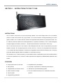
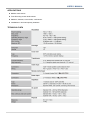
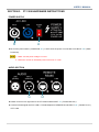
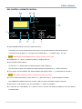
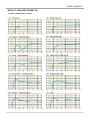
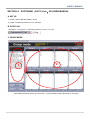
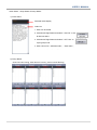
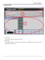
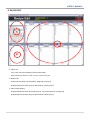
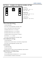
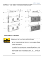
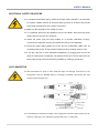
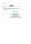
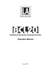
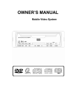
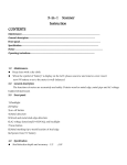
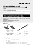
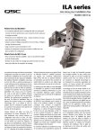
FT-1208 USER’S MANUAL FT-1208 WideLine – 8 Line Array / Self - Powered High power – to – size rati Integrayed DSP and remote control www.leestar.com.tw USER’S MANUAL CONTENTS SECTION 1. INTRODUCTION OF FT-1208...................................................... 2 INTRODUCTION FEATURES APPLICATIONS TECHNICAL DATA SECTION 2. SAFETY INSTRUCTIONS ............................................................ 4 IMPORTANT SAFETY INSTRUCTIONS SECTION 3. FT-1208 HARDWARE INSTRUCTIONS...................................... 5 POWER SUPPLY AUDIO SECTION DSP CONTROL & REMOTE CONTROL DEFAULT SPEAKERS PRESET EQ SECTION 4. SOFTWARE『PA PC-Link』GUI USER MANUAL .................... 8 A. SET UP B. START GUI C. GROUP MODE D. SINGLE MODE E. RECIPE EDIT SECTION 5. EXAMPLE OF REMOTE CONTROL SETTING ........................ 12 HOW TO CREATE NEW INDEX HOW TO MODIFY THE INDEX USE NEW INDEX WANT TO MONITOR LEFT SUBWOOFER SECTION 6. LINE ARRAY SYSTEM SUSPENSION SAFETY ...................... 13 SUSPENSION SAFETY WARNINGS INSPECTION & MAINTENANCE ELECTRICAL SAFETY PRACTICES XLR CONNECTOR 1 USER’S MANUAL SECTION 1. INSTRUCTIONS TO THE FT-1208 INSTRUCTIONS The FT-1208 is a self-power 2 way line array design speaker. In its ultra-compact sizes it has an incredible reserve of power that ensures very high pressure on its wide horizontal coverage,maintaining the sound quality constant. The FT-1208 is ideal for medium throw applications,like theatres,concert halls,churches. The FT-1208 low profile box allows also frontfill applications or corporate AV situations. The FT-1208 is designed to easily integrate with others products,for example with subwoofers or at the bottom of line array. The FT-1208 user two 8"inchs cone drivers for low-midfrequencies with 3"voice coil,powered by two power amplifier channels. The mid-high frequencies section uses two 1.75"voice coil compression drive,that drive 1"×4" constant directivity waveguides. The drives are integrated in the box with a fixed angle of 20°. The flying points with different degress allow the installation in curvilinear line arrays. The transducers of FT-1208 are driven by an internalDSP module, a dedicated remote control software allows to control the speaker from PC. All the FT-1208 components are designed by LEESTAR R&D department and custom. FEATURES Unique performance-to-size ratio. Integrated 35mm pole adapter. Self powered. Top quality components for outstanding Performances. Integrated DSP and remote control. Ultra fast set-up and dismantling system. Wide horizontal coverage. For use in stand alone arrays or in combination with other Very flat profile. Integrated flying hardware. systems. 2 USER’S MANUAL APPLICATIONS Medium scale events. Front fill touring sound reinforcement. Stadiums, theatres, concert halls, conferences. Installations in low-load capacity situations. TECHNICAL DATA 3 USER’S MANUAL SECTION 2. SAFETY INSTRUCTIONS IMPORTANT SAFETY INSTRUCTIONS The FT-1208 loudspeakers are not intended for fixed installation in outdoor or high moisture environments. Moisture can damage the speaker cone and surround and cause corrosion of electrical contacts and metal parts. Avoid exposing the speakers to direct moisture. Do not use this apparatus near water. To reduce the risk of fire or electric shock, do not expose this apparatus to rain or moisture. Unplug this apparatus during lightning storms or when unused for long periods of time. Do not expose this equipment to dripping or splashing and ensure that no objects filled with liquids,such as vases, are placed on the equipment. Clean only with dry cloth. Keep loudspeakers out of extended or intense direct sunlight. The driver suspension will prematurely dry out and finished surfaces may be degraded by long-term exposure to intense ultra-violet (UV) light. Do not install near any heat sources such as radiators, heat registers, stoves, or other apparatus (including amplifiers) that produce heat. When a cart is used, use caution when moving the cart /apparatus combination to avoid injury from tip-over. Loudspeakers are easily capable of generating sound pressure levels (SPL) sufficient to cause permanent hearing damage to performers, production crew and audience members. Caution should be taken to avoid prolonged exposure to SPL in excess of 90 dB. 4 USER’S MANUAL SECTION 3. FT-1208 HARDWARE INSTRUCTIONS POWER SUPPLY A B Be sure the power switch ( POWER ON “A” ) is OFF when the power is connected to AC INPUT “B” ( White PowerCon). 1、Make sure the power voltage is correct. 2、Maximum number of affordable power series is 8 FT-1208 AUDIO SECTION C D Please connect music signal line to the FT-1208’s AUDIO INPUT “C” ( Female Bal.XLR ). Connect RS-485 signal line from USB >> RS-485 Adapter to REMOTE RS-485 INPUT “D” ( Female RJ-45 ) of FT-1208. 5 USER’S MANUAL DSP CONTROL & REMOTE CONTROL M HG K J E F L I Adjust ADDRESS BCD, and set FT-1208’s Device ID. This setting can not be changed after power booting, this ID will be Address called when Remote. ( The left is set of ten digits “E” ; the right is set of single-digit “F”, Address range:00 ~ 99 ) Avoid set the same ADDRESS when using more than one FT-1208. POWER LED “G” ( Green ) will light up when FT-1208’s power on. Inpute signal LEVEL Adapter : If Limit LED “H” ( Yellow ) light up,meaning input too large ( Clipping ), You can make the input music signal be suitable weaken throught this VR “I” ( INPUT PAD dB ). If you need to convert PRESET EQ, adjust PRESET EQ SELECT BCD “J ”.( Preset EQ has 10 kinds.) This feature will be stop when FT-1208 Remote Control is used. Lock FT-1208 Preset settings : When locked “K” ( after click LOCK ),LCM will display “LOCKED”, then PRESET EQ SELECT will have no effect, untill you press LOCK button again to stop lock. When the FT-1208 abnormal, you can click RESET “L” button to reset DSP. FT-1208 has one LCM display “M ”( 8-word 2 rows ), the first row display ID Address, the lower display Preset EQ state. 6 USER’S MANUAL DEFAULT SPEAKERS PRESET EQ FT-1208 PRESET EQ 10 models : 7 USER’S MANUAL SECTION 4. SOFTWARE『PA PC-Link』GUI USER MANUAL A. SET UP 1) Install “ USB To RS-485 Adapter ” Driver 2) Install “ Professional Audio PC Link ” Software B. START GUI Start Menu >> Programs >> Professional Audio PC-Link >> PC-Link C. GROUP MODE 1 2 3 1 More detail information about (1) Index Select、(2) Group Status will be described on next Page. 8 USER’S MANUAL Index Select、Group Status of Group Mode : 1) Index Select Selected Index Display Index List 1. Index can be sorted 2. Click Mouse Right Button and select ” ON-Link ” to set all devices status 3. Click Mouse Right Button and select ” OFF-Link ” to reject group mode 4. Index List can be “ Add New Index ”, “ Save Index ”, “ Delete Index ” by “ Recipe Edit ”. 2) Group Status Show the index setting, when ON-Link success, preset row will blinking. 9 USER’S MANUAL D. SINGLE MODE 1 2 3 1 1) Device Select: Monitor the device status, ID is follow index setting. 2) Device Status: Device Status Information, Include Device Picture, Temperature, Output Level, Preset Curve. Also can control device Preset select, Mute, Lock. 10 USER’S MANUAL E. RECIPE EDIT 1 3 1 2 1 1) Index List: Select index can see the setting of each index status. Click mouse right button to “Add”, “Save”or “Delete”the Index. 2) Device List: Unused device ID list can multi-select, drag-drop to group in. Drag-drop device ID from group to device list for cancel group in. 3) Index Group Setting: Drag-drop device ID from device list to group, can set the device in to the group Drag-drop device ID from group to device list for cancel group in. 11 USER’S MANUAL SECTION 5. EXAMPLE OF REMOTE CONTROL ETTING Left Array: Full Range x 8 ( ID:0 ~ 7 ) Sub x 1 ( ID:50 ) Right Array: Full Range x 8 ( ID:10 ~ 17 ) Sub x 1 ( ID:60 ) Center Array: Full Range x 4 ( ID:20~ 23) How to Create New Index? 1) Select Recipe Edit 2) At Index List Click Right Button And Select “Add” 3) Key In Index Name to top of Index List Row 4) Drag-Drop Device ID 0 ~7 In To Group 1 5) Drag-Drop Device ID 10 ~17 In To Group 2 6) Drag-Drop Device ID 20 ~23 In To Group 3 7) Drag-Drop Device ID 50 and ID 60 In To Group 4 8) Set Group1、2、3、4 Preset 9) At Index List Click Right Button And Select “Save” How to Modify The Index? 1) Select Recipe Edit 2) Modify What You Want, Group In, Cancel Group, Change Preset 3) At Index List Click Right Button And Select “Save” Use New Index 1) Create New Index 2) Select Group Mode 3) Select Index From Index List And Click Right Button Select “ON-Link” Want To Monitor Left Subwoofer? 1) Select Single Mode 2) Can Be Selected Device ID Buttons is 0~7, 10~17, 50 And 60 3) Click ID 50 Button To Monitor Left Subwoofer 12 USER’S MANUAL SECTION 6. LINE ARRAY SYSTEM SUSPENSION SAFETY SUSPENSION SAFETY WARNINGS Speaker can be used with an optional accessory allowing mounting on a pole over subwoofers. When using, be sure to observe the following precautions: Inspect the pole and associated hardware before each use . Do not use equipment with worn, damaged, or missing parts. Correct use of all rigging hardware is required for secure system suspension. Check the pole specification to be certain the device is designed to support the weight of the speaker. Careful calculations should always be performed to ensure that all components are used within their Maximum Load Limit before the array is suspended. Never exceed the maximum recommended load ratings. Prior to suspending the system, an expert, trained and experienced in flying speaker systems should be consulted. 13 USER’S MANUAL Avoid attaching banners or similar items to any part of a speaker system. Such attachments could act as a sail and topple the system. Research and understand the codes, practices, and requirements in the venues where you intend to operate your sound system. Route cables so that performers, production crew, and audience will not trip over them and pull the speaker over. INSPECTION & MAINTENANCE Before suspending or pole mounting any speaker system always inspect all components (enclosure, rigging frames, pins, eyebolts, track fittings, etc.) for cracks, deformations, corrosion, missing, loose or damaged parts that could reduce strength and safety of the array. Do not suspend or pole mount the speaker until the proper corrective action has been taken. Installed systems should be inspected at least annually. The inspection shall include a visual survey of all corners and load bearing surfaces for signs of cracking, water damage , de-lamination , or any other condition that may decrease the strength of the loudspeaker enclosure. 14 USER’S MANUAL ELECTRICAL SAFETY PRACTICES In compliance with safety agency criteria and proper system operation, it is critical that the system installer observe all electrical safety practices at all times and provide proper earth grounding for all AC Power connections. Make sure the selected AC line voltage is correct. To completely disconnect this apparatus from the AC Mains, disconnect the power supply cord plug from the AC receptacle. Protect the power cord from being walked on or pinched, particularly at plugs, convenience receptacles, and the point where they exit from the apparatus. Check the signal cable between the mixer and the loudspeaker. Make sure all connections are secure. These problems usually produce crackling noises or hum. If you are using two or more powered loudspeakers, try plugging them all into the same AC outlet panel or outlet strip. The purpose for this is to connect them all to the same earth ground point and reduce the possibility of creating a ground loop. XLR CONNECTOR XLR connectors are used to make balanced input and through connections to the loudspeaker. They are wiredas follows, according to standards specified by the AES (Audio Engineering Society). If connecting an unbalanced output to the loudspeakers balanced input, make sure the shield is connected to the unbalanced ground and to pin 1 of the XLR. 15 USER’S MANUAL FT-1208 www.leestar.com.tw 16