1
Pt 100 Temperature Input Module Type AJ65BT64RD3/AJ65BT-64RD4 User's Manual
SAFETY PRECAUTIONS
(Read these precautions before using this product.)
Before using this product, please read this manual and the relevant manuals carefully and pay full
attention to safety to handle the product correctly.
These precautions apply only to Mitsubishi equipment.
Refer to the user's manual of the used CPU
module for a description of the programmable controller system safety precautions.
In this manual, the safety precautions are classified into two levels: "
WARNING" and "
CAUTION".
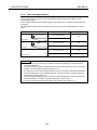
WARNING
Indicates that incorrect handling may cause hazardous conditions,
resulting in death or severe injury.
CAUTION
Indicates that incorrect handling may cause hazardous conditions,
resulting in minor or moderate injury or property damage.
Under some circumstances, failure to observe the precautions given under "
CAUTION" may lead to
serious consequences.
Observe the precautions of both levels because they are important for personal and system safety.
Make sure that the end users read this manual and then keep the manual in a safe place for future
reference.
[Design Precautions]
WARNING
z
In the case of a communication failure in the network, data in the master module are held.
Check the communication status information (SB, SW) and configure an interlock circuit in the sequence
program to ensure that the entire system will operate safely.
CAUTION
z
Do not install the control lines or communication cables together with the main circuit lines or power cables.
Keep a distance of 100mm (3.94 inches) or more between them.
Failure to do so may result in malfunction due to noise.
[Installation Precautions]
CAUTION
z
Use the programmable controller in an environment that meets the general specifications in this manual.
Failure to do so may result in electric shock, fire, malfunction, or damage to or deterioration of the product.
z
For protection of the switches, do not remove the cushioning material before installation.
z
Securely fix the module with a DIN rail or mounting screws. Tighten the screws within the specified torque
range.
Undertightening can cause drop of the screw, short circuit or malfunction.
Overtightening can damage the screw and/or module, resulting in drop, short circuit, or malfunction.
z
Do not directly touch any conductive part of the module.
Doing so can cause malfunction or failure of the module.
[Wiring Precautions]
CAUTION
z
Shut off the external power supply for the system in all phases before wiring.
Failure to do so may result in damage to the product.
z
After installation or wiring, attach the included terminal cover to the module before turning it on for operation.
Undertightening can cause short circuit or malfunction.
z
Ground the FG terminals to the protective ground conductor dedicated to the programmable controller.
Failure to do so may result in malfunction.
z
Use applicable solderless terminals and tighten them within the specified torque range.
If any spade solderless terminal is used, it may be disconnected when the terminal screw comes loose,
resulting in failure.
z
Check the rated voltage and terminal layout before wiring to the module, and connect the cables correctly.
Connecting a power supply with a different voltage rating or incorrect wiring may cause a fire or failure.
z
Tighten the terminal screw within the specified torque range.
Undertightening can cause short circuit or malfunction.
Overtightening can damage the screw and/or module, resulting in drop, short circuit, or malfunction.
z
Prevent foreign matter such as dust or wire chips from entering the module.
Such foreign matter can cause a fire, failure, or malfunction.
z
Place the cables in a duct or clamp them.
If not, dangling cable may swing or inadvertently be pulled, resulting in damage to the module or cables or
malfunction due to poor contact.
[Wiring Precautions]
CAUTION
z
Do not install the control lines or communication cables together with the main circuit lines or power cables.
Failure to do so may result in malfunction due to noise.
z
When disconnecting the cable from the module, do not pull the cable by the cable part.
Loosen the screws of connector before disconnecting the cable.
Failure to do so may result in damage to the module or cable or malfunction due to poor contact.
[Startup and Maintenance Precautions]
CAUTION
z
Do not touch any terminal while power is on.
Doing so may cause malfunction.
z
Shut off the external power supply for the system in all phases before cleaning the module or retightening
the terminal screws.
Failure to do so may cause the module to fail or malfunction.
Undertightening the terminal screws can cause short circuit or malfunction.
Overtightening can damage the screw and/or module, resulting in drop, short circuit, or malfunction.
z
Do not disassemble or modify the modules.
Doing so may cause failure, malfunction, injury, or a fire.
z
Do not drop or apply strong shock to the module.
Doing so may damage the module.
z
After the first use of the product, do not mount/remove the terminal block to/from the module more than 50
times. (IEC 61131-2 compliant)
z
Shut off the external power supply for the system in all phases before mounting or removing the module to
or from the panel.
Failure to do so may cause the module to fail or malfunction.
z
Do not remove or change the platinum temperature-measuring resistor designation pin while energizing the
module.
If a platinum temperature-measuring resistor designation pin is removed or changed while energizing, it may
cause failure or malfunction.
z
Before handling the module, touch a grounded metal object to discharge the static electricity from the
human body.
Failure to do so may cause the module to fail or malfunction.
[Disposal Precautions]
CAUTION
z
When disposing of this product, treat it as an industrial waste.
CONDITIONS OF USE FOR THE PRODUCT
(1) Mitsubishi programmable controller ("the PRODUCT") shall be used in conditions;
i) where any problem, fault or failure occurring in the PRODUCT, if any, shall not lead to any major or
serious accident; and
ii) where the backup and fail-safe function are systematically or automatically provided outside of the
PRODUCT for the case of any problem, fault or failure occurring in the PRODUCT.
(2) The PRODUCT has been designed and manufactured for the purpose of being used in general
industries.
MITSUBISHI SHALL HAVE NO RESPONSIBILITY OR LIABILITY (INCLUDING, BUT NOT LIMITED
TO ANY AND ALL RESPONSIBILITY OR LIABILITY BASED ON CONTRACT, WARRANTY, TORT,
PRODUCT LIABILITY) FOR ANY INJURY OR DEATH TO PERSONS OR LOSS OR DAMAGE TO
PROPERTY CAUSED BY the PRODUCT THAT ARE OPERATED OR USED IN APPLICATION
NOT INTENDED OR EXCLUDED BY INSTRUCTIONS, PRECAUTIONS, OR WARNING
CONTAINED IN MITSUBISHI'S USER, INSTRUCTION AND/OR SAFETY MANUALS, TECHNICAL
BULLETINS AND GUIDELINES FOR the PRODUCT.
("Prohibited Application")
Prohibited Applications include, but not limited to, the use of the PRODUCT in;
y Nuclear Power Plants and any other power plants operated by Power companies, and/or any other
cases in which the public could be affected if any problem or fault occurs in the PRODUCT.
y Railway companies or Public service purposes, and/or any other cases in which establishment of a
special quality assurance system is required by the Purchaser or End User.
y Aircraft or Aerospace, Medical applications, Train equipment, transport equipment such as Elevator
and Escalator, Incineration and Fuel devices, Vehicles, Manned transportation, Equipment for
Recreation and Amusement, and Safety devices, handling of Nuclear or Hazardous Materials or
Chemicals, Mining and Drilling, and/or other applications where there is a significant risk of injury to
the public or property.
Notwithstanding the above, restrictions Mitsubishi may in its sole discretion, authorize use of the
PRODUCT in one or more of the Prohibited Applications, provided that the usage of the PRODUCT is
limited only for the specific applications agreed to by Mitsubishi and provided further that no special
quality assurance or fail-safe, redundant or other safety features which exceed the general
specifications of the PRODUCTs are required. For details, please contact the Mitsubishi
representative in your region.
Revisions
* The manual number is noted at the lower left of the back cover.
Print Date
*Manual Number
May., 1998
SH(NA)-4001-A
Oct., 2004
SH(NA)-4001-B
Revision
First printing
Partial correction
SAFETY PRECAUTIONS,
Chapter 1, Section 2.1, 2.2, 3.1, 3.2, 3.2.2, 3.3.1, 3.3.4, 3.4.1, 3.4.2, 3.5.1,
Section 4.1, 4.2, 4.3, 4.5, 4.7.1, 4.7.2, Chapter 5, Section 5.1, 5.2, 6.1,
Addition
Conformation to the EMC Directive and Low Voltage Instruction, About
Manual, About the Generic Terms and Abbreviations, Product Structure,
Section 5.3, 5.4, 5.5, 5.6, WARRANTY
Deletion
Chapter 3, Section 5.2.1,
Jul., 2005
SH(NA)-4001-C
Partial correction
SAFETY PRECAUTIONS
Dec., 2006
SH(NA)-4001-D
Partial correction
SAFETY PRECAUTIONS, Section 2.1, 3.2, 3.6.1, 3.7.4, 4.1
Dec., 2010
SH(NA)-4001-E
Partial correction
SAFETY PRECAUTIONS, Compliance with the EMC and Low Voltage
Directives, About Generic Terms and Abbreviations, Chapter 1, Section 2.1,
2.2, 3.1, 3.2, 3.2.2, 3.4.1, 4.2, 4.7.4, 5.2, 5.3, 5.6, 6.1, 6.4
Addition
CONDITIONS OF USE FOR THE PRODUCT
Deletion
Section 4.7.1
Renumbering
Section 4.7.2 to 4.7.5 → 4.7.1 to 4.7.4
Japanese Manual Version SH-3652-G
This manual does not imply guarantee or implementation right for industrial ownership or implementation
of other rights. Mitsubishi Electric Corporation is not responsible for industrial ownership problems caused
by use of the contents of this manual.
© 1998 Mitsubishi Electric Corporation
Introduction
Thank you for purchasing the Mitsubishi Graphic Operation Terminal.
Before using the equipment, please read this manual carefully to develop full familiarity with the functions and
performance of the graphic operation terminal you have purchased, so as to ensure correct use.
Please forward a copy of this manual to the end user.
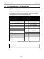
Table of Contents
1.
OVERVIEW
1.1
Features............................................................................................................................................................ 1- 1
2.
SYSTEM CONFIGURATION
2.1
2.2
Overall Configuration ........................................................................................................................................ 2- 1
Applicable Systems........................................................................................................................................... 2- 2
3.
SPECIFICATIONS
3.1
3.2
General Specification........................................................................................................................................ 3- 1
Performance Specification ................................................................................................................................ 3- 2
3.2.1 Specifications when connecting to a platinum temperature-measuring resistor.................................... 3- 3
3.2.2 Data link processing time....................................................................................................................... 3- 4
Function ............................................................................................................................................................ 3- 5
3.3.1 Function list............................................................................................................................................ 3- 5
3.3.2 Conversion enable/disable designation ................................................................................................. 3- 6
3.3.3 Sampling processing/travel average processing designation................................................................ 3- 7
3.3.4 Wire breakage detection........................................................................................................................ 3- 9
3.3.5 Detected temperature ............................................................................................................................ 3-10
3.3.6 Designating the platinum temperature-measuring resistor type ............................................................ 3-10
I/O Signals in Respect to the Master Module.................................................................................................... 3-11
3.4.1 Remote I/O signal list............................................................................................................................. 3-11
3.4.2 I/O signal functions ................................................................................................................................ 3-12
Remote Register ............................................................................................................................................... 3-14
3.5.1 Remote register assignment.................................................................................................................. 3-14
3.5.2 Remote register for storing detected temperature (Address: RWrn to RWrn+11)................................. 3-15
3.3
3.4
3.5
1-1 to 1-1
2-1 to 2-2
3-1 to 3-15
4.
SETTING AND PROCEDURE BEFORE OPERATION
4.1
4.2
4.3
4.4
Procedure before Operation ............................................................................................................................. 4Handling Precautions........................................................................................................................................ 4Part Identification and Setting ........................................................................................................................... 4Error Compensation by the Offset Value/Gain Value Setting ........................................................................... 44.4.1 Initial settings for error compensation.................................................................................................... 44.4.2 Error compensation procedure .............................................................................................................. 4Station Number Setting..................................................................................................................................... 4Orientation of Module Installation ..................................................................................................................... 4-
4.5
4.6
4-1 to 4-12
1
2
3
5
7
8
9
9
4.7
Wiring................................................................................................................................................................ 4-10
4.7.1 Wiring example with CC-Link modules .................................................................................................. 4-10
4.7.2 Precautions when wiring to a platinum temperature-measuring resistor ............................................... 4-11
4.7.3 Connecting AJ65BT-64RD3 and platinum temperature-measuring resistor.......................................... 4-11
4.7.4 Connecting AJ65BT-64RD and platinum temperature-measuring resistor............................................ 4-12
5.
PROGRAMMING
5.1
5.2
5.3
5.4
5.5
5.6
Programming Procedure................................................................................................................................... 5- 1
Program Example Conditions ........................................................................................................................... 5- 2
Program Examples when QCPU (Q Mode) Is Used ......................................................................................... 5- 5
Program Examples when QnACPU Is Used ..................................................................................................... 5-11
Program Example when ACPU/QCPU (A Mode) Is Used (Dedicated Instructions).......................................... 5-13
Program Example when ACPU/QCPU (A Mode) Is Used (FROM/TO Instructions).......................................... 5-16
6.
TROUBLESHOOTING
6.1
6.2
6.3
6.4
6.5
6.6
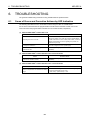
Cause of Errors and Corrective Actions by LED Indication............................................................................... 6When Wire Breakage Detection Flag is On ...................................................................................................... 62
When E PROM Error Flag is On....................................................................................................................... 6When Detected Temperature Value cannot be Read ....................................................................................... 6When Detected Temperature Value is Abnormal ............................................................................................. 6When There is a Communication Error between Master Station and AJ65BT-64RD....................................... 6-
APPENDIX
5-1 to 5-17
6-1 to 6-5
1
3
3
3
3
4
A-1 to A-2
Appendix 1
Standard Thermal Electromotive Force of Platinum Temperature-Measuring Resistor ..................... AAppendix 1.1
New JIS⋅IEC type (Pt100)....................................................................................................... AAppendix 1.2
Old JIS type (JPt100).............................................................................................................. AAppendix 2
External Dimensions Diagram ............................................................................................................ A-
1
1
1
2
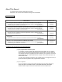
About This Manual
The following are manuals related to this product.
Request for the manuals as needed according to the chart below.
Related Manuals
Manual Name
CC-Link System Master/Local Module Type AJ61BT11/A1SJ61BT11 User's Manual
Describes the system configuration, performance specifications, functions, handling, wiring and
troubleshooting of the AJ61BT11 and A1SJ61BT11.
(Sold separately)
CC-Link System Master/Local Module Type AJ61QBT11/A1SJ61QBT11 User's Manual
Describes the system configuration, performance specifications, functions, handling, wiring and
troubleshooting of the AJ61QBT11 and A1SJ61QBT11.
(Sold separately)
CC-Link System Master/Local Module User's Manual
Describes the system configuration, performance specifications, functions, handling, wiring and
troubleshooting of the QJ61BT11N.
(Sold separately)
Programming Manual type AnSHCPU/AnACPU/AnUCPU/QCPU-A (A Mode) (Dedicated
Instructions)
Explains the instructions extended for the AnSHCPU/AnACPU/AnUCPU/QCPU-A (A Mode).
(Sold separately)
MELSEC-L CC-Link System Master/Local Module User's Manual
Describes the system configuration, Performance specifications, functions, handling, wiring and
troubleshooting of the L26CPU-BT and LJ61BT11.
(Sold separately)
Manual Number
(Model Code)
IB-66721
(13J872)
IB-66722
(13J873)
SH-080394E
(13JR64)
IB-66251
(13J742)
SH-080895ENG
(13JZ41)
Compliance with the EMC and Low Voltage Directives
(1) For programmable controller system
To configure a system meeting the requirements of the EMC and Low Voltage
Directives when incorporating the Mitsubishi programmable controller (EMC and
Low Voltage Directives compliant) into other machinery or equipment, refer to the
"EMC AND LOW VOLTAGE DIRECTIVES" chapter of the User's Manual for the
CPU module used.
The CE mark, indicating compliance with the EMC and Low Voltage Directives, is
printed on the rating plate of the programmable controller.
(2) For the product
For the compliance of this product with the EMC and Low Voltage Directives,
refer to the "CC-Link module" section in the "EMC AND LOW VOLTAGE
DIRECTIVES" chapter of the User's Manual for the CPU module used.
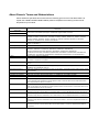
About Generic Terms and Abbreviations
Unless otherwise specified, this manual uses the following generic terms and abbreviations to
explain the AJ65BT-64RD3/AJ65BT-64RD4 platinum temperature-measuring resistor Pt100
temperature input module.
Generic Term/
Abbreviation
GX Developer
GX Works2
Description
Product name of the software package for the MELSEC programmable controllers.
ACPU
Generic term for A0J2CPU, A0J2HCPU, A1CPU, A2CPU, A2CPU-S1, A3CPU, A1SCPU, A1SCPUC24-R2,
A1SHCPU, A1SJCPU, A1SJCPU-S3, A1SJHCPU, A1NCPU, A2NCPU, A2NCPU-S1, A3NCPU, A3MCPU,
A3HCPU, A2SCPU, A2SHCPU, A2ACPU, A2ACPU-S1, A3ACPU, A2UCPU, A2UCPU-S1, A2USCPU,
A2USCPU-S1, A2USHCPU-S1, A3UCPU and A4UCPU.
QnACPU
Generic term for Q2ACPU, Q2ACPU-S1, Q2ASCPU, Q2ASCPU-S1, Q2ASHCPU, Q2ASHCPU-S1, Q3ACPU,
Q4APU and Q4ARCPU.
QCPU (A mode)
Generic term for Q02CPU-A, Q02HCPU-A and Q06HCPU-A.
QCPU (Q mode)
Generic term for Q00JCPU, Q00CPU, Q01CPU, Q02CPU, Q02HCPU, Q06HCPU, Q12HCPU, Q25HCPU,
Q02PHCPU, Q06PHCPU, Q12PHCPU, Q25PHCPU, Q12PRHCPU, Q25PRHCPU,
Q00UJCPU,Q00UCPU,Q01UCPU,Q02UCPU, Q03UDCPU, Q04UDHCPU, Q06UDHCPU,
Q10UDHCPU,Q13UDHCPU, Q20UDHCPU,Q26UDHCPU, Q03UDECPU, Q04UDEHCPU, Q06UDEHCPU,
Q10UDEHCPU, Q13UDEHCPU, Q20UDEHCPU, Q26UDEHCPU,Q50UDEHCPU and Q100UDEHCPU.
LCPU
Generic term for L02CPU, L26CPU-BT.
Master station
Station that controls a data link system.
One station is required for one system.
Local station
Remote I/O station
Station that has a programmable controller CPU and can communicate with the master station and other local
stations.
Station that handles only bit unit information. (Input/output from/to external device)
(AJ65BTB1-16D, AJ65SBTB1-16D, etc.)
Remote device station
Station that handles bit unit information and word unit information. (Input/output from/to external device, analog
data conversion)
Remote station
Generic term for remote I/O station and remote device station. Controlled by the master station.
Intelligent device station
Station that can perform transient transmission, e.g. AJ65BT-R2. (Local station included)
Master module
Generic term for modules that can be used as the master station.
SB
Link special relay (for CC-Link)
Bit unit information that indicates the module operation status or data link status of the master station/local
station. Represented as SB for convenience.
SW
Link special register (for CC-Link)
16-bit unit information that indicates the module operation status or data link status of the master station/local
station. Represented as SW for convenience.
RX
Remote input (for CC-Link)
Information input from a remote station to the master station in bit unit. Represented as RX for convenience.
RY
Remote output (for CC-Link)
Information output from the master station to a remote station in bit unit. Represented as RY for convenience.
RWw
Remote register (write area for CC-Link)
Information output from the master station to a remote device station in 16-bit unit. Represented as RWw for
convenience.
RWr
Remote register (read area for CC-Link)
Information input from a remote device station to the master station in 16-bit unit. Represented as RWr for
convenience.
Packing List
This product consists of the following items.
Product name
AJ65BT-64RD3 platinum temperature-measuring resistor Pt100 temperature input module
Quantity
1
AJ65BT-64RD4 platinum temperature-measuring resistor Pt100 temperature input module
AJ65BT-64RD3/AJ65BT-64RD4 platinum temperature-measuring resistor Pt100 temperature input module
user's manual (hardware)
1
MEMO
1. OVERVIEW
1.
MELSEC-A
OVERVIEW
This user's manual explains the specifications, part identification and wiring for the products listed
below, which are used as remote device stations for the CC-Link system:
The AJ65BT-64RD3 is a 3-wire system connecting module for the platinum temperature-measuring
resistor.
The AJ65BT-64RD4 is a 4-wire system connecting module for the platinum temperature-measuring
resistor.
(Hereinafter, the AJ65BT-64RD3 and AJ65BT-64RD4 will be collectively referred to as AJ65BT-64RD.)
The AJ65BT-64RD converts temperature data input from platinum temperature-measuring resistor Pt
100 (abbreviated as Pt 100 from here on) or platinum temperature-measuring resistor JPt 100
(abbreviated as JPt 100 from here on) to 16-bit signed BIN data (up to the first decimal place), or 32bit signed BIN data (up to the third decimal place).
1.1
Features
The following describes the features of AJ65BT-64RD.
(1) Stores temperature data
By directly connecting the old JIS or new JIS IEC type platinum temperature-measuring resistor
to AJ65BT-64RD, temperature data [°C] may be received as digital values.
For the detected temperature, values to the first place and third place below decimal point are
stored in the remote register.
(2) Conversion is possible at four channels per module.
Conversion of temperatures into digital values can be carried out at four channels in a single
AJ65BT-64RD module.
Also, the conversion enable/disable can be specified for individual channels.
(3) Designation of sampling processing and travel average processing
As a conversion method, either sampling processing or travel averaging processing can be
selected for each channel.
(4) Wire breakage detection is possible at individual channels.
The wire breakage of platinum temperature-measuring resistor or cable can be detected for each
channel.
(5) High overall accuracy
High-accuracy temperature detection is feasible with a tolerance of ±0.25 % of the full scale in
overall accuracy for normal temperature detection, and ±0.1 % of the full scale when the ambient
temperature is in the normal temperature range (25 °C ±5 °C).
1-1
2.
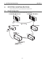
2.
SYSTEM CONFIGURATION
MELSEC-A
SYSTEM CONFIGURATION
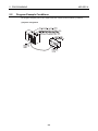
System configuration when using the AJ65BT-64RD is explained below.
2.1
Overall Configuration
The overall configuration when using the AJ65BT-64RD is shown below.
2-1
2.
2.2
SYSTEM CONFIGURATION
MELSEC-A
Applicable Systems
This section explains applicable systems.
(1)
Applicable master modules
For available master modules, visit the CC-Link Partner Association (CLPA) website at:
http://www.cc-link.org/
REMARK
Check the specifications of the master module before use.
POINT
When using the AJ61BT11, A1SJ61BT11, AJ61QBT11 or A1SJ61QBT11, use the one where the
following number (9707 B or later) is indicated in the DATE column of the rating plate.
The module where "9707 B" is not indicated in the DATE column cannot be used.
<Large type>
<Small type>
MITSUBISHI
PROGRAMMABLE CONTROLLER
DATE
9707
CPU UNIT
MODEL
DATE
B
9707
B
MITSUBISHI ELECTRIC CORPORATION JAPAN
BD992D008H40
Date of
manufacture
(2)
Function
version
MITSUBISHI ELECTRIC
Date of
manufacture
BD992D008H40
Function
version
Restrictions on use of CC-Link dedicated instructions (RLPA, RRPA)
The CC-Link dedicated instructions (RLPA, RRPA) may be inapplicable depending on the used
programmable controller CPU and master module.
For details of the restrictions, refer to the A series master module user's manual (details) or
AnSHCPU/AnACPU/AnUCPU/QCPU-A (A mode) programming manual (dedicated instructions).
The AJ65BT-64RD accepts only the dedicated instructions RLPA and RRPA.
Refer to Section 5.5 for a program example that uses the dedicated instructions (RLPA, RRPA).
2-2
3. SPECIFICATIONS
3.
MELSEC-A
SPECIFICATIONS
This section explains the AJ65BT-64RD the general specifications, performance specifications, and
transmission specifications.
3.1
General Specification
This section explains the AJ65BT-64RD general specifications.
Table 3.1 General Specification
Item
Specifications
Ambient operating
temperature
0 to 55 °C
-20 to 75 °C
Ambient storage temperature
Ambient operating humidity
10 to 90 %RH, Non-condensing
Ambient storage humidity
10 to 90 %RH, Non-condensing
For intermittent
Conforming to vibration
JIS B 3502,
IEC 61131-2
For continuous
vibration
Vibration resistance
Shock resistance
Frequency
Acceleration
Amplitude
5 to 9 Hz
—
3.5mm
(0.14inches)
9 to 150 Hz
9.8 m/s2
—
5 to 9 Hz
—
1.75mm
(0.069inches)
9 to 150 Hz
4.9 m/s2
—
No. of sweeps
10 times in each
direction X, Y, Z
—
Conforming to JIS B 3502, IEC 61131-2
(147 m/s2, 3 times in each of 3 directions X Y Z)
Operating ambience
No corrosive gases
Operating elevation *3
2000 m (6562 ft.) max.
Installation location
Control panel
Over voltage category *1
II max.
Pollution level *2
2 max.
*1 : This indicates the section of the power supply to which the equipment is assumed to be
connected between the public electrical power distribution network and the machinery within the
premises. Category II applies to equipment for which electrical power is supplied from fixed
facilities. The surge voltage withstand level for up to the rated voltage of 300 V is 2500 V.
*2 : This index indicates the degree to which conductive material is generated in terms of the
environment in which the equipment is used. Pollution level 2 is when only non-conductive
pollution occurs. A temporary conductivity caused by condensation must be expected
occasionally.
*3 : Do not operate or store the programmable controller in the environment where the pressure
applied is equal to greater than the atmospheric pressure at the altitude of 0m. Doing so may
cause a malfunction. Please consult our branch office when the programmable controller is to be
operated under pressure.
3-1
3. SPECIFICATIONS
3.2
MELSEC-A
Performance Specification
The performance specification of the AJ65BT-64RD is explained below.
Item
Measurement method
AJ65BT-64RD3
AJ65BT-64RD4
3-wire
4-wire
Connectable platinum temperaturemeasuring resistor
Pt 100, JPt 100
1 mA
Output current for detecting temperature
Temperature input range
–180 to 600 °C
16-bit signed binary : –1800 to 6000
(value to one decimal place × 10)
Temperature detection
value
Overall
accuracy
32-bit signed binary : –180000 to 600000
(value to three decimal places × 1000)
Operating ambient
temperature
(25 ± 5 °C)
± 0.1 % (accuracy for maximum value)
Operating ambient
temperature (less than
20 °C, more than 30
°C)
± 0.25 % (accuracy for maximum value)
Resolution
0.025 °C
Conversion speed (Sampling time)
40 ms/channel *1
Temperature input point
4-channel/module
CC-Link station type
Remote device station
4-station :
Occupied points
Dielectric withstand voltage
Insulation method
Insulation resistor
128 points each
RWw/RWr 16 points each
CC-Link dedicated cable
Connection cable
Noise durability
RX/RY
Noise voltage 500 Vp-p, Noise width 1 μs by noise simulator of the noise frequency 25 to 60 Hz
Between batch of power supply system and ground
Between batch of power supply system and batch of communication system
Between batch of communication system and batch of temperature input
Between batch of temperature input and ground
500V AC 1 minute
Between the platinum temperature-measuring
resistor input and CC-Link transmission: Photocoupler insulation
Between the platinum temperature-measuring
resistor input and channel: no insulation
Between batch of power supply system and ground
Between batch of power supply system and batch of communication system
Between batch of communication system and batch of temperature input
Between batch of temperature input and ground
500 V DC, 10MΩ or more on the insulation resistance tester
Connection terminal block
27-point terminal block (M3.5 × 7 screws)
0.75 to 2.00 mm2
Supported cable size
Supported solderless terminal
RAV 1.25-3.5, RAV 2-3.5 (Conform to JIS C 2805)
Module installation screw
M4 × 0.7 mm (0.03 in.) × 16 mm (0.63 in.) or more
Installation in the rail is possible, too.
TH 35-7.5 Fe, TH 35-7.5 Al, TH 35-15 Fe
(conform to JIS C 2812)
Applicable DIN rail
3-2
3. SPECIFICATIONS
MELSEC-A
Performance specification (continued)
Item
AJ65BT-64RD3
External power supply
AJ65BT-64RD4
24 V DC (18 to 30 V DC)
Internal consumed current
0.17 A (at 24VDC)
Allowable momentary power failure
period
1ms
Weight
0.38 (0.84) kg (lb.)
*1 : Conversion speed is the time until it is converted to the corresponding digital value after the
temperature has been input, and then stored in the remote register.
When the multiple channels are used, the conversion speed is “40 ms × number of the
conversion enable channels”
3.2.1
Specifications when connecting to a platinum temperature-measuring
resistor
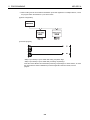
The following explains the specifications when connecting the AJ65BT-64RD and a platinum
temperature-measuring resistor.
(1) • The effect on the measured resistance by the discrepancy in the lead resistance value
connected to A, b is approximately
0.025 °C/10 m Ω.
• The lead resistance value between platinum temperature-measuring resistor and AJ65BT64RD3 should be 100 Ω or less per line.
AJ65BT-64RD3
100 Ω or less per line
A
Platinum temperaturemeasuring resistor
B
b
SLD
(2) The lead resistance value between between platinum temperature-measuring resistor and
AJ65BT-64RD4 should be 100 Ω or less per line.
AJ65BT-64RD4
100 Ω or less per line
a
A
Platinum temperaturemeasuring resistor
B
b
SLD
3-3
3. SPECIFICATIONS
3.2.2
MELSEC-A
Data link processing time
For the AJ65BT-64RD, the data link processing time shown below will be required in order to execute
each function.
For details of the link scan time, refer to the user's manual (details) of the used mater module.
Example) Data link processing time in asynchronous mode when the master module is the QJ61BT11
(normal value)
(1) Mater station (RY) → Remote device station (RY) processing time
[Expression]
SM + LS × 1 + Remote device station processing time [ms]
SM : Master station sequence program scan time
LS : Link scan time
Remote device station processing time: 1ms
(2) Master station (RX) ← Remote Device Station (RX) Processing Time
[Expression]
SM + LS × 1 + Remote device station processing time [ms]
SM : Master station sequence program scan time
LS : Link scan time
Remote device station processing time: (Number of used channels +1*) ×40ms
*: Internal processing time of AJ65BT-64RD
(3) Master station (RWr) ← Remote Device Station (RWr) Processing Time
[Expression]
SM + LS × 1 + Remote device station processing time [ms]
SM : Master station sequence program scan time
LS : Link scan time
Remote device station processing time: (Number of used channels +1*) ×40ms
*: Internal processing time of AJ65BT-64RD
POINT
The above are examples of processing time until the control of the output signal to the AJ65BT64RD from the programmable controller CPU or until input signals or remote registers are read.
The maximum time that takes for updating the detected temperature read by the programmable
controller CPU is “data link processing time + sampling time.”
3-4
3. SPECIFICATIONS
3.3
MELSEC-A
Function
The function of AJ65BT-64RD is explained below.
3.3.1
Function list
Below is a function list of the AJ65BT-64RD.
Item
Conversion enable/disable
designation
Description
• Performs conversion enable/disable settings by channel.
(Default ······ All channels disabled)
• Sampling time may be reduced by disabling the conversion
at channels not in use.
Reference section
Section 3.3.2
Sampling processing/travel
average processing designation
• Designates sampling processing or travel average
processing by channel.
(Default ······ All channels sampling processing)
Section 3.3.3
Wire breakage detection
• Detects wire breakage for the connected thermocouple by
channel.
Section 3.3.4
Detected temperature storage
• A value to one decimal place (16-bit signed binary) will be
stored in the remote register.
Section 3.3.5
• Designates the type of platinum temperature-measuring
resistor to be used.
Usable platinum temperature-measuring resistors are the
Designation of platinum
following two types:
temperature-measuring resistor • Pt100..... New JIS, IEC type
type
(Conforms to JIS C 1604-1997, IEC 751-1983)
• JPt100 ... Old JIS type
Section 3.3.6
(Conforms to JIS C 1604-1981)
3-5
3. SPECIFICATIONS
3.3.2
MELSEC-A
Conversion enable/disable designation
Conversion may be enabled or disabled for each channel individually.
The setting of the conversion is made through the CH.
conversion enable flags (RYn0 to RYn3).
Setting
Description
ON
Wire breakage detection is conducted at the same time the temperature of the target object is taken.
OFF
Neither temperature detection nor wire breakage detection is conducted.
AJ65BT-64RD
Remote I/O signal
Remote register
RWrn
RYn0 ON
RYn1 ON
RYn2 OFF
RYn3 OFF
Enables conversion
for CH. 1
Enables conversion
for CH. 2
Disable conversion
for CH. 3
Disable conversion
for CH. 4
to
265
RWrn+1
1033
RWrn+2
0
RWrn+3
0
RWrn+4
RWrn+5
RWrn+6
RWrn+7
CH. 1 detected
value (16-bit)
CH. 2 detected
value (16-bit)
CH. 3 detected
value (16-bit)
CH. 4 detected
value (16-bit)
temperature
temperature
temperature
temperature
26525
CH. 1 detected temperature
value (32-bit)
103275
CH. 2 detected temperature
value (32-bit)
to
(1) Relationship between conversion enable/disable designation and sampling time
By disabling conversion at the channels not in use, sampling time may be reduced.
<If all channels are conversion enabled>
40 ms × 4 channels = 160 ms (= sampling time)
<If only one channel is conversion enabled>
40 ms × 1 channel = 40 ms (= sampling time)
(2) Changes caused by switching conversion enable/disable designation
<When changed from conversion disabled → enabled>
Sampling of the enabled channels will be commenced.
After the detected temperature values are stored in the remote register, the conversion
completion flag is turned on for the corresponding channel.
<When changed from conversion enabled → disabled>
Sampling of the disabled channels will be stopped.
The conversion completion flag is turned off for the corresponding channel.
For the detected temperature value stored in the remote register, the data immediately prior to
the disable setting will be retained.
3-6
3. SPECIFICATIONS
3.3.3
MELSEC-A
Sampling processing/travel average processing designation
The AJ65BT-64RD may designate sampling processing or travel average processing for each
individual channel.
The setting of sampling processing or travel average processing is made through the CH.
sampling
processing/travel average processing designation flags (RYn4 to RYn7).
Setting
Description
ON
Travel average processing
OFF
Sampling processing
(1) Travel average processing
The average of the four detected temperature values that have been taken during each sampling
time (current value + three previous values) is calculated and stored in the remote register.
Also, since the average processing travels for each sampling, the most recent measured
temperature value may be obtained.
By using this, a scaling value can be obtained using the detected temperature value that has
undergone the average processing and stored in the remote register.
Temperature
Sampling time
Remote register
[°C]
1st storage
Detected
temperature
value
2nd storage
3rd storage
Time [ms]
The data transition inside the remote register
1st storage
2nd storage
3rd storage
+
+
+
+
+
4
+
4
3-7
+
+
4
+
3. SPECIFICATIONS
MELSEC-A
(2) Sampling processing
Stores the detected temperature value and scaling value are stored in the remote register by
each sampling time.
Temperature
Sampling time
Remote register
[°C]
1st storage
2nd storage
3rd storage
Detected
temperature
value
Time [ms]
The data transition inside the remote register
1st storage
2nd storage
3rd storage
(3) Changes caused by altering sampling processing/travel average processing settings
<When changed from sampling processing → travel average processing>
The conversion completion flag is turned off for the corresponding channel.
After an average of four previously detected temperature values (three values from the present
and past value) is calculated and stored to the remote register, the conversion completion flag
for the corresponding channel is turned on.
<When changed from travel average processing → sampling processing>
The conversion completion flag is turned off for the corresponding channel.
After the most recent detected temperature value is stored in the remote register, the conversion
completion flag for the corresponding channel is turned on.
3-8
3. SPECIFICATIONS
3.3.4
MELSEC-A
Wire breakage detection
The AJ65BT-64RD detects wire breakage in the platinum temperature-measuring resistor or cable
used for each channel, and turns on the wire breakage detection flag (RXn4 to RXn7) for the
corresponding channel.
On the AJ65BT-64RD, the wire breakage detection are performed for channels that are enabled for
conversion.
The relationships between the wire breakage detection and conversion enable/disable are shown
below.
Connection status
Conversion enabled/disabled setting Wire breakage detection flag
Conversion enabled
OFF
Conversion disabled
No breakage
Breakage
No connection
Conversion enabled
ON
Conversion disabled
OFF
Conversion enabled
ON
Conversion disabled
OFF
POINT
• Be sure to set the channels having no platinum temperature-measuring resistor attached to
“conversion disabled.”
If a channel having no platinum temperature-measuring resistor attached is set to “conversion
enabled,” the wire breakage detection flag will turn on.
• The channels for which wire breakage detection turned on will retain the detected temperature
value immediately prior to the breakage detection, and the conversion completion flag for the
corresponding channel will turn off.
When the detected breakage is fixed, updating of detected temperature value after repair will
be resumed and the conversion completion flag will be turned on again.
• For platinum temperature-measuring resistor wiring details, refer to Section 4.7.
3-9
3. SPECIFICATIONS
3.3.5
MELSEC-A
Detected temperature
Temperatures in the range of -180 °C to +600 °C can be detected using the AJ65BT-64RD.
Of the temperature detected, the values to the first place and third place below decimal point are
stored in the remote register (Refer to Section 4.7).
(1) Value to the first place below decimal point
The value to the first place below the decimal point of the detected temperature is multiplied by
10, then stored as 16-bit signed binary data.
The data to be stored is in the range of – 1800 to + 6000.
Example: When the temperature detected at CH. 1 is 216.025 °C
216.0 25 °C
2160
10 times
To the 1st digit below
Stored in the remote register, RWrn
decimal point
(CH1 detected temperature (16-bit) storage area)
of AJ65BT-64RD.
(2) Value to the third place below decimal point
The value to the third place below decimal point of the detected temperature is multiplied by
1000, then stored as 32-bit signed binary data.
The data to be stored is in the range of -180000 to +600000.
Example: When the temperature detected at CH. is 216.025 °C
216.0 25 °C
216025
1000 times
To the 3rd digit below
Stored in the remote register, RWrn+4 and RWrn+5
decimal point
(CH1 detected temperature (32-bit) storage area)
of AJ65BT-64RD.
3.3.6
Designating the platinum temperature-measuring resistor type
The platinum temperature-measuring resistors listed below can be used for AJ65BT-64RD.
• Pt100 ............. New JIS, IEC type (JIS C 1604-1997, IEC 751-1983)
• JPt100 ........... Old JIS type (JIS C 1604-1981)
By setting the type of the platinum temperature-measuring resistor to be used using the platinum
temperature-measuring resistor designation pin, all channels are set to the designated type.
POINT
Two types of platinum temperature-measuring resistors cannot be used simultaneously.
When two types of platinum temperature-measuring resistors are used, the
channel which connects the resistor of a type different from designation cannot obtain a correct
detected temperature value.
3-10
3. SPECIFICATIONS
3.4
MELSEC-A
I/O Signals in Respect to the Master Module
The assignment of remote I/O signals and the functions is explained.
3.4.1
Remote I/O signal list
The AJ65BT-64RD uses 128 points for input and 128 points for output in respect to the data for the
master module.
The remote I/O signal assignment and the name of each signal are shown in the table below.
Device RX indicates an input signal to the master module from the AJ65BT-64RD, and device RY
indicates an output signal from the master module to the AJ65BT-64RD.
Signal direction : AJ65BT-64RD → Master module
Signal direction : Master module → AJ65BT-64RD
Device No.
Signal name
Device No.
Signal name
RXn0
CH.1 conversion completion flag
RYn0
CH.1 conversion enable flag
RXn1
CH.2 conversion completion flag
RYn1
CH.2 conversion enable flag
RXn2
CH.3 conversion completion flag
RYn2
CH.3 conversion enable flag
RXn3
CH.4 conversion completion flag
RYn3
CH.4 conversion enable flag
RYn4
CH.1 sampling processing/travel average
processing designation flag
RYn5
CH.2 sampling processing/travel average
processing designation flag
RYn6
CH.3 sampling processing/travel average
processing designation flag
RYn7
CH.4 sampling processing/travel average
processing designation flag
RXn4
RXn5
RXn6
RXn7
CH.1 wire breakage detection flag
CH.2 wire breakage detection flag
CH.3 wire breakage detection flag
CH.4 wire breakage detection flag
RXn8
E2PROM abnormal flag
RXn9
Test mode flag
RXnA
to
RYn8
to
——
Use prohibited
RY (n+7) 6
RX (n+7) 7
RY (n+7) 7
Offset/gain value selection flag
RX (n+7) 8
Initial data processing request flag
RY (n+7) 8
Initial data processing completion flag
RX (n+7) 9
Initial data setting completion flag
RY (n+7) 9
Initial data setting request flag
RX (n+7) A
Error status flag
RY (n+7) A
Error reset request flag
RX (n+7) B
Remote READY
RY (n+7) B
RX (n+7) C
to
to
——
RX (n+7) F
Use prohibited
RY (n+7) F
n : Addresses assigned to the master module by the station number setting.
POINT
Do not turn on the remote output signals that are prohibited in respect to the remote device from
the master module.
If the prohibited signals are output, the programmable controller system may malfunction.
3-11
3. SPECIFICATIONS
3.4.2
MELSEC-A
I/O signal functions
The function of each remote I/O signal for the AJ65BT-64RD is explained below.
(1) Remote Input signal
Device No.
Signal name
Description
The conversion completion flag turns on when the detected temperature value at all
conversion enabled channel is stored in the remote register after power on or a
hardware reset.
If the travel average processing is running, it will turn on when the detected
temperature value is converted and stored in the remote register after the travel
average processing has completed. The conversion completion flag changes
according to the conditions listed below.
CH.
RXn0 to RXn3 conversion
• When conversion disabled is changed to enabled
completion flag
The temperature detection of the enabled channels will be commenced.
After the detected temperature values are stored in the remote register, the
conversion completion flag is turned on for the corresponding channel.
• When conversion enabled is changed to disabled
The conversion completion flag is turned off for the corresponding channel.
For the values stored in the remote register, the data immediately prior to the
disable setting are retained.
For the platinum temperature-measuring resistor input circuit for all channels, when
only a single section of the I/O signal lines including the platinum temperaturemeasuring resistor is broken, the wire breakage detection flag is turned on for the
corresponding channel.
RXn4 to RXn7
CH.
wire
breakage
detection flag
The detected temperature value when a wire breakage detection flag is turned on will
be maintained at the value immediately prior to the wire breakage, and then the
conversion completion flag will be turned off.
After the wire breakage has been removed, the wire breakage detection flag may be
turned off by turning on the error reset request flag.
Also, after the breakage has been fixed, the updating of detected temperatures value
will be resumed regardless of whether or not the wire breakage detection flag is reset,
and after the first update has been completed the conversion completion flag will turn
on once again.
RXn8
RXn9
E2PROM
abnormal flag
Test mode flag
RX (n+7) 8
Initial data
processing
request flag
RX (n+7) 9
Initial data
processing
request flag
After power on or a hardware reset, the internal memory (E2PROM for offset/gain value
storage) is checked, and it turns on if there is an error.
At such times, the conversion function will stop.
When this flag turns on, the error reset request flag may not be used to reset (off)
because the module itself is malfunctioning (hardware error).
Turns on during test mode.
Turns off when reverted to normal mode.
After power on or a hardware reset, this is turned on because the AJ65BT-64RD
requests the initial data setting .
After the initial data processing is complete (initial data processing request flag
RY(n+7)8 is turned on), it turns off.
Turns on when initial data was required to change (initial data setting request flag
RY(n+7)9 is turned on).
After the initial data setting request flag is turned off when initial data setting is
complete, this also turns off.
Turns on when wire breakage detection flag or E2PROM error flag turns on.
RX (n+7) A
RX (n+7) B
Error status
flag
Remote
READY
After the cause of the error has been removed, the flag may be reset (off) by turning
on the error reset request flag, but since the E2PROM error flag cannot be reset, this
flag may also not be reset.
After power on or a hardware reset, this flag turns on when the initial data setting is
complete and the detected temperature value at all conversion-enabled channel has
been stored in the remote register.
Will not turn on when all channels are conversion disabled.
It will turn off for two seconds when the offset/gain switch is set to [OFFSET] during
test mode or when changed from [GAIN] to [SET].
Used as an interlock for read in respect to the master module.
3-12
3. SPECIFICATIONS
MELSEC-A
(2) Remote output signal
Device No.
Signal name
Description
It is possible to designate the conversion enabled or disabled for each channel.
By disabling the conversion at channels not in use, generation of unnecessary wire
breakage detection flags may be prevented and sampling time may be reduced.
ON : Conversion enabled ..... wire breakage detection is conducted at the same time
CH.
RYn0 to RYn3 conversion
enable flag
the temperature of the target object is taken.
OFF : Conversion disabled .... neither temperature taking or wire breakage detection
is conducted.
By setting of conversion enable/disable, the following changes are made.
• When conversion is changed from disabled → enabled
Temperature detection of the enabled channel is commenced.
After the detected temperature value of the corresponding channel is stored in the
remote register, the conversion completion flag of the corresponding channel is
turned on.
• When the conversion is changed from enabled → disabled.
The conversion completion flag is turned off for the corresponding channel.
For the detected temperature value stored in the remote register, the data
immediately prior to the disable setting will be retained.
It is possible to designate the sampling processing or travel average processing for
each independent channel.
ON : Travel average processing
OFF : Sampling processing
CH.
sampling
processing/
RYn4 to RYn7
travel average
processing
specification
flag
In travel average processing, an average value of four detected temperature value
samples that were taken during each sampling time is calculated and stored in the
remote register.
• When changed from sampling processing → travel average processing
The conversion completion flag for the corresponding channel is turned off.
An average value of four detected temperature value samples is calculated, and
after it has been stored to the remote register the conversion completion flag of the
corresponding channel is turned on.
• When changed from travel average processing → sampling processing
The conversion completion flag is turned off for the corresponding channel.
After the most recent detected temperature value is stored in the remote register,
the conversion completion flag for the corresponding channel is turned on.
Note : This flag is only valid when the initial data processing completion flag
(RY (n+7) 8) or initial data setting request flag (RY (n+7) 9) is on.
Select whether or not the offset/gain value will be set to “user setting” or “factory
setting.”
RY (n+7) 7
At the product shipment from factory, the same values for the factory settings are
Offset/gain
2
value selection stored in the E PROM for storing the user setting offset/gain values.
ON : Factory setting (Offset-gain, 100.0 Ω (0 °C equivalent) -300 °C)
flag
OFF : User setting
Note : This flag is only valid when the initial data processing compensation flag
(RY (n+7) 8) or initial data setting request flag (RY (n+7) 9) is on.
RY (n+7) 8
After power on or hardware reset, the initial data are set in the module by turning this
Initial data
flag on during the initial data processing request .
processing
completion flag Used when designating sampling processing/travel average processing designation,
selecting offset/gain value.
RY (n+7) 9
Initial data
Turned on when changing the initial values.
setting request Used when designating sampling processing/travel average processing, selecting
flag
offset/gain value.
RY (n+7) A
Error reset
request flag
When this flag is turned on, the wire breakage detection flag/write data error flag are
reset (turned off), and the error status flags are reset at the same time. However, the
E2PROM error flag may not be reset (turned off) and therefore the error status flag will
remain on.
n : Address assigned to the master module by the station number setting.
3-13
3. SPECIFICATIONS
3.5
MELSEC-A
Remote Register
The AJ65BT-64RD is equipped with remote registers for data communication with the master module.
The assignment and data structure of the remote register are explained below.
3.5.1
Remote register assignment
The remote register assignments are shown in the table below.
Communicati
on direction
Address
Master
RWwm
→
to
Remote
RWwm +15
Description
Default value
Reference
section
Use prohibited
—
—
RWrn
CH. 1 detected temperature value (16-bit)
RWrn +1
CH. 2 detected temperature value (16-bit)
RWrn +2
CH. 3 detected temperature value (16-bit)
RWrn +3
CH. 4 detected temperature value (16-bit)
RWrn +4
RWrn +5
Remote
RWrn +6
→
RWrn +7
Master
RWrn +8
RWrn +9
RWrn +10
RWrn +11
CH. 1 detected temperature value (32-bit)
0
CH. 2 detected temperature value (32-bit)
Section
3.5.2
CH. 3 detected temperature value (32-bit)
CH. 4 detected temperature value (32-bit)
RWrn +12
to
Use prohibited
—
—
RWrn +15
m,n : Address assigned to the master module by the station number setting
3-14
3. SPECIFICATIONS
3.5.2
MELSEC-A
Remote register for storing detected temperature
(Address : RWrn to RWrn+11)
AJ65BT-64RD has two types of remote registers, for 16-bit data and 32-bit data, to store the detected
temperature values that are converted into digital values.
(1) 16-bit data storage (Address : RWrn to RWrn+3)
The value to the first place below decimal point of the detected temperature is multiplied by 10,
then stored as 16-bit signed binary data.
If the detected temperature value is negative, stores the compliment of 2.
0 is stored at power on.
Example 1 : When the detected temperature is 123.025 °C (Stores 1230)
b15
b14
b13
b12
b11
b10
b9
b8
b7
b6
b5
b4
b3
b2
b1
b0
0
0
0
0
0
1
0
0
1
1
0
0
1
1
1
0
Example 2 : When the detected temperature is –123.025 °C (Stores –1230)
b15
b14
b13
b12
b11
b10
b9
b8
b7
b6
b5
b4
b3
b2
b1
b0
1
1
1
1
1
0
1
1
0
0
1
1
0
0
1
0
(2) 32-bit data storage (Address : RWrn+4 to RWrn+11)
The value to the first place below decimal point of the detected temperature is multiplied by 1000,
then stored as 32-bit signed binary data.
If the detected temperature value is negative, stores the compliment of 2.
0 is stored at power on.
Example 1 : When the detected temperature is 123.025 °C (Stores 123025)
b31
0
b24 b23
to
0
0
0
0
0
0
0
0
b16b15
to
0
0
0
0
0
0
1
1
1
1
0
to
b8 b7
to
0
0
0
0
1
0
0
1
1
0
b0
0
0 0
1
1 1
1
Example 2 : When the detected temperature is –123.025 °C (Stores –123025)
to
b31
1
1
1
1
to
b24 b23
1
1
1
1
1
1
1
1
to
b16b15
1
3-15
1
1
0
0
0
0
1
to
b8 b7
1
1
1
1
0
1
b0
1
4. SETTING AND PROCEDURE BEFORE OPERATION
4.
MELSEC-A
SETTING AND PROCEDURE BEFORE
OPERATION
The procedure before operation of AG65BT-64RD, part identification and setting, and the wiring
method are explained below.
4.1
Procedure before Operation
The procedure before operation of AJ65BT-64RD is explained below.
Start
Set the switches listed below on AJ65BT-64RD.
• Station number setting switch
• Transmission baud rate setting switch
························· Refer to Section 4.3
Set the platinum temperature-measuring
resistor type designation pin.
························· Refer to Section 4.3
························· Refer to Section 4.2, 4.6
Install the AJ65BT-64RD.
························· Refer to Section 4.7
Connect cables to the AJ65BT-64RD.
························· Refer to Chapter 5
Programming
End
4-1
4. SETTING AND PROCEDURE BEFORE OPERATION
4.2
MELSEC-A
Handling Precautions
The handling precautions for AJ65BT-64RD is explained below.
CAUTION
• Securely fix the module with a DIN rail or mounting screws. Tighten the screws
within the specified torque range.
Undertightening can cause drop of the screw, short circuit or malfunction.
Overtightening can damage the screw and/or module, resulting in drop, short circuit,
or malfunction.
• For protection of the switches, do not remove the cushioning material before
installation.
• Do not directly touch any conductive part of the module.
Doing so can cause malfunction or failure of the module.
• Tighten the screw within the specified torque range.
Undertightening can cause short circuit or malfunction.
Overtightening can damage the screw and/or module, resulting in drop, short circuit,
or malfunction.
• Prevent foreign matter such as dust or wire chips from entering the module.
Such foreign matter can cause a fire, failure, or malfunction.
• Do not touch any terminal while power is on.
Doing so may cause malfunction.
• Do not disassemble or modify the modules.
Doing so may cause failure, malfunction, injury, or a fire.
• Do not drop or apply strong shock to the module.
Doing so may damage the module.
• Shut off the external power supply for the system in all phases before mounting or
removing the module to or from the panel.
Failure to do so may cause the module to fail or malfunction.
• When disposing of this product, treat it as an industrial waste.
(1) Tighten the module mounting screws and terminal block screws within the following ranges.
Screw area
Tightening torque range
Module mounting screws (M4 screw)
0.78 to 1.18 N • m
Terminal block terminal screws (M3.5 screw)
0.59 to 0.88 N • m
Terminal block installation screws (M4 screw)
0.98 to 1.37 N • m
(2) When using a DIN rail adapter, install the DIN rail considering the precautions described below.
(a) Applicable DIN rail types (conform to JIS C 2812)
TH35-7.5Fe
TH35-7.5Al
TH35-15Fe
(b) Space between DIN rail installation screws
When installing a DIN rail, tighten the screws with a space of less than 200 mm (7.9 in.).
4-2
4. SETTING AND PROCEDURE BEFORE OPERATION
4.3
MELSEC-A
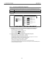
Part Identification and Setting
The part identification and setting method for AJ65BT-64RD is explained below.
2)
MITSUBISHI
MELSEC
AJ65BT-64RD
PW
RUN
L RUN
SD
RD
L ERR.
SW MODE
0 NORMAL
1-4 TEST CH.
9
TEST
1)
B RATE
STATION NO.
• 01
2
•
3
•
• •4
•
•
9)
X10
X1
• 01
901
2
2 8
3
3 7
654
654
MODE OFFSET
UP
SET
901
2
•
•
3
• •4
GAIN
RESET
6)
DOWN
5)
8)
No.
7)
Name
•
•
• 01
2
3
654
901
8
2
7
3
654
Transmission
baud rate
setting switch
Sets the station number of AJ65BT-64RD in the range of 1 to 61.
“ × 10” sets the ten’s place for a station number.
“ × 1” sets the one’s place for a station number.
STATION NO.
10
4)
Description
Station setting
switch
1)
3)
(Factory setting : 00)
1
Sets the transmission speed of AJ65BT-64RD (for data link).
Setting No.
Transmission baud rate
0
156 kbps (factory setting)
B RATE
1
625 kbps
• 01
2
3
• •4
2
2.5 Mbps
3
5 Mbps
2)
•
•
4
10 Mbps
Other than 0 to 4
Unused (if a number other than 0 to 4 is used, the "L ERR. " LED is lit and
communication error occurs.)
Mode switch
0
NORMAL
1 to 4
TEST CH.
9
TEST
MODE
3)
•
•
901
2
3
• •4
Offset/gain
setting switch
4)
OFFSET
During a normal operation, select this to end the test mode.
(Factory setting)
At a test mode, select a channel to perform error compensation.
When executing error compensation, select TEST to enter the test mode after 2 seconds.
OFFSET
Compensation mode of offset value
GAIN
Compensation mode of gain value
SET
Store the detected temperature value when the position is switched from
OFFSET/GAIN to SET as an offset value/gain value, in the internal memory of AJ65BT64RD.
SET
GAIN
4-3
4. SETTING AND PROCEDURE BEFORE OPERATION
No.
Name
UP/DOWN
switch
UP
MELSEC-A
Description
Increase/decrease the offset value/gain value of the channel selected by the mode switch.
ON for less than 1.5 seconds : increase/decrease 0.025 °C at a time.
ON for more than 1.5 seconds : increase/decrease 0.1 °C per 0.04 second.
5)
DOWN
Reset switch
RESET
6)
LED for
operation
status display
Hardware reset
Initialize the remote register of AJ65BT-64RD.
The initial data processing request flag turns on by turning the switch on.
PW
ON : Power is on
OFF : Power is off
ON :
Normal
mode
OFF :
7)
24 V DC power failure or WDT error
Flicker : Flickers when the offset/gain setting switch is set at OFFSET or GAIN
Flickers at 0.5-second intervals when the offset value or gain value being
used for compensation is within the setting range.
Flickers at 0.1-second intervals when the offset value or gain value being
used for compensation is out of the setting range (out of the temperature
input range or the gain value minus the offset value is smaller than +10°C).
In this case, the offset or gain value cannot be memorized.
RUN
PW
RUN
L RUN
SD
RD
L ERR.
Normal operation
Flicker : Read data error occurred
Test mode
OFF :
L RUN
Turns off when the offset/gain setting switch is positioned at SET
ON : Normal communication
OFF : Communication disconnected (time over error)
SD
The light comes on during data transmission
RD
The light comes on during data receiving
ON :
Communication data error (CRC error)
Station number, baud rate switch setting error
Flicker at regular intervals:
Indicates that the station number or baud rate switch setting was
changed while power was on.
L ERR.
Flicker at irregular intervals: Indicates that the terminating resistor is not installed or the module or
CC-Link dedicated cable is affected by noise.
OFF:
Normal communication
AJ65BT-64RD3
1
3
DG
2
4
DB
8)
5
DA
7
+24V
9
24G
6
11
A1
8
10
SLD
(FG)
NC
5
7
9
13
b1
12
B1
15
SLD
14
SLD
17
A2
16
NC
19
b2
18
B2
21
A3
20
NC
23
b3
22
B3
25
SLD
24
SLD
27
A4
b4
26
NC
B4
Terminal block
AJ65BT-64RD4
1
3
DA
DG
2
4
DB
9)
+24V
SLD
24G
6
(FG)
11
A1
8
10
a1
13
b1
B1
15
SLD
12
SLD
17
A2
14
a2
19
b2
16
B2
21
A3
18
a3
23
b3
20
B3
25
SLD
22
SLD
27
A4
24
a4
b4
26
B4
Designates the type of platinum temperature-measuring resistor to be connected to AJ65BT-64RD using a short pin as
either Pt100 (JIS, IEC type) or JPt100 (old JIS type).
Platinum
temperature(Factory setting is Pt100.)
measuring
When connecting Pt100
When connecting JPt100
resistor type
designation pin
Circuit board
4-4
Circuit board
4. SETTING AND PROCEDURE BEFORE OPERATION
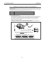
Error Compensation by the Offset Value/Gain Value Setting
The AJ65BT-64RD error compensation is a function that compensates values at arbitrary 2 points
(offset value/gain value) within the usage temperature range at system startup or when a correct
temperature cannot be detected.
The error compensation is executed by reading the detected temperature value in the remote register
using a sequence program and monitoring the values using a peripheral device.
B RATE
SW MODE
0 NORMAL
1-4 TEST CH.
9
TEST
PW
RUN
L RUN
SD
RD
L ERR.
•
•
• 01
2
3
• •4
STATION NO.
•
•
• 01
2
3
654
10
901
8
2
7
3
654
MODE OFFSET
•
•
OFFSET
Lower value of the two
points to be compensated
1
UP
GAIN
GAIN
< Higher value of the two
points to be compensated
(offset value more than +10C°)
RESET
SET
901
2
3
• •4
UP/DOWN adjustment of OFFSET/GAIN
DOWN
The following shows the characteristic of detected temperature value with respect to the input
temperature.
GAIN
80 [°C]
Compensate the detected
temperature value to equal
the input temperature.
79.7
Detected
temperature value
4.4
MELSEC-A
Characteristics before
error compensation
Characteristics after
error compensation
-50 [°C]
0
80 [°C]
Input temperature
-49.7
Compensate the detected
temperature value to equal
the input temperature.
-50 [°C]
OFFSET
•
The error compensation can also be done by using a standard resistor instead of inputting
temperature directly to the platinum temperature-measuring resistor.
Standard resistive value of the platinum temperatureResistive value of standard resistor = measuring resistor against the input temperature to be the
offset value/gain value (Refer to Appendix 1).
4-5
4. SETTING AND PROCEDURE BEFORE OPERATION
MELSEC-A
POINT
• The offset value/gain value can be obtained with a high accuracy when error compensation is
carried out at the minimum and maximum temperatures in the range used.
• Set the offset value/gain value while monitoring the detected temperature value, using a
peripheral device.
• Always set the offset and gain values within the allowable temperature input range so that the
gain value minus offset value is greater than or equal to 10 °C.
If the offset value or gain value being used for compensation is out of the setting range, the
RUN LED fickers at a high speed (at 0.1 second intervals) and the offset or gain value will not
be stored even when the offset/gain setting switch is swiched to SET.
• The offset value and gain value are stored inside AJ65BT-64RD and are not erased even at
power off.
4-6
4. SETTING AND PROCEDURE BEFORE OPERATION
4.4.1
MELSEC-A
Initial settings for error compensation
The following shows the initial settings using a program designed for executing error compensation.
Start
Create a program that designates a sampling
processing and travel average processing *1
Create a program that reads the detected
temperature values
End
*1 Only when executing error compensation with the value detected by travel average processing.
POINT
• Perform the initial settings for error compensation prior to entering the test mode (at normal
mode).
• During the test mode, disable the designation of the conversion enable/disable specification
flag, and enable conversion for the automatically selected channels and disable for the
unselected channels.
4-7
4. SETTING AND PROCEDURE BEFORE OPERATION
4.4.2
MELSEC-A
Error compensation procedure
The following shows the flow of error compensation.
Start
A
Set the mode switch to 9 for test mode.
Check that RUN LED is turned OFF.
RUN
Input a value to be the gain value.
AJ65BT-64RD
MODE
901
•
2
•
3
• • 4
Turns off
after 2
seconds
Or, input standard
resistive value
using a standard
resistor, etc.
Pt100
80 °C
B
Select the channel to compensate using the mode
switch.
Set the offset/gain setting switch at GAIN.
MODE
•
•
901
2
3
• • 4
OFFSET
RUN
Turn the knob
to the channel
to be set.
SET
Flickers at
0.5 second
intervals
GAIN
Input a value to be the offset value.
Adjust the detected temperature value to the gain
value using the UP/DOWN switch.
AJ65BT-64RD
Or, input standard
resistive value
using a standard
resistor, etc.
Pt100
UP
AJ65BT-64RD
797
-50 °C
800
DOWN
Set the offset/gain setting switch at OFFSET.
Set the offset/gain setting switch at SET to memorise
the gain value.
OFFSET
RUN
Flickers at
0.5 second
intervals
SET
GAIN
Off
GAIN
Adjust the detected temperature value to the offset
value using the UP/DOWN switch.
UP
AJ65BT-64RD
-497
OFFSET
RUN
SET
B
NO
Is compensation completed
for the channel used?
500
YES
DOWN
Set the mode switch to 0 and return to the normal
mode.
RUN
Set the offset/gain setting switch at SET to memorise
the offset value.
OFFSET
RUN
MODE
901
•
2
•
3
• •4
Turns on
after 2
seconds
SET
Off
GAIN
End
A
POINT
Once an offset value or gain value is set in the test mode, the set value cannot be confirmed (the
set value is retained in the internal memory.)
4-8
4. SETTING AND PROCEDURE BEFORE OPERATION
4.5
MELSEC-A
Station Number Setting
The buffer memory addresses of the master module, where the remote I/O signals and read/write data
are stored, are determined by the station number setting of the AJ65BT-64RD.
For details, refer to the user's manual (details) of the used master module.
4.6
Orientation of Module Installation
The following shows the possible orientation for AJ65BT-64RD installation.
Panel
When installing alongside the panel
When installing on the panel
4-9
4. SETTING AND PROCEDURE BEFORE OPERATION
4.7
MELSEC-A
Wiring
4.7.1
Wiring example with CC-Link modules
The following shows the connection between the AJ65BT-64RD and master module using CC-Link
dedicated cable.
POINT
For the modules at both ends of the data link, make sure to connect the “terminal resistor” that is
attached to a master module (connect between DA and DB).
4-10
4. SETTING AND PROCEDURE BEFORE OPERATION
4.7.2
MELSEC-A
Precautions when wiring to a platinum temperature-measuring
resistor
To obtain maximum performance from the functions of AJ65BT-64RD and improve the system
reliability, a wiring with high durability against noise is required. The following describes the external
wiring precautions.
(1) Use separate cables for the AC and the external input signals of the AJ65BT-64RD, in order not
to be affected by the AC side surge or conductivity.
(2) Always place a platinum temperature-measuring resistor at least 10 cm (3.9 in.) apart from the
main circuit line and AC control circuit line. Place a platinum temperature-measuring resistor
sufficiently apart from circuits with high frequency, such as high-voltage lines and inverter load
main circuits. If they are placed close to each other, the platinum temperature-measuring
resistor is influenced more easily by the noise, surge, or conductivity.
4.7.3
Connecting AJ65BT-64RD3 and platinum temperature-measuring
resistor
(1) The highest accuracy can be obtained if a 3-wire type platinum temperature-measuring resistor is
used for AJ65BT-64RD3.
The following shows a connection example of a 3-wire type platinum temperature-measuring
resistor.
*1 May be better to connect depending on the operating environment.
(2) A 4-wire type or 2-wire type platinum temperature-measuring resistor can also be used for
AJ65BT-64RD3.
Connect as shown in the diagrams below when using a 4-wire type or 2-wire type platinum
temperature-measuring resistor.
4-wire type
2-wire type
A
A
B
B
b
b
SLD
SLD
4-11
4. SETTING AND PROCEDURE BEFORE OPERATION
4.7.4
MELSEC-A
Connecting AJ65BT-64RD and platinum temperature-measuring
resistor
(1) The highest accuracy can be obtained if a 4-wire type platinum temperature-measuring resistor is
used for AJ65BT-64RD4.
The following shows a connection example of a 4-wire type platinum temperature-measuring
resistor.
*1 May be better to connect depending on the operating environment.
(2) A 4-wire type or 3-wire type platinum temperature-measuring resistor can also be used for
AJ65BT-64RD4.
Connect as shown in the diagrams below when using a 3-wire type or 2-wire type platinum
temperature-measuring resistor.
3-wire type
2-wire type
a
a
A
A
B
B
b
b
SLD
SLD
4-12
5. PROGRAMMING
5.
MELSEC-A
PROGRAMMING
The programming procedure, basic programming for read and write, as well as programming
examples are explained below.
When utilizing the program examples introduced in this chapter for an actual system, fully verify that
controllability in the target system has no problems.
Refer to the user's manual (details) of the used master module for the master module, to Section 3.5
for the remote registers, and to the AnSHCPU/AnACPU/AnUCPU/QCPU-A (A mode) programming
manual (dedicated Instructions) for details of the dedicated instructions.
5.1
Programming Procedure
Create a program that operates the AJ65BT-64RD connected to the master module in the following
procedure:
Start
Select factory setting or user setting for offset/gain values
Initial setting *1
Designate sampling processing/travel average processing
Designate the temperature conversion enable or disable
Read detected temperature value
*2
*2
Processing during error status
• Wire breakage detection
• E2 PROM error
*2
End
*1
When the QCPU (Q mode) is used, initial setting can be made by the remote device station
initialization procedure registration function. When the ACPU, QCPU (A mode) or QnACPU is
used, use a sequence program to make the setting.
*2
Setting cannot be made by the remote device station initialization procedure registration function.
Use a sequence program to make the setting.
5-1
5. PROGRAMMING
5.2
MELSEC-A
Program Example Conditions
The program examples given in this chapter have been created under the following conditions.
(1) System configuration
5-2
5. PROGRAMMING
MELSEC-A
(2) Relationships between programmable controller CPU, master module and AJ65BT-64RD
POINT
Depending on the used CPU module, the devices used in the program examples of this chapter
may not be applicable. For the device setting ranges, refer to the user's manual of the used CPU
module.
For example, when the A1SCPU is used, devices X100, Y100 and later are not applicable. Use
devices such as B and M.
5-3
5. PROGRAMMING
MELSEC-A
(3) Initial setting
Setting item
Description
CH. 1 sampling processing/travel average
processing designation flag (RY04)
CH. 2 sampling processing/travel average
processing designation flag (RY05)
Offset/gain value selection flag (RY77)
Travel average processing
Travel average processing
Factory setting
(4) Other settings
Setting item
Description
CH. 1 conversion enable flag (RY00)
CH. 2 conversion enable flag (RY01)
5-4
Conversion enable
Conversion enable
5. PROGRAMMING
5.3
MELSEC-A
Program Examples when QCPU (Q Mode) Is Used
The network parameters and auto refresh parameters have been set by GX Developer.
Initial setting can be made easily by using the remote device station initialization procedure
registration function.
(1) Parameter setting
(a) Network parameter setting
(b) Auto refresh parameter setting
5-5
5. PROGRAMMING
MELSEC-A
(2) Initial setting by remote device station initialization procedure registration function
(a) Target station number setting
Set the target station number of initial setting.
Set the target station number to "1".
(b) Procedure registration setting
The initial setting is registered to the AJ65BT-64RD when the initial data processing request
flag (RX78) turns ON and Remote device station initialization procedure registration (SB0D) is
set.
The following table indicates the setting results of the initial setting.
Procedure execution condition
Initial data processing request flag (RX78) turns ON
Initial data processing request flag (RX78) turns OFF
Initial data setting completion flag (RX79) turns ON
Execution
CH. 1 sampling processing/travel average processing
designation flag is set to the travel average processing.
(RY04: ON)
CH. 2 sampling processing/travel average processing
designation flag is set to the travel average processing.
(RY05: ON)
Offset/gain value selection flag is set to the factory setting.
(RY77: ON)
Initial data processing completion flag (RY78) is turned ON.
Initial data setting request flag (RY79) is turned ON.
Initial data processing completion flag (RY78) is turned OFF.
Initial data setting request flag (RY79) is turned OFF.
POINT
(1)
When the remote device station initialization procedure registration command (SB000D) is
turned OFF after initial processing, all the RY signals that turned ON in the initial procedure
registration turn OFF. Hence, turn ON the "CH.
conversion enable flag" in a sequence
program.
(2)
When the initial setting (CH.
sampling processing/travel average processing designation
flag, offset/gain selection flag) is changed, the remote device station initialization procedure
registration function cannot be used.
Use a sequence program to change the initial setting.
(c) Setting result
The setting result is shown below.
5-6
5. PROGRAMMING
MELSEC-A
(3) Program example
5-7
5. PROGRAMMING
MELSEC-A
*1: When making remote device station initialization procedure registration to multiple stations, correct
the program within the dotted line 1) as shown below.
[System configuration]
[Corrected program]
• RX(m+7)9 and RX(n+7)9 are initial data setting completion flags.
• RX(m+7)8 and RX(n+7)8 are initial data processing request flags.
Insert the remote READY and initial data processing request flags for all the stations, to which
the remote device station initialization procedure registration has been made, into the
program.
5-8
5. PROGRAMMING
MELSEC-A
[Usage in combination with other remote device stations]
(1) Depending on the remote device stations to be used, the program enclosed by the dotted line 1)
has two programming patterns as shown in the above and the below figures.
(To check which pattern can be used, refer to the manual for the remote device to be used.)
[System configuration]
Master station
Remote device
station3
Remote device
station4
RX(p+1)B
RX(p+1)8
RX(q+1)B
RX(q+1)8
[Corrected program]
• RX(p+1)B and RX(q+1)B are remote READY.
• RX(p+1)8 and RX(q+1)8 are initial data processing request flags.
5-9
5. PROGRAMMING
MELSEC-A
(2) When using the program enclosed by the dotted line 1) in combination with other remote device
stations, correct the program as shown below.
[System configuration]
[Corrected program]
Note that the master module can register the initialization procedure of only the specified
station out of the multiple remote device stations.
The master module supporting this function is the QJ61BT11N which serial No's first 5 digits is
08032 or later.
Fro details, refer to the CC-Link System Master/Local Module User's Manual, "CHAPTER 4
FUNCTIONS"
*2: Before the communication program is executed with remote device stations, the program enclosed
by the dotted line 1) enables the initial setting by using the SB0D (remote device station
initialization procedure registration instruction) and SB5F (completion status of remote device
station initialization procedure). Initialization processing can't be made only by the parameter
setting of GX Developer.
*3: The program enclosed by the dotted line 2) is necessary only when the initial settings are changed.
5-10
5. PROGRAMMING
5.4
MELSEC-A
Program Examples when QnACPU Is Used
The network parameters and auto refresh parameters have been set by GX Developer.
(1) Parameter setting
(a) Network parameter setting
(b) Auto refresh parameter setting
5-11
5. PROGRAMMING
MELSEC-A
(3) Program example
AJ65BT-64RD status check
Reads data link status.
AJ65BT-64RD
data link normal
AJ65BT-64RD
data link abnormal
Initial setting
CH. 1 sampling processing/
travel average processing
designation flag (RY04)
CH. 2 sampling processing
/travel average processing
designation flag (RY05)
Offset/gain value
selection flag (RY77)
Turns ON initial data
processing completion
flag (RY78).
Turns OFF initial data
processing completion
flag (RY78).
Initial setting change
Initial setting change
CH. 1 sampling processing/
travel average processing
designation flag (RY04)
CH. 2 sampling processing
/travel average processing
designation flag (RY05)
Offset/gain value
selection flag (RY77)
Turns ON initial data setting
request flag (RY79).
Turns OFF initial data setting
request flag (RY79).
Conversion enable/disable designation
CH.
1 conversion enable
CH. 1変変許許
Turns ON CH. 1 conversion
enable flag (RY00).
CH.
2 conversion enable
CH. 2変変許許
Turns ON CH. 2 conversion
enable flag (RY01).
Detected temperature value read
Reads CH. 1 detected
temperature value (16 bits)
(RWr0).
Reads CH. 1 detected
temperature value (32 bits)
(RWr4, RWr5).
Reads CH. 2 detected
temperature value (16 bits)
(RWr1).
Reads CH. 2 detected
temperature value (32 bits)
(RWr6, RWr7).
Handling at error occurrence
Turns ON Y91 when E2PROM
is faulty.
Turns ON Y92 when CH. 1
wire breakage is detected.
Turns ON Y93 when CH. 2
wire breakage is detected.
Error reset
Turns ON error reset
request flag (RY7A).
Turns OFF error reset
request flag (RY7A).
*The program within the dotted frame is necessary only when the initial setting is changed.
5-12
5. PROGRAMMING
5.5
MELSEC-A
Program Example when ACPU/QCPU (A Mode) Is Used
(Dedicated Instructions)
The network parameters and auto refresh parameters have been set by the sequence program.
(1) Program example
Network parameter setting by dedicated instruction RLPA
Synchronous mode invalid
Number of connected
modules: 1
AJ65BT-64RD station
information
(remote device station, 4
stations occupied, station
No. 1)
Dedicated instruction
(RLPA)
Master module head
I/O No.
Parameter storage
head device
Device that turns ON
1 scan at completion
Reads parameter status
at abnormal completion.
Auto refresh parameter setting by dedicated instruction RRPA check
RX head number setting
"X" setting
X400 setting
128 points setting
RY head number setting
"Y" setting
Y400 setting
128 points setting
RW head number setting
"D" setting
D200 setting
263 points setting
5-13
5. PROGRAMMING
MELSEC-A
SB head number setting
"B" setting
B0 setting
512 points setting
SW head number setting
"W" setting
W0 setting
256 points setting
Dedicated instruction (RRPA)
Master module head I/O No.
Parameter storage head
device
AJ65BT-64RD status check
Reads data link status.
AJ65BT-64RD
data link normal
AJ65BT-64RD
data link abnormal
Initial setting
CH. 1 sampling processing/
travel average processing
designation flag (RY04)
CH. 2 sampling processing
/travel average processing
designation flag (RY05)
Offset/gain value
selection flag (RY77)
Turns ON initial data
processing completion
flag (RY78).
Turns OFF initial data
processing completion
flag (RY78).
Initial setting change
イ
イ イ setting
イ イ 設設変変
Initial
change
CH. 1 sampling processing/
travel average processing
designation flag (RY04)
CH. 2 sampling processing
/travel average processing
designation flag (RY05)
Offset/gain value
selection flag (RY77)
Turns ON initial data
setting request flag (RY79).
Turns OFF initial data
setting request flag (RY79).
* The program within the dotted frame is necessary only when the initial setting is changed.
5-14
5. PROGRAMMING
MELSEC-A
Conversion enable/disable designation
CH. 1 conversion enable
Turns ON CH. 1 conversion
enable flag (RY00).
CH.
2 conversion enable
CH. 2変変許許
Turns ON CH. 2 conversion
enable flag (RY01).
Detected temperature value read
Reads CH. 1 detected
temperature value (16 bits)
(RWr0).
Reads CH. 1 detected
temperature value (32 bits)
(RWr4, RWr5).
Reads CH. 2 detected
temperature value (16 bits)
(RWr1).
Reads CH. 2 detected
temperature value (32 bits)
(RWr6, RWr7).
Handling at error occurrence
Turns ON Y91 when E2PROM
is faulty.
Turns ON Y92 when CH. 1
wire breakage is detected.
Turns ON Y93 when CH. 2
wire breakage is detected.
Error reset
Turns ON error reset
request flag (RY7A).
Turns OFF error reset
request flag (RY7A).
5-15
5. PROGRAMMING
5.6
MELSEC-A
Program Example when ACPU/QCPU (A Mode) Is Used (FROM/TO
Instructions)
The network parameters have been set by the sequence program.
(1) Program example
5-16
5. PROGRAMMING
MELSEC-A
Initial setting
CH. 1 sampling processing/
travel average processing
designation flag (RY04)
CH. 2 sampling processing
/travel average processing
designation flag (RY05)
Offset/gain value
selection flag (RY77)
Turns ON initial data
processing completion
flag (RY78).
Turns OFF initial data
processing completion
flag (RY78).
Initial setting change
イ イ イsetting
イ イ 設設変変
Initial
change
CH. 1 sampling processing/
travel average processing
designation flag (RY04)
CH. 2 sampling processing
/travel average processing
designation flag (RY05)
Offset/gain value
selection flag (RY77)
Turns ON initial data setting
request flag (RY79).
Turns OFF initial data setting
request flag (RY79).
Conversion enable/disable designation
CH.
1 conversion enable
CH. 1変変許許
Turns ON CH. 1 conversion
enable flag (RY00).
CH.
2 conversion enable
CH. 2変変許許
Turns ON CH. 2 conversion
enable flag (RY01).
Detected temperature value read
Reads CH. 1 detected
temperature value (16 bits)
(RWr0).
Reads CH. 1 detected
temperature value (32 bits)
(RWr4, RWr5).
Reads CH. 2 detected
temperature value (16 bits)
(RWr1).
Reads CH. 2 detected
temperature value (32 bits)
(RWr6, RWr7).
Handling at error occurrence
Turns ON Y91 when E2PROM
is faulty.
Turns ON Y92 when CH. 1
wire breakage is detected.
Turns ON Y93 when CH. 2
wire breakage is detected.
Error
エ エ エreset
リ リリ リ
Turns ON error reset
request flag (RY7A).
Turns OFF error reset
request flag (RY7A).
Remote output signal write
Writes RY00-RY7F data to
Y400-Y47F.
*The program within the dotted frame is necessary only when the initial setting is changed.
5-17
6. TROUBLESHOOTING
6.
MELSEC-A
TROUBLESHOOTING
The general troubleshooting methods for using AJ65BT-64RD is explained below.
6.1
Cause of Errors and Corrective Actions by LED Indication
The following describes the error confirmation method using the LEDs on AJ65BT-64RD.
For the errors associated with the programmable controller CPU and master module, refer to the
user’s manual for the programmable controller CPU and master module, respectively.
(1) When AJ65BT-64RD’s “RUN” LED is off
Cause
Corrective action
Confirm the watchdog timer error with the master module’s
special link register, then restart the power to AJ65BT-64RD *1.
Watchdog timer error occurred.
If “RUN” LED does not come on after power restart, contact the
nearest representative or branch regarding the problem, as
hardware may be faulty.
24 V DC power is not supplied to AJ65BT-64RD,
Check the voltage of 24 V DC power supply.
or voltage is insufficient.
At test mode, the offset/gain setting switch is
positioned at SET.
After setting offset/gain, position the mode switch to 0
(NORMAL).
(2) When AJ65BT-64RD’s “RUN” LED flikers at 0.5-second intrvals
Cause
Corrective action
At test mode, the offset/gain setting switch is
positioned at OFFSET or GAIN.
After setting offset/gain, position the mode switch to 0
(NORMAL).
(3) When AJ65BT-64RD’s “RUN” LED flikers at 0.1-second intrvals
Cause
Corrective action
In the test mode the offset or gain value being
Set the offset value or gain value within the following range :
used for compensation has exceeded the setting • Within the temperature input range
range.
• (Gain value) – (Offset value) ≥ 10 °C
6-1
6. TROUBLESHOOTING
MELSEC-A
(4) When AJ65BT-64RD’s “L RUN.” LED is off
Cause
Corrective action
Look for the broken or shorted transmission cables and repair
them.
Cables are broken or shorted.
The master station has the stopped data link.
Confirm that no error has occurred in the master station.
Duplicate station number.
Correct the station number setting of the duplicate module, then
restart the power *1.
The setting switch is set outside the range
(station number 0, or 62 or greater, transmission Correct the setting switch setting, then restart the power *1.
speed 5 to 9).
(5) When AJ65BT-64RD’s “L ERR.” LED flikers
Cause
Corrective action
The setting of station number switch or
transmission speed switch is changed during
normal operation.
The station number switch or transmission
speed switch is faulty.
Reinstate the station number or transmission speed setting to
the original setting before the change, then restart the power.
*1.
If “L RUN” LED does not come on after power restart, contact
the nearest representative or branch regarding the problem, as
hardware may be faulty.
If “L ERR.” LED starts to flicker while in operation even though
no change has been made to the switch setting, contact the
nearest representative or branch regarding the problem, as
hardware may be faulty.
(6) When AJ65BT-64RD’s “L ERR.” LED is on
Cause
Corrective action
The setting switch is set outside the range
(station number 0, or 62 or greater, transmission Correct the setting switch setting, then restart the power. *1
speed 5 to 9).
Confirm whether the terminal resistor is installed. If the terminal
resistor is not connected, connect it, then restart the power. *1
Forgot to install the terminal resistor.
AJ65BT-64RD or transmission cable is affected
by noise.
• Ground (class D grounding) the both ends of shield of the
CC-Link dedicated cable via SLD and FG of each module.
• Securely ground the FG terminal of the module.
• When performing pipe wiring, securely ground the pipe.
*1 Restart power : Turn on the power supply again, or turn on the reset switch.
6-2
6. TROUBLESHOOTING
6.2
MELSEC-A
When Wire Breakage Detection Flag is On
Cause
6.3
Corrective action
Connection between platinum temperaturemeasuring resistor and cable is incomplete.
Securely connect the platinum temperature-measuring resistor
and cable.
Terminal screw is loose.
Tighten the terminal screws within the specified torque range.
The connected platinum temperature-measuring
resistor or cable has wire breakage.
Check the continuity of platinum temperature-measuring
resistor and cable, and replace the broken platinum
temperature-measuring resistor or cable.
The channel to which platinum temperaturemeasuring resistor is not connected is
designated as conversion enabled.
Confirm the channels for which the conversion enable is
designated and channel to which platinum temperaturemeasuring resistor is connected, then correct the conversion
enable designation.
When E2PROM Error Flag is On
Cause
Corrective action
Restart power for AJ65BT-64RD. *1
Error in the internal memory storing the offset
value/gain value set by user
If the E2PROM error flag is still on after power restart, contact
the nearest representative or branch regarding the problem, as
hardware may be faulty.
*1 Restart power : Turn on the power supply again, or turn on the reset switch.
6.4
When Detected Temperature Value cannot be Read
Cause
6.5
Corrective action
The channel used is designated as conversion
disabled.
Designate the channel as conversion enable in sequence
program.
Programmable controller CPU or master module
error
Confirm the programmable controller CPU and master module.
When Detected Temperature Value is Abnormal
Cause
Corrective action
The platinum temperature-measuring resistor
connected is different from what is designated.
Designate the platinum temperature-measuring resistor
connected.
Affected by noise.
Confirm the influence from grounding and adjacent devices,
then take measures against noise.
6-3
6. TROUBLESHOOTING
6.6
MELSEC-A
When There is a Communication Error between Master Station
and AJ65BT-64RD
If the station number duplicate bit is turned on in the link special register SW0098 to SW009B
(duplicate station number status), check the corresponding station number of AJ65BT-64RD using the
following flow.
Troubleshooting flow when “ERR.” LED of master station is flickering
" ERR." LED of master
station flickers
Do the
parameter setting
and loading system
configuration
match?
Y
N
Correct parameter setting or
loading system configuration
Is the
master station
link special register
SW0080 to SW0083 (other
station data link
status) turned
ON?
Y
Is the
master station
link special register
SW0098 to SW009B
(duplicate station
number status)
turned ON?
N
Master station failure
N
Y
Check the module whose
SW0098 to SW009B is ON
Is the station
number switch set
correctly?
Y
Check on the master side
Check the module whose
SW0080 to SW0083 is ON
N
Is power supply
turned ON?
Set the station number
switch correctly
N
Turn the power ON
Y
Is " POWER"
LED lit?
Restart the power supply/
Turn on the reset switch
Check on the AJ65BT-64RD side
N
Y
Is the supplied
voltage within the
specified range?
Corresponding module failure
Y
N
Set the supplied voltage
within the specified range
Corresponding module failure
Is " RD" LED lit?
N
Are
communication
cables connected
correctly?
*1
Y
Y
N
Correct the wiring of
communication cables
Corresponding module failure
To the next page
To the next page
6-4
To the next page
6. TROUBLESHOOTING
From the previous page
MELSEC-A
From the previous page
From the previous page
N
Is "L RUN" LED lit?
Y
N
Is "SD" LED lit
(flickering)?
Y
Is "SD" LED lit
(flickering)?
N
Is the baud rate
setting correct?
N
Y
Correct the baud rate setting
Y
Corresponding
module failure
Restart the power supply/
Turn ON the reset switch
Are the
communication
cables connected
correctly?
*1
Y
N
Connect the communication
cables correctly
Corresponding module failure
(baud rate switch)
Is the
station number
switch set correctly (not
duplicated with other
station)?
N
Set the station number correctly
Y
Restart the power supply/
Turn ON the reset switch
Corresponding module failure
(station number switch)
Is the
station number
switch set correctly (not
duplicated with other
station)?
Y
N
Set the station number correctly
Restart the power supply/
Turn ON the reset switch
Corresponding module failure
(station number switch)
Complete
*1 Check for short-circuits, reversed connection, wire breakage, terminal resistor, FG connection,
overall distance and station-to-station distance.
6-5
APPENDIX
MELSEC-A
APPENDIX
Appendix 1 Standard Thermal Electromotive Force of Platinum
Temperature-Measuring Resistor
Appendix 1.1
New JIS⋅IEC type (Pt100)
JIS C 1604-1997,
Tempe
rature
[°C]
Tempe
rature
[°C]
Unit : Ω
IEC 751-1983
–100
–0
60.26
100.00
–0
0
100.00
138.51
175.86
212.05
56.19
96.09
–10
10
103.90
142.29
179.53
215.61
52.11
92.16
–20
20
107.79
146.07
183.19
219.15
253.96
287.62
48.00
88.22
–30
30
111.67
149.83
186.84
222.68
257.38
290.92
43.88
84.27
–40
40
115.54
153.58
190.47
226.21
260.78
294.21
39.72
80.31
–50
50
119.40
157.33
194.10
229.72
264.18
297.49
35.54
76.33
–60
60
123.24
161.05
197.71
233.21
267.56
300.75
31.34
72.33
–70
70
127.08
164.77
201.31
236.70
270.93
304.01
27.10
68.33
–80
80
130.90
168.48
204.90
240.18
274.29
307.25
64.30
–90
90
134.71
172.17
208.48
243.64
277.64
310.49
Appendix 1.2
0
100
200
300
400
500
600
247.09
280.98
313.71
250.53
284.30
Old JIS type (JPt100)
Unit : Ω
JIS C 1604-1981
–100
–0
Tempe
rature
[°C]
Tempe
rature
[°C]
0
100
200
300
400
500
600
59.57
100.00
–0
0
100.00
139.16
177.13
213.30
249.56
284.02
317.28
55.44
96.02
–10
10
103.97
143.01
180.86
217.54
253.06
287.40
51.29
92.02
–20
20
107.93
146.85
184.58
221.15
256.55
290.77
47.11
88.01
–30
30
111.88
150.67
188.29
224.74
260.02
294.12
42.91
83.99
–40
40
115.81
154.49
191.99
228.32
263.49
297.47
38.68
79.96
–50
50
119.73
158.29
195.67
231.89
266.94
300.80
34.42
75.91
–60
60
123.64
162.08
199.35
235.45
270.38
304.12
30.12
71.85
–70
70
127.54
165.86
203.01
238.99
273.80
307.43
25.80
67.77
–80
80
131.42
169.63
206.66
242.53
277.22
310.72
63.68
–90
90
135.30
173.38
210.30
246.05
280.63
314.01
A-1
APPENDIX
MELSEC-A
Appendix 2 External Dimensions Diagram
(1) AJ65BT–64RD3
(2) AJ65BT–64RD4
A-2
WARRANTY
Please confirm the following product warranty details before using this product.
1. Gratis Warranty Term and Gratis Warranty Range
If any faults or defects (hereinafter "Failure") found to be the responsibility of Mitsubishi occurs during use of the product
within the gratis warranty term, the product shall be repaired at no cost via the sales representative or Mitsubishi Service
Company.
However, if repairs are required onsite at domestic or overseas location, expenses to send an engineer will be solely at
the customer’s discretion. Mitsubishi shall not be held responsible for any re-commissioning, maintenance, or testing onsite that involves replacement of the failed module.
[Gratis Warranty Term]
The gratis warranty term of the product shall be for one year after the date of purchase or delivery to a designated
place.
Note that after manufacture and shipment from Mitsubishi, the maximum distribution period shall be six (6) months, and
the longest gratis warranty term after manufacturing shall be eighteen (18) months. The gratis warranty term of repair
parts shall not exceed the gratis warranty term before repairs.
[Gratis Warranty Range]
(1) The range shall be limited to normal use within the usage state, usage methods and usage environment, etc.,
which follow the conditions and precautions, etc., given in the instruction manual, user's manual and caution labels
on the product.
(2) Even within the gratis warranty term, repairs shall be charged for in the following cases.
1. Failure occurring from inappropriate storage or handling, carelessness or negligence by the user. Failure caused
by the user's hardware or software design.
2. Failure caused by unapproved modifications, etc., to the product by the user.
3. When the Mitsubishi product is assembled into a user's device, Failure that could have been avoided if functions
or structures, judged as necessary in the legal safety measures the user's device is subject to or as necessary
by industry standards, had been provided.
4. Failure that could have been avoided if consumable parts (battery, backlight, fuse, etc.) designated in the
instruction manual had been correctly serviced or replaced.
5. Failure caused by external irresistible forces such as fires or abnormal voltages, and Failure caused by force
majeure such as earthquakes, lightning, wind and water damage.
6. Failure caused by reasons unpredictable by scientific technology standards at time of shipment from Mitsubishi.
7. Any other failure found not to be the responsibility of Mitsubishi or that admitted not to be so by the user.
2. Onerous repair term after discontinuation of production
(1) Mitsubishi shall accept onerous product repairs for seven (7) years after production of the product is discontinued.
Discontinuation of production shall be notified with Mitsubishi Technical Bulletins, etc.
(2) Product supply (including repair parts) is not available after production is discontinued.
3. Overseas service
Overseas, repairs shall be accepted by Mitsubishi's local overseas FA Center. Note that the repair conditions at each FA Center may
differ.
4. Exclusion of loss in opportunity and secondary loss from warranty liability
Regardless of the gratis warranty term, Mitsubishi shall not be liable for compensation of damages caused by any cause
found not to be the responsibility of Mitsubishi, loss in opportunity, lost profits incurred to the user by Failures of Mitsubishi
products, special damages and secondary damages whether foreseeable or not , compensation for accidents, and
compensation for damages to products other than Mitsubishi products, replacement by the user, maintenance of on-site
equipment, start-up test run and other tasks.
5. Changes in product specifications
The specifications given in the catalogs, manuals or technical documents are subject to change without prior notice.
SH(NA)-4001-E
SH(NA)-4001-E(1012)MEE
MODEL:
AJ65BT-64RD-U-E
MODEL CODE: 13JL54
HEAD OFFICE : TOKYO BUILDING, 2-7-3 MARUNOUCHI, CHIYODA-KU, TOKYO 100-8310, JAPAN
NAGOYA WORKS : 1-14 , YADA-MINAMI 5-CHOME , HIGASHI-KU, NAGOYA , JAPAN
When exported from Japan, this manual does not require application to the
Ministry of Economy, Trade and Industry for service transaction permission.
Specifications subject to change without notice.