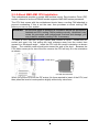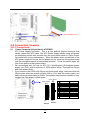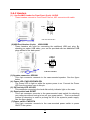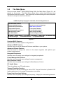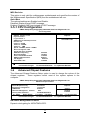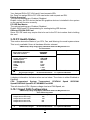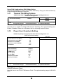
1
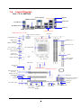
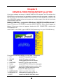
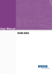
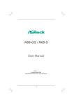
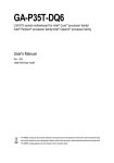
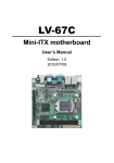
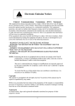
USER'S MANUAL
Of
AMD 785G & AMD SB710
Based
M/B For Socket AM3 Series Quad Core
Processor
NO. G03-MA3785GP-F
Rev:1.0
Release date: Aug., 2009
Trademark:
* Specifications and information contained in this documentation are furnished for information use only, and are
subject to change at any time without notice, and should not be construed as a commitment by manufacturer.
Environmental Protection Announcement
Do not dispose this electronic device into the trash while discarding. To minimize pollution
and ensure environment protection of mother earth, please recycle.
ii
TABLE OF CONTENT
USER’S NOTICE .........................................................................................................iii
MANUAL REVISION INFORMATION .........................................................................iii
COOLING SOLUTIONS ..............................................................................................iii
CHAPTER 1 INTRODUCTION OF AMD 785G MOTHERBOARDS
1-1
1-2
1-3
1-4
FEATURES OF MOTHERBOARD ............................................................................. 1
1-1.1 SPECIAL FEATURES OF MOTHERBOARD ............................................... 2
SPECIFICATION ......................................................................................................... 3
PERFORMANCE LIST................................................................................................ 4
LAYOUT DIAGRAM.................................................................................................... 5
CHAPTER 2
2-1
2-2
2-3
2-4
2-5
2-6
2-7
HARDWARE INSTALLATION
HARDWARE INSTALLATION STEPS ....................................................................... 7
CHECKING MOTHERBOARD'S JUMPER SETTING................................................ 7
INSTALL CPU ............................................................................................................. 8
2-3-1 GLOSSARY................................................................................................... 8
2-3-2 ABOUT AMD AM3 INSTALLATION .......................................................... 9
INSTALL MEMORY .................................................................................................... 10
EXPANSION CARDS.................................................................................................. 11
2-5-1 PROCEDURE FOR EXPANSION CARD INSTALLATION .......................... 11
2-5-2 ASSIGNING IRQS FOR EXPANSION CARD .............................................. 11
2-5-3 PCI-EXPRESS SLOT ...................................................................................... 11
CONNECTORS, HEADERS ...................................................................................... 12
2-6-1 CONNECTORS ............................................................................................. 12
2-6-2 HEADERS ..................................................................................................... 15
STARTING UP YOUR COMPUTER ........................................................................... 18
CHAPTER 3
INTRODUCING BIOS
3-1
3-2
3-3
3-4
3-5
ENTERING SETUP ..................................................................................................... 19
GETTING HELP .......................................................................................................... 19
THE MAIN MENU........................................................................................................ 20
STANDARD BIOS FEATURES .................................................................................. 21
ADVANCED BIOS FEATURES .................................................................................. 22
3-5-1 CPU CONFIGURATION ............................................................................. 23
3-6 ADVANCED CHIPSET FEATURES ........................................................................... 23
3-6-1 MEMORYCONFIGURATION ..................................................................... 24
3-6-2 INTERNAL GRAPHICES CONFIGURATION ............................................ 25
3-6-3 PCI EXPRESS CONFIGURATION ............................................................ 25
3-7 INTEGRATED PERIPHERALS................................................................................... 26
3-7-1
ONBOARD SATA DEVICE.......................................................................... 26
3-7-2
ONCHIP DEVICE CONTROL ...................................................................... 26
3-7-3
SUPER IO CONFIGURATION ..................................................................... 27
3-8 POWER MANAGEMENT SETUP............................................................................... 27
3-9 MISCELLANEOUS CONTROL ................................................................................. 28
3-10 PC HEALTH STATUS.................................................................................................. 29
3-10-1 SMART FAN CONFIGURATION .................................................................. 29
3-11 THERMAL THROTTLING OPTIONS........................................................................... 30
3-12 POWER USER OVERCLOCK SETTING .................................................................. 30
3-13 BIOS SECURITY FEATURES................................................................................... 31
3-14 LOAD OPTIMISED DEFAULTS /LOAD STANDARD DEFAULTS .......................... 31
3-15 SAVE CHAGES AND EXIT/DIACARD CHANGES AND EXIT ................................ 32
CHAPTER 4
DRIVER & FREE PROGRAM INSTALLATION
MAGIC INSTALL SUPPORTS WINDOWS 2000/XP/VISTA/WINDOES7........................... 33
4-1 ATI INSTALL ATI DRIVER PACK ....................................................................... 34
4-2 SOUND INSTALL HD CODEC AUDIO DRIVER ................................................... 35
4-3 LAN INSTALL GIGABIT ETHERNET NIC DRIVER................................................. 36
4-4 RAID INSTALL ATI SATA DRIVER AND UTILITY .................................................... 36
4-5 NORTON INSTALL NORTON 2009ANTI-VIRUS PROGRAM................................... 37
4-6 PC-HEALTH INSTALL MYGUARD HARDWARE MONITOR UTILITY .................. 37
4-7 PC-HEALTH INSTALL MYGUARD HARDWARE MONITOR UTILITY .................. 37
4-8 HDMI INSTALLATI HDMI AUDIO DRIVER ............................................................. 38
ii
4-9 OVERCLOCK INSTALL OVER CLOCK DRIVER UTILITY ....................................... 38
4-10 HOW TO UPDATE BIOS ............................................................................................ 40
4-11 AMD PLATFORM RAID FUNCTION INSTALLATION .............................................. 40
4-12 G.P.I FUNCTION LED DISPLAY ................................................................................ 44
APPENDIX I.......................................................................................................................... 45
Safety Environmental Instruction
z
Avoid the dusty, humidity and temperature extremes. Do not place the product in
any area where it may become wet.
z
0 to 40 centigrade is the suitable temperature. (The figure comes from the request
of the main chipset)
z
Generally speaking, dramatic changes in temperature may lead to contact
malfunction and crackles due to constant thermal expansion and contraction from
the welding spots’ that connect components and PCB. Computer should go
through an adaptive phase before it boots when it is moved from a cold
environment to a warmer one to avoid condensation phenomenon. These water
drops attached on PCB or the surface of the components can bring about
phenomena as minor as computer instability resulted from corrosion and oxidation
from components and PCB or as major as short circuit that can burn the
components. Suggest starting the computer until the temperature goes up.
z
The increasing temperature of the capacitor may decrease the life of computer.
Using the close case may decrease the life of other device because the higher
temperature in the inner of the case.
z
Attention to the heat sink when you over-clocking. The higher temperature may
decrease the life of the device and burned the capacitor.
iii
USER’S NOTICE
COPYRIGHT OF THIS MANUAL BELONGS TO THE MANUFACTURER. NO PART OF
THIS MANUAL, INCLUDING THE PRODUCTS AND SOFTWARE DESCRIBED IN IT MAY
BE REPRODUCED, TRANSMITTED OR TRANSLATED INTO ANY LANGUAGE IN ANY
FORM OR BY ANY MEANS WITHOUT WRITTEN PERMISSION OF THE
MANUFACTURER.
THIS MANUAL CONTAINS ALL INFORMATION REQUIRED TO USE THIS
MOTHERBOARD AND WE DO ASSURE THIS MANUAL MEETS USER’S REQUIREMENT
BUT WILL CHANGE, CORRECT ANY TIME WITHOUT NOTICE. MANUFACTURER
PROVIDES THIS MANUAL “AS IS” WITHOUT WARRANTY OF ANY KIND, AND WILL NOT
BE LIABLE FOR ANY INDIRECT, SPECIAL, INCIDENTIAL OR CONSEQUENTIAL
DAMAGES (INCLUDING DAMANGES FOR LOSS OF PROFIT, LOSS OF BUSINESS, LOSS
OF USE OF DATA, INTERRUPTION OF BUSINESS AND THE LIKE).
PRODUCTS AND CORPORATE NAMES APPEARING IN THIS MANUAL MAY OR MAY
NOT BE REGISTERED TRADEMARKS OR COPYRIGHTS OF THEIR RESPECTIVE
COMPANIES, AND THEY ARE USED ONLY FOR IDENTIFICATION OR EXPLANATION
AND TO THE OWNER’S BENEFIT, WITHOUT INTENT TO INFRINGE.
Manual Revision Information
Reversion
1.0
Revision History
First Edition
Date
Aug., 2009
Item Checklist
5
5
5
5
5
AMD785G Platform Processor Chipset based motherboard
CD for motherboard utilities
User’s Manual
SATA Cable
I/O back panel
AMD AM3 Processor Family
Cooling Solutions
As processor technology pushes to faster speeds and higher performance with increasing
operation clock, thermal management becomes increasingly crucial while building computer
systems. Maintaining the proper computing environment without thermal increasing is the key to
reliable, stable, and 24 hours system operation. The overall goal is keeping the processor
below its specified maximum case temperature. Heatsinks induce improved processor heat
dissipation through increasing surface area and concentrated airflow from attached active
cooling fans. In addition, interface materials allow effective transfers of heat from the
processor to the heatsink. For optimum heat transfer, AMD recommends the use of thermal
grease and mounting clips to attach the heatsink to the processor.
Please refer to the website below for collection of heatsinks evaluated and recommended for
Socket AM3 processors by AMD. In addition, this collection is not intended to be a
comprehensive listing of all heatsinks that support AM3 processors.
iv
Chapter 1
Introduction of AMD785G Motherboards
1-1
Features of motherboard
The AMD785G chipset motherboard series are based on the latest AMD785G Chipset
and the SB710 chipset which supports the innovative AMD Phenom™ II X3 processor
and AMD Phenom™ II X 4 processors. With an integrated low-latency high-bandwidth
DDRIII memory controller and a highly-scalable Hyper Transport technology-based
system bus up to HT 3.0. AMD785G Platform Processor Chipset motherboard series
deliver the outstanding system performance and professional desktop platform
solution.
The AMD785G Series motherboards support new generation Socket AM3 processors
with an integrated DDRIII memory controller for Dual channel DDRIII800 /DDRIII1066/
DDRIII1333/DDRIII1600 DDRIII Module up to 8GB, also provide a DDRIII 128Mb
GPU Memory. The motherboard is embedded with SB710 chipset of providing ULTRA
ATA 133 connectors and Serial ATA2 with RAID 0, 1, 10 functions which support up to
one IDE and six Serial ATA2 devices to accelerate hard disk drives and guarantee the
data security without failure in advanced computing performance.
The AMD785G motherboards provide PCI-E Gigabit LAN chip which supports
10/100/1000Mbps data transfer rate. And the embedded ALC662 6-channel HD Audio
CODEC is fully compatible with Sound Blaster Pro standards that offer you with the
home cinema quality and satisfying software compatibility.
AMD785G Series motherboard series offer one PCI-Express2.0x16 graphics slots.
One PCI-Express 2.0 x16by16 deliver up to 8Gbyte/sec data transfer rate at each
relative direction. The AMD785G motherboards also carry two 32-bit PCI slots
guarantee the rich connectivity for the I/O peripheral devices. This motherboard
support Hybrid CrossFire function: when this function is selected through BIOS setting,
the VGA Card on PE1 and the integrated graphics chip together will activate a Hybrid
CrossFire with and the performance will be increased 15% to 75%.
Embedded USB controllers as well as capability of expanding to 8 of USB2.0
functional ports delivering 480Mb/s bandwidth of rich connectivity, these
motherboards meet the future USB demands which are also equipped with hardware
monitor function on system to monitor and protect your system and maintain your
non-stop business computing.
Some special features--- CPU Thermal Throttling/ CPU VID/OC-CON/ G.P.I Function/3D
Audio/Windows7in this motherboard are designed for power user to use the
over-clocking function in more flexible ways. But please be caution that the
over-clocking maybe causes the fails in system reliabilities. This motherboard
provides the guaranteed performance and meets the demands of the next generation
computing. But if you insist to gain more system performance with variety possibilities
1
of the components you choose, please be careful and make sure to read the detailed
descriptions of these value added product features, please get them in the coming
section.
1-1.1
Special Features of Motherboard
CPU Thermal Throttling Technology---(The CPU Overheat Protection Technology)
To prevent the increasing heat from damage of CPU or accidental shutdown while at high
workload, the CPU Thermal Throttling Technology will force CPU to enter partially idle mode from
87.5% to 12.5% according to preset CPU operating temperature in BIOS (from 40℃ to 90℃).
When the system senses the CPU operating temperature reaching the preset value, the CPU
operating bandwidth will be decreased to the preset idle percentage to cool down the processor.
When at throttling mode the beeper sound can be optionally selected to indicate it is in working.
(For detail operating please read Section 3-11 Bi-turbo Configuration)
CPU VID--- (Shift to Higher Performance)
The CPU voltage can be adjusted for the precisely over-clocking of extra demanding computing
performance.
OC-CON ---(High-polymer Solid Electrolysis Aluminum Capacitors)
The working temperature is from 55 degrees Centigrade below zero to 125 degrees Centigrade,
OC-CON capacitors possess superior physical characteristics that can be while reducing the
working temperature between 20 degrees Centigrade each time, intact extension 10 times of
effective product operation lives, at not rising degrees Centigrade of working temperatures each
time a relative one, life of product decline 10% only too.
G.P.I Function--- G.P.I is a technology with remarkable power saving function: when you are
using a computer with G.P.I mold turned on, you save averagely 10.5W in power consumption in
the whole process than normal computer without G.P.I technology.
3D Audio
OP with two-stage Butterworth filter and quadruple noninverting amplifier enhances bass effect
under the 100MHz range to perfect audio effect, brings you stunning shock experience in video
game, true-to-life simulated feeling when watching films and the greatest touch as that in the
concert.
2
1-2
Specification
Spec
Design
Chipset
CPU Socket AM2
Description
z
Micro ATX form factor; 4 layers PCB ;size:24.5cm*21.0cm
z
z
z
AMD785G North Bridge Chipset
AMD SB710 South Bridge Chipset
Support AMD AM3 processors: AMD Phenom™ II X3 and AMD
Phenom™ II X4 processors
Support HT 3.0
z
Memory Socket
GPU Memory
Expansion Slot
z
z
z
z
240-pin DDRIII Module socket x 2
Support 2pcs DDRIII800/DDRIII1066/DDRIII1333/DDRIII1600
Modules Expandable to 8GB
Dual channel supported
Embedded 128Mb DDRIII GPU sideport Memory
z
z
z
1 pcs PCI-Express 2.0 x16 by 16 lane
2pcs 32-bit PCI slots
One IDE controllers support PCI Bus Mastering, ATA PIO/DMA
and the ULTRA DMA 33/66/100/133 functions that deliver the data
transfer rate up to 133 MB/s for 2 IDE Devices and for 6 Serial
ATA2 ports providing 300 MB/sec data transfer rate with RAID 0, 1,
10 functions
Gigabit LAN
z
z
6 CH-Audio
z
z
Integrated PCI-E gigabit LAN chip.
Support Fast Ethernet LAN function of providing
10Mb/100Mb/1000 Mb/s data transfer rate
Realtek ALC662 HD Audio 6-channel Audio Codec integrated
Support 6-channel 3D surround & Positioning Audio
z
Audio driver and utility included
z
z
z
z
AMI 8MB DIP Flash ROM BIOS
PS/2 keyboard and PS/2 mouse connectors
Coaxial S/PDIF Out Connector x1
HDMI Connector x1
z
DVI Connector x1 (HDMI Connector and DVI Connector can not be
used at the same time)
z
VGA Connector x1
z
z
z
z
USB2.0 port x 4 and header x 2
RJ-45 LAN Connector x1
COM header x1
Audio connector x1
z
Hard disk driver connector x 1/ SATA connector x 6
z
Serial Port header x1
z
HDMI_SPDIF header x1
Integrate IDE and
Serial ATA2 RAID
BIOS
Multi I/O
3
1-3
Performance List
The following performance data list is the testing result of some popular benchmark
testing programs. These data are just referred by users, and there is no responsibility
for different testing data values gotten by users (the different Hardware & Software
configuration will result in different benchmark testing results.)
Performance Test Report
CPU:
HDX910WFK4DGI
DRAM:
APACER
VGA Card:
2GX2
M3--22
1333
onboard
Hard Disk Driver:
Maxtor 80 G SATA
BIOS:
A01
OS:
WinXP (SP2)
AMD 785G
3D Mark 2003
4826
3D Mark 2005
3858
AQUAMRK3
4536
PCMark2005
System / CPU / Memory
5603/7893/4874
Graph / HDD
2441/4813
29.3
Content Creation Winstone 2004
Winbench 99 V2.0:
Business /Hi-end Disk Winmark99
19600
SYSMark 2004: SISMark Rating(Internet Content Creation / Office Productivity )
353
SYSMark 2004
3D Creation/2D Creation
210/548
Web publication
383
133/304
Communication/Document Creation
DATA Analysis
284
SISOFT Sandra 2009 : 1.CPU Arithmetic Benchmark 2.CPU Multi-Media Benchmark 3.Memory bandwidth
Benchmark
DHRYSTON ALU
MIPS
51052
Whetstone FPU iSSE2
FLOPS
16322
Int/Float Buffered
MB/S
10749/10743
Integer/Floating-Point
IT/S
1390109/129619
186.694687/110.620064
UT2003 Benchmark (flyby/botmatch)
Quake3 DEMO1 /DEMO2
FPS
Super Pi (1M)
Second
CPUZ
539.0/542.5
38.500S
4600+ 2400/112/200/1000
System / CPU Clock
4
1-4
Layout Diagram
Rear I / O for AMD785G
VGA Connector
HDMI Connector
Line-IN
RJ-45 LAN
Line-OUT
PS/2 Mouse
PS/2 Keyboard
SPDIF_OUT Connector
MIC-IN
DVI Connector
USB Connector
KBMB/USB Power On(JP1)
ATX 12V Power Connector
CPUFAN
PS2 KB/MS Port
Power-saving LED
SPDIF_OUT
Connector
HDMI Connector
DDRIII Slot x 2
ATX Power Conn.
VGA Connector
over DVI Connector
CPU Socket AM2
USB Connector
RJ-45 over
USB Connector
JBAT
Audio Connector
DDRIII 128Mb
GPU Memory
ATA 133 IDE
Conn.(IDE1)
SYS FAN1
Gigabit LAN
Chip
AMD 785G Chipset
AMD SB710 Chipset
PCI Express2.0 x16
@16-lane
Realtek ALC662
Audio Decode
CDIN
SYSFAN1
Serial-ATAII Connectors
SATA1, 2, 3,4,5,6
PCI Slots
8Mbit Flash ROM BIOS
3D Audio button
HDMI-SPDIF
Front Panel
Audio Header COM
Header
5
USB Header
Power Led
Speaker
Front Panel Header
Jumpers
Jumper
JP1
JBAT
Name
Description
Keyboard/USB Power On Enabled/Disabled 3-pin Block
Clear CMOS Header
3-pin Block
Page
P.7
P.7
Expansion Slots
Socket/Slot
ZIF Socket AM2
DDRIII1,DDRIII2
PCI1;PCI2
PE1
Name
CPU Socket
DDRIII Module Socket
PCI Slots
PCI-Express2.0 x16 Slot
Description
940-pin PGAB Athlon64 CPU Socket
240-pin DDRIII Module Socket
32-bit PCI Local Bus Expansion slots
PCI-Express 2.0 x16 Expansion Slot
Page
P.9
P.10
P.11
P.11
Connectors
Connector
ATXPWR1
ATX12V
KB
CN5/UL1 for USB
UL1 for RJ45LAN
AUDIO
IDE1
SATA1, SATA2,
SATA3,SATA4,
SATA5,SATA6
VGA1
DVI
HDMI
SPDIF_OUT1
Name
ATX Power Connector
ATX 12V Power Connector
PS/2 Mouse & PS/2 Keyboard
Connector
USB2.0 Port Connector
Gigabit LAN Port Connector
8-CH HD Audio Connector
Primary IDE Connector
Serial ATAII IDE Connectors
Description
24-pin Block
8-pin Block
6-pin Female
Page
P.12
P.13
P.13
4-pin Connector
RJ-45 Connector
6- phone jack Conn.
40-pin Block
7-pin Connector
P.13
P.13
P.13
P.13
P.14
D-Sub Connector
Digital Visual Interface
High-Definition Multimedia
Coaxial HDMI-SPDIF Out Connector
15-pin Connector
24-pin Connector
19-pin Connector
1-phone Connector
P.14
P.14
P.14
P.14
Headers
Header
AUDIO1
USB1,USB2
SPEAK1
PWR LED1
JW_FP1
(Reset/IDE LED/Power
Button)
SYSFAN1/2
CPUFAN
CDIN1
COM1
HDMI-SPDIF
Name
Front Panel SPEAKER, MIC header
USB Port Headers
PC Speaker connector
Power LED
Front Panel Header
(including IDE activity LED/Reset
switch / Power On Button lead)
FAN Headers
FAN Header
CD Audio-In Header
Serial Port COM1 Header
SPDIF Out header
6
Description
9-pin Block
9-pin Block
4-pin Block
3-pin Block
9-pin Block
Page
P.15
P.15
P.15
P.15
P.15
3-pin Block P.16
4-pin Block P.16
4-pin Block P.16
9-pin Block P.17
2-pin Block P.17
Chapter 2
Hardware Installation
WARNING!
2-1
Turn off your power when adding or removing expansion cards or
other system components. Failure to do so may cause severe
damage to both your motherboard and expansion cards.
Hardware installation Steps
Before using your computer, you had better complete the following steps:
1. Check motherboard jumper setting
2. Install CPU and Fan
3. Install System Memory (DIMM)
4. Install Expansion cards
5. Connect IDE and Front Panel /Back Panel cable
6. Connect ATX Power cable
7. Power-On and Load Standard Default
8. Reboot
9. Install Operating System
10. Install Driver and Utility
2-2
Checking Motherboard’s Jumper Setting
(1) Keyboard/USB function Enabled/Disabled: JP1
JP1
JP1
1-2 Closed KB/USB Power ON Disable (Default)
2-3 Closed KB/USB Power ON Enabled
Keyboard/Mouse & USB Power On Setting
(2)
CMOS RAM Clear (3-pin) : JBAT
A battery must be used to retain the motherboard configuration in CMOS RAM short
1-2 pins of JBAT to store the CMOS data.
To clear the CMOS, follow the procedure below:
1. Turn off the system and unplug the AC power
2. Remove ATX power cable from ATX power connector
3. Locate JBAT and short pins 2-3 for a few seconds
4. Return JBAT to its normal setting by shorting pins 1-2
5. Connect ATX power cable back to ATX power connector
Note: When should clear CMOS
1. Troubleshooting
2. Forget password
3. After over clocking system boot fail
7
JBAT
JBAT
1-2 Closed
Normal
2-3 Closed
Clear CMOS
CMOS RAM Clear Setting
2-3
Install CPU
2-3-1 Glossary
Chipset (or core logic) - two or more integrated circuits which control the interfaces
between the system processor, RAM, I/O devises, and adapter cards.
Processor socket - the socket used to mount the system processor on the
motherboard.
Slot (PCI-E, PCI, RAM) - the slots used to mount adapter cards and system RAM.
PCI - Peripheral Component Interconnect - a high speed interface for video cards,
sound cards, network interface cards, and modems; runs at 33MHz.
PCI Express2.0- Peripheral Component Interconnect Express2.0, developed in 2003,
the speed of each line doubled from the previous PCI-E of 2.5 Gbps to 5 Gbps.
Serial Port - a low speed interface typically used for mouse and external modems.
Parallel Port - a low speed interface typically used for printers.
PS/2 - a low speed interface used for mouse and keyboards.
USB - Universal Serial Bus - a medium speed interface typically used for mouse,
keyboards, scanners, and some digital cameras.
Sound (interface) - the interface between the sound card or integrated sound
connectors and speakers, MIC, game controllers, and MIDI sound devices.
LAN (interface) - Local Area Network - the interface to your local area network.
BIOS (Basic Input/Output System) - the program logic used to boot up a computer
and establish the relationship between the various components.
Driver - software, which defines the characteristics of a device for use by another
device or other software.
Processor - the "central processing unit" (CPU); the principal integrated circuit used
for doing the "computing" in "personal computer"
Front Side Bus Frequency - the working frequency of the motherboard, which is
generated by the clock generator for CPU, DRAM and PCI BUS.
CPU L2 Cache - the flash memory inside the CPU, normal it depend on CPU type.
8
2-3-2 About AMD AM3 CPU Installation
This motherboard provides a socket AM2 surface mount, Zero Insertion Force (ZIF)
socket, referred to as the mPGA940 socket supports AMD AM3 series processors.
The CPU that comes with the motherboard should have a cooling FAN attached to
prevent overheating. If this is not the case, then purchase a correct cooling FAN
before you turn on your system.
WARNING!
Be sure that there is sufficient air circulation across the processor’s
heatsink and CPU cooling FAN is working correctly, otherwise it may
cause the processor and motherboard overheat and damage, you
may install an auxiliary cooling FAN, if necessary.
To install a CPU, first turn off your system and remove its cover. Locate the ZIF
socket and open it by first pulling the level sideways away from the socket then
upward to a 90-degree angle. Insert the CPU with the correct orientation as shown
below. The notched corner should point toward the end of the level. Because the
CPU has a corner pin for two of the four corners, the CPU will only fit in the orientation
as shown.
Socket AM2
Colden Arrow
CPU ZIF mPGAB Socket
When you put the CPU into the ZIF socket, No force required to insert of the CPU, and
then press the level to locate position slightly without any extra force.
9
2-4
Install Memory
This motherboard provides two 240-pin DDRIII DUAL INLINE MEMORY MODULES
(DIMM) socket for DDRIII memory expansion to maximum memory volume of 8 GB
DDR SDRAM.
Valid Memory Configurations
Bank
240-Pin DIMM
PCS Maximum Capacity
DDRIII1
DDRIII2
Total
DDRIII800/DDRIII1066/DDRIII1333/DDRIII1600
DDRIII800/DDRIII1066/DDRIII1333/DDRIII1600
System Memory (Max 4 GB)
X1
X1
2
4GB
4GB
8GB
Recommend DIMM Module Combination:
1.
2.
One DDRIII Memory Module ----Plug in DDRIII1
Two DDRIII Memory Modules---Plug in DDRIII1 and DDRIII 2 for Dual channel
function
Dual channel Limited!
1. Dual channel function only supports when 2 DDRIII Modules plug in either both DDRIII1
& DDRIII2.
2. Memory modules plugged in DDRIII1 & DDRIII2 must be of the same type, same size,
and same frequency for dual channel function.
DIMM1 (BANK0+BANK1)
DIMM2 (BANK2+BANK3)
Install DDRI II modules to your motherboard is not difficult, you can refer to figure
below to see how to install a 240-Pin DDRIII800/DDRIII1066/DDRIII1333/DDRIII1600
module.
DDRIII1 & DDRIII2:
Dual Channel
NOTE!
When you install DIMM module fully into the DIMM socket the eject tab should be
locked into the DIMM module very firmly and fit into its indention on both sides.
10
2-5
Expansion Cards
2-5-1 Procedure For Expansion Card Installation
1. Read the documentation for your expansion card and make any necessary
hardware or software setting for your expansion card such as jumpers.
2. Remove your computer’s cover and the bracket plate on the slot you intend to use.
3. Align the card’s connectors and press firmly.
4. Secure the card on the slot with the screen you remove above.
5. Replace the computer system’s cover.
6. Set up the BIOS if necessary.
7. Install the necessary software driver for your expansion card.
2-5-2 Assigning IRQs For Expansion Card
Some expansion cards need an IRQ to operate. Generally, an IRQ must exclusively
assign to one use. In a standard design, there are 16 IRQs available but most of
them are already in use.
Standard Interrupt Assignments
IRQ
0
1
2
3*
4*
5*
6*
7*
8
9*
10 *
11 *
12 *
13
14 *
15 *
Priority
N/A
N/A
N/A
8
9
6
11
7
N/A
10
3
2
4
N/A
5
1
Standard function
System Timer
Keyboard Controller
Programmable Interrupt
Communications Port (COM2)
Communications Port (COM1)
Sound Card (sometimes LPT2)
Floppy Disk Controller
Printer Port (LPT1)
System CMOS/Real Time Clock
ACPI Mode when enabled
IRQ Holder for PCI Steering
IRQ Holder for PCI Steering
PS/2 Compatible Mouse Port
Numeric Data Processor
Primary IDE Channel
Secondary IDE Channel
* These IRQs are usually available for ISA or PCI devices.
NOTE!
If using PCI cards on shared slots, make sure that the drivers support “Shared
IRQ” or that the cards don’t need IRQ assignments. Conflicts will arise between the
two PCI groups that will make the system unstable or cards inoperable.
2-5-3 Expasion Slot
One PCI-Express2.0 x16@16 lane graphic slot offer 8Gbyte/sec data transfer rate at
each relative direction and up to 16Gbyte/sec concurrent bandwidth at full speed.
Fully compliant to the PCI Express Base Specification revision2.0, support PCI
Express VGA card, and other PCI Express device. Two 32-bit PCI slots guarantee the
rich connectivity for the I/O of peripherals.
11
PCI-E x16 Slotby16-lane
32-bit PCI Slot
2-6 Connectors, Headers
2-6-1 Connectors
(1)
Power Connector (24-pin block): ATXPWR1
ATX Power Supply connector: This is a new defined 24-pins connector that
usually comes with ATX case. The ATX Power Supply allows using soft power
on momentary switch that connect from the front panel switch to 2-pins Power
On jumper pole on the motherboard. When the power switch on the back of the
ATX power supply turned on, the full power will not come into the system board
until the front panel switch is momentarily pressed. Press this switch again will
turn off the power to the system board.
** We recommend that you use an ATX 12V Specification 2.0-compliant power
supply unit (PSU) with a minimum of 350W power rating. This type has 24-pin
and 4-pin power plugs.
** If you intend to use a PSU with 20-pin and 4-pin power plugs, make sure that the
20-pin power plug can provide at least 15A on +12V and the power supply unit
has a minimum power rating of 350W. The system may become unstable or may
not boot up if the power is inadequate.
ROW1 ROW2
ROW1 ROW2
PIN
Pin 1
Pin 1
20-Pin
24-Pin
12
ROW1
ROW2
1
3.3V
3.3V
2
3.3V
-12V
3
GND
GND
4
5V
Soft Power On
5
GND
GND
6
5V
GND
7
GND
GND
8
Power OK
-5V
9
+5V (for Soft Logic)
+5V
10
+12V
+5V
11
+12V
+5V
12
+3V
GND
(2)ATX 12V Power Connector (8-pin block) : ATX12V
This is a new defined 8-pins connector that usually comes with ATX Power
Supply. The ATX Power Supply which fully supports Socket AM2+ processor
must including this connector for support extra 12V voltage to maintain system
power consumption. Without this connector might cause system unstable
because the power supply can not provide sufficient current for system.
Pin 1
(3) PS/2 Mouse & PS/2 Keyboard Connector: KB
The connectors are for PS/2 keyboard and PS/2 Mouse.
(4) USB Port connector: CN5/ UL1 for USB
The connectors are 4-pin connector that connects USB devices to the system
board.
(5) LAN Port connector: UL1 for RJ-45 LAN
The connector is standard RJ45 connector for Network. It supports
10M/100Mb/1000Mb s data transfer rate
(6)
Audio Line-In, Lin-Out, MIC Connector: AUDIO
These Connectors are 3 Phone-Jack for LINE-OUT, LINE-IN, MIC audio
connections.
Audio input to sound chip
Line-in: (BLUE)
Audio output to speaker
Line-out: (GREEN)
Microphone Connector
MIC: (PINK)
VGA
PS/2 Mouse
RJ-45 LAN
Line-IN
Line-OUT
SPDIF_OUT
HDMI
MIC-IN
PS/2 Keyboard
DVI
USB Connectors
(7) Primary IDE Connector (40-pin block): IDE1
This connector supports the provided IDE hard disk ribbon cable. After
connecting the single plug end to motherboard, connect the two plugs at other
end to your hard disk(s). If you install two hard disks, you must configure the
second drive to Slave mode by setting its jumpers accordingly. Please refer to
the documentation of your hard disk for the jumper settings.
13
IDE1
Pin 1
IDE Connector
• Two hard disks can be connected to each connector. The first HDD is referred to
as the “Master” and the second HDD is referred to as the “Slave”.
• For performance issues, we strongly suggest you don’t install a CD-ROM or
DVD-ROM drive on the same IDE channel as a hard disk. Otherwise, the system
performance on this channel may drop.
(8) Serial-ATAII Port connector: SATA1, SATA 2, SATA3, SATA4, SATA5, SATA6
This connector supports the provided Serial ATA2 IDE hard disk cable to
connecting the motherboard with serial ATAII hard disk.
SATA2
SATA1
SATA3
SATA4
SATA5
SATA6
Serial-ATA2 Port Connector
(9) D-Sub 15-pin Connector: VGA
VGA connector is the 15-pin D-subminiature female connector; it is for the
display devices, such as the CRT monitor, LCD monitor and so on.
(10) Digital Visual Interface: DVI1
This interface standard designed to maximize the visual quality of digital display
devices such as flat panel LCD computer displays and digital projectors.
(11) High-Definition Multimedia Interface: HDMI
This point-to-point interface is for audio and video signals designed as a
single-cable solution for home theater and consumer electronics equipment.
(12) SPDIF Out connectors: SPDIF_Out1
The SPDIF output is capable of providing digital audio to external speakers or
compressed AC3 data to an external Dolby digital decoder. Use this feature only
when your stereo system has digital input function.
14
2-6-2 Headers
AUDIO
LINE2-JD
MIC2-JD
KEY
Audio-GND
Audio-JD
(1) Line-Out/MIC Header for Front Panel (9-pin): AUDIO
These headers connect to Front Panel Line-out, MIC connector with cable.
2
10
Pin 1
Sense-FB
Lineout2-L
Lineout2-R
MIC2-R
MIC2-L
9
Line-Out, MIC Headers
VCC
-DATA
VCC
- DATA
+DATA
GND
OC
(2)USB Port Headers (9-pin): USB1/USB2
These headers are used for connecting the additional USB port plug. By
attaching an option USB cable, your can be provided with two additional USB
plugs affixed to the back panel.
+DATA
GND
Pin 1
USB Port Headers
(3) Speaker connector: SPEAK1
This 4-pin connector connects to the case-mounted speaker. See the figure
below.
(4) Power LED: PWR LED/PWRLED1
The Power LED is light on while the system power is on. Connect the Power
LED from the system case to this pin.
(5) IDE Activity LED: HD LED
This connector connects to the hard disk activity indicator light on the case.
(6) Reset switch lead: RESET
This 2-pin connector connects to the case-mounted reset switch for rebooting
your computer without having to turn off your power switch. This is a preferred
method of rebooting in order to prolong the lift of the system’s power supply.
See the figure below.
(7)Power switch: PWR BTN
This 2-pin connector connects to the case-mounted power switch to power
ON/OFF the system.
15
PWRBTN
G ND
GND
RS TS W
NC
PWRBTN
PWR LED
V CC5
JW FP
PWRLE D
PWRLED
Pin 1
SPEAK
RESET
V CC5
HDDLE
HDLED
VCC5
GND
Pin 1
SPKR
NC
Pin 1
System Case Connections
CPUFAN IN
CPUFAN OUT
GND
+12V
(8)FAN Power Headers: SYSFAN1 (3-pin), SYSFAN2 (3-pin), CPUFAN (4-pin)
These connectors support cooling fans of 350mA (4.2 Watts) or less, depending
on the fan manufacturer, the wire and plug may be different. The red wire
should be positive, while the black should be ground. Connect the fan’s plug to
the board taking into consideration the polarity of connector.
CPUFAN
4
1
1
SYSFAN2
3
SYSFAN1
1
3
FAN Power Headers
(9)CD Audio-In Headers (4-pin): CDIN1
CDIN are the connectors for CD-Audio Input signal.
CD-ROM CD-Audio output connector.
Please connect it to
CDIN
1
4
CD Audio-In Headers
16
(10)
Serial COM Port header: COM1
COM1 is the 9-pin block pin-header.
Pin1
Serial COM Port 9-pin Block
(11) HDMI-SPDIF Out header: SPDIF Out
The SPDIF output is capable of providing digital audio to external speakers or
compressed AC3 data to an external Dolby digital decoder. Use this feature only
when your stereo system has digital input function. Some of the VGA Card need
connect SPDIF-IN Connector,so its HDMI Port can make sounds .
GND
HDMI_SPDIF_OUT
1 2
HDMI_SPDIF Header
17
2-7
Starting Up Your Computer
1. After all connection are made, close your computer case cover.
2. Be sure all the switch are off, and check that the power supply input voltage is set
to proper position, usually in-put voltage is 220V∼240V or 110V∼120V depending
on your country’s voltage used.
3. Connect the power supply cord into the power supply located on the back of your
system case according to your system user’s manual.
4. Turn on your peripheral as following order:
a. Your monitor.
b. Other external peripheral (Printer, Scanner, External Modem etc…)
c. Your system power. For ATX power supplies, you need to turn on the power
supply and press the ATX power switch on the front side of the case.
5. The power LED on the front panel of the system case will light. The LED on the
monitor may light up or switch between orange and green after the system is on.
If it complies with green standards or if it is has a power standby feature. The
system will then run power-on test. While the test is running, the BIOS will alarm
beeps or additional message will appear on the screen.
If you do not see any thing within 30 seconds from the time you turn on the power.
The system may have failed on power-on test. Recheck your jumper settings and
connections or call your retailer for assistance.
6. During power-on, press <Delete> key to enter BIOS setup. Follow the
instructions in BIOS SETUP.
7. Power off your computer: You must first exit or shut down your operating
system before switch off the power switch. For ATX power supply, you can press
ATX power switching after exiting or shutting down your operating system. If you
use Windows 9X, click “Start” button, click “Shut down” and then click “Shut
down the computer?” The power supply should turn off after windows shut
down.
18
Chapter 3
Introducing BIOS
The BIOS is a program located on a Flash Memory on the motherboard. This
program is a bridge between motherboard and operating system. When you start
the computer, the BIOS program will gain control. The BIOS first operates an
auto-diagnostic test called POST (power on self test) for all the necessary hardware, it
detects the entire hardware device and configures the parameters of the hardware
synchronization. Only when these tasks are completed done it gives up control of
the computer to operating system (OS). Since the BIOS is the only channel for
hardware and software to communicate, it is the key factor for system stability, and in
ensuring that your system performance as its best.
In the BIOS Setup main menu of Figure 3-1, you can see several options. We will
explain these options step by step in the following pages of this chapter, but let us first
see a short description of the function keys you may use here:
•
Press <Esc> to quit the BIOS Setup.
•
Press ↑ ↓ ← → (up, down, left, right) to choose, in the main menu, the option you
want to confirm or to modify.
•
Press <F10> when you have completed the setup of BIOS parameters to save
these parameters and to exit the BIOS Setup menu.
•
Press Page Up/Page Down or +/– keys when you want to modify the BIOS
parameters for the active option.
3-1
Entering Setup
Power on the computer and by pressing <Del> immediately allows you to enter Setup.
If the message disappears before your respond and you still wish to enter Setup,
restart the system to try again by turning it OFF then ON or pressing the “RESET”
button on the system case. You may also restart by simultaneously pressing <Ctrl>,
<Alt> and <Delete> keys. If you do not press the keys at the correct time and the
system does not boot, an error message will be displayed and you will again be asked
to
Press <Del> to enter Setup or press <F1> to load default values and continue
3-2
Getting Help
Main Menu
The on-line description of the highlighted setup function is displayed at the bottom of
the screen.
Status Page Setup Menu/Option Page Setup Menu
Press F1 to pop up a small help window that describes the appropriate keys to use
and the possible selections for the highlighted item. To exit the Help Window, press
<Esc>.
19
3-3
The Main Menu
Once you enter Award® BIOS CMOS Setup Utility, the Main Menu (Figure 3-1) will
appear on the screen. The Main Menu allows you to select from fourteen setup
functions and two exit choices. Use arrow keys to select among the items and press
<Enter> to accept or enter the sub-menu.
.
CMOS Setup Utility-Copyright © 1985-2005, American Megatrends, Inc.
Standard BIOS Features
Thermal Throttling Function
Advanced BIOS Features
Power User Overclock Settings
Advanced Chipset Features
BIOS Security Features
Integrated Peripherals
Load Optimal Defaults
Power Management Features
Load Standard Defaults
Miscellaneous Control
Save Charges and Exit
PC Health Status
Discard Charges and Exit
↑↓ : Move
Enter: Select
+/-/: Value
F10: Save
ESC: Exit
F5: Discard Charges
F6: Standard Defaults F7: Optimized Defaults
F1: General Help
Figure 3-1
Standard BIOS Features
Use this Menu for basic system configurations.
Advanced BIOS Features
Use this menu to set the Advanced Features available on your system.
Advanced Chipset Features
Use this menu to change the values in the chipset registers and optimize your
system’s performance.
Integrated Peripherals
Use this menu to specify your settings for integrated peripherals.
Power Management Features
Use this menu to specify your settings for power management.
Miscellaneous Control
Use this menu to specify your settings for Miscellaneous Control.
PC Health Status
This entry shows your PC health status.
Thermal Throttling Function
The selection is set for activating the active CPU Thermal Protection by flexible CPU
loading adjustment in the range of temperature you define.
Power User Overclock Settings
Use this menu to specify your settings (frequency, Voltage) for overclocking demand
20
BIOS Security Features
Use this menu to set supervisor password and user password.
Load Standard Defaults
This menu uses a minimal performance setting, but the system would run in a stable
way.
Load Optimal Defaults
Use this menu to load the BIOS default values these are setting for optimal performances
system operations for performance use.
Save Changes and Exit
Save CMOS value changes to CMOS and exit setup.
Discard Changes and Exit
Abandon all CMOS value changes and exit setup.
3-4
Standard BIOS Features
The items in Standard CMOS Setup Menu are divided into several categories. Each
category includes no, one or more than one setup items. Use the arrow keys to
highlight the item and then use the <PgUp> or <PgDn> keys to select the value you
want in each item.
CMOS Setup Utility-Copyright © 1985-2005, American Megatrends, Inc.
Standard BIOS Features
Language
System Date
System Time
IDE Channel 0 Master
IDE Channel 0 Slave
SATA Channel 1
SATA Channel 2
SATA Channel 3
SATA Channel 4
SATA Channel 5
SATA Channel 6
Floppy A
System Memory
Size: 768MB
↑↓ : Move
Enter: Select
F5: Discard Charges
English
Fri 07/24/2009
00:50:22
Not Detected
Not Detected
Not Detected
Not Detected
Not Detected
Not Detected
Not Detected
Not Detected
1.44MB 3.5
+/-/: Value F10: Save
F6: Standard Defaults
Item Help
Select
the
current
default
language used by the BIOS.
ESC: Exit F1: General Help
F7: Optimized Defaults
Language
Use this item to select the current default language used in BIOS. The Optional
settings are: Chinese (GB): English.
System Date
The date format is <day><month><date><year>.
Day of the week, from Sun to Sat, determined by BIOS. Read-only.
Day
The month from Jan. through Dec.
Month
The date from 1 to 31 can be keyed by numeric function keys.
Date
The year depends on the year of the BIOS.
Year
System Time
The time format is <hour><minute><second>.
IDE Master / Slave
SATA Channel 1, 2, 3, 4, 5, 6
21
While entering setup, BIOS auto detest the presence of IDE devices. This displays
the status of auto detection of IDE devices.
Type: The optional settings are: Not Installed; Auto; CD/DVD and ARMD
LBA/Large Mode: The optional settings are Auto; Disabled.
Disabled: Disables LBA Mode.
Auto: Enables LBA Mode if the device supports it and the device is not already
formatted with LBA Mode disabled.
Block (Multi-Sector Transfer): The optional settings are: Disabled and Auto.
Disabled: The Data transfer from and to the device occurs one sector at a time.
Auto: The Data transfer from and to the device occurs multiple sectors at a time if the
device supports it.
PIO Mode: the optional settings are: Auto, 0, 1, 2, 3 and 4.
DMA MODE: the optional settings are Auto, SWDMAn, MWDMAn , UDMAn.
S.M.A.R.T.: This option allows you to enable the HDD S.M.A.R.T Capability
(Self-Monitoring, Analysis and Reporting Technology). The optional settings are Auto;
Disabled; and ENABLED.
32 Bit Data Transfer: the optional settings are: Disabled and Enabled.
Floppy A
This item is for specific floppy disk drive settings. Select according to the specification
of the floppy disk you use.
System Memory
This item will show information about the memory modules(s) installed.
3-5
Advanced BIOS Features
CMOS Setup Utility-Copyright(C)1985-2005 American Megatrends. Inc.
Advanced BIOS Features
Help Item
Advanced Settings
WARNING: Setting wrong values in below sections
May cause system to malfunction
CPU Configuration
Quick Boot
Boot up Num-Lock
ACPI APIC Support
MPS Revision
Quiet Boot
↑↓ : Move
Enter: Select
F5: Discard Charges
Configure CPU
Press Enter
Enabled
On
Enabled
Enabled
Disabled
+/-/: Value F10: Save
F6: Standard Defaults
ESC: Exit F1: General Help
F7: Optimized Defaults
Quick Boot
Allows BIOS to skip certain tests while booting. This will decrease the needed to boot
the system.
Boot Up NumLock Status
The default value is On.
On (default) Keypad is numeric keys.
Keypad is arrow keys.
Off
ACPI APIC Support
Include ACPI APIC table pointer to RSDT pointer list.
22
MPS Revision
This option is only valid for multiprocessor motherboards as it specifies the version of
the Multiprocessor Specification (MPS) that the motherboard will use.
Quiet Boot
The optional settings are Enabled and Disable.
Disabled: Display normal POST message.
Enabled: Displays OME logo instead of POST message.
3-5-1 CPU Configuration
CMOS Setup Utility-Copyright(C)1985-2005 American Megatrends. Inc.
CPU Configuration
Module version: 14.14
AGESA Version: 6.1.3.0
Physical Count: 1
Logical Count: 4
AMD Phenom™II X4 945 processor
Revision: C2
Cache L1: 512KB
Cache L2 : 2048KB
Cache L3 : 6MB
Speed : 3000MHz, NB Clk : 200MHz
Able to Change Fre: YES
UCode Path level: 0x100086
GART Error Reporting
Microcode Update
Secure Virtual Mchine Mode
AMD Cool&Quiet Control
C1E Support
ACPI SRAT Table
↑↓ : Move
Enter: Select
F5: Discard Charges
3-6
Help Item
Enable or Disabled the building of
ACPI SART Table
Disabled
Enabled
Enabled
Enabled
Disabled
Enabled
+/-/: Value F10: Save
F6: Standard Defaults
ESC: Exit F1: General Help
F7: Optimized Defaults
Advanced Chipset Features
The Advanced Chipset Features Setup option is used to change the values of the
chipset registers. These registers control most of the system options in the
computer.
CMOS Setup Utility-Copyright(C)1985-2005 American Megatrends. Inc.
Advanced Chipset Features
Memory Configuration
Internal Graphics Config
PCI Express Configuration
HDMI Audio
NB Power Management Features
Primary Video Controller
Press Enter
Press Enter
Press Enter
Enabled
Auto
PCI-GFX0-GPP-IGFX
↑↓ : Move
Enter: Select
F5: Discard Charges
+/-/: Value F10: Save
F6: Standard Defaults
NB Power Management Features
Dynamic clock gating for IOC/NT/MCU/CFG.
23
Help Item
Options
Disabled
Enabled
ESC: Exit F1: General Help
F7: Optimized Defaults
HDMI Audio
Use this item to select HDMI audio, the optional settings are: Disabled and Enabled.
Default is Enabled.
Primary Video Controller
This item is for user to choose primary video controller.
3-6-1
Memory Configuration
CMOS Setup Utility-Copyright(C)1985-2005 American Megatrends. Inc.
Memory Configuration
DRAM Timing Mode
Memory CLK:
CAS Latency (Tcl):
RAS/CAS Delay(Trcd):
Row Precharge Time(Trp):
Min Active RAS(Trrd):
RAS/RAS Delay(Trrd):
Row Cycle(Trc)
Write Recover Time(Twr)
Bank Interleaving
Channel Interleaving
Enabled clock to All DIMMs
Mem CLK Tristate C3/ATL VID
Memory Hole Remapping
DCT Unganged Mode
Power Down Enabled
↑↓ : Move
Enter: Select
F5: Discard Charges
Help Item
Auto
800MHz, N/A
6CLK N/A
6CLK, N/A
6 CLK, N/A
15CLK, N/A
4CLk, N/A
21 CLK, N/A
6CLK, N/A
Auto
XOR of Address b
Disabled
Disabled
Enabled
Always
Enabled
+/-/: Value F10: Save
F6: Standard Defaults
Options
Auto
DCT0
ESC: Exit F1: General Help
F7: Optimized Defaults
Bank Interleaving
Use this item to enable bank memory interleaving.
Enable Clock to ALL DIMMs
Enable unused clocks to DIMMS when memory slots are not populated.
Mem CLK Tristate during C3 and Alt VID.
Enable and disable Mem CLK Tri-stating during C3 and Alt VID
Memory Hole Remapping
Enable Memory Remapping around Memory Hole.
DCT Unganged Mode
This allows selection of unganged DRAM MODE (64- bit width).
Auto=Ganged Mode; Always= Unganged Mode.
Power Down Enable
Enable or Disable power down mode.
24
3-6-2
Internal Graphics Configurations
CMOS Setup Utility-Copyright(C)1985-2005 American Megatrends. Inc.
Internal Graphics Configurations
Internal Graphics Mode
UMA Frame Buffer Size
SIDEPORT Clock Speed
UMA+SIDEPORT
Auto
667MHz
GFX Engine Clock Override
UMA-SP Interleave Mode
SP Power Management
SP NB Termination
SP Memory Termination
SP CMD Hold
SP DATA Hold
Disabled
Auto
Auto
Auto
Auto
Auto
Auto
Surround View
FB Location
Auto
Above 4G
Debug Option
↑↓ : Move
Enter: Select
F5: Discard Charges
Help Item
Options
Disabled
UMA
SIDEPORT
UMA+SIDEPORT
Press Enter
+/-/: Value F10: Save
F6: Standard Defaults
ESC: Exit F1: General Help
F7: Optimized Defaults
UMA Frame Buffer Size
The optional settings are: Auto; 32MB; 64 MB; 128 MB; 256 MB and 512 MB.
Surround View
The item is for Hyprid CrossFire function. The optional settings are: Enabled;
Disabled.
Debug Option
There are some sub-item to set, such as Bank Mapping Control, UMA Address
Swizzle Control, SP Size Override, Side Port Calibration and VBIOS Type.
3-6-3
PCI Express Configuration
CMOS Setup Utility-Copyright(C)1985-2005 American Megatrends. Inc.
PCIExpress Configuration
Help Item
PCI Express Configuration
GPP Slots Power Limit, W
Port #02 Features
Port #04 Features
NB-SB Port Features
↑↓ : Move
Enter: Select
F5: Discard Charges
25
Press Enter
Press Enter
Press Enter
+/-/: Value F10: Save
F6: Standard Defaults
Options
Auto
Enabled
Disabled
ESC: Exit F1: General Help
F7: Optimized Defaults
Port #02 Features ~ Port #04 Features
Press Enter and set values in the sub-items as Ge2 High Speed Mode, Link ASPM,.
NB-SB Port Features
Press Enter and set values in the sub-items as NB-SB Link ASPM,;NP NB-SB VC1
Traffic Support and Link Width.
25
3-7 Integrated Peripherals
CMOS Setup Utility-Copyright(C)1985-2005 American Megatrends. Inc.
Integrated Peripherals
Onboard SATA Device
Onboard Device Control
Super IO Configuration
↑↓ : Move
Enter: Select
F5: Discard Charges
3-7-1
Press Enter
Press Enter
Press Enter
+/-/: Value F10: Save
F6: Standard Defaults
Help Item
ESC: Exit F1: General Help
F7: Optimized Defaults
Onboard SATA Device
CMOS Setup Utility-Copyright(C)1985-2005 American Megatrends. Inc.
Onboard SATA Device
Onchip SATA Channel
Onchip SATA Type
SATA IDE Combined Mode
Hard Disk Write Protest
IDE Detect Time Out(Sec)
Enter
Native IDE
Enabled
Select the time out value for
detecting ATA/ATAPI device(s)
Disabled
35
↑↓ : Move
Enter: Select
F5: Discard Charges
Help Item
+/-/: Value F10: Save
F6: Standard Defaults
ESC: Exit F1: General Help
F7: Optimized Defaults
OnChip SATA Channel
Press Enter to enable or disable CnChip SATA Channel.
0n Chip SATA Type
Press Enter to select the SATA type. The optional settings are: Native IDE; RAID;
AHCI; Legacy IDE; IDE→AHCI.
3-7-2
OnChip
Device Control
CMOS Setup Utility-Copyright(C)1985-2005 American Megatrends. Inc.
OnChip
Onboard PCIE LAN Device
Onboard Lan BootRom
HD Audio Azalia Device
USB configuration
↑↓ : Move
Enter: Select
F5: Discard Charges
Device Control
Enabled
Disabled
Enable
Press Enter
+/-/: Value F10: Save
F6: Standard Defaults
Help Item
Options
Disabled
Enabled
ESC: Exit F1: General Help
F7: Optimized Defaults
Onboard PCI E Lan
Use this item to enable or disable Onboard PCI E Lan
HD Audio Azalia Device
This item allows you to decide to enable/disable the chipset family to support HD
Audio.The optional settings ar: Auto; Enabled and Disabled.
USB Configuration
Press Enter to set values for sub-items as: Legacy USB Support, USB 2.0 Controller
Mode BIOS EHCI Hand-OFF.
26
3-7-3
Super IO Configuration
CMOS Setup Utility-Copyright(C)1985-2005 American Megatrends. Inc.
Super IO Configuration
Help Item
Configure F71863 Super IO Chipset
Power On By Keyboard
Power On By Mouse
Serial Port 1 Address
Serial Port 2 Address
Serial Port 2 Mode
IR Duplex Mode
IRTX pin Select
IRRX Select
IR TX to RX Delay Select
IR RX to TX Delay Select
PWRON After PWR-Fail
↑↓ : Move
Enter: Select
F5: Discard Charges
Disabled
Disabled
3F8/IRQ4
2F8/IRQ3
IrDA (1.6 US)
Allows BIOS to Enable or Disable
Floppy Controller
Half Deplex
Normal
Normal
No Delay
No Delay
Always PFF
+/-/: Value F10: Save
F6: Standard Defaults
ESC: Exit F1: General Help
F7: Optimized Defaults
Serial Port1 /2 Address
Use this item to select serial port address for serial port one.
Serial Port2 Mode
The optional settings are: Normal; IrDA (1.6 ns); IrDA(3/16 bit).
IrDA Duplex Mode
This item allows BIOS to select full or half duplex for serial port 2(IR Mode).The
optional settings are: Full Duplex; Half Duplex.
IrTX Pin Select
The optional settings are: Normal and Inverse.
This item allows BIOS to select transmit pin in a normal condition or inverse the
IRTX(IR Mode).
IrRX Pin Select
The optional settings are: Normal and Inverse.
This item allows BIOS to select receiver pin in normal condition or inverse the
IRRX(IR mode).
IRTX to RX Delay Select
The optional settings are: No Delay and Reception Delay.
This item allows BIOS to select IR from RX to TX 4 characters time delay for serial
port2(IR mode)
IRRX to TX Delay Select
The optional settings are: No Delay and Transmission Delay.
3-8
Power Management Setup
The Power Management Setup allows you to configure your system to most
effectively save energy saving while operating in a manner consistent with your own
style of computer use.
27
CMOS Setup Utility-Copyright(C)1985-2005 American Megatrends. Inc.
Power Management Setup
Power Management Feature
Power management/APM
Suspend Time Out
Power Button Mode
Video Power Down Mode
Hard Disk Power Down MODE
Hard Disk Time Out (Minute)
Restore on AC Power Loss
Power On by PCI Card
Wake-up by PCIE
RTC Resume
↑↓ : Move
Enter: Select
F5: Discard Charges
Enabled
Disabled
On/Off
Suspend
Suspend
Disabled
Disabled
Disabled
Disabled
Disabled
+/-/: Value F10: Save
F6: Standard Defaults
Help Item
Disable/Enable
RTC to generate a wake event
ESC: Exit F1: General Help
F7: Optimized Defaults
Power Management/APM
Use this item to enable or disable AMI based power management and APM support.
Suspend Time Out
If it is set Enabled and no activity during this time period, the BIOS will place the
system into suspend low power state. The optional settings are: Enable; 1~64
minutes.
Power Button Mode
The optional settings are: On/Off; Suspend.
Video Power Down Mode
The optional settings are: Disabled; Standby and Suspend.
Restore on AC Power Loss
The optional settings are: Disabled; Power on; Power Off and last state.
3-9 Miscellaneous Control
CMOS Setup Utility-Copyright(C)1985-2005 American Megatrends. Inc.
Miscellaneous Control
Help Item
Advanced PCI/PnP Setting
Options
WARNING: Setting wrong values in below sections may cause
Clear NVRAM during System Boot
system to malfunction
Clear NVRAM
Plug &Play O/S
PCI LATENCY Timer
Allocate IRQ to PCI VGA
Palette Snooping
PCI IDE Bus Master
Off Board PCI/ISA IDE Card
IRQ Resources
↑↓ : Move
Enter: Select
F5: Discard Charges
No
No
64
Yes
Disabled
Disabled
Auto
Press Enter
+/-/: Value F10: Save
F6: Standard Defaults
ESC: Exit F1: General Help
F7: Optimized Defaults
Plug &Play O/S
The optional settings are: No; Yes
No: Let the BIOS configure all the devices in the system.
Yes: Let the operating system configure Plug and Play devices, not required for boot if
your system has a Plug and Play system.
Allocate IRQ for PCI VGA
The optional settings are: No; Yes.
28
Yes: Assigns IRQ to PCI VGA card if card requests IRQ.
No: Does not assign IRQ to PCI VGA card even card requests an IRQ.
Palette Snooping
The optional settings are: Enabled; Disabled.
Enable: inform the PCI device that an ISA graphics devices is installed in the system
so the card will function correctly.
PCI IDE Bus Master
The optional settings are: Enabled; Disabled.
Enable: BIOS uses PCI busmastering for reading/writing IDE devices.
Offboard PCI/ISA IDE Card
Some PCI IDE cards may require this to be set to the PCI slot number that is holding
the card.
3-10 PC Health Status
This section shows the Status of you CPU, Fan, and Warning for overall system status.
This is only available if there is Hardware Monitor onboard.
CMOS Setup Utility-Copyright(C)1985-2005 American Megatrends. Inc.
PC Health Status
Help Item
PC Health Status
Smart FAN Configuration
H/W Health Function
Press Enter
Enabled
CPU Temperature:
System Temperature:
CPUFAN Speed:
SYSFAN1 Speed:
SYSFAN2 Speed:
VLDT
VDIMM
Vcore
VNB
59°C/138°F
40°C/104°F
2923RPM
N/A
N/A
1.160v
1.599V
1.360v
1.160V
↑↓ : Move
Enter: Select
F5: Discard Charges
+/-/: Value F10: Save
F6: Standard Defaults
ESC: Exit F1: General Help
F7: Optimized Defaults
H/W Health Function,
it displays information list below when set as below. The choice is either Enabled or
Disabled.
CPU Temperature/ System Temperature/ CPUFAN1 Speed /SYSFAN1
Speed/SYSFAN2 Speed/VLDT/VDIMM/VCore/VNB
This will show the CPU/ /System voltage chart and FAN Speed, etc.
3-10-1 Smart FAN Configuration
CMOS Setup Utility-Copyright(C)1985-2005 American Megatrends. Inc.
Smart FAN Configuration
Fan1 Mode Setting
Temperature1 Limit of Hig
Temperature1 Limit of Sec
Temperature1 Limit of Thi
Temperature1 Limit of Low
↑↓ : Move
Enter: Select
F5: Discard Charges
Auto Fan by Duty
050
040
030
020
+/-/: Value F10: Save
F6: Standard Defaults
29
Help Item
Fan Configuration Mode Setting
ESC: Exit F1: General Help
F7: Optimized Defaults
Smart FAN Configurations FAN1 Mode Setting
The optional settings are: Auto Fan by RPM; Auto Fan by Dutycycle; Manual Mode by
RPM and Manual Mode by Dutycycle.
3-11
Thermal Throttling Options
CMOS Setup Utility-Copyright(C)1985-2005 American Megatrends. Inc.
Thermal Throttling Options
CPU Thermal-Throttling
↑↓ : Move
Enter: Select
F5: Discard Charges
Enabled
+/-/: Value F10: Save
F6: Standard Defaults
Help Item
Options
Disabled
Enabled
ESC: Exit F1: General Help
F7: Optimized Defaults
CPU Thermal Throttling
Use this item to enable or disable CPU thermal Throttling. The optional settings are:
Enable; Disabled. When set as Enabled, the two following items will show.
3-12
Power User Overclock Setting
CMOS Setup Utility-Copyright(C)1985-2005 American Megatrends. Inc.
Power User Overclock Setting
Help Item
AMD Overclocking Configuration
CPU/HT Reference Clock(MHz)
200
PCI E Reference Clock (MHz)
100
SB Reference Clock(MHz)
100
Processor Frequency Multipli
Auto
CPU-NB FID
Auto
Over Voltage Configuration
AOD Compatibility
Disabled
Processor Voltage
Disabled
VDIMM Select
1.60v
HT Link Speed
Auto
HT Link Width
Auto
DRAM Command Rate
Memory Clock Mode
↑↓ : Move
Enter: Select
F5: Discard Charges
2T
Auto
+/-/: Value F10: Save
F6: Standard Defaults
ESC: Exit F1: General Help
F7: Optimized Defaults
CPU/HT Reference Clock
Use this item to set CPU/HT Reference Clock. The optional setting range is:190~400
MHz.
30
PCI E Reference Clock
The enabled setting is 100.
SB Reference Clock
The enabled setting is 100.
Processor Voltage
The optional settings are: Auto; 0.800V~1.350V.
AOD Compatibility
Choose Enabled means only AMD over drive can adjust voltage
Choose Disabled means only BIOS can adjust voltage
Memory Clock Mode
The optional settings are: Auto; Limit and Manual.
3-13
BIOS Security Features
CMOS Setup Utility-Copyright(C)1985-2005 American Megatrends. Inc.
BIOS Security Features
Help Item
Security Settings
Supervisor Password:
User Password:
Change Supervisor Password
Change User Password
Boot Sector Virus Protection
↑↓ : Move
Enter: Select
F5: Discard Charges
Not Installed
Not Installed
Press Enter
Press Enter
Disabled
+/-/: Value F10: Save
F6: Standard Defaults
Install or change the password
ESC: Exit F1: General Help
F7: Optimized Defaults
3-14 Load Optimal Defaults/ Load Standard Defaults
Load Optimal Defaults
When you press <Enter> on this item, you get a confirmation dialog box with a
message similar to:
Load Optimal Defaults?
【OK】
【Cancel】
Pressing <OK> loads the default values that are factory settings for optimal
performance system operations.
Load Standard Defaults
When you press <Enter> on this item, you get a confirmation dialog box with a
message similar to:
Load Standard Defaults?
【OK】
【Cancel】
Pressing <OK> loads the default values that are factory settings for stable
performance system operations.
31
3-15 Save Changes and Exit / Discard and Exit
Save Changes and Exit
When you press <Enter> on this item, you get a confirmation dialog box with a
message similar to:
Save Configuration changes and exit setup?
【OK】
【Cancel】
Pressing <OK> save the values you made previously and exit BIOS setup.
Discard Changes and Exit
When you press <Enter> on this item, you get a confirmation dialog box with a
message similar to:
Discard Changes and Exit Setup?
【OK】
【Cancel】
Pressing <OK> to leave BIOS setting without saving previously set values.
Notice!
The BIOS options in this manual are for reference only. Different
configurations may lead to difference in BIOS screen and BIOS screens in
manuals are usually the first BIOS version when the board is released and
may be different from your purchased motherboard. Users are welcome to
download the latest BIOS version form our official website.
32
Chapter 4
DRIVER & FREE PROGRAM INSTALLATION
Check your package and there is A MAGIC INSTALL CD included. This CD consists of all
DRIVERS you need and some free application programs and utility programs. In addition, this
CD also include an auto detect software which can tell you which hardware is installed, and
which DRIVERS needed so that your system can function properly. We call this auto detect
software MAGIC INSTALL.
MAGIC INSTALL supports Windows 2K/XP/Vista/Windows 7
Insert CD into your CD-ROM drive and the MAGIC INSTALL Menu should appear as
below. If the menu does not appear, double-click MY COMPUTER / double-click
CD-ROM drive or
click START / click RUN / type X:\SETUP.EXE (assuming X is your CD-ROM drive).
From MAGIC INSTALL MENU you may take 11 selections:
1. ATI
install ATI integrated driver pack
2. SOUND
install HD codec audio driver
3. LAN
install gigabit Ethernet NIC driver
4. RAIDDISK
install ATI SATA driver and utility
5. Norton
install NORTON 2009 anti-virus program
6. PC-Health
install My Guard hardware monitor utility
7. FUSION
download FUSION drivers and tools
8. HDMI
install ATI HDMI audio driver
9. OVER CLOCK install overclock driver utility
10. BROWSE CD to browse the contents of the CD
11. EXIT
to exit from MAGIC INSTALL menu
33
4-1 Install ATI Driver Pack
1. Click ATI when the MAGIC INSTALL
MENU appears.
2. Click NEXT when ATI software driver pack
appears.
3. Click “Yes” to accept the license
agreement and start installation..
4. Click Express, recommended.
5. Click Continue Anyway.
6. Finish the installing.
NOTE: Please upgrade your Windows XP to Service Pack 1 / Windows 2000 to Service
Pack 4 or later before you install the HD Audio CODEC driver
34
4-2
Sound Install HD Codec Audio Driver
1. Click SOUND when MAGIC INSTALL
MENU appears
2. Click NEXT When Realtek High Definition
Audio driver windows appear
3.
Click FINISH and restart your computer
4.
5.
Devices and mixer setting
6. Audio input and output setting.
7.
Microphone effect setting.
8.
35
Manual Sound Effect Setting
3D demo setting.
NOTE: Please upgrade your Windows XP to Service Pack 1 / Windows 2000 to Service
Pack 4 or later before you the HD Audio CODEC driver.
4-3 LAN
Install Gigabit Ethernet NIC Driver
1 Click LAN when MAGIC INSTALL MENU
appears
2.
Click Next .
3 Click Install
2.
Finish.
4-4 RAIDDISK
Install ATI SATA Driver and Utility
1 Click RAIDDisk when MAGIC INSTALL
MENU appears
2.
36
Copy the files to floppy disk and restart the
computer with floppy disk as the first booting
disk and then follow the steps shown on the
screen to finish RAID function settings.
4-5
Norton Install Norton 2009 Anti-virus program
1 Click NORTON when MAGIC INSTALL
MENU appears
4-6
PC-Health
2.
Please select Agree&install.
Install MyGuard Hardware Monitor Utility
1. Click PC-HEALTH when MAGIC INSTALL 2. Click Next on Install shield wizard Window
MENU appears
appears
3. Click Install to begin the installation.
4-7 Fusion
4. Click Finish to complete the installation.
Download Fusion Drivers and Tools
Click Fusion when Magic Install menu appears to visit AMD official website
http://game.amd.com/us-en/drivers_fusion.aspx?p=1 to download fusion drivers and tools.
Please make sure that you net is connected well and you operating system is Windows Vista before
running downloaded programs.
37
4-8 HDMI
Install ATI HDMI Audio Driver
1. Click HDMI when MAGIC INSTALL
MENU appears
2. Click Next on Install shield wizard
Window appears
3. Choose finish.
4-9 OVERCLOCK
Install OVERCLOCK Drive Utility
1. Click OVER CLOCK when MAGIC
INSTALL MENU appears
2. Click Next
38
3. Read the information, then click next.
4. Choose “I accept the terms in the license
agreement”.
5. Choose “Anyone who use this computer”
Click Next.
6. The information describe the installation,
Click Next.
7. Choose Yes and Next.
8. Ready to install the program, click Install.
9. Finish the installation.
39
4-10 How to Update BIOS
STEP 1. Prepare a boot disc. (You may make one by click START click RUN type
SYS A:
click OK)
STEP 2. Download upgrade tools and the latest BIOS files of the motherboard from
official website and then make a copy of it to your bootable floppy disk after
decompressing these files
STEP 3. Insert the disk into A: ,start your computer and then type in
“A:\xxxxxx.BAT”(xxxxxxx being the file name of the latest BIOS )
STEP 4. Type Enter to update and flash the BIOS. The system will restart
automatically when BIOS is upgraded.
4-11 AMD Platform RAID Function Installation
Please set these choice in the BIOS as RAID:BIOS setup \Integrated Peripherals
\Onchip SATA Device \ Onchip SATA Type. When the below figures appeared, please
press [Ctrl-F] into figure 2
[figure1]
Function: press[1] key, showing the RAID; press [2] key,building RAID; press [3] key,
delete the RAID; press[4] key, showing the information of controller.
[figure2]
press[1] key,showing the RAID,as the below figure
40
[figure3]
Press [2] key, the interface of RAID, as figure 4.
RAID function:
RAID 0/ RAID 1/ RAID 10
[figure4]
Choose LD 1 then press Enter.
Take Raid0 for example, use [↑] [↓] to shift the cursor, press space key to change the
choice, press [Ctrl-Y] to keep.
Set Assignment mode as [Y], press [Ctrl-Y] to keep , then figure 5 appeared, erase the
MBR. choose [Ctrl-Y],figure 6 appeared. Press any key, finished the RAID.
41
[figure5]
[figure6]
Press [3], delete the RAID mode, as figure 7.press [Delete] will delete the array. As
figure 7 .
[figure7]
Press [4], showing the information of controller, as figure 8.
42
[figure8]
Making RAID driver diskette before Install WindowsXP/2000/Vista/Windows7
Before you install the operating system, you will need to make a RAID driver diskette
before you start to install the Operating System.
How to make a RAID driver diskette?
1: Insert the diskette which is being formatted in floppy drive on a system which can
start OS.
2: After booting OS insert the bundle CD in your CD-ROM
3: Copy all the files from \NF-orce4\RAIDDisk to floppy diskette
Once you have the SATA driver diskette ready, you may start to install Windows XP or
Windows 2000 on your System.
Installation of Operating System
For installation of Microsoft Windows series operating system, please insert operating
system CD into the CD-ROM drive. Then remove the floppy diskette, and boot the
system. At the very beginning, you will see the message at the bottom of screen,
“Press F6 if you need to install a third party SCSI or RAID driver….”
At this moment, please press <F6> key and follow the instructions of operating system
for the proper installation.
43
4-12 G.P.I Function LED Display:
PP_LED3
Lights off. It means the motherboard in the G.P.I mode. CPU works with
the low power consumption.
PP_LED3
Lights on. It means that the CPU works with high power consumption.
44
Appendix I
Subject 1: Regarding the Application of 3-Phase or 3+1 Phase
Power Supply Mold
As a result of the increasing power consumption demand from
many AMD CPUs in current market, we suggest not to use a CPU
that demands more than 65W power consumption at work for an
AMD CPU compliant board that comes with power supply design
as 3 phase or 3+1 phase mold and MOSFET design as working in
High SideX1 and Low SideX1 mold so as to avoid MOSFET getting
burned or other phenomena like a halted system or system
instability. So please take notice of the CPU you are using and make sure that it is one
that demand not more than 65 W to ensure long-term working order.
Note:
1. The relation between CPU Power Consumption Amount and Power Phase:
depending on difference in voltage rating, one-phase of power can provide
25~30W to the motherboard.
2.
3- Phase Power Supply Mold: motherboard with 3 inductances for CPU power
supply, and each inductance carries with it 2 MOSFET (6 MOSFETs in total)
(Figure1);3+1–Phase Power Supply Mold: motherboard with 4 inductances for
CPU power supply, and each inductance carries with it 2 MOSFET (8 MOSFETs
in total) (Figure2)
Figure 1
Figure 2
45
Solution:
We recommend users choose motherboards with power design of 4-phase, 4+1
phase or more for CPUs that demand 89W or 95W power consumption.
We recommend users choose motherboards with power design of 5-phase, 5+1
phase or more for CPUs that demand 125W or 140W power consumption.
Subject 2: Suggestion on choosing electric fan
Both the amount of electric current to MOSFET and the heat
produced from the motherboard go up as AMD’s CPU power
consumption increases. In this case we recommend users select a
CPU fan with air outlet towards MOSFET so that CPU fan can carry
away heat produced by MOSFET, for better heat dissipation effects.
At the same time we suggest using well-ventilated cases to maintain temperature as
38℃ approximately inside.( 38℃ is recommended by CPU manufactures)
Cool air flowing in
Hot air flowing out
Figure 1---- CPU Fan can not blow off the heat produced by MOSFET. We suggest
not to using fans of this kind
Cool air flowing in
Hot air flowing out
Figure 2---- CPU Fan can blow off the heat produced by MOSFET. We suggest using fans of
this kind
46