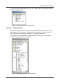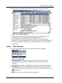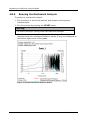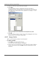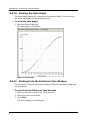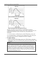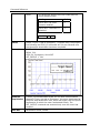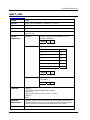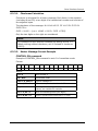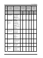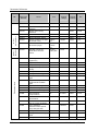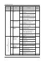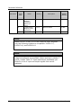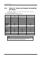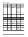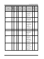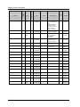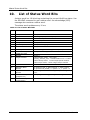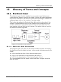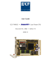
1
XtraWare User Manual XtraWare Version 3.0 (Supporting XtraDrive Versions 3.04 - 3.23) Catalog No. 8U0109 Revision G Copyright © 2007 by YET, YASKAWA Eshed Technology Ltd. XtraWare User Manual XtraWare Version 3.0 for XtraDrive Version 3.04 – 3.23 Cat. No. 8U0109 Rev. G June 2007 All rights reserved. No part of this publication may be stored in a retrieval system, or reproduced in any way, including but not limited to photocopy, photography, magnetic or other recording, without the prior agreement and written permission of the publisher. Program listings may be entered, stored and executed in a computer system, but not reproduced for publication. This manual is designed to provide information about the XtraWare software. Every effort has been made to make this book complete and as accurate as possible. However, no warranty of suitability, purpose or fitness is made or implied. YET Ltd. is not liable or responsible to any person or entity for loss or damage in connection with or stemming from the use of XtraWare and/or the information contained in this publication YET Ltd. bears no responsibility for errors which may appear in this publication and retains the right to make changes to the software and manual without prior notice. MAIN OFFICE: 13 Hamelacha St., Afeq Industrial Estate Rosh Ha’ayin 48091 ISRAEL Tel: +972-3-9004114 Fax: +972-3-9030412 E-mail: [email protected] Homepage: www.yetmotion.com USA OFFICE: YET US Inc. 444 East Industrial Park Drive Manchester, NH 03109-5317 USA Toll Free: 866-YET-8080 Tel: 603-641-1822 Fax: 603-641-1239 E-mail: [email protected] Homepage: www.yet-motion.com Table of Contents Table of Contents 1. INTRODUCTION ......................................................................... 1 2. SYSTEM REQUIREMENTS AND SOFTWARE INSTALLATION ......... 3 3. THE MAIN SCREEN INTERFACE .................................................. 5 3.1. Title Bar (A) ................................................................................................5 3.2. Menu Bar (B)/Toolbar (C) ...........................................................................5 3.2.1. File Menu..................................................................................................6 3.2.2. Edit Menu .................................................................................................8 3.2.3. View Menu ................................................................................................9 3.2.4. Run Menu ............................................................................................... 10 3.3. Communication Menu ................................................................................ 11 3.3.1. Tool Menu............................................................................................... 11 3.3.2. Maintenance Menu ................................................................................... 12 3.3.3. Window Menu.......................................................................................... 13 3.4. Status Bar (D) ........................................................................................... 14 3.5. Work Area (E) ........................................................................................... 14 3.5.1. Workspace Window .................................................................................. 14 3.5.2. Project Tab ............................................................................................. 14 3.5.3. Program Window ..................................................................................... 17 3.5.4. History Window ....................................................................................... 18 3.5.5. Parameters Window ................................................................................. 18 3.5.6. Cam Window........................................................................................... 19 4. OPERATING THE XTRADRIVE USING XTRAWARE ..................... 21 4.1. Connecting the Driver to the PC ................................................................ 21 4.1.1. Communication Settings ........................................................................... 21 4.2. Setup Wizard............................................................................................. 22 4.3. Parameter Control..................................................................................... 25 4.3.1. Uploading and Downloading Parameters...................................................... 25 4.3.2. Viewing Parameter Settings....................................................................... 25 4.3.3. Setting Parameters Online......................................................................... 27 4.3.4. Setting Parameters Offline ........................................................................ 27 4.4. Programming the XtraDrive ...................................................................... 27 4.4.1. Writing a Program.................................................................................... 27 4.4.2. Programming Commands with Variable Arguments ....................................... 29 4.4.3. Running a Program .................................................................................. 32 XtraWare User Manual i Table of Contents 4.5. Program Modes ......................................................................................... 33 4.5.1. Program Mode ......................................................................................... 33 4.5.2. Immediate Mode...................................................................................... 33 4.5.3. Sequential Mode ...................................................................................... 33 4.6. Tuning the Control Loops .......................................................................... 34 4.6.1. Manual Tuning......................................................................................... 34 4.6.2. Auto-tuning ............................................................................................ 34 4.6.3. Performing Fast Tuning............................................................................. 35 4.6.4. Performing Fine Tuning............................................................................. 35 4.6.5. Evaluating Control Loop Performance.......................................................... 36 4.7. Charts ....................................................................................................... 38 4.7.1. The Chart Main Window ............................................................................ 38 4.7.2. Using Zoom ............................................................................................ 42 4.7.3. Starting the Trace.................................................................................... 43 4.7.4. Printing a Chart ....................................................................................... 43 4.8. Mechanical Analysis .................................................................................. 44 4.8.1. Mechanical Analysis Window...................................................................... 45 4.8.2. Mechanical Analysis Toolbar ...................................................................... 47 4.8.3. Running the Mechanical Analysis ................................................................ 48 4.9. ECAM (Electronic Cam).............................................................................. 49 4.9.1. ECAM Profile Characteristics ...................................................................... 49 4.9.2. Installing ECAM ....................................................................................... 49 4.9.3. ECAM Workflow ....................................................................................... 49 4.9.4. ECAM Profiles .......................................................................................... 50 4.9.5. Creating a Profile ..................................................................................... 51 4.9.6. Loading a Profile ...................................................................................... 57 4.9.7. Editing a Profile ....................................................................................... 57 4.9.8. Deleting a Profile ..................................................................................... 58 4.9.9. Viewing the Master-Slave Table ................................................................. 59 4.9.10. Viewing the Data Graph......................................................................... 60 4.9.11. Printing from the Electronic Cam Window ................................................. 60 4.9.12. The Cam List Window............................................................................ 61 4.9.13. Downloading Profiles to the XtraDrive...................................................... 61 4.9.14. Programming with Electronic Cam........................................................... 62 4.9.15. Modifying a Profile using Variables .......................................................... 63 4.9.16. Monitoring Master and Slave Positions ..................................................... 67 4.9.17. Serial Communication and ECAM ............................................................ 67 4.10. Registration and Latching ......................................................................... 70 4.10.1. Latching Workflow ................................................................................ 71 4.10.2. Troubleshooting ................................................................................... 72 4.10.3. Commands .......................................................................................... 72 4.10.4. Registration Variables ........................................................................... 73 4.10.5. Registration Example ............................................................................ 74 4.11. Interrupts ................................................................................................. 76 4.11.1. Interrupt Events ................................................................................... 76 4.11.2. Multiple Interrupts ................................................................................ 76 ii XtraWare User Manual Table of Contents 4.11.3. 4.11.4. 4.11.5. 4.11.6. 4.11.7. 4.11.8. Interrupt Interrupt Interrupt Interrupt Interrupt Interrupt Response Time ....................................................................... 76 Masks.................................................................................... 77 Handling ................................................................................ 77 Variables ............................................................................... 77 Commands............................................................................. 80 Example ................................................................................ 82 4.12. Master-Slave Synchronization ................................................................... 85 4.12.1. Using New_move_enable to Reduce Response Time .................................. 85 4.12.2. Overriding New_move_enable ................................................................ 85 4.12.3. Example Program for a Flying Shear Application........................................ 85 5. COMMAND REFERENCE ............................................................ 87 5.1. XtraWare Modes........................................................................................ 88 5.1.1. Program Mode (User Program Buffer UPB)................................................... 88 5.1.2. Sequential Mode (Sequential Command Buffer SCB) ..................................... 88 5.1.3. Immediate Mode (Immediate Command Buffer ICB) ..................................... 89 5.2. SCB and UPB Command Flushing............................................................... 89 5.2.1. Motion Commands With _D Suffix .............................................................. 89 5.2.2. Motion Commands Without _D Suffix .......................................................... 89 5.3. Motion Modes ............................................................................................ 90 5.3.1. Transition Between Motion Modes............................................................... 91 5.4. Motion Command Buffer............................................................................ 93 5.5. XtraWare Commands................................................................................. 93 ACCELERATION ................................................................................................. 96 ALARM_RESET .................................................................................................. 97 CALL................................................................................................................ 98 CONTROL ......................................................................................................... 99 DELAY............................................................................................................ 100 ECAM_DISENGAGE .......................................................................................... 101 ECAM_ENGAGE ............................................................................................... 102 ELECTRONIC_GEAR ......................................................................................... 103 END............................................................................................................... 104 ENGAGE_VIRTUAL_AXIS................................................................................... 105 EXT_INT......................................................................................................... 106 FAST_OUTPUT_SETTING................................................................................... 107 FAULT_MANAGER ............................................................................................ 110 FAULT_MANAGER_RETURN ............................................................................... 111 FAULT_MESSAGE_CLEAR .................................................................................. 112 GAIN ............................................................................................................. 113 GO ................................................................................................................ 114 GO_D ............................................................................................................ 115 GO_H ............................................................................................................ 116 GO_TO........................................................................................................... 118 HOME Commands ............................................................................................ 118 HARD_HOME................................................................................................... 119 HOME_C......................................................................................................... 120 XtraWare User Manual iii Table of Contents HOME_SW ...................................................................................................... 121 HOME_SW_C .................................................................................................. 122 IF .................................................................................................................. 123 IF_INPUT........................................................................................................ 125 INPUT_CASE ................................................................................................... 127 INT................................................................................................................ 129 INT_RETURN................................................................................................... 131 JERK_TIME ..................................................................................................... 132 LABEL ............................................................................................................ 133 LATCHING_TRIGGER ........................................................................................ 134 LOOP ............................................................................................................. 136 MATH............................................................................................................. 137 MOVE ............................................................................................................ 139 MOVE_D......................................................................................................... 140 MOVE_H......................................................................................................... 141 MOVE_R ......................................................................................................... 142 READ_FROM_ARRAY ........................................................................................ 145 REGISTRATION_DISTANCE ............................................................................... 146 RETURN ......................................................................................................... 147 RUN............................................................................................................... 148 SET_OUTPUT .................................................................................................. 148 SET_OUTPUTS ................................................................................................ 150 SET_VAR ........................................................................................................ 151 SET_ZERO_POSITION ...................................................................................... 152 SLIDE ............................................................................................................ 153 SLIDE_ANALOG ............................................................................................... 154 SPEED ........................................................................................................... 155 SPEED_CONTROL ............................................................................................ 156 SPEED_LIMIT_FOR_TORQUE_MODE ................................................................... 157 START............................................................................................................ 158 STOP ............................................................................................................. 158 STOP_EX ........................................................................................................ 159 STOP_MOTION ................................................................................................ 161 TORQUE ......................................................................................................... 162 TORQUE_ANALOG............................................................................................ 163 TORQUE_LIMITS.............................................................................................. 164 WAIT_EXACT .................................................................................................. 165 WAIT_FOR_START ........................................................................................... 166 WAIT_INPUT ................................................................................................... 167 WAIT_STOP .................................................................................................... 168 WAIT_VAR...................................................................................................... 169 WRITE_TO_ARRAY ........................................................................................... 170 5.6. Serial Communication Commands ........................................................... 171 CLEAR_BUFFER ............................................................................................... 171 ECAM_POINTS ................................................................................................ 171 ECAM_PROFILE ............................................................................................... 172 ECAM_SEGMENT.............................................................................................. 173 ECAM_TABLE_BEGIN........................................................................................ 173 ECAM_TABLE_END........................................................................................... 174 GET_FROM_ARRAY .......................................................................................... 174 GET_PAR ........................................................................................................ 174 iv XtraWare User Manual Table of Contents GET_VAR........................................................................................................ 175 GET_VERSION................................................................................................. 175 POLLING ........................................................................................................ 175 SAVE_PRG_ECAM ............................................................................................ 175 SET_PAR ........................................................................................................ 176 6. SERIAL INTERFACE PROTOCOL .............................................. 177 6.1. Basic Communication Specifications ....................................................... 177 6.2. Protocol Specifications ............................................................................ 177 6.2.1. Message Data Structure.......................................................................... 178 6.2.2. Master Message..................................................................................... 178 6.2.3. Response Message ................................................................................. 183 6.3. Troubleshooting ...................................................................................... 191 7. ERROR MESSAGES ................................................................. 193 8. PARAMETER REFERENCE ........................................................ 211 8.1. Table 19: Parameters .............................................................................. 211 8.2. Table 20: Application Setting Parameters ............................................... 218 8.3. Table 21: Switches .................................................................................. 219 8.4. Table 22: Input Signal Selections ............................................................ 226 8.5. Table 23: Home Switches ........................................................................ 229 8.6. Table 24: Extended Input Signal Selection .............................................. 229 8.7. Table 25: Output Signal Selections.......................................................... 230 8.8. Table 26: Extended Output Signal Selection ............................................ 231 8.9. Table 27: Input and Output Availability per Mode ................................... 232 8.10. Table 28: Auxiliary Functions .................................................................. 233 8.11. Table 25: Monitor Modes ......................................................................... 234 9. LIST OF SYSTEM VARIABLES ................................................. 235 10. LIST OF STATUS WORD BITS .............................................. 244 11. LIST OF OPERATION CODES................................................ 245 XtraWare User Manual v Table of Contents 12. GLOSSARY OF TERMS AND CONCEPTS................................. 249 12.1. Electronic Gear........................................................................................ 249 12.1.1. Electronic Gear Parameters .................................................................. 249 12.2. Motion Profile.......................................................................................... 250 12.2.1. Profile Velocity ................................................................................... 250 12.2.2. Profile Acceleration ............................................................................. 250 12.2.3. Profile Jerk Smoothing Time................................................................. 251 12.3. Explanation of Command Table ............................................................... 251 vi XtraWare User Manual Introduction 1. Introduction The XtraWare software constitutes the user interface and tool of operation for the XtraDrive. It enables the user to set parameters, tune control loops and monitor faults. It also facilitates programming of the driver both for professional programmers and novices. The topics described in this manual include: ♦ Software installation (including system requirements and setup instructions) ♦ User menus and toolbars ♦ Operation of the XtraDrive driver using the XtraWare software (including communication, parameters and program handling) ♦ Command reference which lists alphabetically: The commands used in the XtraWare software The commands available in the serial communication protocol ♦ The XtraDrive serial communication protocol ♦ Error messages ♦ Parameter reference providing information on all the parameters available in the XtraWare software ♦ System Variables ♦ Status Word Bits ♦ Operation Codes Related documents: Title Catalog Number XtraDrive (XD-) SERIES AC SERVO DRIVER User Manual 8U0108 AC SERVO MOTOR INSTRUCTIONS TOE-C231-2 for ∑-II servomotors or other compatible motors XtraDrive (XD-) SERIES AC SERVO DRIVER Short Form Installation Guide 8U0107 XtraWare User Manual 1 1BSystem Requirements and Software Installation 2. System Requirements and Software Installation For optimum performance, XtraWare requires: ♦ ♦ ♦ ♦ Computer: Pentium 166 MHz (Pentium II 350 MHz recommended). At least 32 MB of RAM (64 MB recommended). A hard drive with at least 100 MB of free disk space. Operating System: WindowsTM 95 OSR2 or later (IE4.01 Service Pack 2 or later). Windows 98 Windows NT4.0 Service Pack 3 or later (IE4.01 Service Pack 2 or later) Windows 2000 Windows Me Windows XP ♦ Super VGA or better graphics display, minimum 256 colors (65536 colors recommended). ♦ When using a computer that does not have a serial port, use either a USB-to-serial converter or a PC Card expansion interface (PMCIA) with a serial port. Review vendors’ system requirements for further details, as not all USB-to-serial converters have exhibited satisfactory performance. See Appendix E, page E12 of the XtraDrive User Guide for a description of the cable and pin assignments. ♦ CD-ROM drive (for installation only). The XtraWare software is provided on a CD-ROM supplied with the XtraDrive. To obtain a copy, visit the web site (www.yetmotion.com) and login to the download section. You may also contact your sales representative. Before proceeding with the installation procedure, close any applications that are open. During the procedure, XtraWare and its related files are installed on your hard disk. If a previous version of XtraWare is already installed, the existing program is overwritten. All files created with previous versions of the software should be backed up. XtraWare User Manual 3 1BSystem Requirements and Software Installation ¾ To install XtraWare: 1. Insert the CD into the CD-ROM drive. 2. If the procedure does not start automatically, either: Click Start>Run and type "D:\Install\SETUP" (where D: is your CD drive), or Using Windows Explorer, navigate to the CD-ROM drive, and doubleclick D:\Install\SETUP.EXE. The installation screen is displayed, the installation procedure commences and a message welcoming you to XtraWare is displayed. 3. Click Next to continue. 4. Follow the onscreen instructions to choose a destination folder for the XtraWare files. 5. Click Next to continue. 6. Select the program group to create the XtraWare icon. C:\Program Files\YET\XtraWare is the default setting. 7. After selecting the program group or folder, click Next to continue. The PC files are copied from the CD-ROM. During the procedure, the installation progress is displayed. Note: If new versions of the PC support files are needed to install XtraWare, a window will appear asking whether to overwrite the current version or to cancel the installation. XtraWare may not run correctly if the new versions of the support files are not installed. 4 XtraWare User Manual The Main Screen Interface 3. The Main Screen Interface This chapter describes the XtraWare main screen. The main screen comprises a main toolbar, menus and several windows. A sample main screen is shown in Figure 1 below. For clarity, the screen has been divided into separate elements. Figure 1: Sample Main Screen 3.1. Title Bar (A) The XtraWare title bar displays the name of the currently opened project file. 3.2. Menu Bar (B)/Toolbar (C) The XtraWare menu bar provides access to the XtraWare menus: File, Edit, View, Run, Communication, Tools, Maintenance, Window and Help. The toolbar is located immediately beneath the menu bar. It comprises shortcut icons to the most commonly used XtraWare options. In the following descriptions of the menu options, the appropriate icon (where applicable) is listed next to each option. Note: Some menu options are not available in all modes and will appear as disabled (grayed) when unavailable. Similarly, disabled icons indicate that communication is offline. XtraWare User Manual 5 The Main Screen Interface 3.2.1. File Menu A project contains all the data currently active in XtraWare, such as the user program, parameter settings, and definitions. The File Menu options are used to create new XtraWare projects, open existing projects, and save changes to projects. Project files, which are handled like any other file, are automatically assigned an extension of XDR, for example, project1.XDR. In addition, the File Menu opti programs and parameters. ons are used to download, upload and print Table 1: File Menu Options Option New Project (Ctrl+N) Icon Description Creates a new XtraWare project. When this option is selected, the Motor Selection window in which you select the motor that will be used for this project, is displayed. Figure 2: Motor Selection Window Select the appropriate manufacturer and then one of the listed modules. If you are using a model that is not listed, click Add Another Motor. Enter the name of the model in the Motor Model field and select the Motor Type (either Rotary or Linear). Click Finish to proceed; the Workspace, Program, History and Parameters windows are opened with their default contents. 6 XtraWare User Manual The Main Screen Interface Option Open Project (Ctrl+O) Icon Description Opens an existing XtraWare project. When this option is selected, the Load Project window is opened: Figure 3: Load Project Window Save Project Saves the current project under its existing name. If the project has not yet been named, the Save Project window is opened: Figure 4: Save Project Window In the File name field, type a name for the project and click Save. Save Project as Saves the current project under a new name. When this option is selected, the Save Project window is opened. Close Project Closes the current project. If the project has not been saved, the following message is displayed: Save changes to <project-name>? Click Save to save the project. XtraWare User Manual 7 The Main Screen Interface Option Icon Description Download Program Downloads a program to the XtraDrive driver. Download Parameters Downloads a set of parameters to the XtraDrive driver. Download Cam1 Downloads cam profiles to the XtraDrive driver. Upload Uploads data from the XtraDrive driver. Print Program Prints the current program. Print Parameters Prints the parameter list, including their values, on the printer. The parameters are printed in tabular format. Print Chart Prints the currently displayed chart and its corresponding data. See section 4.7.4, Printing a Chart, for further information. Exit Exits from XtraWare. Note: 1) The ECAM-related options are only activated if an ECAM license has been purchased. 3.2.2. Edit Menu The Edit Menu options are used to edit the command order of a program in the Program window. Table 2: Edit Menu Options 8 Option Description Cut (Ctrl+X) Deletes selected text or lines from the program and places the selection on the Windows and XtraWare clipboards. Copy (Ctrl+C) Places a copy of selected text or lines from the program on the Windows and XtraWare clipboards. Paste (Ctrl+V) Inserts the contents of the XtraWare clipboard into the program. XtraWare User Manual The Main Screen Interface 3.2.3. View Menu The View Menu options are used to select which windows you want displayed on the XtraWare screen. Table 3: View Menu Options Option Icon Description Program Displays/hides the Program window. Parameters Displays/hides the Parameters window. Cam List Displays/hides the CAM window. Workspace Displays/hides the Workspace window. History Displays/hides the History window. Chart Opens the Charts window. See section 4.7, Charts, for a description of this window’s operation. Variable Opens the Variables window: Figure 5: Variables Window Toolbar Displays/hides the toolbar. Status bar Displays/hides the status bar. XtraWare User Manual 9 The Main Screen Interface 3.2.4. Run Menu The Run Menu options enable you to control the program running on the XtraDrive driver. Table 4: Run Menu Options Option Icon Description Run Program Runs the program immediately. Stop Program Stops the program immediately. Servo ON Switches the XtraDrive driver ON so that the motor is now under driver control. In this mode, the driver holds the motor in position under various load conditions, even when no motion is required. Servo OFF Switches the XtraDrive driver OFF so that the motor is no longer under driver control. Immediate Mode Switches to Immediate mode. In Immediate mode, commands are downloaded immediately to the driver’s memory. For details of all the available modes, see section 4.5, Program Modes. Program Mode Switches to Program mode. In Program mode, a list of commands is prepared in the program editor to be downloaded to the driver at a later stage. For details of all the available modes, see section 4.5, Program Modes. Sequential Mode Switches to Sequential mode. In Sequential mode, each command is downloaded individually to the driver and then processed. For details of all the available modes, see section 4.5, Program Modes. Jog Runs the motor at a constant predefined speed. Stop Immediately stops the motor motion. You can also click Stop on the toolbar or press F9. For further details, see the STOP_EX command in Chapter 5, Command Reference. 10 XtraWare User Manual The Main Screen Interface 3.3. Communication Menu The Communication Menu options are used to switch the communication between the XtraWare and the XtraDrive on and off. Options in this menu are used to customize the communication parameters. Table 5: Communication Menu Options 3.3.1. Option Description Online Switches to working in online mode. Offline Switches to working in offline mode. Setting Opens the Communication Settings window. See section 4.1.1, Communication Settings, for details on this option. Tool Menu The Tool Menu options allow you to access the Electronic Cam interface, to automatically tune the control loops, and to perform a mechanical analysis of the motor-load system. Table 6: Tool Menu Options Option Icon Description Electronic Cam1 Creates motion according to a specified profile that is dependent on the position of a master axis or on the elapsed time. Autotuning Automatically sets control loop gains based on actual system measurements and tunes the XtraDrive driver accordingly. See section 4.6, Tuning the Control Loops, for full details. Mechanical Analysis The mechanical analysis (FFT) option samples and analyzes 2000 speed data points. The speed is a response to sinusoidal torque frequency commands. The response is displayed as a graph of the gain (dB) and phase angle (degree) versus frequency (Hz in log scale). According to the graph, the relevant parameters can then be adjusted in order to reduce the effect of the mechanical restrictions. See section 4.8, Mechanical Analysis, for full details. XtraWare User Manual 11 The Main Screen Interface Note: 1) The ECAM related options are only activated if an ECAM license has been purchased. 3.3.2. Maintenance Menu The Maintenance Menu options allow you to tune the control loops automatically or manually, to open and close a log file, and to send a command to the XtraWare device. Table 7: Maintenance Menu Options Option Icon Description Reset Driver Cycles the main circuit and control power supply. This is necessary after certain parameters are edited, to enable the new settings. The Need Reset indicator appears in the status line when this action is necessary. Reset to Default Parameters Discards user modifications to the parameters and reverts to the factory default parameters. Note that some parameters are updated at power-up only and you must therefore restart the XtraDrive after using this option. Open Log File Starts a new log file and inserts all the commands sent via communication into the log file. The log file is used mainly for debugging purposes. When this option is selected, the Open Log File dialog box is displayed: Figure 6: Open Log File Dialog Box Select a directory and select the name of an existing file, or type in a name to create a new log file. When XtraWare is in Online 12 XtraWare User Manual The Main Screen Interface Option Icon Description mode, all the commands sent via communication to the XtraDrive are stored in the selected log file. To close the log file, select the Close Log File option. 3.3.3. Close Log File Stops storing commands in the log file and closes the log file that is currently open. Password Enables an authorized user to enter a password to be permitted to modify certain parameters (displayed in red in the Parameters window) which can only be modified by authorized users. Send Command For internal use only. Window Menu The Window menu is used to switch between different views in the XtraWare system, and to save a customized screen for future use. Table 8: Window Menu Options Option Description Project Screen Displays the default XtraWare Main Screen interface, which includes the Workspace, Program, History, Cam and Parameters windows. Program Edit Screen Enlarges the Program window to facilitate program editing. The History, Cam and Parameters windows are hidden. User Screen Displays the current user customized screen saved under the Save User Screen option. Save User Screen The size and location of the Workspace, Program, History, Cam and Parameters windows can be customized to facilitate your work session. This option enables you to save your customized screen for future work sessions. Each time you save a new customized screen, the previous user screen is overwritten. XtraWare User Manual 13 The Main Screen Interface 3.4. Status Bar (D) The Status Bar, located at the bottom of the XtraWare screen, indicates the status of the current driver and of the Servo. Figure 7: Status Bar The indicators on the right of the status bar are as follows: ♦ A: Indicates whether or not a program is running on the controller (Run or Stop). ♦ B: Need Reset indicator. After certain parameters are edited, the main circuit and control power supply must be cycled in order to enable the new settings. When this indicator appears, click Reset. ♦ C: Indicates the status of the connection to the XtraDrive driver (Offline or Online). ♦ D: Indicates the current status of the XtraDrive driver (ON or OFF). 3.5. Work Area (E) The Work Area comprises the following windows: ♦ ♦ ♦ ♦ ♦ ♦ 3.5.1. Workspace window Project tab Program window History window Parameters window Cam window Workspace Window The Workspace window includes: ♦ Project Tab: The subsections of the current project. ♦ Command Tab: A list of the XtraWare commands divided into six groups. ♦ Description Pane: A description of the currently selected item. 3.5.2. Project Tab The Project tab (Figure 8) presents the subsections (Program, Parameters and Cam) of the current project. 14 XtraWare User Manual The Main Screen Interface To view the project subsections, click the + sign next to the project name in the Workspace window. Figure 8: Workspace Window – Project Tab 3.5.2.1. Command Tab The Command tab (Figure 9) lists the commands that can be used to write the program. The commands are divided into groups. A full description of each command is provided in Chapter 5, Command Reference. To view the commands under a command group, click the + sign next to the group name in the Command tab. Figure 9: Workspace Window – Command Tab XtraWare User Manual 15 The Main Screen Interface The icon next to each command indicates its current status. The availability or unavailability of a command depends on the current working mode. Table 9 below lists the three command tab icons. Table 9: Command Tab Icons Icon Description Available command. This command can be used in the current working mode. Currently selected command. When a command is selected its description is displayed in the Description area under the command list. Command is not available in the currently selected mode. ¾ To select a command: 1. Double-click on the command name. The appropriate command dialog box is displayed. See section 4.4.1, Writing a Program, for details on how to insert commands into the program. 2. Click on a command name to see a short description of the command in the Description pane, or see Chapter 5, Command Reference, for a more detailed description. 3.5.2.2. Command Groups The Command Groups are listed in the table below. Table 10: Command Groups Group 16 Description Included Commands (examples) ECAM Controls the motor motion according to a profile that is dependent on the position of a master axis or on time elapsed. ECAM_ENGAGE; ECAM_DISENGAGE; ECAM_VIRTUAL_AXIS Encoder Latching Controls the latching and registration process. LATCHING_TRIGGER, REGISTRATION_DISTANCE Home Moves the motor to search for the (system) home position. HARD_HOME, HOME_C, HOME_SW, HOME_SW_C, SET_ZERO_POSITION XtraWare User Manual The Main Screen Interface 3.5.3. Included Commands (examples) Group Description Interrupt Specifies the interrupt routines to be run for various interrupt events. EXT_INT, INT, INT_RETURN Motion Controls motor motion. GO, GO_D, GO_H, MOVE, MOVE_D, MOVE_H, MOVE_R, SLIDE, SLIDE_ANALOG, SPEED_CONTROL, START, STOP_EX, TORQUE, TORQUE_ANALOG Motion Profile Changes the default values of speed, acceleration and jerk time. ACCELERATION, JERK_TIME, SPEED Output Sets output ON/OFF. FAST_OUTPUT_SETTING, SET_OUTPUT, SET_OUTPUTS; Program Flow Control Program flow handling commands. CALL, END, GO_TO, IF, IF_INPUT, INPUT_CASE, LABEL, LOOP, RETURN, RUN System Enables and disables SERVO control in the program. Sets gain and torque limits. CONTROL, GAIN, TORQUE_LIMITS, ELECTRONIC_GEAR Variables Sets variable values in the program. MATH, READ_FROM_ARRAY, SET_VAR, WRITE_TO_ARRAY Wait Delays program flow, either for a specified time or until a condition is met. DELAY, WAIT_EXACT, WAIT_FOR_START, WAIT_INPUT, WAIT_STOP, WAIT_VAR Program Window The Program Window (Figure 10) displays the entire program. The program is written by selecting commands from the Command tab, and entering values for the commands’ parameters. See section 4.4.1, Writing a Program, for details on how to write a program. XtraWare User Manual 17 The Main Screen Interface ¾ To change the value of a command’s argument after it has been added to the program: 1. Double-click on the command line to open its window, and enter a new value or values. Figure 10: Program Window 3.5.4. History Window The History window presents a list of all the commands that have been downloaded or sent (in Immediate mode) to the XtraDrive driver. For each command, the following information is displayed: Table 11: History Window Columns 3.5.5. Name Description ID A sequential number assigned to the command. Command The name of the command that was executed. Operation Mode The operation mode (Program, Immediate, Sequential) active when the command was issued. Parameters Window Each project in the XtraWare system comprises a program and parameters. The XtraWare parameters are divided into different parameter groups, and are displayed in the Parameters window (Figure 11). For instructions on how to set parameters, see section 4.3.3, Setting Parameters Online, and section 4.3.4, Setting Parameters Offline. A full list of all the parameters available in the XtraDrive system and their values is provided in Chapter 8, Parameter Reference. 18 XtraWare User Manual The Main Screen Interface The Parameters window is divided into three panes as shown below: Figure 11: Parameters Window ♦ Group pane (A) lists the parameter groups. The parameters in the selected group are displayed in the Parameters pane. ♦ The Parameters pane (B) displays the details of each parameter. Initially, the values displayed for the parameters are the default values. ♦ The Description pane (C) displays a short description of the selected parameter. 3.5.6. Cam Window The Cam window lists all ECAM profiles that have been defined. Figure 12: Cam Window ♦ Download size: Indicates the number of data points that will be downloaded to the XtraDrive when the Download Cam button is pressed. ♦ Profile#: The profiles are identified in the Cam List by their numbers. ♦ Download: Check the checkboxes corresponding to all profiles that should be downloaded to the XtraDrive when the Download Cam button is pressed. ♦ Size: The number of data points in each profile XtraWare User Manual 19 The Main Screen Interface ¾ To view or edit a profile: 1. Double-click anywhere in the row corresponding to the profile number that you would like to view or edit. The Electronic Cam window is opened, with the Position Setting tab displaying the selected profile. See section 4.9, ECAM (Electronic Cam). Note: The ECAM related options are only activated if an ECAM license has been purchased. Contact YET to purchase an ECAM license. 20 XtraWare User Manual Operating the XtraDrive Using XtraWare 4. Operating the XtraDrive Using XtraWare This chapter provides detailed instructions on how to operate the XtraDrive servo driver using the XtraWare software. 4.1. Connecting the Driver to the PC Serial communication is used between the PC and the driver. ¾ To connect the driver to the PC: 1. Connect a communication cable to an available COM port of your PC. Note that XtraWare supports serial communications ports COM1 through COM7. Their usage depends upon available hardware. 2. Connect the other end of the communication table to the CN3 connector on the XtraDrive. 4.1.1. Communication Settings It is important that the communication settings are set correctly. ¾ To change the communication settings: 1. Run the XtraWare software. The default location is: Start > Programs > XtraWare. 2. Select Setting from the Communication menu. The Communication Settings window is displayed. Figure 13: Communication Settings Window XtraWare User Manual 21 Operating the XtraDrive Using XtraWare 3. Set the Port to the correct COM port of your PC (the default is COM1 on most computers). 4. Set the Axis Address. 5. All other communication parameters are predefined and are for display purposes only: Baud Rate – 19200 Parity – Even Data Bits – 7 Stop bits – 1 Flow Control – None 6. Click OK. ¾ To check the communication settings: 1. After changing the communication settings, select Online from the Communications menu. If the communication indicator in the status bar changes to Online for a few seconds and then reverts to Offline, communication between XtraWare and the XtraDrive has not been established. In such cases, check the following: The driver is powered on. The communication cable is connected both to the PC and to the XtraDrive. Select the Setting option from the Communication menu and make sure that the Port is set to the correct COM port of your PC (the default is COM1 on most computers). 4.2. Setup Wizard To facilitate the setup procedure, XtraWare offers a Setup Wizard that guides you through the following steps: ♦ ♦ ♦ ♦ ♦ ♦ ♦ Select Motor – YASKAWA or other Set Reference Command Type – Pn000.1 Set User Units Set Motion Profile Default (see section 12.2) Set End of Motion definitions Set analog input command of Speed and Torque (if required) Set pulse-train settings for master-slave applications (if required) ♦ Set digital I/O ♦ Set PG divider output ratio. 22 XtraWare User Manual Operating the XtraDrive Using XtraWare ¾ To operate the wizard: 1. 2. ♦ ♦ ♦ ♦ ♦ ♦ ♦ Select New Project from the File menu. Follow the instructions on the following Wizard screens: Motor Selection: Select your motor from the list or add a new motor. Basic Selection: Set the control method, usually “programming”. For host controller applications with pulse train output use “Position control (Pulse train)”. For YASKAWA option board (NS300, NS500, etc), set for “YASKAWA Option board”. Set motor direction. Axis address. XtraDrive supports networking of up to 15 drives connected by serial communication. (Use RS 232 for communication with a single XtraDrive and RS422 for use with up to fifteen XtraDrive units.) Set XtraDrive address. Commutation Settings (Only applicable for motors with A quad B encoders): Software commutation (Phase finding) – XtraDrive finds the commutation angle without sensors. This takes several seconds on the first CONTROL ON after powering up. With commutation sensors (Hall sensors) – Some models of XtraDrive support commutation sensors of 5V or 24V. Set according to the sensors’ polarity. User Units: Set user units for position, speed and acceleration. Position units must be in the range of 0.01 – 100. Default Profile: Set default speed, acceleration and jerk (speed and acceleration values are mandatory). The values can be changed in the program using the appropriate commands. Set the end of motion window in the Advance Setting screen. Analog Input: If you plan to use the analog input command, set the following values. Otherwise skip this screen. Ratio between the analog command and the generated speed Ratio between the analog command and the generated torque Pulse Train: Set the following if your application requires pulse-train values. Otherwise skip this screen. Pulse-train form and logic. Electronic gear between the pulse-train and the motor. (See section 12.1 as well as Electronic Gear in the Glossary.) XtraWare User Manual 23 Operating the XtraDrive Using XtraWare If position control (Pn000.1=C) is set, the Position Completed Width screen is enabled. When using programming mode (Pn000.1=D), the equivalent value is set by Pn2C4 (Pulse train synchronization window). Inputs: Allocate digital inputs to system functions. Digital inputs used as general purpose inputs can be referred to simply by their input numbers from within the program. The polarity can be reversed by checking the Reverse polarity checkbox. Outputs: Allocate digital outputs to system functions. If digital outputs are to be used as general purpose outputs simply refer to the output number in the program. Each output can be used either as a system function output or as a general-purpose output. Encoder Output Settings: For a host-controlled application where output pulses (PG out) are required, set the output gear. Otherwise skip this screen. Click Finish to complete the setup and create a parameters file. ♦ ♦ ♦ 3. to download the parameters to 4. Click Download Parameters XtraDrive,. 5. Cycle the power to reset the XtraDrive. 6. You can now proceed to Auto-tuning (See 4.6, Tuning the Control Loops). 24 XtraWare User Manual Operating the XtraDrive Using XtraWare 4.3. Parameter Control In order to control the motor and the peripheral system (such as I/O lines), the XtraDrive requires that certain parameters be set in its memory. Some parameters are automatically set by the system based on the automatic motor identification (when applicable), and some must be set manually. The parameters define data such as current limits, encoder type and I/O configuration, as well as data related to specific user applications (such as the ratio between the encoder resolution and the user units). 4.3.1. Uploading and Downloading Parameters Parameters can be sent from the PC to the XtraDrive (Downloading) or read from the XtraDrive to the PC (Uploading). Note that the Upload function reads and uploads the parameters, the program and all other data currently active in the XtraDrive (excluding ECAM tables). Therefore, it is advisable to save your program prior to using the Upload function to prevent it from being overwritten. ¾ To download parameters: 1. Click Download Parameters on the toolbar. Note: If the motor is not fitted with a serial encoder (SII or W Series) and the project was opened using Open Project and not by running the Wizard, you must enter a password or the motor parameters (highlighted in red) will not be changed. ¾ To upload parameters: 1. Click Upload on the toolbar. Note: This will upload entire project parameters and program. 4.3.2. Viewing Parameter Settings Parameters are set in the Parameters window (Figure 14). This window displays the current values of the project’s parameters. Note that parameter values in the project do not necessarily match the values currently active in the XtraDrive. In order to provide easy access to certain parameters, the parameters can be viewed in groups. The default group setting of the Parameters window is ALL, that is, all available parameters in the system are shown. XtraWare User Manual 25 Operating the XtraDrive Using XtraWare ¾ To display parameters belonging to a specific group in the Value pane: 1. Select one of the predefined groups (e.g., Digital I/O, Servo Control) listed in the Group pane. Figure 14: Parameters Window The fields in the panes of the Parameters window are listed below (from left to right): ♦ Group: Parameter group selection. ♦ Parameter status indication: An asterisk in this column indicates that the value of the parameter has been changed in the PC, but has not been downloaded to the XtraDrive. ♦ Parameter ID: The parameter number. ♦ Value: Current parameter value (0x indicates hexadecimal values). ♦ Min: Minimum value allowed for the parameter. ♦ Max: Maximum value allowed for the parameter. ♦ Units: The units used for the parameter. ♦ Default: The default value for the parameter. ♦ Description: A short description of the parameter functionality. 26 XtraWare User Manual Operating the XtraDrive Using XtraWare 4.3.3. Setting Parameters Online ¾ To set a parameter online: 1. Right-click on the row of the parameter you wish to change. A pop-up window appears (Figure 15) displaying the current value of the parameter. Figure 15: Parameter Setting Window 2. Use the buttons below each digit to change the value of the parameter. Note that the changed value is sent on-line to the XtraDrive. Some values take effect immediately; others are sent to the driver but take effect only after the power is cycled. The Need Reset indicator appears in the status line when this action is necessary. 4.3.4. Setting Parameters Offline ¾ To set a parameter offline: 1. Double-click on the value field of the desired parameter. 2. Enter the desired value. The new value is not sent to the driver automatically (an asterisk appears in the Parameter status indication column). 3. Click the Download icon 4.4. to send the changed values to the driver. Programming the XtraDrive The XtraDrive has built-in programming capabilities. You can write a program that will be executed by the XtraDrive without the need for an external positioning controller. 4.4.1. Writing a Program A program is written by selecting a command from the command list in the Workspace window (Figure 16), and adding it to the Program window. (For a detailed description of the different commands, see Chapter 5, Command Reference.) You must be in Program mode to write a program. XtraWare User Manual 27 Operating the XtraDrive Using XtraWare ¾ To enter Program mode: 1. Click Program Mode in the toolbar, or select the Program Mode option from the Run menu. Figure 16: Workspace Window Figure 17: Program Window The commands in the Workspace window are divided to groups. For further details, see section 3.5.3, Program Window. ¾ To add a command to a program: 1. Open the relevant command group. 2. Double-click the required command to open a pop-up dialog box (Figure 18) relating to the command. Figure 18: Sample Command Pop-up Dialog Box 28 XtraWare User Manual Operating the XtraDrive Using XtraWare 3. Set the arguments required for the command. See section 4.4.2, Programming Commands with Variable Arguments, for instructions on specifying the argument with a variable. 4. Click Program to add the command to the program in the Program window. The maximum length of a program is 180 command lines. If ECAM is enabled, the maximum program length is 99 lines. It is possible to edit the arguments of commands already listed in the Program window: ¾ To edit a programmed command: 1. Double-click a command in the Program window to open the command's pop-up window. 2. Edit the arguments as desired and click Program. ¾ To edit the order of programmed commands: 1. Use the standard Windows operations (Ctrl+X - cut, Ctrl+C - copy, and Ctrl+V - paste) to re-order commands in the Program window. When you have completed the program, it must be downloaded to the XtraDrive. ¾ To download a program to the XtraDrive: 1. Click Download Program 4.4.2. . Programming Commands with Variable Arguments Instead of entering a number to specify the value of an argument, you can set the argument to equal one of the system or user variables. The variables that can be selected depend on the command being programmed. Arguments that can be specified by variables are indicated by the letter V in the Arg columns of the table in Chapter 11, List of Operation Codes, and in the Syntax Arguments section of each command table in Chapter 5, Command Reference. This functionality is available in driver versions 3.0 and upward. XtraWare User Manual 29 Operating the XtraDrive Using XtraWare ¾ To set an argument equal to a variable: 1. Open the relevant command group. 2. Double-click the required command to open a pop-up dialog box relating to the command. 3. Click the arrow at the right of the relevant argument field. A drop-down menu listing available variables is displayed. Figure 19: Sample Command Pop-up Dialog Box 4. Click the required variable. The selected variable name is displayed in the argument field. 4.4.2.1. Example The following example program illustrates how arguments can be specified by variables. In the program, a sequence of movements is performed. The motion characteristics of each movement are dependent on the value of the digital inputs. For each combination of digital inputs, a different set of values are assigned to the variables that set the motion characteristics. The main part of the program (lines 8 to 16) sets the profile velocity and initiates motion. Once a pre-specified position has been passed, the speed is reduced. Once the commanded motion has ended, a second motion back to the origin is started. 500 ms after the second motion has ended, the program restarts. Most of the commands used in the main section use variables to specify the value of the arguments. Depending on the initial state of the inputs, the program calls (in lines 4 and 6) a different subroutine The variable values are set under labels 3 and 4. 30 XtraWare User Manual Operating the XtraDrive Using XtraWare Evaluation of Digital Inputs 1 LABEL 1 2 WAIT_INPUT 1 = 0 -1 3 WAIT_INPUT 1 = 1 -1 4 INPUT_CASE 12 4 5 CALL 3 6 INPUT_CASE 12 12 7 CALL 4 8 LABEL 2 9 SET_VAR Profile_velocity Var_03 10 GO_H Var_01 11 WAIT_VAR Position_actual_value > Var_02 12 SET_VAR Profile_velocity Var_04 13 WAIT_STOP -1 14 GO_D 0 Var_05 15 DELAY 500 16 GO_TO 1 Main Subroutine 3 17 LABEL 3 18 SET_VAR Var_01 100000 19 SET_VAR Var_02 50000 20 SET_VAR Var_03 1000 21 SET_VAR Var_04 400 22 SET_VAR Var_05 -1 23 RETURN Subroutine 4 24 LABEL 4 25 SET_VAR Var_01 200000 26 SET_VAR Var_02 80000 27 SET_VAR Var_03 1300 28 SET_VAR Var_04 700 29 SET_VAR Var_05 600 XtraWare User Manual 31 Operating the XtraDrive Using XtraWare 30 RETURN The chart below graphs the target speed against time for each of the two cases specified in lines 4 and 6, which call the variable settings specified in subroutines 3 and 4 respectively. For example, note how the initial peak in target speed for Case 2 exceeds that for Case 1. This is because line 9 sets the profile velocity equal to the value of Var_03. Case 1 specifies Var_03 as 1000 user speed units, while Case 2 specifies Var_03 as 1300 user speed units. Therefore, the initial peak in speed in Case 2 exceeded that in Case 1. Figure 20: Graph Illustrating Effect of Variable Argument Settings 4.4.3. Running a Program When a program has been completed and downloaded, it can be run using any of the following methods: ♦ Clicking the RUN icon to run the program from the first line. ♦ In Immediate and Sequential modes, selecting the RUN command from the Program Flow Control commands in the Workspace window. In the pop-up window that is displayed, type in the label number from which you want the program to run. ♦ After downloading a user program to the driver, it is possible to run it automatically every time the driver turns ON by setting the parameter Pn2CC to 1. For further information, see section 7.11 of the XtraDrive User Manual. 32 XtraWare User Manual Operating the XtraDrive Using XtraWare 4.5. Program Modes XtraDrive has three programming modes: ♦ Program ♦ Immediate ♦ Sequential Each mode utilizes an individual buffer for commands and program processing and execution. Note that not all of the commands are available in all the program modes. A full explanation on the use of the buffers is provided in the introductory section of Chapter 5, Command Reference. 4.5.1. Program Mode Use this mode when writing a program that is to be executed after the entire program has been written (see section 4.4.1, Writing a Program). This mode stores the program in the User Program Buffer (UPB). Program execution is activated by the RUN command (see section 4.4.3, Running a Program). 4.5.2. Immediate Mode Use this mode to issue a single command for immediate execution or when sending a single command from a host PC (for example, to change the state of an output while a program is running or to lower the gain while the motor is enabled and not in motion and no program is running). Commands sent in Immediate Mode are stored in the Immediate Command Buffer (ICB) and are executed within 2 ms (or less). 4.5.3. Sequential Mode Use this mode when using a host PC that sends a command stream that should be executed as a program (move the motor and wait for motion completion; wait for input; make another move, etc.). Immediate mode cannot be used in such cases because commands like MOVE_D (move the motor and wait for motion completion) are not available in Immediate mode. XtraWare User Manual 33 Operating the XtraDrive Using XtraWare 4.6. Tuning the Control Loops The mathematical coefficients of the control loop, an advanced control algorithm, must be tuned in order to ensure good system behavior. These coefficients can be tuned either manually or automatically (Autotuning). Two Auto-tuning procedures are available: one that calculates the coefficients based only on the user-specified motor inertia ratio (Fast Tuning), and one that sets the coefficients experimentally by moving the motor and analyzing its behavior (Fine Tuning). 4.6.1. Manual Tuning Manual tuning can be performed according to the instructions provided in the XtraDrive User Manual. 4.6.2. Auto-tuning Auto-tuning is applicable in programming mode only (Pn000.1 = D). In driver version 2.91, auto-tuning is not available for linear motors. When you select the Auto-tuning option from the Maintenance menu, the Auto-tuning window (Figure 21) is displayed: Figure 21: Auto-tuning Window 34 XtraWare User Manual Operating the XtraDrive Using XtraWare The fields and options are explained below: ♦ Inertia Ratio (Pn103): Inertia ratio between the load and the motor as a percentage. ♦ Fast Tuning: The driver loads a group of parameters from predefined tuning groups, based on the motor and driver type and the load inertia. ♦ Fine Tuning: The driver moves the motor back and forth and searches for the parameters that allow the best system performance. ♦ Auto Select Parameters: Uses Fast Tuning gains as the starting point. The motion profile of the motor while tuning is determined automatically according to system characteristics. The motor will make approximately one turn to each side, and this process is repeated until all coefficients have been set. ♦ With User Parameters: The gain values start at their current values (set by parameters, such as Pn1AC = 54). The motion during the tuning (auto-tuning profile) is set according to Pn2C8, Pn2C9, Pn2CA and Pn2CB, allowing you to specify how far and how fast the motor should turn during fine tuning. 4.6.3. Performing Fast Tuning ¾ To perform fast tuning: 1. Enter a rough estimation of load inertia in Inertia Ratio. 2. Click Start. The Fast-Tuning window is displayed. 3. Click OK. 4. Enable the servo control and check the performance (See 4.6.5, Evaluating Control Loop Performance). If the motor behavior is good you can either perform Fine Tuning or leave it as is. 5. If you are not satisfied with the performance, the following methods can be used to improve the performance and stability of the system: Adjust the global gain (Pn1A0). For very rigid systems, re-run fast tuning after disabling the OCA option. Set a different Inertia ratio. Note: The value of the command filter is calculated automatically and stored in parameter Pn216 during fast tuning. 4.6.4. Performing Fine Tuning During fine tuning the motor moves in the positive direction and then back again, and repeats this motion several times. The control parameters are XtraWare User Manual 35 Operating the XtraDrive Using XtraWare optimized by analyzing the motor movement. Motor movement is as follows: ♦ If you select Auto Select Parameters the motor will rotate approximately twice. ♦ If you select With User Parameters the motor will rotate according to the settings of the auto-tuning parameters (Pn2C8 – Pn2CB). ¾ To perform fine tuning: 1. Place the motor so that it can move according to the auto-tuning profile. 2. Enter a rough estimation of load inertia in the Inertia Ratio field. 3. Select Auto Select Parameters or With User Parameters, depending on the motor motion required. 4. Press Start. Warning: After pressing Start, the motor will begin to move. 5. Wait for a few minutes while the best gain is detected. 6. Click OK. 7. Enable the servo control and check the performance (see 4.6.5, Evaluating Control Loop Performance). If you are not satisfied you can easily improve the performance and stability by adjusting the global gain (Pn1A0) or by trying the following. For very rigid systems, try the fine tuning without the OCA option selected. Set a different Inertia ratio. 4.6.5. Evaluating Control Loop Performance After having tuned the control loop coefficients using either manual or automatic tuning, it is useful to verify that the coefficients chosen result in adequate control. The procedure detailed below describes how the quality of the control coefficients can be checked. 36 XtraWare User Manual Operating the XtraDrive Using XtraWare ¾ To evaluate control loop performance: 1. Click Program Mode to select Program mode. 2. Enter the program shown below in Figure 22 (see section 4.4, Programming the XtraDrive). Figure 22: Program for Checking Control Coefficients 3. Click Program Download XtraDrive. to download your program to the to open the Chart window. 4. Click Chart 5. In the Graph Setting area, set Smoothed Target Speed to 50. 6. Click Start Trace . The message Waiting for trigger and data collection completion is displayed. to run the program. 7. Click Run Program The program runs and the data is uploaded. A graph of the motion is displayed. 8. Study the graph, particularly the Position Error, shown by default in yellow, and decide whether the control coefficients are set appropriately. Figure 23: Sample Chart of Position Error XtraWare User Manual 37 Operating the XtraDrive Using XtraWare 4.7. Charts The Charts option provides a graphical display of signals over a specified time period. Two analog signals and two digital I/O signals can be displayed. 4.7.1. The Chart Main Window Select the Charts option from the View menu to display the Chart Main window (Figure 24). Figure 24: Chart Main Window 38 XtraWare User Manual Operating the XtraDrive Using XtraWare 4.7.1.1. Trigger A trigger is a device used to specify exactly when data collection should begin. The trigger can be made conditional on any of a range of aspects of the servo operation. For example, you can specify that data collection should begin after the /COIN signal is set ON or after the speed feedback exceeds 100 rpm. A trigger condition is specified by four settings: ♦ Source - Trigger object selection Specifies the variable on which the trigger is conditional. Any one of the variables listed in the Y1, Y2, I/0 –1 and I/O – 2 fields can be selected from the drop-down menu. Figure 25: Trigger Selection (1) ♦ Slope - Edge Type Specifies in which direction across the trigger Level the Source must change to trigger data collection. Figure 26: Trigger Selection (2) As the type of slope, select: Rising Edge: Data collection is triggered when the value of the Source rises from below the trigger Level to above the trigger Level, i.e., when the change is from LO to HI in I/O. Falling Edge: Data collection is triggered when the value of the Source falls from above the trigger Level to below the trigger Level, i.e., when the change is from HI to LO in I/O. Data Change: Data collection is triggered when the value of the Source crosses the trigger Level in either direction. No Trigger: Data collection will start at the same time as Start Trace is clicked. All other trigger settings are irrelevant. ♦ Level - Trigger Level Specifies the threshold value of the Source at which data collection is triggered. The units for the setting are the same as those of the trigger XtraWare User Manual 39 Operating the XtraDrive Using XtraWare object selected in Source. The trigger level cannot be set if the trigger object is I/O 1 or I/O 2. ♦ Pre-Trigger (0% to 99%) A buffer of data is collected even prior to the trigger condition being met. This allows XtraWare to include the period before the trigger in the graph. The Pre-Trigger setting specifies how long this period should be, as a percentage of the duration of the graph after the trigger. 4.7.1.2. Graph Settings For all of the graph settings described below, you can select the scale (available values are 1, 2, 5, 10, 25, 50, 100, 500, 1000) and the color in which the results will be displayed. ♦ X – Sampling Time Interval Specifies the time interval for obtaining trace data (default: 25ms). The total trace time for which results are obtained is the sampling time interval multiplied by 10. ♦ Y1 / Y2 – Sampled Channel Available values are: Target Speed Smoothed Target Speed Acceleration Motor Speed Position Error Torque Reference ♦ I/O 1 / I/O 2 – Sampled Digital I/O Select the sampled output and input signals. 4.7.1.3. Show Select the objects that will be displayed in the graph. 4.7.1.4. Caption Enter the caption to be displayed in the graph. 40 XtraWare User Manual Operating the XtraDrive Using XtraWare 4.7.1.5. Chart Toolbar The chart toolbar is shown below. Figure 27: Chart Toolbar The toolbar icons are explained in the following table. Table 12: Chart Toolbar Icon Definitions Option ICON DESCRIPTION Save Chart Saves a copy of the trace graph to a specified file. Open Loads a trace data file. Up one zoom level Restores the previous zoom level. Reset zoom Restores the area shown in the window to its normal size. Start Trace Starts the trigger searching. Click the icon again to cancel the search. Enable Measure Measures the delta values of X, Y1 and Y2 by right-clicking and dragging the mouse. The values are displayed on the respective axes. Show markers Displays information on current cursor location. Driver Units Toggles graph units between user units and encoder counts. Save graph as picture Saves the graph in bmp format enabling you to view the graph with other software packages. Save Saves graph data in Excel format (*.csv). XtraWare User Manual 41 Operating the XtraDrive Using XtraWare 4.7.2. Using Zoom The view of an area selected by the mouse can be magnified. ¾ To zoom in on an area: 1. Position the mouse at one corner of the area you want to select. 2. Hold down the left mouse button and drag to the opposite corner. A white area will appear around the selected area. 3. Release the left mouse button. The selected area of the graph is enlarged. 4. Click Reset zoom to view the original graph. 5. Click Up one zoom level to view the previous zoom level. Figure 28: Chart Zoom Feature 42 XtraWare User Manual Operating the XtraDrive Using XtraWare 4.7.3. Starting the Trace ¾ To start a trace: 1. In the Chart main window, click Start Trace . A message Waiting for trigger and data collection completion is displayed 2. To cancel the trace, click Start Trace again. Otherwise, click Run to run the program. When the conditions are met and the trigger is applied, a message Uploading data is displayed. 3. Click Cancel if you want to halt the data sampling process, otherwise wait until the process ends. The Chart main window is displayed once the specified data has been obtained. Notes: 1. Sometimes the trigger cannot be detected in under 2 ms due to the characteristics of the detection period. 2. If the sampling time is increased, XtraWare may continue to wait for the trigger even after the trigger has been applied. XtraWare waits because data for the sampling time is saved in the XtraDrive after the trigger has been applied. 4.7.4. Printing a Chart The chart and data of the Chart main window can be printed. ¾ To print a chart: 1. Select the Print Chart option from the File menu while the chart is open. XtraWare User Manual 43 Operating the XtraDrive Using XtraWare 4.8. Mechanical Analysis Controlling a system (amplifier, motor, and load) requires knowledge of its mechanical restrictions, such as resonance and anti-resonance frequencies. The mechanical analysis (FFT) option samples and analyzes 2000 speed data points. The speed is a response to sinusoidal torque frequency commands. The response is displayed as a graph of the gain (dB) and phase angle (degree) versus frequency (Hz in log scale). Using the graph, the relevant parameters can then be adjusted in order to reduce the effect of the mechanical restrictions. Note: The process uses the predefined parameters of Notch Filter (Pn408.0, Pn409, Pn40A) and does not take control gains into consideration. ¾ To start mechanical analysis: 1. Click FFT or select Mechanical Analysis from the Tools menu. A Warning message is displayed (Figure 29): Figure 29: Mechanical Analysis Warning Message 44 XtraWare User Manual Operating the XtraDrive Using XtraWare 2. Click OK to open the Mechanical Analysis window (Figure 30). 4.8.1. Mechanical Analysis Window Figure 30: Mechanical Analysis Window Accurate measurement of the frequency characteristics depends on the settings of the following parameters: ♦ Sampling Time [μsec] (Measurement Frequency [Hz], Excitation Time [ms]) If the sampling time is shortened, a higher frequency can be measured and the excitation time is shortened. However, frequency resolution deteriorates and measurement accuracy is reduced at low measuring frequency. The measuring frequency and excitation time depend on the sampling time. To begin with, set the sampling time to a small value. Then reset it to a more appropriate value in accordance with the results produced. ♦ Excitation Amplitude [±%/Rated torque] Range: 1 to 300% Must be set to a value below the Torque Limit. Select the size of the reference amplitude applying excitation to the machine as a percentage of the ratio of size to rated torque. A larger excitation amplitude tends to give more correct measurements, but an excessively large amplitude can cause overspeed (A.51) and overcurrent (A.10) alarms. Problems with the load inertia and the XtraWare User Manual 45 Operating the XtraDrive Using XtraWare balance would cause alarms, and accurate measurements would be impossible. Note: Accurate measurement is not possible if the torque is restricted during excitation. Refer to the XtraDrive User Manual for details on the Torque Limit function. ♦ Allowable Rotations [Rotation] Range: ±1 to 1000 rotations The number of Allowable Rotations must be set so the measurements can be taken safely. Set the motor revolutions so the setting is within the operable range. Select the limit of motor rotations during measurement. If the allowable number of rotations is exceeded, the zero clamp function will cause the motor to stop and measurements will be halted. Consider the deceleration ratios for the pulley radius, ball screws, and so on, and then select a number of motor rotations. When reducing the number of motor rotations, also reduce the excitation amplitude and the sampling time. The allowable rotations acts as restriction for each excitation period. In multiple excitation applications, the excitation start position might shift. Check the range of motion each time excitation is applied. Detection of the allowable rotation in the XtraDrive may be delayed by a maximum of 2ms. If so, operation may exceed the settings due to factors such as inertia size and interference from speed. Include a margin when setting the allowable number of rotations. ♦ No. of Executions [Set] Range: 1 to 5 Select the number of times that the measurements should be taken for an average measurement to be calculated. A motion set is a back-andforth operation that starts excitation or measurement from the forward side and excitation/measurement from the reverse side. More measurement iterations tend to yield more accurate measurements, but the time required for measurement increases. ♦ Excitation Signal (fixed): Excites the machine with cycle wave. ♦ Graph Setting: Select the graph scale or leave the default setting of AUTO for automatic scale setting. Select the colors of the lines used in the graph of the measurement results. ♦ Caption: Enter the caption to be displayed in the graph. 46 XtraWare User Manual Operating the XtraDrive Using XtraWare 4.8.2. Mechanical Analysis Toolbar The mechanical analysis toolbar is shown below. Figure 31: Mechanical Analysis Toolbar The following table explains the function of each icon: Table 13: Description of Mechanical Analysis Toolbar Icons Option ICON DESCRIPTION Save Chart Saves the current analysis include the settings and the graph. Open Opens a previously saved analysis. Print Prints the currently displayed chart and its corresponding data. Up one zoom level Restores the previous zoom level. Reset zoom Restores the area shown in the window to its normal size. Enable Measure Dragging the cursor by left-clicking the mouse enables the measurement of the difference (delta) between the ends of the line. The delta values are displayed in each axis label. Leftclicking in a new location starts a new measurement. Show markers Shows exact value of a point. A yellow cross reflects the movement of the mouse and the exact value can be seen in each axis label. Save graph as picture Saves graph in bmp format enabling you to view the graph without the need for the XtraWare software. Export graph data Saves graph data in Excel format (*.csv). XtraWare User Manual 47 Operating the XtraDrive Using XtraWare 4.8.3. Running the Mechanical Analysis To perform a mechanical analysis 1. Run the motor to excite the machine and measure the frequency characteristics. 2. Run the process by pressing the START button. Warning: The motor will begin moving once Start has been pressed. Once the process is completed, a graph is displayed. The values of resonance and anti resonance frequency values (if any) are displayed at the bottom right corner of the graph. Figure 32: Sample Mechanical Analysis Output 48 XtraWare User Manual Operating the XtraDrive Using XtraWare 4.9. ECAM (Electronic Cam) Cam creates motion according to a specified profile, depending either on the position of a master axis or on time elapsed. The ECAM feature allows you to specify the position that a slave axis must reach, depending on the position of a master axis or on the time elapsed. The XtraDrive allows up to four profiles to be specified per project. Each profile can be comprised of a maximum of 16 segments, and may contain up to 256 data points. 4.9.1. ECAM Profile Characteristics The following must be considered when designing a profile: ♦ Up to four different profiles can be defined simultaneously. ♦ Each profile can be divided into a maximum of 16 segments. ♦ An ECAM table may contain up to 256 data points. To avoid exceeding this limit, do not specify unnecessarily small Master Step values. ♦ The maximum slave step is 32767 user position units. The maximum master step (after scaling) is 32767 counts. 4.9.2. Installing ECAM To enable the ECAM functionality, see the document Instructions for License Setting. 4.9.2.1. Verifying that ECAM is Installed ¾ To verify that ECAM is installed: 1. Open XtraWare. 2. From the Communication menu, select On-Line to enter on-line mode. to upload a project from the XtraDrive. 3. Click Upload Project 4. Open the File menu. If the Download Cam option in the File menu is enabled, the installation was successful. 4.9.3. ECAM Workflow When working with ECAM, the following process is followed: ♦ Designing the ECAM Profile: You define the profile using XtraWare. XtraWare automatically generates a Master-Slave table. The Master-Slave table is downloaded to the XtraDrive. XtraWare User Manual 49 Operating the XtraDrive Using XtraWare ♦ Programming an Application: CAM motion is engaged or disengaged upon external events or logical conditions. ♦ Running a Program: The profile table can be adjusted by applying a shift or offset, or by scaling the master or slave positions. 4.9.4. ECAM Profiles A profile defines the relationship between the motion of the master and the motion of the slave. The profile dictates the required slave position for a given master position. The graph below illustrates a typical profile. Figure 33: Example of an ECAM Profile A profile consists of a number of segments. For example, the profile shown consists of four segments: the first stretches from Master Position 0 to 100, the second from 100 to 200 and so on. You need only specify the start and end points of each segment; XtraWare interpolates between those points according to shape specified. XtraWare can interpolate along straight lines and sinusoidal curves. You define the resolution (the distance between consecutive data points in the profile) with which the curve must be generated. The profile created should be smooth to ensure smooth motion. 4.9.4.1. Time based Profiles – Virtual Axis XtraWare also allows you to specify a time based profile, where the XtraDrive’s internal clock generates the master pulses. A pulse is generated every 125 μs. In this case, the Master Position axis is in fact a time axis. 50 XtraWare User Manual Operating the XtraDrive Using XtraWare 4.9.5. Creating a Profile Profiles are defined in the Electronic CAM window. 4.9.5.1. Adding a Profile ¾ To add a profile to your project: 1. Select Electronic CAM from the Tool menu, or click Electronic Cam on the toolbar. The Electronic CAM window is displayed. 2. Enter a number that you will use to identify the profile in the Profile Number field. 3. Click Add Profile. The profile is added to the Profile List. 4.9.5.2. The Position Setting Tab Profiles are defined on the Position Setting tab of the Electronic CAM window. ¾ To open the Position Setting tab: 1. Click the Position Setting tab. The Position Setting tab is displayed. Each field is explained below. Figure 34: Position Setting Tab ♦ Segment#: Each segment is automatically assigned a number. ♦ Master Start: The first segment starts at master position 0. Each subsequent segment starts at the position at which the previous segment ended. The master position is defined in terms of master encoder counts. ♦ Master End: Specifies the master position at the end of the segment. If a time based profile is being created, Master End specifies the time at which the segment ends. For example, if the segment is to span 100 ms, the difference between the Start and End values must be 800 ms as the clock generates eight pulses per millisecond. ♦ Slave Start: The first segment starts at slave position 0. Each subsequent segment starts at the position at which the previous segment ended. The slave position is defined in terms of position user units. XtraWare User Manual 51 Operating the XtraDrive Using XtraWare ♦ Slave End: Specifies the slave position at the end of the segment. ♦ Master Step: Specifies the distance required between the points that are interpolated between the start and end points. The greater the step size, the lower the resolution will be. When the start and end points are to be joined simply by a straight line, set Master Step to the distance between the start and end points, as no points need be interpolated between them. ♦ Curve Shape: Specifies whether the start and end points of the segment are to be joined by a straight line, by a portion of a sinusoidal graph, or by a user-defined array. 4.9.5.3. Defining the Master and Slave End Points ¾ To define the master and slave end points of each segment that makes up the profile: 1. Enter the master position (in terms of encoder counts or clock pulses) at the end of the first segment in the Master End field. 2. Enter the slave position (in position user units) at the end of the first segment in the Slave End field. 4.9.5.4. Defining the Segment Resolution The resolution is set by specifying the distance between successive points in the segment: ¾ To set the resolution: 1. Enter the distance (in encoder counts or clock pulses) between the points that XtraWare should generate by interpolation in the Master Step field. A lower setting will result in more points being generated and in a smoother motion. 4.9.5.5. Defining the Interpolation Method Once the end points and the resolution of a segment have been specified, specify how the positions of the remaining points in the segment must be calculated. The number of points generated is dependent on the Master Step setting. 52 XtraWare User Manual Operating the XtraDrive Using XtraWare ¾ To set the interpolation method: 1. Click in, or tab to, the Curve Shape field. 2. Click the icon that is displayed in the Curve Shape field. The Curve Shape window is displayed. Figure 35: Curve Shape Window 3. Select a curve shape from the drop-down menu: Straight Line: Points will be generated by interpolation to join the start and end points with a straight line. Array: Instead of selecting a shape for XtraWare to generate by interpolation, you can specify all the points directly. See section 4.9.5.6, Specifying an Array. sin(-90 to 90), sin(0 to 90), sin(-90 to 0): Points will be generated by interpolation to join the start and end points with the required section of a sinusoidal graph. 4. Click OK. A new line for the next segment is displayed in the Position Setting tab with the Master Start and Slave Start fields filled in automatically. 5. Continue filling in the table until every segment in the profile has been defined. 4.9.5.6. Specifying an Array Instead of specifying a curve shape along which points must be interpolated, XtraWare allows you to specify each point directly. You can either specify the points within the XtraWare interface, or you can import a file created in a spreadsheet program. The number of points to be specified is dependent on the Master Step setting. For example, consider the following specification. Figure 36: Example of End Point Specification The length of the segment is 1000 master counts and the Master Step is 20. The number of points in the segment, including the start and end points is thus 51. XtraWare User Manual 53 Operating the XtraDrive Using XtraWare ¾ To open the Curve Shape window: 1. First specify the values of Master End, Slave End and Master Step, as explained previously in sections 4.9.5.3 and 4.9.5.4. 2. Click in, or tab to, the Curve Shape field. 3. Click the icon that is displayed in the Curve Shape field. The Curve Shape dialog box is displayed. 4. Select Array from the Curve Shape window. A table is displayed in the Curve Shape window. Each row corresponds to one point in the segment. For the example shown above, a table with 51 rows will be displayed. The slave values for the first and last points are entered automatically, based on the Slave Start and Slave End values specified. Only the slave values need be entered – the master values are calculated automatically, based on the end points and the master step value. Figure 37: Example of Curve Shape Window with Array Table Entering the values directly into the table ¾ To enter the values into the Curve Shape table: 1. Enter the values in the Slave Value column. Note that the first and last values are entered for you, according to the values you assigned to Slave Start and Slave End. 2. Click OK. The Curve Shape window is closed. Array will be displayed in the Curve Shape column of the Position Setting table. 54 XtraWare User Manual Operating the XtraDrive Using XtraWare Importing the values into the table XtraWare allows you to import data into the array table. This allows you to prepare an array in a spreadsheet and then import it. The following specifications must be adhered to when creating the file: ♦ The number of rows in the spreadsheet must be the same as the number of rows in the table displayed in the Curve Shape window. ♦ The slave values of the first and last points must be the same as those in the table displayed in the Curve Shape window. ♦ The spreadsheet table may have any number of columns. ♦ The slave values must be located in the right-most column. ♦ The values may have any number of digits after the decimal point, but XtraWare will import only the integer part of each value. For example, 1.79 will be imported as 1. ♦ The file must be saved in CSV format. ♦ The file must not be in use by other software while being imported into XtraWare. A sample spreadsheet is shown in Figure 38 below. Figure 38: Sample Spreadsheet for Array Import ¾ To import the values into the Curve Shape table: 1. Click Import in the Curve Shape window. The Import window is displayed. XtraWare User Manual 55 Operating the XtraDrive Using XtraWare 2. Select the CSV file in which the array is saved. 3. Click Open. The Curve Shape window is redisplayed, and the array table is completed with the values specified in the imported file. Note that only the integer part of each value will be imported. For example, 1.79 will be imported as 1. Figure 39: Example of Curve Shape Menu with Completed Array Table 4. Click OK. The Curve Shape window is closed. Array will be displayed in the Curve Shape column of the Position Setting table. 4.9.5.7. Saving A Profile After a profile has been created, it must be saved. ¾ To save a profile: 1. Click Save in the Cam Profile File area. The Save Cam Profile dialog box is displayed. 2. Enter a name for the profile file in the File name field, select a folder in which to save the file, and click Save. The file is saved with an .XDP extension. 56 XtraWare User Manual Operating the XtraDrive Using XtraWare Note: After downloading a profile, it is saved in the XtraDrive. Unlike parameters and programs which can be uploaded from the XtraDrive to XtraWare, ECAM tables cannot be uploaded. Thus, it is important that profiles are saved on a disk for backup purposes. 4.9.5.8. Completing a Profile ¾ To complete your profile definition: 1. Once you have completed the profile, click Finish. 2. The Electronic Cam window is closed. 4.9.6. Loading a Profile You can load and use profiles that have previously been saved. It does not matter if the profile was originally written for a different project. ¾ To load a profile: 1. Select Electronic CAM from the Tool menu, or click Electronic Cam on the toolbar. The Electronic CAM window is displayed. 2. Enter a number that you will use to identify the profile in the Profile Number field. 3. Click Add Profile. The profile is added to the Profile List. 4. Click on the Position Setting tab. 5. Click Open in the Cam Profile File area. The Open Cam Profile dialog box is displayed. 6. Select the file to open, and click Open. The segments of the opened profile are listed in the Position Setting tab. 4.9.7. Editing a Profile 4.9.7.1. Inserting Additional Profile Segments ¾ To insert a segment between existing segments in a profile: 1. Click any field in the row of the segment before which the new segment should be inserted. 2. Click Insert. A new line is inserted. Enter the required data to define the new segment. XtraWare User Manual 57 Operating the XtraDrive Using XtraWare 4.9.7.2. Deleting a Segment ¾ To delete a segment: 1. Click any field in the row of the segment that is to be deleted. 2. Click Delete. The selected segment is deleted. 4.9.7.3. Editing Values in the Position Setting Table ¾ To edit an entered value: 1. Click the field that you would like to change. 2. Enter the new value. The value is changed, and the table values are automatically updated: If the value of a Master End position is changed, all subsequent Master End values are automatically adjusted so as to maintain the size of the segments as they were before the change. Changing a Master End value therefore affects only the size of the segment that the point ends. (The Master Start values are also updated to match the revised Master End values.) Changing the value of a Slave End position does not result in subsequent Slave End values being updated – only the next Slave Start value is updated. 4.9.8. Deleting a Profile ¾ To delete a profile: 1. Select the profile to be deleted from the Profile List. 2. Click Delete Profile. Warning: Clicking Delete Profile deletes the profile immediately – you will not be asked for confirmation. 58 XtraWare User Manual Operating the XtraDrive Using XtraWare 4.9.9. Viewing the Master-Slave Table The Data List tab displays all the interpolated points through which the slave will move, listed per segment. ¾ To view the Master-Slave table: 1. Open the Data-List tab. 2. Click on one of the segments listed on the left panel of the Data List tab. The master-slave table is displayed on the right, listing all of the interpolated points, as well as the specified start and end points of the selected segment. Figure 40: Data List Table XtraWare User Manual 59 Operating the XtraDrive Using XtraWare 4.9.10. Viewing the Data Graph The data graph graphically represents the specified table. The dots along the curve represent the interpolated points. ¾ To view the data graph: 1. Open the Data Graph tab. The data graph is displayed. Figure 41: Data Graph 4.9.11. Printing from the Electronic Cam Window The contents of each of the Position Setting, Data List and Data Graph tabs can be printed: ¾ To print from the Electronic Cam Window: 1. Select the profile to print from the Profile List. 2. Select the tab to be printed. 3. Click Print. The Print dialog box is displayed. 60 XtraWare User Manual Operating the XtraDrive Using XtraWare 4. Make any necessary changes to the settings shown and click Print. 4.9.12. The Cam List Window By default, the Cam List window is displayed on the project screen. If the window is not displayed, ensure that Cam list is checked in the View menu. Figure 42: Cam List Window ♦ Download size: Indicates the number of data points that will be downloaded to the XtraDrive when the Download Cam button is pressed. ♦ Profile#: The profiles are identified in the Cam List by their numbers. ♦ Download: Check the checkboxes corresponding to all profiles that should be downloaded to the XtraDrive when the Download Cam button is pressed. ♦ Size: The number of data points in each profile. ¾ To view or edit a profile: 1. Click anywhere in the row corresponding to the profile number that you would like to view or edit. The Electronic Cam window is displayed with the Position Setting tab displaying the selected profile. 4.9.13. Downloading Profiles to the XtraDrive A profile is not transferred to the XtraDrive until you download it. ¾ To download a profile: 1. Ensure that the relevant Download checkboxes in the Cam List window are checked. on the toolbar. 2. Click Download Parameters The profiles are downloaded to the XtraDrive. Note: After downloading a profile, the profile is saved in the XtraDrive, but unlike parameters and programs, which can be uploaded from the XtraDrive to XtraWare, profiles cannot be uploaded. Thus, it is important that profiles are saved on a disk for backup purposes. XtraWare User Manual 61 Operating the XtraDrive Using XtraWare 4.9.14. Programming with Electronic Cam Programming commands are used to initiate and terminate movement according to an ECAM profile. 4.9.14.1. ECAM_ENGAGE Format: ECAM_ENGAGE <Profile_ID> <Mode> This command is used to initiate motion according to an ECAM profile. You must specify the profile number according to which the slave must move, as well as whether the motion should continue indefinitely (Cyclic mode), or only until the profile has been completed once (Non Cyclic mode). Figure 43: Programming an ECAM_ENGAGE Command 4.9.14.2. ECAM_DISENGAGE Format: ECAM_DISENGAGE This command is used to terminate ECAM motor motion. ECAM_DISENGAGE will cause the motion to stop only once the current profile is completed. To stop the motion immediately, use the STOP_EX command. 62 XtraWare User Manual Operating the XtraDrive Using XtraWare 4.9.14.3. ENGAGE_VIRTUAL_AXIS Format: ENGAGE_VIRTUAL_AXIS <Profile ID> <Direction> This command is used to start ECAM motion when a time based profile is being used. In this case, the XtraDrive clock acts as the master and generates a pulse every 125 μs (8 pulses every millisecond). In this case, the horizontal axis of the profile is in terms of clock ticks. You must specify the profile number according to which the slave must move, as well as whether the profile should be followed in the positive or negative direction. Figure 44: Programming an ENGAGE_VIRTUAL_AXIS Command 4.9.15. Modifying a Profile using Variables The XtraDrive includes functionality that allows you to stretch and shift a profile without having to redefine each segment. Simply by adjusting the values of variables, you can: ♦ ♦ ♦ ♦ Stretch the profile horizontally by adjusting the Master scale. Stretch the profile vertically by adjusting the Slave scale. Shift the profile horizontally. Offset the profile vertically. 4.9.15.1. Profile Scaling The Master scale can be adjusted by multiplying it by a fraction A/B. If A/B is larger than one, the profile will be stretched. If A/B is less than one, the profile will be contracted. ♦ A, the numerator, is defined by the variable ECAM_Master_scale_num. ♦ B, the denominator, is defined by the variable ECAM_Master_scale_den. For example, if a scaling factor of 2/3 was applied to the profile shown below, the Master axis would be contracted by a third. XtraWare User Manual 63 Operating the XtraDrive Using XtraWare Figure 45: Sample Profile Before Adjustment Figure 46: Sample Profile After Master Axis Scaling Similarly, the profile can be stretched or compressed vertically by multiplying the Slave scale by a fraction C/D. If C/D is larger than one, the profile will be stretched. If C/D is less than one, the profile will be contracted. ♦ C, the numerator, is defined by the variable ECAM_Slave_scale_num. ♦ D, the denominator, is defined by the variable ECAM_Slave_scale_den. The scaling factors cannot by changed while ECAM is engaged. ¾ To apply scaling: 1. Set the variables ECAM_Master_scale_num, ECAM_Master_scale_den, ECAM_Slave_scale_num and ECAM_Slave_scale_den using the SET_VAR command. Note: When using a virtual axis, it is recommended that scaling only be used to scale the graph down, that is, A/B and C/D should be set to values lower than one. If a profile is stretched, a lack of sufficient data points will result in a profile that is not smooth. When designing a profile, you should therefore design it for the largest movements that could possibly be required, so that it will only ever be necessary to scale the profile down, not up. 64 XtraWare User Manual Operating the XtraDrive Using XtraWare Note: The scaling factors discussed above do not affect the size of the shift or offset, if defined. 4.9.15.2. Shift By applying a positive shift, the profile graph is shifted in the negative direction along the master position axis. Conversely, by applying a negative shift, the profile graph is shifted in the positive direction along the master position axis. Figure 47: Illustration of the Application of Shift The shift is specified as an absolute distance from the origin of the profile graph. In the case of a cyclic profile, the next profile will be followed as it was originally specified, unless a different shift is specified. ¾ To apply a shift: 1. Set the value of the variable ECAM_Shift using the SET_VAR command. Note: The size of the shift is not affected by scaling the master axis XtraWare User Manual 65 Operating the XtraDrive Using XtraWare 4.9.15.3. Offset By applying an offset, you can shift a profile vertically. A positive offset shifts the profile upward, increasing the slave position reached at each master position. A negative offset shifts the profile downward, reducing the slave position reached at each master position. The following graphic illustrates a positive offset. Figure 48: Illustration of the Application of a Positive Offset ¾ To apply an offset: 1. Set the value of the variable ECAM_Offset using the SET_VAR command. Note: The size of the offset is not affected by scaling the slave axis. Both shifts and offsets can be applied during motion. This will usually result in a sudden, jolting motion as the target slave position is adjusted instantly across a discontinuity. When applying a shift before engaging ECAM motion, ensuring that the profile is shifted to a point at which the slave position is zero will ensure a smooth initial motion. Applying an offset will always result in a sudden change to the target slave position. When the application of a shift or offset does result in a sudden change to the target slave position, the resulting motion will be constrained by the maximum torque settings, not by the default profile settings. The maximum torque settings in each direction are defined by the variables Forward_Torque_Limit and Reverse_Torque_Limit. (Use the TORQUE_LIMITS command to temporarily reduce those values.) Reducing the limits will result in smoother motion at a discontinuity caused by a shift or offset. 66 XtraWare User Manual Operating the XtraDrive Using XtraWare 4.9.16. Monitoring Master and Slave Positions The variable ECAM_Master_profile_position reflects the current position of the master. The variable ECAM_Slave_profile_position reflects the current position of the slave, as dictated by the profile. 4.9.17. Serial Communication and ECAM This chapter has described how ECAM profiles are created and downloaded to the XtraDrive using XtraWare. ECAM profiles can also be sent to the XtraDrive by a host, using serial communication. For more information on using serial communication, see Chapter 6, Serial Interface Protocol. 4.9.17.1. ECAM Commands for Serial Communication The following commands are used to send an ECAM profile to the XtraDrive, using serial communication. More information on these commands is available in Chapter 5, Command Reference. ♦ ECAM_TABLE_BEGIN: Clears any existing table from the XtraDrive and initializes the new table. ♦ ECAM_PROFILE: Specifies the identifying number of the profile that is to be loaded. ♦ ECAM_SEGMENT: Defines the range of the master values covered by the next segment that is to be defined, and specifies the size of the increments between consecutive points. ♦ ECAM_POINTS: Specifies the difference between the slave positions of consecutive points. ♦ ECAM_TABLE_END: Finalizes the ECAM table that has been loaded. 4.9.17.2. Example of Using Serial Communication to Send an ECAM Table to the XtraDrive The code that follows downloads an ECAM table as specified in Table 14: Sample ECAM Table, and illustrated in Figure 49: Sample ECAM Profile. ECAM_TABLE_BEGIN ECAM_PROFILE 1 ECAM_SEGMENT 200 10 0 ECAM_POINTS 4 0 2 3 4 ECAM_POINTS 4 6 6 8 9 ECAM_POINTS 4 9 11 12 12 ECAM_POINTS 4 13 14 14 15 ECAM_POINTS 4 15 15 16 16 XtraWare User Manual 67 Operating the XtraDrive Using XtraWare ECAM_SEGMENT 100 100 0 ECAM_POINTS 1 140 ECAM_SEGMENT 200 10 0 ECAM_POINTS 4 15 16 15 15 ECAM_POINTS 4 15 14 14 13 ECAM_POINTS 4 12 12 11 9 ECAM_POINTS 4 9 8 6 6 ECAM_POINTS 4 4 3 2 1 ECAM_TABLE_END Figure 49: Sample ECAM Profile 68 XtraWare User Manual Operating the XtraDrive Using XtraWare Table 14: Sample ECAM Table XtraWare User Manual 69 Operating the XtraDrive Using XtraWare 4.10. Registration and Latching The latching function is used to capture the position of the motor encoder or external encoder when signaled to do so by a digital input. Latching is performed within 62.5μs of the digital input being received. The registration function is used to stop motion in a predefined distance once an input has been received. For example, a MOVE_H command could have been used to cause the motion shown below. Registration terminates the motion prematurely after an input has been received. The solid line in the graphic below illustrates the motor motion that results due to the input changing from 0 to 1. The dashed line illustrates how the motor would have moved had the input not been received. Figure 50: Illustration of Motion Terminated by Registration In the diagram: ♦ D1: The delay between the input being received and registration beginning. ♦ D2: The predefined registration distance. ♦ The dashed line in the Velocity graph represents the motion that would have taken place had the input not been received. Note: Only input 6 (CN1-46) is used to trigger registration. There is no need to set In_6 to function as a latch input. 70 XtraWare User Manual Operating the XtraDrive Using XtraWare 4.10.1. Latching Workflow The registration process is described below. Detailed instructions for the use of the commands and variables are provided in the sections that follow. ♦ Define a condition for latching using the LATCHING_TRIGGER command. Possible conditions are: Input 6 (connected at CN1-46) changes from 0 to 1 (Rising Edge). Input 6 (connected at CN1-46) changes from 1 to 0 (Falling Edge). ♦ Start motion: The registration process can be applied in the following motion modes: Position, Velocity, Hunting, Pulse-Train, Analog Speed. See section 5.3, Motion Modes. ♦ After 62.5ms of the condition being met: The variable Latched_position_ready changes from 0 to 1. The variable Latched_motor_position is set to the current position of the motor, in position user units. The variable Latched_master_position is set to the current position of the master (if in use), in encoder counts. ♦ Perform the next step only once the Latched_position_ready variable has changed from 0 to 1. Use the command WAIT_VAR <Latched_position_ready> or assign an interrupt conditional on this variable. ♦ Define the distance from where the input is received to where the motor must stop using the REGISTRATION_DISTANCE command. The deceleration caused by registration is defined by the variable Profile_acceleration. When specifying the registration distance, ensure that it is sufficiently long for the motor to be able to decelerate to a stop at the profile acceleration. ♦ The motor decelerates to a stop. Under certain circumstances, the motor will not stop at the point command by REGISTRATION_DISTANCE. See 4.10.2, Troubleshooting. XtraWare User Manual 71 Operating the XtraDrive Using XtraWare 4.10.2. Troubleshooting In certain circumstances, the motor will not stop at the point specified by the registration process. The value of the variable Motion_status indicates how the motion ended. 1. The motor traveled further than the registration distance, but not as far as the target position of the original motion command. This will occur if the registration distance is not sufficiently long for the motor to be able to decelerate to a stop at profile acceleration (see section 12.2.2, Profile Acceleration). Either increase the registration distance, or increase the profile acceleration. 2. The motor stopped at the target position specified by the original motion command, as if registration had not occurred. This will occur if the latching condition was not met. To ensure that the motor will stop by registration, increase the distance to be traveled specified by the motion command. 4.10.3. Commands Two commands are required when using latching: one to enable and define a condition for latching, and another to define the stopping distance once the condition has been met. 4.10.3.1. LATCHING_TRIGGER Format: LATCHING_TRIGGER <Condition> This command enables latching and specifies the condition that must be specified for latching to begin. Specifically, once this condition has been met, the variable Latched_position_ready is set from 0 to 1. Figure 51: Programming a LATCHING_TRIGGER Command The three conditions that can be chosen are: ♦ Off: Setting this condition cancels any previous LATCHING_TRIGGER command. ♦ Rising Edge: Registration will be triggered when Input 6 (which is connected at CN1-46) changes from 0 to 1. ♦ Falling Edge: Registration will be triggered when Input 6 (which is connected at CN1-46) changes from 1 to 0. 72 XtraWare User Manual Operating the XtraDrive Using XtraWare Figure 52: Rising and Falling Edge Conditions 4.10.3.2. REGISTRATION_DISTANCE Format: REGISTRATION_DISTANCE <Distance> This command causes the motor to decelerate to a stop a specified distance from the point at which the motor position was latched (Latched_motor_position). The distance over which the deceleration occurs is specified by the <Distance> argument, which is specified in user position units. Note the following: ♦ The rate at which the motor will decelerate is governed by the profile acceleration (See section 12.2.2, Profile Acceleration). ♦ The motor will stop at the requested position unless the distance required for the deceleration exceeds the remaining motion distance. ♦ The variable Motion_status indicates whether the motion ended as commanded by the REGISTRATION_DISTANCE command. See section 4.10.4.3, Motion_status. ♦ This command executes immediately and it should thus be preceded in the program by a command that delays its execution until latching has been completed. Use the command WAIT_VAR Latched_position_ready = 1 or an interrupt conditional on this variable to ensure that REGISTRATION_DISTANCE is executed only once latching has been completed. 4.10.4. Registration Variables There are four variables related to registration. Latched_position_ready acts as a flag to indicate when the latching condition has been met. The Latched_motor_position and Latched_master_position variables record the positions of the controlled motor and of the master (if applicable) at the instant the condition is met. Finally, the Motion_status variable indicates whether the registration movement was performed. 4.10.4.1. Latched_motor_position This variable records the position of the motor when the latching condition was met. Because the sampling time is 62.5 μs, the accuracy of the latching XtraWare User Manual 73 Operating the XtraDrive Using XtraWare is dependent on the motor speed and the exact moment in the sampling interval at which latching takes place. The position is recorded in terms of user position units. 4.10.4.2. Latched_master_position This variable records the position of the master axis when the latching condition was met. Because the sampling time is 62.5 μs, the accuracy of the latching is dependent on the motor speed and the exact moment in the sampling interval at which latching takes place. The position is recorded in terms of master counts. 4.10.4.3. Motion_status This variable indicates how the motion ended. Motion_status has four possible states: ♦ 0 (Not in motion): Motor not in motion. ♦ 1 (Stopped by registration): The latching condition was met during motion, and the motion was stopped by registration. ♦ 2 (Motion stopped but not in registration requested position): The latching condition was met during motion, but the registration distance exceeded the remaining motion distance. The motion thus ended normally, but further than the registration distance. ♦ 3 (Still in motion): The latching condition has not been met, and the motor is still in motion. 4.10.4.4. Latched_position_ready This variable indicates whether or not the latching condition has been met. The variable has two possible states: ♦ 0: The latching condition has not yet been met. ♦ 1: The latching condition has been met. This variable is automatically set to 0 by the LATCHING_TRIGGER command. It is set to 1 once the latching data has been processed (this may take up to 4 ms). 4.10.5. Registration Example The following short example program illustrates the use of the commands and variables discussed above. Speed 300 Sets the speed for the MOVE_H command. LATCHING_TRIGGER Rising Edge Sets latching condition. 74 XtraWare User Manual Operating the XtraDrive Using XtraWare MOVE_H 5000 Starts motion. WAIT_VAR Latched_position_ready = 1 Delays next command until variable changes to 1. REGISTRATION_DISTANCE 100 Starts registration movement to stop 100 user position units after latching condition is met. XtraWare User Manual 75 Operating the XtraDrive Using XtraWare 4.11. Interrupts When an event for which an interrupt has been defined occurs, program execution is postponed while the specified interrupt service routine is executed. This allows the XtraDrive to react to events regardless of when they occur. Typical interrupt events include the onset of an emergency situation or changes in user inputs or in user or system variables. 4.11.1. Interrupt Events Interrupt events can be either: ♦ External, such as a change in an input from one value to another, or ♦ Internal, such as a variable value meeting a given condition. 4.11.2. Multiple Interrupts The XtraDrive provides for eight different interrupts to be specified for a single program. Each interrupt is assigned an identifying number from 0 to 7. The identifying number also assigns priority, where: ♦ Interrupt 0 has the highest priority. ♦ Interrupt 7 has the lowest priority. Only one interrupt can be assigned to each priority level. If multiple interrupts occur simultaneously, the interrupt service routines will be run, one at a time, in order of priority. If, while an interrupt routine is being executed, a new interrupt of a higher priority occurs, the program will exit the present interrupt service routine and handle the higher priority interrupt service routine. Once that service routine has been completed, the program will continue handling the lower priority interrupt service routine. Once all the required service routines have been executed, the program will continue at the return point specified by the last interrupt service routine completed. 4.11.3. Interrupt Response Time The maximum response time to the highest priority interrupt is 2 ms. Each lower priority interrupt is handled only once all higher priority interrupt service routines have been completed. 76 XtraWare User Manual Operating the XtraDrive Using XtraWare 4.11.4. Interrupt Masks Using masks, you can specify which interrupt events need be handled, and which need not be. This allows you to specify interrupt service routines for a number of possible events, and then to deactivate them from within the program as required. If no mask is specified, the program will not react to any interrupt event. An interrupt mask must therefore always be specified if interrupt are to be used. See section 4.11.6.2, Interrupt_mask. 4.11.5. Interrupt Handling The process that occurs when an interrupt occurs is summarized below. Detailed instructions on the use of the various variables and commands are provided in the sections that follow. ♦ Event Occurs: External event, such as a change in an input value or ♦ ♦ ♦ ♦ ♦ ♦ Internal event, such as a system variable meeting some condition. Interrupt is registered: The relevant bit in the variable Interrupt_request is set to 1. If the registered interrupt is masked in Interrupt_mask, the program flow is interrupted: The XtraDrive stops retrieving commands from the user program buffer. The XtraDrive executes the interrupt service routine for the highest priority interrupt received. The XtraDrive clears the relevant bit in the variables Interrupt_request and Interrupt_pending to indicate that the interrupt has been cleared. The XtraDrive executes the interrupt service routines for any other outstanding interrupts, in order of priority. The XtraDrive continues running the program: Either from the program line where it was initially interrupted or From another location specified in the interrupt service routine. 4.11.6. Interrupt Variables The XtraDrive uses three variables (registers), each of which is a system variable. Each variable consists of eight bits, one for each interrupt labeled 0 to 7. XtraWare User Manual 77 Operating the XtraDrive Using XtraWare These variables are: ♦ Interrupt_request: Lists interrupt events that have occurred. ♦ Interrupt_mask: Used to specify which interrupt to ignore. ♦ Interrupt_pending: Lists the interrupts that are to be handled. Each of these variables is discussed in detail below. 4.11.6.1. Interrupt_request When an interrupt event occurs, the corresponding bit in the Interrupt_request variable is set to 1. Once the corresponding interrupt service routine has been completed, the bit in the variable is reset to 0. The values of the bits are read/write, therefore interrupts can be reset from within the program using the SET_VAR command. This allows you, for example, to clear all interrupts from within one interrupt service routine. Clearing an interrupt cancels the execution of the associated interrupt service routine. However, if an interrupt is cleared from within its own interrupt service routine, the interrupt service routine will be completed first. The values of the bits of Interrupt_request are set using the SET_VAR command. The value of the variable must be set in decimal format. For example, to set bits 0 and 1 to 1, and all other bits to 0, Interrupt_request would have to be set to 3, which in binary form is 0000011. 4.11.6.2. Interrupt_mask By setting a mask, you can specify to which interrupts the XtraDrive should react and which should be ignored. This allows you to specify interrupt service routines for a number of interrupts, and to then enable or disable each interrupt from within the program. By setting a bit in the variable to 1, the corresponding interrupt is enabled. Setting a bit corresponding to an interrupt that has already occurred to 0 does not prevent the execution of its interrupt service routine, but does prevent the interrupt from being handled again. The values of the bits of Interrupt_mask are set using the SET_VAR command. The value of the variable must be set in decimal format. For example, to set bits 1 and 2 to 1, and all other bits to 0, Interrupt_mask would have to be set to 6, which in binary form is 0000110. Note that by default, all bits in Interrupt_mask are set to 0, and thus by default none of the interrupts will be handled. The command SET_VAR must be used to change the value of the mask variable so as to enable an interrupt. 78 XtraWare User Manual Operating the XtraDrive Using XtraWare The Interrupt_mask variable is reset to zero each time the program is started (by the RUN command or the auto start switch). Therefore, the Interrupt_mask must be set each time. 4.11.6.3. Interrupt_pending The Interrupt_pending variable indicates which interrupts are to be handled. The value of a bit in Interrupt_pending is only set to 1 (indicating that the interrupt is to be handled) if both of the following conditions are met: ♦ The interrupt event has occurred and the corresponding bit in Interrupt_request has been set to 1. ♦ You have enabled the interrupt in the mask register, Interrupt_mask. Once the corresponding interrupt service routine has been completed, the bit in the variable is reset to 0. Interrupt_pending is a read-only variable, and its values thus cannot be changed by the user. 4.11.6.4. Example of Interrupt Variable Functioning Interrupt_mask: To specify that only interrupts 3 and 7 be handled, should their conditions be met, bits 3 and 7 in the variable Interrupt_mask must be set to 1 and all other bits must be set to 0, as shown: Bit# 7 6 5 4 3 2 1 0 Setting 1 0 0 0 1 0 0 0 Variable value: Interrupt_mask = 136 Interrupt_request: If the interrupt conditions for interrupts 1, 3 and 4 are met, then bits 1,3 and 4 in the variable Interrupt_request will be set to 1 and all other bits will be set to 0. Bit# 7 6 5 4 3 2 1 0 Setting 0 0 0 1 1 0 1 0 Variable value: Interrupt_request = 26 XtraWare User Manual 79 Operating the XtraDrive Using XtraWare Interrupt_ reg: Because only bit 3 is set to 1 in the Interrupt_mask variable, only interrupt 3 will be handled; interrupts 4 and 1 will be ignored. Only bit 3 in Interrupt_pending will be set to 1, as it is the only bit set to 1 in both Interrupt_request and Interrupt_mask: Bit# 7 6 5 4 3 2 1 0 Setting 0 0 0 0 1 0 0 0 Variable value: Interrupt_pending = 8 4.11.7. Interrupt Commands Commands are used to signal the beginning and the end of each interrupt service routine. The commands INT and EXT_INT signal the beginning of interrupt service routines, and specify the internal or external interrupt conditions respectively. The command INT_RETURN signals the end of the interrupt service routine, and specifies the program line to which to return. 4.11.7.1. EXT_INT Format: EXT_INT <Priority> <Input_Number> <Edge> This command indicates the beginning of an interrupt service routine when the interrupt is conditional on the value of an external input. The argument <Priority> specifies the interrupt priority. <Priority> is specified as a value from 0 to 7, where 0 is the highest priority and 7 is the lowest. <Input_Number> specifies the number of the digital input to be monitored. <Edge> specifies whether the interrupt is to be triggered when the value of the digital input changes from 0 to 1 (Rising), from 1 to 0 (Falling), or whenever it changes (Both). Figure 53: Programming an EXT_INT Command 4.11.7.2. INT Format: INT <Priority> <Variable> <Condition> <Value> This command indicates the beginning of an interrupt service routine, and is used when the interrupt is conditional on the value of an internal variable. The argument <Priority> specifies the input priority. <Priority> is specified 80 XtraWare User Manual Operating the XtraDrive Using XtraWare as a value from 0 to 7, where 0 is the highest priority and 7 is the lowest. <Variable> specifies on which internal variable the interrupt is conditional. Any XtraDrive variable can be used. <Condition> and <Value> specify the interrupt condition. As shown in Figure 54, any of the relational operators can be specified for <Condition>. <Value> is entered in decimal format. Figure 54: Programming an INT Command 4.11.7.3. INT_RETURN Format: INT_RETURN <Label> This command signals the end of an interrupt service routine. <Label> specifies the program label to which the program must proceed once the interrupt service routine has been completed. Setting <Label> to –1 specifies that the program must simply continue running from the point at which the interrupt occurred. If an interrupt service routine of a lower priority interrupt is executed after a higher priority interrupt service routine, the program will continue from the position defined by the last INT_RETURN command. Figure 55: Programming an INT_RETURN Command XtraWare User Manual 81 Operating the XtraDrive Using XtraWare 4.11.8. Interrupt Example The following example program illustrates the use of interrupts. (The indented lines comment on the lines above.) SET_VAR Interrupt_mask 3 Activates Interrupt 0 and 1. LABEL 2 SET_OUTPUT 1 OFF Sets Output 1 value to 0. WAIT_INPUT 1 = 1 -1 Waits for In 1 to become True. CONTROL ON Starts the servo. MOVE_D 655360 -1 Moves motor 655360 UU at profile speed. SET_OUTPUT 1 OFF Sets Output 1 value to 0. END Program ends. INT 0 Target_velocity >= 400 Interrupt service routine 0: Runs if Target_velocity variable is equal to or exceeds 400. 10. SET_OUTPUT 1 ON Sets Output 1 value to 1. 11. INT_RETURN -1 Returns to program line at which the interrupt occurred. 12. EXT_INT 1 1 Falling Interrupt service routine 1: Runs if In 1 becomes False. 13. STOP_EX Emergency Servo OFF Stops the motion and turns the servo off. 14. INT_RETURN 2 Returns to program to label 2. 82 XtraWare User Manual Operating the XtraDrive Using XtraWare The program will execute differently depending on whether or not In 1 changes during motion, as explained below. Case 1: In 1 does not change during motion Figure 56: Interrupt Example – Output Chart Case 1 From the chart: ♦ The motor started moving after In 1 became true. ♦ As the motor target speed reached 400, output 1 was set to ON as interrupt 0 was invoked as a result of its condition (Target_velocity>=400) being met. ♦ The program returned to the MOVE_D command. ♦ Once the motor completed its motion, the output was set to OFF. XtraWare User Manual 83 Operating the XtraDrive Using XtraWare Case 2: In 1 changes during motion Figure 57: Interrupt Example – Output Chart Case 2 From the chart: ♦ The motor started moving after In 1 became true. ♦ As the motor target speed reached 400, output 1 was set to ON as interrupt 0 was invoked as a result of its condition (Target_velocity>=400) being met. ♦ In 1 became false. ♦ The motor was stopped at the emergency deceleration by the interrupt service routine for interrupt 1. ♦ The program jumped to label 2. ♦ Output 1 was set OFF. Note: If both interrupts occur simultaneously, the interrupt of priority 0 will be handled as in case 1, and then the interrupt of priority 1 will be handled as in case 2. The program will then return to label 2. 84 XtraWare User Manual Operating the XtraDrive Using XtraWare 4.12. Master-Slave Synchronization For master-slave applications, synchronization is generally started by a digital input. Starting the synchronization process as quickly as possible thereafter is extremely important to ensure accurate synchronization. Any delay will result in an unwanted offset between master and slave positions. The command MOVE_R is used to commence synchronization. Conditioning the MOVE_R command using the WAIT_INPUT command will result in a delay of up to 2 ms, which may cause too great a position error between the master and slave. The New_move_enable flag can be used to reduce the delay to 125 μs. 4.12.1. Using New_move_enable to Reduce Response Time The New_move_enable input can be used to reduce the response time to 125 μs. A parameter, Pn2D1.1, is set to activate this feature. Once the flag has been set, all motion commands (except when in Speed Control mode, see section 5.3 Motion Modes) will be delayed until the input has been received. The remainder of the program will continue to run. It is important that a WAIT_INPUT command (or any other wait statement) be issued after the motion command that is to be delayed, to ensure that the rest of the program is also delayed. 4.12.2. Overriding New_move_enable The New_move_enable function can be overridden by setting the variable Override_new_move_enable to 1. Doing so results in all following motion commands being run without the program waiting until a New_move_enable input is received. 4.12.3. Example Program for a Flying Shear Application The program below controls the implementation of a simple flying shear. The parameter Pn2D1.1 is set to 0, mapping the New_move_enable input to input terminal CN1-40. 1. 2. 3. 4. 5. 6. 7. 8. LABEL 1 MOVE_R 0 WAIT_VAR Follower_synchronized = 1 SET_OUTPUT 1 ON WAIT_VAR Position_demand_value >= 1000 SET_VAR Override_new_move_enable 1 GO_D 0 -1 SET_VAR Override_new_move_enable 0 XtraWare User Manual 85 Operating the XtraDrive Using XtraWare 9. GO_TO 1 10. END The command MOVE_R 0 (line 2) is suspended until an input is received at CN1-40. Once the slave is synchronized to the master (line 3), Output 1 is set On (line 4). Once the Position_demand_value variable has exceeded 1000 (line 5), the New_move_enable function in disabled (line 6). Therefore, the GO_D function (line 7) is run immediately, irrespective of the state of the New_move_enable input. The New_move_enable input is then re-enabled (line 8), and the program returns to the beginning (line 9). See MOVE_R in Chapter 5, Command Reference. 86 XtraWare User Manual Command Reference 5. Command Reference This chapter provides a reference for the use of all XtraWare commands. Before the details of the actual commands are presented, some general topics relating to XtraWare’s handling of commands are presented: ♦ 5.1 XtraWare Modes: Describes the three modes of XtraDrive operation, as they relate to command handling. ♦ 5.2 SCB and UPB Command Flushing: Describes how commands are processed through the XtraDrive’s command memory buffers. ♦ 5.3 Motion Modes: Explains the differences between different classes of motion commands. ♦ 5.4 Motion Command Buffer: Explains how the motion command buffer (MCB) processes motion commands. The actual command reference tables are then presented: ♦ 5.5 XtraWare Commands: Reference tables for programming commands. ♦ 5.6 Serial Communication Commands: Reference tables for serial commands. XtraWare User Manual 87 Command Reference 5.1. XtraWare Modes Three modes of operation are available: ♦ Program Mode. ♦ Sequential Mode. ♦ Immediate Mode. 5.1.1. Program Mode (User Program Buffer UPB) In this mode, a program (a group of commands) is downloaded into the UPB (User Program Buffer) of the driver. Program commands have the highest priority. Program execution is activated by the RUN command or by clicking RUN on the toolbar. Motion commands in program mode are first calculated and then inserted into the motion command buffer (MCB). This enables the setting of an output or insertion of a certain term immediately after the motion begins until it ends. Commands with the suffix _D are fetched to the MCB. Only after their completion (i.e., the MCB is empty) is the next command fetched. 5.1.2. Sequential Mode (Sequential Command Buffer SCB) In this mode, each command is placed in the SCB (Sequential Command Buffer) and processed sequentially. If no program is running, a command in the SCB is executed immediately after the previous command in the SCB has been executed. In sequential mode, motion commands that are executed through the MCB are handled as follows: A motion command fetched from the SCB is moved into the MCB. The MCB will then execute the motion command after the previously sent motion command has been completed. Note: When you issue a motion command (MOVE, MOVE_D, GO, GO_D, SLIDE), the motion is calculated internally by the controller and then placed in a “motion queue” inside the motion command buffer (MCB). Therefore, changes made in profile commands (ACCELERATION, SPEED, JERK) in Immediate mode do not affect motions that are already in the MCB. 88 XtraWare User Manual Command Reference 5.1.3. Immediate Mode (Immediate Command Buffer ICB) In immediate mode, commands are placed in the ICB and executed immediately. If a program is running or sequential commands are being executed, an immediate command is fetched only when a delay in the program or the sequential commands occurs. For example, when a MOVE_D command is executed, it pauses the execution of subsequent commands. During that pause, commands from the immediate command buffer can be fetched and executed. An exception is the STOP_EX command, which is executed immediately. 5.2. SCB and UPB Command Flushing Motion command flushing from the SCB or UPB depends on the command type: 5.2.1. Motion Commands With _D Suffix These commands are flushed from the SCB or UPB only when the corresponding movement is terminated according to the precision requirement setting, that is, subsequent commands in the buffer are executed immediately following movement termination of the _D command. For example, setting an output will occur at the end of the movement. 5.2.2. Motion Commands Without _D Suffix These commands are transferred to the MCB, and are flushed from SCB or UPB immediately following execution. This enables you to enter a number of motion commands. While the motion commands are being executed by the driver, other commands can be executed sequentially. XtraWare User Manual 89 Command Reference 5.3. Motion Modes The motion commands are divided into Motion modes as described below. The current motion mode can be read from the Motion_mode variable. ♦ Position: Motion commands (MOVE, GO, MOVE_D, GO_D) are calculated and a trajectory movement speed and duration are determined. ♦ Velocity: The velocity command (SLIDE) can be sent and changed at any time while keeping acceleration and jerk within the limits defined by the relevant variables. ♦ Torque: The TORQUE command is immediately applied to the motor. The torque changing rate being limited by the Torque_slope variable. ♦ Speed Control: A speed control loop is closed on the reference command instead of the position control loop that is normally used (SPEED_CONTROL). ♦ Homing: Homing commands (HARD_HOME, HOME_SW, HOME_SW_C, HOME_C) start an automatic search for the home position according to the homing parameter values. ♦ Hunting: While in this mode, both the target position and the motion profile (see section 12.2, Motion Profile) can be adjusted during motion. The revised settings will be applied even to the motion in progress. Note that changing the jerk time (see section 12.2.3, Profile Jerk Smoothing Time) while in hunting mode does not take effect until the motion mode is changed. ♦ Pulse Train: A reference position command is given by pulse-train from an external source (MOVE_R). ♦ Analog Speed: A reference speed command is given by analog input from an external source and the position control loop is closed on the reference value (SLIDE_ANALOG). ♦ Analog Torque: A reference torque command is given by an analog input from an external source and the position control loop is closed on the reference value (TORQUE_ANALOG). ♦ ECAM: In ECAM mode, you specify the position that a slave axis must reach, depending on the position of a master axis or on the time elapsed. 90 XtraWare User Manual Command Reference The value of the Motion_mode variable corresponding to each motion mode is shown below. Table 15: Mode of Operation Values 5.3.1. Motion mode name Motion mode value POSITION 1 VELOCITY 3 TORQUE 4 HOMING 6 SPEED_CONTROL 0 HUNTING -1 PULSE_TRAIN -3 ANALOG_SPEED -4 ANALOG_TORQUE -5 ECAM -7 Transition Between Motion Modes When motion commands that function under different motion modes are issued consecutively, in some cases the motor will first be stopped, at the Profile_acceleration, and only then will the second motion commence. In other cases, the second motion will start continuously after the first, without stopping in between. The table below specifies the type of transition between each pair of motion modes: ♦ C: Continuous transition without stopping. ♦ S: The motor will first decelerate to a complete stop according to Profile_acceleration before performing the new motion. The command smoothing set by Pn216 will not be applied to the deceleration. XtraWare User Manual 91 Command Reference (0) (1) (3) (4) (6) (-7) (-5) (-4) (-3) (-2) (-1) Speed mode Profile position Profile Velocity. Profile Torque. Homing. ECAM Analog torque Analog Speed Pulse train Auto tuning Hunting Table 16: Nature of Transition Between Motion Modes Speed mode (0) C S S C S S C S S S S Profile position (1) S C C C S S C C S S C Profile Velocity. (3) S S C C S S C C S S C Profile Torque. (4) S S S C S S C S S S S Homing (6) S S S S C S S S S S S ECAM (-7) S S S S S C S S S S S Analog torque (-5) S S S C S S C S S S S Analog Speed (-4) S S C C S S C C S S C Pulse train (-3) S S C C S S C C C S C Auto tuning (-2) S S S S S S S S S C S Hunting (-1) S S C C S S C C S S C 92 XtraWare User Manual Command Reference 5.4. Motion Command Buffer All motion commands are executed through the MCB. The motion buffer can contain commands from only one motion mode at a time. For example, if you send GO and MOVE commands followed by a SLIDE command, the buffer will first flush the motion commands before executing the SLIDE command. 5.5. XtraWare Commands This section provides reference information of all XtraWare commands, including: ♦ 5.5 XtraWare Commands: Reference tables for programming commands. ♦ 5.6 Serial Communication Commands: Reference tables for serial commands. The command tables are ordered alphabetically. The following information is presented for the commands: ♦ ♦ ♦ ♦ ♦ ♦ ♦ ♦ Command Name: The name of the command. Command Group: The group to which the command belongs. Syntax: The format in which the command should be written. Operation Code: The operation code of the command, in decimal format, to be used when issuing the command using the serial communication protocol. See Chapter 6, Serial Interface Protocol. Modes: The modes in which the command is available. For details of the available modes, see section 4.5, Program Modes. Information on how commands are executed in the different modes is provided below. Motion Mode: The motion modes in which the command functions (applicable to motion commands only). See section 5.3, Motion Modes. Description: A detailed description of the command. Syntax Arguments: A description of the arguments used in the command syntax, including the units where applicable. Additional information is provided in the Serial blocks for use when issuing the command using the serial communication protocol, see Chapter 6, Serial Interface Protocol. The length of each argument is given. The number shown is the number of data bytes of each argument. Each byte consists of 2 hexadecimal digits, e.g. 01011111 = 5Fx0. Arguments that must be specified by an unsigned integer are indicated with a U. Arguments that can be specified either by a numerical value or by the ID number of a system variable are indicated by a V. This is applicable for version 3.0 and upward. XtraWare User Manual 93 Command Reference Where the argument is specified by an option, such as a conditional operator, and not by a number, the numerical code for each option is provided. When programming in XtraWare, the numerical code is not required as the options are simply selected from drop-down menus. Example: Serial 2 U V 2 U V indicates that the argument consists of 2 hexadecimal digits, is unsigned, and can be specified either by a numerical value or by a variable. Example: An example that shows the use of the command. Example Explanation: An explanation of the example. Notes: Additional information that is useful to know when using the command. See Also: A list of additional commands and/or parameters that are related to the command. ♦ ♦ ♦ ♦ Note: Command Reference Conventions: The generic term UU found in this section refers to user units. For further information see Chapter 6 in the XtraDrive User Manual. The information listed above is presented in table format, as summarized below: Group The command group under which the command is listed in XtraWare. Syntax The format in which the command is written. Op. Code The operation code of the command, in decimal format, to be used when issuing the command using the serial communication protocol, see Chapter 177, Serial Interface Protocol. Modes Modes in which the command is available. For details of the available modes, see section 4.5, Program Modes. Motion Mode The motion modes in which the command functions (applicable to motion commands only). See 5.3, Motion Modes. Description A detailed description of the command and how it is used. 94 XtraWare User Manual Command Reference Syntax Argument Argument Description of the argument. name [The units in which the argument is defined, when applicable]. Condition/Variable Code Lists the codes to be used when specifying an argument as a condition (e.g. =, <, >) or a variable (variable ID code) when using the serial communication protocol. When using XtraWare, simply select the required option from a drop-down menu. Example An example that shows the use of the command. Example Explanation An explanation of the example. Note Addition information relating to the use of the command. See Also A list of related commands, variables and parameters. XtraWare User Manual 95 Command Reference ACCELERATION Table explanation Group Motion Profile Syntax ACCELERATION <n> Op. Code 64 Modes Program, Immediate, Sequential Description Sets the acceleration value for the motion profile (See section 12.2, Motion Profile). The command changes the profile acceleration (see section 12.2.2, Profile Acceleration) value set by parameters Pn2A4, Pn2A5 and remains in effect until the next controller reset. Syntax Argument n Profile acceleration. [user acceleration units] Serial 4 U Example LABEL 1 ACCELERATION 720 SLIDE 200 DELAY 1000 ACCELERATION 360 SLIDE 1000 DELAY 1000 SLIDE 0 END Example Explanation The acceleration value is defined as 720, which is used by the SLIDE command. The next slide motions (SLIDE 1000 and SLIDE 0) will use the new acceleration value, i.e., 360. The SLIDE 0 command stops the motor. Note The acceleration value <n> can only be specified by a number. To set the profile acceleration equal to the value of a variable, use the SET_VAR command (see section 12.2.2, Profile Acceleration). See Also MOVE, MOVE_D, GO, GO_D, SET_VAR, SLIDE Variables: Profile_acceleration, Max_Profile_acceleration. Parameters Pn2A4, Pn2A5. 96 XtraWare User Manual Command Reference ALARM_RESET Table explanation Group Fault_Manager Syntax ALARM_RESET Op. Code 167 Modes Program Description Resets the current alarm from the alarm buffer. The list of alarms can be found at the XtraDrive User Manual (see catalog number 8U0108). The ALARM_RESET command can only reset alarms not marked with * in the table listed there. If the command is used to clear other alarms the program will be stopped. Example LABEL 5 TORQUE_ANALOG …. …. FAULT_MANAGER ALARM_RESET SET_OUTPUT 1 ON DELAY 1000 SET_OUTPUT 1 OFF FAULT_MANAGER_RETURN 5 Example Explanation When an alarm occurs (for example, over-torque in this case), the program jumps to the fault manager, resets the alarm (if possible) and toggles an output. See Also FAULT_MANAGER_RETURN, FAULT_MANAGER Variables: Fault_code, Fault_line XtraWare User Manual 97 Command Reference CALL Table explanation Group Program Flow Control Syntax CALL <n> Op. Code 66 Modes Program Description Calls a subroutine. The program flow is transferred to the subroutine. The called subroutine must begin with a LABEL command and end with a RETURN command. Syntax Arguments n Example LABEL 1 INPUT_CASE 3 2 CALL 2 END LABEL 2 SLIDE 1000 DELAY 500 SLIDE 0 RETURN Example Explanation The program checks if a certain input combination has occurred. If the combination exists, it will call the subroutine LABEL 2. A SLIDE motion will occur for 500ms. Otherwise the CALL 2 code line is skipped. End of program. See Also LABEL, RETURN 98 The label number at which the subroutine begins. Serial 1 U XtraWare User Manual Command Reference CONTROL Table explanation Group System Syntax CONTROL <switch> Op. Code 69 Modes Program, Immediate, Sequential Description Enables/disables the motor. If the servomotor is disabled while a motion is in progress, a quick stop is first made using the maximum deceleration before the motor disable command is executed. Syntax Arguments Switch Specifies whether to enable or disable: Setting Code OFF – disables the motor 0 ON – enables the motor 1 Serial 1 U Example LABEL 1 CONTROL ON DELAY 1000 MOVE_D 3600 -1 CONTROL OFF END Example Explanation CONTROL ON enables the servo. The MOVE_D command is executed; the servo is disabled. End of program. Notes After the CONTROL_ON command is issued, an internal delay may occur (especially the first time after power cycling or controller reset with AB motors during the phase finding process). See Also Parameter Pn200.2, Clear options XtraWare User Manual 99 Command Reference DELAY Table explanation Group Wait Syntax DELAY <n> Op. Code 144 Modes Program, Sequential Description Waits for the specified period of time before executing the next command. The actual delay is up to 2 ms longer than the delay specified by the user. Syntax n Arguments The time to wait before executing the next command. [ms] Serial Notes 100 4 U V If this command is used after a MOVE command, and the motion time you set is shorter than the delay time, the program will not wait until the motion has ended before continuing. Therefore, in order to synchronize the program with completion of the motion, use the MOVE_D or GO_D command. XtraWare User Manual Command Reference ECAM_DISENGAGE Table explanation Group ECAM Syntax ECAM_DISENGAGE Op. Code 122 Modes Program, Sequential Description Terminates ECAM motion. Motion only stops once the current profile has been completed. To stop the motion immediately, use the STOP_EX command instead. See 4.9.14.2, ECAM_DISENGAGE. Example ECAM_ENGAGE 3, CYCLIC DELAY 10000 ECAM_DISENGAGE Example Explanation ECAM profile number 3 will be followed for 10 seconds. After 10 seconds, the ECAM motion will continue until the current profile has been completed, irrespective of how many cycles have already been completed. ECAM motion will then stop. See Also ECAM_ENGAGE, ENGAGE_VIRTUAL_AXIS, STOP_EX Variables: ECAM_Master_scale_den, ECAM_Master_scale_num, ECAM_Slave_scale_den , ECAM_Slave_scale_num, ECAM_Offset, ECAM_Shift ECAM_Master_profile_position, ECAM_Slave_profile_position XtraWare User Manual 101 Command Reference ECAM_ENGAGE Table explanation Group ECAM Syntax ECAM_ENGAGE <Profile_ID> <Mode> Op. Code 121 MODES Program, Sequential Description Initiates motion according to the ECAM profile <Profile_ID>, which is specified in the ECAM table. See section 4.9.14.1, ECAM_ENGAGE. Syntax Arguments Profile_ID The identifying number of the profile to be used. Serial Mode 1 U V Specifies whether the motion should continue indefinitely or only until the profile has been completed once: Setting Code Non Cyclic – Profile will be completed once only. 0 Cyclic – Profile will continue indefinitely. 1 Serial 1 U EXAMPLE ECAM_ENGAGE 3, NON_CYCLIC EXAMPLE EXPLANATION ECAM profile number 3 will be followed once. SEE ALSO CAM_DISENGAGE, ENGAGE_VIRTUAL_AXIS, Variables: ECAM_Master_scale_den, ECAM_Master_scale_num, ECAM_Slave_scale_den , ECAM_Slave_scale_num, , ECAM_Master_profile_position, ECAM_Slave_profile_position, ECAM_Offset, ECAM_Shift 102 XtraWare User Manual Command Reference ELECTRONIC_GEAR Table explanation Group System Syntax ELECTRONIC_GEAR <Numerator> <Denominator> Op. Code 161 Modes Program, Immediate, Sequential Description This command enables the default gear to be changed as defined by Pn202 and Pn203. The new gear is effective 2 msec after fetching the command and it disables the variable “follower_synchronized”. The gear ratio is a positive value from 1/100 to 100. Syntax Arguments Numerator The numerator’s value [1 … 65535] Serial Denominator 2 U V The denominator’s value [1 … 65535] Serial Example 2 U V LABEL 1 CONTROL ON SPEED 5000 ACCELERATION 9000 ELECTRONIC_GEAR 8 1 MOVE_R 2000 WAIT_INPUT 1 = 1 -1 ELECTRONIC_GEAR 4 1 MOVE_R 1000 END Example Explanation The electronic gear is set to an 8/1 ratio before the MOVE_R 2000 command. The motor (follower) is then synchronized and waits for an input to start a new MOVE_R command with a different electronic gear, this time 4 to 1. Note The synchronization time lasts 2 ms due to the fetching time for the new gear setting. XtraWare User Manual 103 Command Reference END Table explanation Group Program Flow Control Syntax END Op. Code 70 Modes Program, Immediate Description Terminates the user program currently being executed. Example LABEL 1 WAIT_INPUT 1 = 1 -1 CALL 2 END LABEL 2 SET_OUTPUT 1 ON RETURN Example Explanation Waits for INPUT 1 to be ON and then calls a subroutine that sets OUTPUT 1 to ON. Returns to the program, end of program. Notes The END command must be used at the end of all programs. 104 XtraWare User Manual Command Reference ENGAGE_VIRTUAL_AXIS Table explanation Group ECAM Syntax ENGAGE_VIRTUAL_AXIS <Profile_ID> <Direction> Op. Code 136 Modes Program, Sequential Description Initiates motion according to the ECAM profile <Profile_ID>, where the ECAM profile is time based. In this case, the master pulse is generated internally every 125 μs. See 0, ENGAGE_VIRTUAL_AXIS. Syntax Arguments Profile_ID The identifying number of the profile to be used. Serial Direction 1 U V Specifies the direction in which the profile should be followed: Setting Code POSITIVE – In the positive direction. 0 NEGATIVE – In the negative direction. 1 Serial 1 U Example ENGAGE_VIRTUAL_AXIS 2, POSITIVE Example Explanation ECAM time-based profile number 2 will be followed in the positive direction. See Also ECAM_ENGAGE, ECAM_DISENAGE, STOP_EX Variables: ECAM_Master_scale_den, ECAM_Master_scale_num, ECAM_Slave_scale_den , ECAM_Slave_scale_num, , ECAM_Master_profile_position, ECAM_Slave_profile_position, ECAM_Offset, ECAM_Shift XtraWare User Manual 105 Command Reference EXT_INT Table explanation Group Interrupt Syntax EXT_INT <Priority> <Input_Number> <Edge> Op. Code 138 Modes Program Description This command indicates the beginning of an interrupt service routine and is used for interrupts that are conditional on the value of external inputs. See section 4.11.7.1, EXT_INT. Syntax Arguments Priority Specifies the interrupt number, from 0 to 7. Serial Input_Number 1 U Specifies how the interrupt is triggered: Condition Code Rising: By the input value changing from 0 to 1. 0 Falling: By the input value changing from 1 to 0. 1 Both: By the input changing from 0 to 1 or from 1 to 0. 2 Serial Example U Specifies on which user input, from 0 to 6, the interrupt is conditional. Serial Edge 1 1 U SET_VAR Interrupt_mask 1 MOVE_D 655360 –1 SET_OUTPUT 1 OFF END EXT_INT 0 1 Rising SET_OUTPUT 1 ON INT_RETURN –1 106 XtraWare User Manual Command Reference Example Explanation The interrupt mask is set so that the program will only respond to interrupt 0. A motor movement to position 655360 is started. If, during the motion, the value of input 1 changes from 0 to 1, Output 1 will be set ON. The program will then continue: once the motor motion has finished, Output 1 will be set OFF. See Also INT, INT_RETURN Variables: Interrupt_mask, Interrupt_request, Interrupt_pending FAST_OUTPUT_SETTING Table explanation Group Output Syntax FAST_OUTPUT_SETTING <Variable> <Condition> <Value> Op. Code 154 Modes Program, Immediate, Sequential Description This command is used to set an output to ON once the specified <variable> has met a specified condition. The output is set within 125 μs of the condition being met. Using this command is more effective than using an IF command followed by a SET_OUTPUT command, which would result in the output being set only after 2 ms. The output to be set to ON is specified in the parameter Pn2D2.0, as explained below. Only one output can be controlled by FAST_OUTPUT_SETTING. Syntax Arguments Variable The output can be conditional on any of the following variables: Variable Code Position_demand_value 8 Position_actual_value 9 Following_error_actual_value 10 Torque_demand_value 17 * 36 Distance_from_target Master_position 38 Absolute_position_error 61 *In general, this code is used for In_position, but here it is used for Distance_from_target. Serial XtraWare User Manual 1 U 107 Command Reference Condition Select from: Condition Code > 1 < 2 Serial Value U Specify the value against which the variable must be compared, using decimal format. Serial Notes 1 4 V Specify which output must be set to ON by setting parameter Pn2D2.0 as follows: 0: Fast output setting disabled (default). 1: Output 1 (CN1-25,26) 2: Output 2 (CN1-27,28) 3: Output 3 (CN1-29,30) After configuring Pn2D2.0, the assigned output will function as a Coincidence output until the FAST_OUTPUT_SETTING command is issued. A Coincidence output signal is produced when the position error is smaller than defined by Pn500 and the motion command has ended. After the FAST_OUTPUT_SETTING command is issued, the output selected by Pn2D2.0 will function as specified by the FAST_OUTPUT_SETTING command. After issuing a FAST_OUTPUT_SETTING command, it is not possible to restore the output to function as a Coincidence output. To set the output to function as a Coincidence output, use a FAST_OUTPUT_SETTING command, with <variable> set to Distance_from_target. 108 XtraWare User Manual Command Reference Example MOVE 300000 -1 FAST_OUTPUT_SETTING Position_actual_value > 100000 WAIT_VAR Position_actual_value > 100000 FAST_OUTPUT_SETTING Position_actual_value < 250000 WAIT_VAR Position_actual_value > 250000 FAST_OUTPUT_SETTING Coincidence < 200 Example Explanation After motion has started, a quick output is set, conditional on Position_actual_value exceeding 100000. Output 1 is set ON as soon as this condition is met. The fast output condition is then changed so that Output 1 will remain on until position 250000 is reached. Once this position is reached, Output 1 is turned off. The fast output condition is then changed again so that Output 1 will be turned on once Distance_from_target is lower than 200. After the motion has been completed to within the specified position error window of 200, Output 1 is set ON again. See Also Parameters Pn2D2.0, Pn500 XtraWare User Manual 109 Command Reference FAULT_MANAGER Table explanation Group Fault_Manager Syntax FAULT_MANAGER Op. Code 163 Modes Program Description This command allows smart handling of faults and alarms. It acts as an interrupt of the highest priority when an alarm or a fault condition occurs. The user can define the actions within the fault manager routine for certain conditions. The routine ends with a FAULT_MANAGER_RETURN command. Refer to the Fault_Action page for detailed explanation of each alarm / fault behavior. Example LABEL 5 MOVE 1000 -1 … … FAULT_MANAGER IF Fault_code = 151 THEN GO_TO 22 IF Fault_code = 152 THEN GO_TO 22 FAULT_MANAGER_RETURN -1 LABEL 22 HOME_SW 1000, 100 FAULT_MESSAGE_CLEAR FAULT_MESSAGE_RETURN 5 Example Explanation When positive or negative over-travel occurs, XtraDrive stops the motor automatically and the user program jumps to the FAULT_MANAGER, followed by a jump to label 22, executing the HOME command and clears the fault message buffer. Afterwards, it starts the program label 5. As for other faults, the XtraDrive acts as defined in the attached table (Fault_Action). See Also FAULT_MANAGER_RETURN, FAULT_MESSAGE_CLEAR, ALARM_RESET Variables: Fault_code, Fault_line Note 110 In the current XtraWare software, when alarm/fault occurs, the user program stops immediately. This forces the user to turn the power on and off, in order to restart the program and to clear the fault/alarm. Since this is not a convenient way of working, when a non-critical fault occurs, a method for handling fault conditions by user program was added. Yet, there are some alarm conditions that cannot be overridden. XtraWare User Manual Command Reference FAULT_MANAGER_RETURN Table explanation Group Fault_Manager Syntax FAULT_MANAGER_RETURN <Return Label> Op. Code 164 Modes Program Description This command complements the FAULT_MANAGER command and acts as the RETURN command for the FAULT_MANAGER routine. The program will return to the specified label number. This command can be used more than once in the routine, for example when using a number of conditional sentences. Syntax Arguments Return Label The number of the label number to return to. Setting -1 as the label number causes the program to return to the FAULT_MANAGER Serial Example 1 U LABEL 5 MOVE 1000 -1 … … FAULT_MANAGER IF Fault_code = 151 THEN GO_TO 22 IF Fault_code = 152 THEN GO_TO 22 FAULT_MANAGER_RETURN -1 LABEL 22 HOME_SW 1000, 100 FAULT_MESSAGE_CLEAR FAULT_MESSAGE_RETURN 5 Example Explanation In this example, if the error code is neither 151 nor 152, the program endlessly returns to the FAULT_MANAGER, checking this condition over and over again. In case the over-travel fault occurs, label 22 is called and then the program returns to label 5. See Also FAULT_MANAGER, FAULT_MESSAGE_CLEAR, ALARM_RESET Variables: Fault_code, Fault_line XtraWare User Manual 111 Command Reference FAULT_MESSAGE_CLEAR Table explanation Group Fault_Manager Syntax FAULT_MESSAGE_CLEAR Op. Code 165 Modes Program Description Used by the fault manager to clear the fault message from the fault buffer. The list of faults can be found in Chapter 7, Error Messages. This command can only be used in a fault manager routine. Example LABEL 5 MOVE 1000 -1 … … FAULT_MANAGER FAULT_MESSAGE_CLEAR SET_OUTPUT 1 ON DELAY 1000 SET_OUTPUT 1 OFF FAULT_MANAGER_RETURN 5 Example Explanation When a fault occurs, the program jumps to the fault manager, clears the fault message and toggles and output. See Also FAULT_MANAGER_RETURN, FAULT_MANAGER Variables: Fault_code, Fault_line 112 XtraWare User Manual Command Reference GAIN Table explanation Group System Syntax GAIN <n> Op. Code 71 Modes Program, Immediate, Sequential Description Sets a user factor for the control loop gains. This command can be used to momentarily decrease system bandwidth, i.e., when the motor is not in motion but is holding its position, or to increase system bandwidth for short and stiff motion. Syntax Arguments n User gain [%]. Range: 0 - 1000 Default gain is 100%. Serial XtraWare User Manual 2 U 113 Command Reference GO Table explanation Group Motion Syntax GO <target> <time> Op. Code 112 Modes Program, Sequential Motion Mode Position (1) Description Moves the motor to a specified <target> (absolute coordinates) in the specified <time>. The controller calculates the speed of the motor based on the profile acceleration (see section 12.2.2, Profile Acceleration) and profile jerk (see section 12.2.3, Profile Jerk Smoothing Time). The maximum permitted speed is the maximum motor speed (variable Max_profile_velocity). Syntax Arguments target The specified target in absolute coordinates. [user position units] Serial time 4 V The time allowed for the motion. [ms] When setting <time> to -1, a motion profile (see section 12.2, Motion Profile) will be calculated with a maximum speed equal to the profile velocity (see section 12.2.1, Profile Velocity). Serial 4 V Example GO 10000 –1 SET_OUTPUT 1 ON GO 0 300 Example Explanation Motion will start towards destination 10000 UU following the motion profile settings. Output 1 is then immediately set to ON. The second GO command to destination 0 UU starts once the first motion has been completed (within 125 μs). See Also ACCELERATION, JERK_TIME, GO_D, MOVE, SPEED Variables: Max_Profile_Velocity, Profile_Velocity, Max_Profile_Acceleration, Profile_Acceleration Parameters: Pn2A2, Pn2A3, Pn2A4, Pn2A5 114 XtraWare User Manual Command Reference GO_D Table explanation Group Motion Syntax GO_D <target> <time> Op. Code 128 Modes Program, Sequential Motion Mode Position (1) Description Moves the motor to a specified <target> (absolute coordinates) in the specified <time>. This command is identical to the GO command in motion execution, but it delays the execution of the next program command until the command (theoretical motion) generated by the GO_D command is completed. The controller calculates the speed of the motor based on the default values of acceleration and jerk. The maximum permitted speed is maximum motor speed (variable Max_profile_velocity). Syntax Arguments target The specified target in absolute coordinates. [user position units] Serial time 4 V The time allowed for the motion. [ms] When setting <time> to -1, a motion profile (see section 12.2, Motion Profile) will be calculated with a maximum speed equal to the profile velocity (see section 12.2.1, Profile Velocity). Serial 4 V Example LABEL 1 GO_D 10000 –1 SET_OUTPUT 1 ON GO_D 0 300 END Example Explanation Movement commences to destination 10000 UU. –1 indicates that the movement time will be determined by the motion profile: the predefined speed, acceleration and jerk time (see section 12.2, Motion Profile). Unlike the GO example in which the output was set at the beginning of the command, output 1 is set to ON only after the movement has ended. Motor moves to point 0 (zero position) XtraWare User Manual 115 Command Reference See Also GO, MOVE, MOVE_D, SPEED, ACCELERATION, JERK_TIME Variables: Max_Profile_Velocity, Profile_Velocity, Max_Profile_Acceleration, Profile_Acceleration. Parameters: Pn2A2, Pn2A3, Pn2A4, Pn2A5 GO_H Table explanation Group Motion Syntax GO_H <target> Op. Code 117 Modes Program, Sequential Motion Mode Hunting (-1) Description Enables change of the <target> while the motor is still in motion. This is unlike the GO and GO_D commands where every command is executed only after the previous one has ended. (After the GO and GO_D commands the motor comes to a full stop). The motion profile (see section 12.2, Motion Profile) is calculated according to the command profiles set by the user: speed, acceleration and jerk time. Syntax Arguments Target The specified target in absolute coordinates. [user position units] Serial 116 4 V XtraWare User Manual Command Reference Example SET_ZERO_POSITION demand_position SPEED 1500 GO_H 60000 GO_H 1000000 WAIT_VAR Position_actual_value > 800000 SPEED 500 END Example Explanation The speed is set to 1500 rpm and movement commences to a destination of 600,000 user units. While in motion, the destination is changed to 1,000,000 user units. When the Actual position equals 800,000 user units, the speed changes to 500 rpm. See Also MOVE_H Variables: Max_Profile_Velocity, Profile_Velocity, Max_Profile_Acceleration, Profile_Acceleration. Parameters: Pn2A2, Pn2A3, Pn2A4, Pn2A5 XtraWare User Manual 117 Command Reference GO_TO Table explanation Group Program Flow Control Syntax GO_TO <n> Op. Code 73 Modes Program Description Changes the flow of the program by specifying a label to which to jump. Syntax Arguments n Example LABEL 1 MOVE 3600 500 MOVE -3600 500 GO_TO 1 Example Explanation An endless loop application. See Also LABEL, LOOP The number of the label number to which to jump. Serial 1 U A movement in the positive direction occurs followed by a negative direction movement. The GO_TO 1 command returns to the beginning of the program (LABEL 1). HOME Commands ♦ The home switch is a digital input that defines the start point to search for the C-pulse. Do not define the over-travel switch as the home switch. ♦ The accuracy of Home position in an A quad B encoder by C-pulse is +/1 count if the motor searches in the same direction. If the motor searches in both directions the accuracy is the C-pulse width +/- 1 count. 118 XtraWare User Manual Command Reference HARD_HOME Table explanation Group Home Syntax HARD_HOME <torque> <speed> Op. Code 131 Modes Program, Sequential Description Sets the home position using the machine hard stop. The motor moves at profile acceleration and <speed> until the <torque> is reached and maintained for 2 seconds and the position does not change during that time. If the torque exceeds the torque limit parameters (Pn402 Pn403), the alarm is output: “Torque exceeded Torque Limits” (err: 33). The Home Position is defined as the actual position when the torque reaches the defined <torque> for 2 seconds. The torque will not exceed the defined <torque> during this procedure. It is recommended to first set a low <torque> value. If the machine hard stop is not found, gradually increase the <torque> value. Syntax Arguments torque The torque limit and torque indication for finding the Home position. [0.1% of rated] Serial speed 2 V The speed and direction of searching for the Hard stop. [speed user units] Serial See Also 4 V HOME_SW, HOME_SW_C, HOME_C XtraWare User Manual 119 Command Reference HOME_C Table explanation Group Home Syntax HOME_C <speed1> Op. Code 133 Modes Program, Sequential Description Sets the home position using the encoder C-pulse. The motor moves at <speed1> to the C-pulse and only then does the encoder counter zero and the motor decelerate to a stop. The motor stops after the C-pulse. Use the GO or GO_D commands to set the motor at the zero position. Note: When working with a linear motor and a YASKAWA serial converter for the encoder, the maximum speed at which the motor can move to the C-pulse is 5000 linear scale pitch per second. For example, when the encoder scale pitch is 20 μm, the maximum speed at which the motor will move while executing a HOME_C command will be 100 mm/s. Syntax Arguments speed1 The speed and direction of searching for the C-pulse. [speed user units] Serial 120 4 V XtraWare User Manual Command Reference HOME_SW Table explanation Group Home Syntax HOME_SW <speed1> <speed2> Op. Code 132 Modes Program, Sequential Description Sets the home position using the home switch. The motor moves at <speed1> to the home switch and then changes direction and moves at <speed2> until it is no longer located on the home switch. Only then does the encoder counter zero and the motor decelerate to stop. The motor does not stop at the zero position. Use the GO or GO_D command to set the motor at the zero position. <speed1> and <speed1> must have opposite signs, i.e., the movement is in opposite directions. Syntax Arguments speed1 The speed and direction of searching for the home switch. Must have an opposite sign to that of <speed2>. [speed user units] Serial speed2 4 V The speed and direction of searching for the home switch. Must have an opposite sign to that of <speed1>. [speed user units] Serial 4 V See Also HOME_C, HOME_SW_C, HARD_HOME Related Parameters Pn2C7.0 – Sets home switch input attribution. XtraWare User Manual 121 Command Reference HOME_SW_C Table explanation Group Home Syntax HOME_SW_C <speed1> <speed2> Op. Code 130 Modes Program, Sequential Description Finds the encoder C-pulse only after the home switch is found. The motor moves at <speed1> to the home switch and then changes direction and moves at <speed2> towards the C-pulse. Only then does the encoder counter zero and the motor decelerate to stop. The motor stops after the C-pulse. Use the GO or GO_D command to set the motor at the zero position. <speed1> and <speed2> must have opposite signs, i.e., the movement is in opposite directions. Note: When working with a linear motor and a YASKAWA serial converter for the encoder, the maximum speed at which the motor can move to the C-pulse is 5000 linear scale pitch per second. For example, when the encoder scale pitch is 20 μm, the maximum speed at which the motor will move while executing a HOME_C command will be 100 mm/s. Syntax Arguments speed1 The speed and direction of searching for the home switch. Must have an opposite sign to that of <speed2>. [speed user units] Serial speed2 4 V The speed and direction of searching for the C-pulse. Must have an opposite sign to that of <speed1>. [speed user units] Serial 4 V See Also HOME_C, HOME_SW, HARD_HOME Related Parameters Pn2C7.0 – Sets home switch input attribution. 122 XtraWare User Manual Command Reference IF Table explanation Group Program Flow Control Syntax IF <variable> <condition> <value> <then> <label> Op. Code 105 Modes Program Description Defines the different types of conditions/terms that control the flow of the program. If the IF condition is true, the action specified by <then> is performed. Otherwise, the next program line is performed. Syntax Arguments variable System variable (see Chapter 9, List of System Variables). Serial condition Condition Code == 0 > 1 < 2 >= 3 <= 4 != 5 1 U Set a value (or system variable ID number) with the same units as <variable>. Serial XtraWare User Manual U Select from: Serial value 1 4 V 123 Command Reference then Specifies the action to take: Setting Code CALL: Call subroutine with specified <label>; when finished, return. 0 GO_TO: Continue from the specified <label>. 1 Serial Syntax Arguments label 1 U Label to jump to as required by the operation specified in <then>. Serial 1 U Example SET_ZERO_POSITION demand_position SET_OUTPUT 1 Off DELAY 1000 LABEL 1 SLIDE 100 DELAY 100 IF Position_actual_value > 550000 THEN GO_TO 2 GO_TO 1 END LABEL 2 SET_OUTPUT 1 ON SLIDE 0 END Example Explanation Position is set to zero, output 1 is set to off. The motor starts moving at a constant speed. After a short delay the term is checked (motor is still running). If true (i.e., the position value is greater than 550000) go to LABEL 2, output 1 is set to ON, motion stops, end of program. If false, the subroutine labeled 1 starts again, until the term becomes true. See Also IF_INPUT, CASE, CALL, GO_TO, WAIT_VAR 124 XtraWare User Manual Command Reference IF_INPUT Table explanation Group Program Flow Control Syntax IF_INPUT <input number> <input condition> <input state> <then> <label> Op. Code 108 Modes Program Range Input number 0 to 7 and 8 to 24 (depending on Option board type, if any). Description The program flow is conditional on the state of a digital input. If the condition is True, the action specified by <then> will occur. Otherwise, the next program line is executed. Syntax Arguments Input number Digital input number according to the pin on CN1. Pin 40 is related to <input number>, 0 and 41 to 1, etc. Serial Input condition Condition Code == 0 U 1 U V Specifies the action to take: Setting Code CALL: Call subroutine with specified <label>; when finished, return. 0 GO_TO: Continue from the specified <label>. 1 Serial XtraWare User Manual 1 Can be set to either 0 OR 1. Serial then U Only the equal to condition is available: Serial Input state 1 1 U 125 Command Reference label Label to jump to as required by the operation specified in <then>. Serial 1 U Example LABEL 1 IF_INPUT 1 = 0 THEN GO_TO 2 SET_OUTPUT 2 ON LABEL 2 MOVE_D -4096 –1 END Example Explanation If INPUT 1 is false (the condition is true) jump to LABEL 2 and move forward, else, set OUTPUT 2 to ON and move forward. See Also IF, WAIT_INPUT, INPUT_CASE 126 XtraWare User Manual Command Reference INPUT_CASE Table explanation Group Program Flow Control Syntax INPUT_CASE <input mask> <input state> Op. Code 97 Modes Program Range <input mask> – 1 to 0x00FFFFFF <input state> – 0 to 0x00FFFFFF Description The program flow is conditional on the state of a combination of digital inputs. If the condition is True, the next program line is executed. Otherwise, the next program line is skipped. <input mask> is used to define which inputs are detected and which are ignored (1 - detected, 0 - ignored). For example, if <input mask> is set to 5 (in binary: 0101) only inputs 0 and 2 are checked; the rest are ignored. Input Mask … 0 0 0 1 0 1 <input state> defines the logical combination to be detected as True. For example, if <input state> is set to 4 (in binary: 0100), True means input 0 OFF, input 1 OFF, input 2 ON and input 3 OFF. Input State … Syntax Arguments 0 0 Input mask 0 1 0 Input mask (decimal value). Defines which inputs are detected and which are ignored: Setting Code Ignore the input 0 Check the input 1 Serial Input state 4 U V Input State (decimal value). A bit string represents the digital input state. The leftmost is input 0 related to pin 40 on CN1, etc. The eighth bit is not in use. Serial XtraWare User Manual 1 4 U V 127 Command Reference Example LABEL 1 INPUT_CASE 7 2 MOVE 4096 –1 GO_TO 1 END Example Explanation <input mask> is 7 (in binary is 0111). This instructs the XtraDrive to check inputs 0, 1, 2 and to ignore the rest. <input state> is 2 (in binary is 0010). True means input 0 is OFF, input 1 is ON and input 2 is OFF. If the condition is true, proceed to the MOVE command. Otherwise skip the next command and jump to GO_TO command. See Also 128 IF_INPUT XtraWare User Manual Command Reference INT Table explanation Group Interrupt Syntax INT <Priority> <Variable> <Condition> <Value> Op. Code 139 Modes Program Description This command indicates the beginning of an interrupt service routine, and is used for interrupts that are conditional on the value of internal variables. See section 4.11.7.2, INT. Syntax Priority Arguments Specifies the interrupt number. Serial Variable 1 U The relational operator that specifies how the <value> of the <variable> must compare to the specified value for the interrupt to be triggered. Conditions include: Condition Code == 0 > 1 < 2 >= 3 <= 4 != 5 Serial XtraWare User Manual U Specifies on which variable the interrupt is conditional. Any XtraDrive variable can be chosen. When using serial communication, specify the ID number of the system variable. Serial Condition 1 1 U 129 Command Reference Value The value against which the specified variable value is compared, for an interrupt to be triggered. Serial Example 4 V SET_VAR Interrupt_mask 1 MOVE_D 655360 –1 SET_OUTPUT 1 OFF END INT Target_velocity >= 400 SET_OUTPUT 1 ON INT_RETURN –1 Example Explanation The interrupt mask is set so that the program will only respond to interrupt 0. A motor movement to position 655360 is started. When, during the motion, the value of the variable Target_velocity reaches or exceeds 400, Output 1 will be set ON. The program will then continue. Once the motor motion has finished, Output 1 will be set OFF. See Also EXT_INT, INT_RETURN Variables: Interrupt_mask, Interrupt_request, Interrupt_pending 130 XtraWare User Manual Command Reference INT_RETURN Table explanation Group Interrupt Syntax INT_RETURN <Label> Op. Code 140 Modes Program Description This command indicates the end of an interrupt service routine, and specifies how the program should continue. See 4.11.7.3, INT_RETURN. Syntax Arguments Label Specifies the label number from which the program must continue running once the interrupt service routine has been completed. If set to –1, the program will continue running from the point at which it was interrupted. Serial Example 1 U MOVE_D 655360 –1 SET_OUTPUT 1 OFF END INT Target_velocity >= 400 SET_OUTPUT 1 ON INT_RETURN –1 Example Explanation A motor movement to position 655360 is started. When, during the motion, the value of the variable Target_velocity reaches or exceeds 400, Output 1 will be set ON. The program will then continue from the point at which it was interrupted: once the motor motion has finished, Output 1 will be set OFF. See Also EXT_INT, INT Variables: Interrupt_mask, Interrupt_request, Interrupt_pending XtraWare User Manual 131 Command Reference JERK_TIME Table explanation Group Motion Profile Syntax JERK_TIME <time> Op. Code 74 Modes Program, Immediate, Sequential Description Defines the time duration for the changing of acceleration and deceleration. Sets the jerk time value for the motion profile (see section 12.2, Motion Profile). The command changes the profile jerk time (see section 12.2.3, Profile Jerk Smoothing Time) value set by parameter Pn2A6 and remains in effect until the next controller reset. The jerk time affects the profile of motions commanded by: MOVE, MOVE_D, MOVE_R, MOVE_H, GO, GO_D, SLIDE, SLIDE_ANALOG Syntax Arguments time Jerk time. [μs] Serial Range: 0 – 63999 μs 4 U Example JERK_TIME 2000 Note 1. The JERK_TIME value has priority over the Low Pass Command Filter (Pn216) variable. However, if the JERK_TIME is smaller than 250, the JERK_TIME is ignored and only the Low Pass Command Filter value is used, even if the JERK_TIME is subsequently changed. 2. For the motion commands GO, GO_D, MOVE, MOVE_D which are stored in the motion buffer, changing the jerk value will affect them only if the change is made before the command is issued, that is, before the command is sent to the buffer. 3. For commands GO_H, MOVE_H, changing the jerk value will affect them only if the change is made before the first command is issued. For the change to affect the motion, the motion mode must first be changed (e.g., by using the STOP_EX command). 4. For the command MOVE_R, changing the jerk value will affect it only if the change is made before the command is issued. For the change to affect the motion, the motion mode must first be changed (e.g., by using the STOP_EX command). 5. The jerk time value <time> can only be specified by a number. To set the profile jerk time (see section 12.2.3, Profile Jerk Smoothing Time) equal to the value of a variable, use the SET_VAR command. See Also SET_VAR Parameters Pn2A6, Pn216 132 XtraWare User Manual Command Reference LABEL Table explanation Group Program Flow Control Syntax LABEL <n> Op. Code 88 Modes Program Description Defines the beginning of a program or subroutine. May be used to mark the beginning of a code line in order to use the GO_TO, CALL or LOOP commands or for program auto-start after power-up. Syntax Arguments n Example LABEL 1 CONTROL ON DELAY 1000 GO_D 10000 –1 IF_INPUT 1 = 1 THEN CALL 2 CONTROL OFF END LABEL 2 SET_OUTPUT 1 ON RETURN Example Explanation Servo enabled, motor moves to position 10000, if INPUT 1 is true, calls LABEL 2 subroutine. The subroutine sets OUTPUT 1 as true. The label number. Serial 1 U If INPUT 1 is false, servo is disabled, program ends. See Also GO_TO, LOOP, END, CALL, RUN Parameters Pn2CC - Auto start XtraWare User Manual 133 Command Reference LATCHING_TRIGGER Table explanation Group Encoder Latching Syntax LATCHING_TRIGGER <Condition> Op. Code 152 Modes Program, Sequential Description This command starts the latching function and specifies the condition that the latching input (Input 6: CN1-46) must meet for the latching process to start. One of two conditions can be chosen: registration will either start once the input at CN1-46 changes from 0 to 1 (Rising), or once the input has changed from 1 to 0 (Falling). Specifying the condition as OFF disables the registration function. See 4.10.3.1, LATCHING_TRIGGER. Syntax Arguments Condition Specifies the condition that must be met for the registration process to start: Condition Code Off: Disables registration, canceling any previous LATCHING_TRIGGER command. 0 Rising Edge: Input at CN146 (input 6) changes from 0 to 1. 1 Falling Edge: Input at CN146 (input 6) changes from 1 to 0. 2 Serial Example 1 U Speed 300 LATCHING_TRIGGER Rising Edge MOVE_H 5000 WAIT_VAR Latched_position_ready = 1 REGISTRATION_DISTANCE 100 Example Explanation Registration is enabled, setting the condition that input CN1-46 must change from 0 to 1 for registration to begin. The motor is commanded to move 5000 user units. Once the latching condition has been met, the registration begins, such that the motor will move 100 user units before stopping. Note Once a latching function has been completed, the latching input will not be monitored further unless this command is repeated. 134 XtraWare User Manual Command Reference See Also REGISTRATION_DISTANCE, WAIT_VAR Variables: Latched_motor_position, Latched_master_position, Motion_Status, Latched_position_ready XtraWare User Manual 135 Command Reference LOOP Table explanation Group Program Flow Control Syntax LOOP <n> <v> <l> Op. Code 75 Modes Program Description Repeats a portion of code beginning at a label a specified number of times. Up to four loops may be nested within one another but they may not cross one another. Syntax Arguments n The levels of nesting within this loop (up to 4). Serial v 136 4 U V The label to which this loop belongs. Serial Example U The number of cycles of this loop to perform. Serial l 2 1 U Three loops with two nesting levels are shown below (the command lines have been separated for clarity). Loops 2 and 3 are nested in Loop 1. XtraWare User Manual Command Reference Example Explanation The program has two nesting levels: First level: Loop_2 and Loop_3. Second level: Loop1. Ten movements to the positive side will occur (first loop marked by LABEL 2), then ten to the negative side (second loop marked by LABEL 3). The two sets of movements will be repeated 5 times (2nd nesting level that contains the two 1st nesting level loops). See Also LABEL MATH Table explanation Group Variables Syntax MATH <Result> <R Operator> <Variable> <Operation> <Value> Op. Code 134 Modes Immediate; Sequential; Program Description Sets the value of the specified <variable> to the result of a mathematical operation on two elements. If the result is a fraction, it will be rounded downward to the nearest integer. Syntax Arguments Result The result of the calculation will be stored in the <Result> variable. Any of the read/write system variables can be specified. See Chapter 9, List of System Variables. Serial R Operator Operator Code = 18 1 U Can be an integer number or any of the system variables. See Chapter 9, List of System Variables. Serial XtraWare User Manual U Operator: Serial Variable 1 1 U 137 Command Reference Operation Available operations: Operator Code * 6 / 7 MOD 8 + 9 - 10 AND 13 XOR 14 OR 15 Serial Value U Long type. Serial Example 1 4 V LABEL 1 SET_VAR Var_01 8192 MATH ECAM_Shift = Actual_position_registration / Var_01 ECAM_ENGAGE 1 Non Cyclic END Example Explanation The ECAM_SHIFT variable is calculated by dividing the Actual_position_registration by the value of Var_01. For example, if Actual_position_registration is 19300, ECAM_SHIFT will be set to 2, since 19300 / 8192 = 2.36 and only the integer part is considered. See Also SET_VAR 138 XtraWare User Manual Command Reference MOVE Table explanation Group Motion Syntax MOVE <distance> <time> Op. Code 113 Modes Program, Sequential Motion Mode Position (1) Description Moves the motor by <distance> (incremental coordinates) in the specified time. The controller calculates the speed of the motor based on the profile acceleration (see section 12.2.2, Profile Acceleration) and profile jerk (see section 12.2.3, Profile Jerk Smoothing Time). The maximum permitted speed is the maximum motor speed (variable Max_profile_velocity). Syntax distance Arguments Distance to the next point. [user position units] Serial time 4 V The time allowed for the motion. [ms] When setting <time> to -1, a motion profile (see section 12.2, Motion Profile) will be calculated with a maximum speed equal to the profile velocity (see section 12.2.1, Profile Velocity). Serial 4 V Example LABEL 1 MOVE 4096 1000 DELAY 2000 MOVE –4096 –1 END Example The motor moves 4096 user units in the positive direction, 2000 ms after the motion begins. The next MOVE command is executed, this time in the opposite direction. The time of the movement is determined internally according to the Motion Profile you specified (see section 12.2, Motion Profile). Explanation XtraWare User Manual 139 Command Reference See Also MOVE_D, MOVE_H, MOVE_R, GO, GO_D, ACCELERATION, JERK_TIME, SPEED Variables: Max_Profile_Velocity, Profile_Velocity, Max_Profile_Acceleration, Profile_Acceleration. Parameters: Pn2A2, Pn2A3, Pn2A4, Pn2A5 MOVE_D Table explanation Group Motion Syntax MOVE_D <distance> <time> Op. Code 129 Modes Program, Sequential Motion Position (1) Mode Description Moves the motor a specified <distance> (incremental coordinates) in the specified <time>. This command is identical to the MOVE command in motion execution, but it delays the execution of the next program command until the command (theoretical motion) generated by the MOVE_D command is completed. The controller calculates the speed of the motor based on the profile acceleration (see section 12.2.2, Profile Acceleration) and profile jerk (see section 12.2.3, Profile Jerk Smoothing Time). The maximum permitted speed is the maximum motor speed (variable Max_profile_velocity). Syntax Arguments distance Distance to the next point. [user position units] Serial time 4 V The time allowed for the motion. [ms] When setting <time> to -1, a motion profile (See section 12.2.) will be calculated with a maximum speed equal to the profile velocity (See section 12.2.1.). Serial 140 4 V XtraWare User Manual Command Reference Example LABEL 1 MOVE_D 4096 1000 MOVE_D –4096 –1 END Example Explanation The motor moves 4096 user units in the positive direction. Execution of the next MOVE command commences as soon as the previous motion ends (after 1000 ms), this time in the opposite direction. The time of the movement is determined internally according to the motion profile (see section 12.2, Motion Profile) you specified. See Also MOVE, MOVE_H, MOVE_R, GO, GO_D, ACCELERATION, JERK_TIME, SPEED Variables: Max_Profile_Velocity, Profile_Velocity, Max_Profile_Acceleration, Profile_Acceleration. Parameters: Pn2A2, Pn2A3, Pn2A4, Pn2A5 MOVE_H Table explanation Group Motion Syntax MOVE_H <distance> Op. Code 118 Modes Program, Sequential Motion Mode Hunting (-1) Description While the motor is still in motion, enables addition of a <distance> to the commanded motion. This is unlike the MOVE and MOVE_D commands where every command is executed only after the previous one has ended. (After the MOVE and MOVE_D commands, the motor comes to a full stop.) The motion is according to the motion profile (see section 12.2, Motion Profile). Speed and acceleration can be changed during motion (as shown in the example below). The jerk value used at the beginning of the motion remains in effect while in Hunting mode (see section 5.3, Motion Modes). Use the STOP_EX command to change the motion mode. Syntax Arguments Distance The movement distance. [user position units] Serial XtraWare User Manual 4 V 141 Command Reference Example SET_ZERO_POSITION demand_position SPEED 1500 MOVE_H 600000 MOVE_H 400000 WAIT_VAR Position_actual_value > 800000 SPEED 500 END Example Explanation The speed is set to 1500 rpm and movement commences to a distance of 600,000 user units. While in motion, another 400,000 user units is added so the total movement distance is 1,000,000 user units. When the Actual position equals 800,000 user units, the speed changes to 500 rpm. See Also GO_H MOVE_R Table explanation Group Motion Syntax MOVE_R <distance> Op. Code 119 Modes Program, Sequential Motion Mode Pulse train (-3) 142 XtraWare User Manual Command Reference Description Starts synchronization to a master encoder (external pulse source) in terms of speed and position. As soon as the command is issued, the XtraDrive starts to count the incoming pulses and accelerates at the profile acceleration (see section 12.2.2, Profile Acceleration) rate. It reaches maximum speed as defined by the profile velocity (see section 12.2.1, Profile Velocity) in order to meet the master encoder and keep the smallest possible distance from it. Specifying <distance> other than zero can create motion relative to the master encoder. Relative motion can be performed while moving as well, as shown in the diagram below. Syntax Arguments distance Specifies the offset from master encoder. The command adds <distance> to the Target_position. [as per electronic gear, see 12.1, Electronic Gear] Serial 4 V Example SET_ZERO_POSITION Demand_Position MOVE_R 0 WAIT_VAR Follower_synchronized = 1 MOVE_R 350 WAIT_VAR Position_demand_value >= 6000 STOP_EX Emergency Servo ON END Example Explanation MOVE_R 0: Motor starts responding to an input pulse train. When the motor is synchronized to master, a relative motion of 350 units starts. When the motor has moved a total of 6000 user units it XtraWare User Manual 143 Command Reference stops. Notes 1. Movement profiles are according to the Command profile you set. Make sure that the profile velocity (see section 12.2.1, Profile Velocity) is greater than that of the master encoder and that the profile acceleration (see section 12.2.2, Profile Acceleration) is sufficient to follow it. If the profile velocity is less than that of the master encoder, the axes can be never synchronized. 2. Speed and acceleration can be changed during motion. The jerk value used at the beginning of the motion remains in effect as long as motion mode is Pulse Train Input. Use the STOP_EX command to change the motion mode. 3. To set deceleration for end of synchronization, use quick stop deceleration parameters (Pn2A8 and Pn2A9). Important: These parameters also determine the emergency stop deceleration. Setting too small a value could be dangerous. Note that this applies only to driver versions up to 2.91. Higher driver versions decelerate at the profile acceleration. 4. If a filter on command is set (Jerk (Pn2A6) or smooth factor (Pn216)) the motor will lag after the master encoder according to the value of the filter. 5. For information on using New_move_enable to enable faster execution of the MOVE_R command, see section 4.12, MasterSlave Synchronization. See Also Variables: Follower_synchronized, Follower_position_offset Parameters: Pn200: Determines the reference pulse form. Pn202, Pn203: The number of received pulses is multiplied by the electronic gear (see section 12.1) ratio you defined. Pn2A8 and Pn2A9: Quick stop deceleration. Pn2C4: Synchronizes window for pulse train. Defines the difference between the Target_position and actual_demand_value where the Follower_synchronized flag is set to True. 144 XtraWare User Manual Command Reference READ_FROM_ARRAY Table explanation Group Variables Syntax READ_FROM_ARRAY <Index> <Variable> Op. Code 159 Modes Immediate; Sequential; Program Description Reads the value of an array element according to <index> and sets it to <variable>. Syntax Arguments Index Decimal value in range of 1-512 representing the index of the member in the data array. Serial U V Any of the read/write system variables. See Chapter 9, List of System Variables. Variable Serial Example 2 1 U READ_FROM_ARRAY 291 Var_01 Index 1 2 3 ... Value 291 ... 512 56312 Example Explanation Var_01 will be equal to 56312. See Also SET_VAR, WRITE_TO_ARRAY, GET_FROM_ARRAY (Only in immediate or sequential mode) XtraWare User Manual 145 Command Reference REGISTRATION_DISTANCE Table explanation Group Encoder Latching Syntax REGISTRATION_DISTANCE <Distance> Op. Code 151 Modes Program, Sequential Motion Mode Hunting (-1) Description This command sets the <distance> from the Latched_motor_position over which the motor must decelerate to a stop. Syntax Arguments Distance Sets the distance over which the motor must decelerate to a stop. [user position units] Serial Example 4 V Speed 300 LATCHING_TRIGGER Rising Edge MOVE_H 5000 WAIT_VAR Latched_position_ready = 1 REGISTRATION_DISTANCE 100 Example Explanation Registration is enabled, setting the condition that input CN1-46 must change from 0 to 1 for registration to begin. The motor is commanded to move 5000 user units. Once the latching condition has been met, the registration begins, such that the motor will move 100 user units before stopping. Note 1. The command usually follows the command WAIT_VAR Latched_position_ready = 1, as the variable Latched_position_ready is set to 1 once the latching condition has been met. (See 4.10.3.2, REGISTRATION_DISTANCE. 2. The variable Motion_status indicates whether the motion ended as commanded by the REGISTRATION_DISTANCE command. (See section 4.10.4.3, Motion_status.) 3. If the New_move_enable input is enabled, the execution of a REGISTRATION_DISTANCE command will be delayed until the input is received. If the original motion was triggered by this input, the Override_new_move_enable may have to be set to allow the REGISTRATION_DISTANCE command to be executed. See Also LATCHING_TRIGGER, WAIT_VAR Variables: Latched_motor_position, Latched_master_position, Motion_Status, Latched_position_ready 146 XtraWare User Manual Command Reference RETURN Table explanation Group Program Flow Control Syntax RETURN Op. Code 77 Modes Program Description Returns from a subroutine to the command following the CALL command that called the subroutine. Example LABEL 1 CONTROL ON DELAY 1000 JERK_TIME 700 MOVE_D 7200 1 CALL 2 SET_OUTPUT 2 OFF CONTROL OFF END LABEL 2 SET_OUTPUT 2 ON JERK_TIME 350 MOVE_D -7200 -1 RETURN Example Explanation Servo enabled, jerk time (see section 12.2.3, Profile Jerk Smoothing Time) is set to 700 ms, MOVE command executes, subroutine LABEL 2 is called. Within the subroutine: output 2 is set ON; jerk time is set to 350 ms; movement in the negative direction; return to the main program; command that follows the CALL code line is executed: output 2 is set OFF, servo disabled, end of program. See Also LABEL, CALL XtraWare User Manual 147 Command Reference RUN Table explanation Group Program Flow Control Syntax RUN <n> Op. Code 78 Modes Immediate, Sequential Description Runs a program or a subroutine from the specified label. Syntax Arguments n The label number. See Also LABEL, CALL Serial 1 U Parameter Pn2CC SET_OUTPUT Table explanation Group Output Syntax SET_OUTPUT <n> <switch> op. Code 79 Modes Program, Immediate, Sequential Description Sets a digital output pin to ON or OFF. There are three logical outputs that can be set corresponding to the three output pins on the XtraDrive. Syntax Arguments n Digital output number, set according to the table below. Output number Digital Output 1 Out_1 (CN1-25,26) 2 Out_2 (CN1-27,28) 3 Out_3 (CN1-29,30) Serial 148 2 U V XtraWare User Manual Command Reference switch Specifies the required output state: State Code Off 0 On 1 Serial 1 U Example LABEL 1 SET_ZERO_POSITION demand_position SLIDE 200 WAIT_VAR Position_actual_value >= 10000 SLIDE 0 SET_OUTPUT 2 ON END Example Explanation Current Position is set to zero; slide motion takes place until the position value equals or exceeds 10000 uu (the WAIT_VAR command stalls the execution of the next command). When the position value equals or exceeds 10000 uu, the SLIDE 0 command “stops” (tells the motor to move at 0 speed); the motor output 2 is set ON; End of program. See Also SET_OUTPUTS XtraWare User Manual 149 Command Reference SET_OUTPUTS Table explanation Group Output Syntax SET_OUTPUTS <output mask> <output state> Op. Code 107 Modes Program, Immediate, Sequential Description Simultaneously sets a group of digital outputs to ON or OFF. Syntax Output mask Arguments Decimal value of a bit string, in which the digits define which outputs are set and which are ignored. The rightmost digit of the string is ignored, the next corresponds to OUT 1 on pins CN1-25, CN1-26, etc. Setting Code Ignore 0 Set 1 Range: 1 to 0x00FFFFFF Serial Output state 4 U V Decimal value. A bit string represents the digital outputs to be set. The rightmost digit is ignored, the next corresponds to OUT 1 on pins CN1-25, CN1-26, etc. Range: 1 to 0x00FFFFFF Serial 4 U V Example WAIT_VAR Position_actual_value >= 100 SET_OUTPUTS 6 4 END Example Explanation When the position value equals or exceeds 100 uu, digital output 1 is set to OFF and digital output 2 to ON. <Output mask> is 6 (0110), meaning that only outputs 1 and 2 can be affected. <Output state> is 4 (0100) and determines the value of the affected digital outputs. See Also SET_OUTPUT 150 XtraWare User Manual Command Reference SET_VAR Table explanation Group Variables Syntax SET_VAR <variable> <value> Op. Code 81 Modes Program, Immediate, Sequential. Description Sets the contents of a writeable user variable. Syntax Arguments variable Set to the ID number of one of the writeable system variables. In driver ver 2.91, only the following variables can be set: Exact_mode, Motion_end_window, Clock, Speed_reference. Serial value U The value of the user variable. Serial Example 1 4 V SET_VAR Var_01 329 MATH Profile_velocity = Analog_Speed * Var_01 Example Explanation The value of VAR_1 set to 329. This value is then used in the calculation of the new value of Profile_velocity. See Also MATH, WRITE_TO_ARRAY, READ_FROM_ARRAY XtraWare User Manual 151 Command Reference SET_ZERO_POSITION Table explanation Group Home Syntax SET_ZERO_POSITION <mode> Op. Code 95 Modes Program, Immediate, Sequential Description Zeroes motor position according to <mode>. Actual position: Sets the actual motor position as zero position. Demand position: Sets the demand position as zero position (the position error remains). Syntax Arguments mode Specify the mode: Mode Code Actual position: Sets the actual motor position as zero position. 0 Demand position: Sets the demand position as zero position (The position error will remain.) 1 Serial 1 U Example LABEL 1 HOME_C 200 GO_D 7800 1000 SET_ZERO_POSITION demand_position Example Explanation This example shifts the home position (zero position) from the C pulse location to a different location. After searching the C pulse with the HOME_C command the motor moves to position 7800 UU. When the motor is theoretically on position 7800 UU the scale is changed and Position_Demand_Value is set to zero. Position_Actual_Value is Position_Demand_Value plus Following_Error_actual_Value. Notes If error 9 (“Wrong motion mode for SET_ZERO_POSITION command. Set STOP_EX command before”) occurs, insert a STOP_EX command before the SET_ZERO_POSITION command. See Also HARD_HOME, HOME_SW, HOME_SW_C, HOME_C 152 XtraWare User Manual Command Reference SLIDE Table explanation Group Motion Syntax SLIDE <n> Op. Code 115 Modes Program, Sequential Motion Mode Velocity (3) Description Moves the motor at the specified speed. Acceleration to a speed of <n> is according to the profile acceleration (see section 12.2.2, Profile Acceleration) and jerk_time (see section 12.2.3, Profile Jerk Smoothing Time) parameters. Syntax Arguments n Speed of movement. A negative number moves the motor in the negative direction. Zero stops the movement. [user speed units] Serial 4 V Example LABEL 1 SLIDE 10000 DELAY 1000 SLIDE 2000 DELAY 1000 SLIDE –2000 DELAY 1500 SLIDE 0 DELAY 1000 END Example Explanation Motor accelerates to 10000 uu, decelerates to 2000 uu, decelerates to -2000 uu and accelerates (in the positive direction) to 0, i.e., motion ends, end of program. The DELAY command after each SLIDE command determines the length of movement by stalling the next command. Notes The SLIDE command sets unlimited travel jog motion. In order to stop the motion the user must enter a SLIDE 0 command or STOP_EX. See Also ACCELERATION, JERK_TIME XtraWare User Manual 153 Command Reference SLIDE_ANALOG Table explanation Group Motion Syntax SLIDE_ANALOG Op. Code 102 Modes Program, Sequential Motion Mode Analog speed (-4) Description Enables use of an analog signal as an analog means of changing motor speed. The speed generated by the driver is proportional to the voltage that the potentiometer creates. Parameter Pn300 determines the voltage level (in 0.01V) that is equivalent to the motor rated speed; the higher the voltage, the higher the speed. Speed calculation: Motor Rated Speed x [Input Voltage (0.01V)] / Pn300 = Demand Speed Where Motor Rated Speed: Parameter of motor (PnF05 low bite) For example, the rated speed is 3000 rpm, Pn300 is set to 600 (6V), if the voltage generated is 3V, the speed will be 1500 rpm. Note 1. Movement acceleration is according to the profile acceleration (see section 12.2.2, Profile Acceleration) and profile jerk time (see section 12.2.3, Profile Jerk Smoothing Time) values set by the user. 2. SLIDE_ANALOG also maintains position control, to minimize position error. See Also 154 TORQUE_ANALOG, SPEED_CONTROL, ANALOG_INPUT XtraWare User Manual Command Reference SPEED Table explanation Group Motion Profile Syntax SPEED <n> Op. Code 83 Modes Program, Immediate, Sequential Description Sets the velocity value for the motion profile (see section 12.2, Motion Profile). The command changes the profile velocity (see section 12.2.1, Profile Velocity) value set by parameters Pn2A2, Pn2A3. The profile velocity value then remains in effect until the next controller reset. Syntax Arguments n Sets the profile velocity. [user speed units] Serial 4 U Example LABEL 1 CONTROL ON DELAY 500 SPEED 50 MOVE 3600 -1 SPEED 200 MOVE_D -3600 -1 CONTROL OFF END Example Explanation Servo enabled; speed profile is set to 50 uu; first movement occurs; speed profile is set to 200 uu; second movement, which uses the new speed profile, is faster and in the opposite direction; servo disabled; end of program. Notes The speed value <n> can only be specified by a number. To set the profile velocity (see section 12.2.1, Profile Velocity) equal to the value of a variable, use the SET_VAR command. See Also MOVE, MOVE_D, MOVE_H, MOVE_R, GO, GO_D, GO_H, SET_VAR XtraWare User Manual 155 Command Reference SPEED_CONTROL Table explanation Group Motion Syntax SPEED_CONTROL <switch> Op. Code 100 Modes Program, Sequential Motion Mode Speed control (0) Description Changes control to NCT speed control. The type of speed command is determined according to the <switch> setting. Syntax Arguments switch Mode Code ANALOG_INPUT: Analog speed command (similar to the SLIDE_ANALOG command, except that a speed control loop is closed on the command). 2 PULSE_TRAIN_INPUT: Pulse train speed command. 3 VARIABLE: Speed command set by a variable. Use the SET_VAR command to change the variable Speed_reference which changes the motor speed. 4 Serial See Also 1 U SLIDE_ANALOG, SET_VAR Variable: Speed_reference Parameters: Pn200, Pn202, Pn203, Pn300 156 XtraWare User Manual Command Reference SPEED_LIMIT_FOR_TORQUE_MODE Table explanation Group System Syntax SPEED_LIMIT_FOR_TORQUE_MODE <Source of limit> Op. Code 162 Modes Program, Immediate, Sequential Description This command enables the selection of the speed limit source for the torque mode. This command is used before a TORQUE command or TORQUE_ANALOG command to define the speed limit for the torque mode. The speed limit value is unsigned and the sign is set according to the torque command. In other words, in positive torque command the positive speed will be limited and in negative torque command the negative speed will be limited. Syntax Arguments Source of limit Specifies the source for the speed limit. Setting Code SP_REF_VAR: Refers to speed_limit_reference as the source. 4 ANALOG_SP: Uses the external analog speed reference value as the source. 2 Serial Example 1 U LABEL 1 CONTROL ON SET_VAR Speed_limit_reference 300 SPEED_LIMIT_FOR_TORQUE_MODE SP_REF_VAR TORQUE 50 END Example Explanation In this example, the user set 300 user units as the speed limit. The SPEED_LIMIT_FOR_TORQUE_MODE refers to the Speed_limit_reference variable as the source. When the TORQUE 50 command is then executed, the motor will generate 5% of the motor’s rated torque while not exceeding the 300 user units speed limit. See Also TORQUE, TORQUE_ANALOG Variables: Speed_limit_reference, Speed_limit_for_torque_mode XtraWare User Manual 157 Command Reference START Table explanation Group Motion Syntax START Op. Code 82 Modes Immediate Description Triggers the execution of a previously defined motion that is being held by a WAIT_FOR_START command. The START command reaches all the drivers (provided that several drives are connected via serial communication) at the same time as a broadcast message. The START command clears the WAIT_FOR_START flag. Therefore the WAIT_FOR_START command must be set per motion. See Also WAIT_FOR_START STOP Table explanation Version Note This command is available only in drive version 2.91. For higher versions, use STOP_EX. Group Motion Syntax STOP <switch> Op. Code 84 Description Immediately stops the motor motion using the quick stop deceleration as defined by parameters Pn2A8 and Pn2A9. This command also stops the program and clears the immediate, sequential and motion buffers. Syntax Parameters switch This parameter defines system behavior after the motion actually stops: Switch Code ON – keeps the motor enabled 1 OFF – disables the motor 0 Note When using this command, the deceleration parameters Pn2A8 and Pn2A9 cannot be defined as zero. The default rate of this deceleration is automatically calculated by the XtraDrive according to the motor torque. If you change this value, it is your responsibility to set a value that is appropriate for an emergency stop. Modes Program, Immediate, Sequential 158 XtraWare User Manual Command Reference See Also STOP_EX Parameters Pn2A8, Pn2A9 STOP_EX Table explanation Group Motion Syntax STOP_EX <Type> <Servo> Op. Code 153 Modes Program, Immediate, Sequential Motion Mode Position (1) Description This command is used to stop motor motion. The rate of deceleration is dependent on the <Type> chosen. The <Servo> argument specifies whether or not the servo must remain enabled after stopping (but cannot be used to enable a previously disabled servo). The program can also be terminated after the motor has stopped. Syntax Arguments Type Specifies the rate of deceleration, and whether the program is stopped. Setting Code Profile: The motor will decelerate at the profile acceleration (see section 12.2.2, Profile Acceleration). 0 Emergency: The motor will decelerate at the quick stop deceleration, specified by parameters Pn2A8, Pn2A9. 1 Emergency + Program Stop: The motor will decelerate at the quick stop deceleration, specified by parameters Pn2A8, Pn2A9. After stopping, the program is terminated. 2 Serial XtraWare User Manual 1 U 159 Command Reference Servo This argument defines the motor state after the motion actually stops: Setting Code Servo ON: The motor remains enabled. 0 Servo OFF: The motor is disabled. 1 Serial 1 U Notes Unless <Type> is set to Emergency + Program Stop, the program line following the STOP_EX command will only be executed once the theoretical deceleration has been completed. Example SLIDE 1000 DELAY 200 STOP_EX Emergency Servo OFF SET_OUTPUT 1 ON Example Explanation A STOP_EX command was issued 200 ms after motion started. Because <Type> was set to Emergency, the motor decelerated at the quick stop deceleration rate, which was higher than the profile acceleration at which the motor accelerated initially. The SET_OUTPUT command was executed only once the motor had stopped. See Also Parameters Pn2A8, Pn2A9 160 XtraWare User Manual Command Reference STOP_MOTION Table explanation Version Note This command is available only in drive version 2.91. For higher versions, use STOP_EX. Group Motion Syntax STOP_MOTION Op. Code 99 Description Immediately stops the motor motion (but not the program) using the quick stop deceleration, as defined by parameters Pn2A8 and Pn2A9, and clears the motion buffer. Example LABEL 1 MOVE 3600 -1 DELAY 100 MOVE -3600 -1 DELAY 100 IF_INPUT 1 = 1 THEN CALL 2 GO_TO 1 LABEL 2 STOP_MOTION WAIT_INPUT 1 = 0 –1 GO_D 0 RETURN Example Explanation Two motions (one in the positive direction, the other in the opposite direction) are continuously executed as long as Input 1 is false. When Input 1 is set to true, subroutine LABEL 2 is called and the motion stops. By setting Input 1 to false, the motor returns to its zero position and the two MOVE motions are executed in an endless loop. You can stop the program simply by using the STOP_EX command in immediate mode. Modes Program, Immediate, Sequential Note When using this command, the deceleration parameters Pn2A8 and Pn2A9 cannot be defined as zero. The default rate of this deceleration is calculated automatically by the XtraDrive according to the motor torque. If you change this value, it is your responsibility to set a value that is appropriate for an emergency stop. See Also STOP_EX Parameters Pn2A8, Pn2A9 XtraWare User Manual 161 Command Reference TORQUE Table explanation Group Motion Syntax TORQUE <n> Op. Code 116 Modes Program, Sequential Motion Mode Torque (4) Range -1000 to 1000 Description Defines the torque that the motor generates. The slope of the torque increase / decrease is defined by parameter Pn2C1. Syntax Arguments n The torque value. [0.1% of the rated motor torque] Serial 2 V Example LABEL 1 TORQUE 100 DELAY 1000 TORQUE 200 DELAY 1000 TORQUE –200 DELAY 1500 TORQUE 0 DELAY 1000 END Example Explanation The Torque Profile value is changed four times, each time for a period of time determined by the subsequent DELAY command. The final TORQUE command sets the profile value to zero (see Notes below). Notes A TORQUE 0 command must be entered when it is no longer necessary to apply torque. The program END command stops the program but does not set the torque to zero. See Also Variable: Target torque Parameter: Pn2C1 162 XtraWare User Manual Command Reference TORQUE_ANALOG Table explanation Group Motion Syntax TORQUE_ANALOG Op. Code 103 Modes Program, Sequential Motion Analog Torque Mode Description Enables use of an analog signal as an input of required motor torque. The torque generated by the driver is proportional to the voltage that the potentiometer creates. Parameter Pn400 determines the voltage level (in 0.01V) that is equivalent to the motor rated torque: the higher the voltage, the greater the torque. Torque calculation: [Motor Rated Torque] x [Input Voltage (0.01V)] / Pn400 = [Generated Torque]. For example, if the rated torque is 500 [Nm], Pn400 is set to 60 (6V) and the voltage generated is 3V, the torque will be 250[Nm]. The rate of change of torque is specified by the parameter Pn2C1. See Also SPEED_ANALOG Variable: Analog torque Parameter: Pn2C1, Pn400 XtraWare User Manual 163 Command Reference TORQUE_LIMITS Table explanation Group System Syntax TORQUE_LIMITS <FRW> <REV> Op. Code 87 Modes Program, Immediate, Sequential Range 0 to 1000 Description Sets torque limits in the forward <FRW> and reverse <REV> directions in a single command. The torque value is specified as 0.1% of the maximum motor torque set by Pn402 and Pn403. When applied to linear motors, the maximum force in the forward and reverse directions is set by Pn483 and Pn484 respectively. Syntax Arguments FRW Torque limit in forward direction. [0.1% of the maximum motor torque] Serial REV 2 Torque limit in reverse direction. [0.1% of the maximum motor torque] Serial 2 Note Increasing torque limits while the motor is in CONTROL ON can cause a fast and therefore dangerous movement. It is highly recommended to first set the motor to CONTROL OFF and only then increase the torque limits. See Also Variable: Reverse_Torque_limit, Forward_Torque_limit Parameters: Pn402, Pn403 164 XtraWare User Manual Command Reference WAIT_EXACT Table explanation Group Wait Syntax WAIT_EXACT <n> Op. Code 145 Modes Program, Sequential Description Waits until the position error is smaller than the motion_end_window and theoretical motion is over (velocity_demand_value is equal to zero) or the time limit is exceeded before proceeding to the next command. Motion_end_window is set by the Pn2C0 parameter in user position units. Unlike the Exact_mode flag, the WAIT_EXACT command causes a one-time delay only. Syntax Arguments n The time period to wait. Setting this value to –1 specifies that the program must wait for an infinite period of time, i.e., until the motion ends. [ms] Serial 4 V Example LABEL 1 MOVE 10800 3000 SET_OUTPUT 2 ON WAIT_EXACT –1 SET_OUTPUT 1 ON END Example Explanation Motor starts to move; output 2 is set ON; motion continues; when motion ends output 1 is set ON. (The WAIT command pauses execution of the following lines of the program until the motion is complete.) See Also Variables: Exact_mode, Motion_end_window, Position_error Parameter: Pn2C0 XtraWare User Manual 165 Command Reference WAIT_FOR_START Table explanation Group Wait Syntax WAIT_FOR_START Op. Code 146 Modes Program, Sequential Description This command pauses the execution of motion commands until a sequential START command is applied. The main purpose of this command is to enable you to send a group of (up to 10) sequential commands, so that execution of the commands is delayed until a START command is received. This command is used to coordinate axes. The START command clears the WAIT_FOR_START command. Therefore the WAIT_FOR_START command must be set per motion. Example Consider a system with X and Y axes that are required to start moving at exactly the same time. To ensure that their motions start simultaneously, a WAIT_FOR_START command should be sent (via serial communication) to each of the axes, followed by the required MOVE commands, which may be different for each axis. The axes will not move until a START command arrives. A START command can then be sent, and it will arrive simultaneously at both of the axes, causing both axes to start moving simultaneously. See Also START 166 XtraWare User Manual Command Reference WAIT_INPUT Table explanation Group Wait Syntax WAIT_INPUT <input number> <input condition <input state> <time> Op. Code 109 Modes Program, Sequential Description Pauses execution of program until the condition on digital input is true or until the time specified by <time> has elapsed. Syntax Input number Arguments Digital input number according to the pin on CN1. Pin CN1-40 corresponds to <input number> 0 and CN1-41 to 1, etc. Range: 0 to 7 and 8 to 24 (depending on Option board type, if any) Serial Input condition Condition Code == 0 1 U 1 U 0 or 1 Serial time U Input condition: Serial Input state 1 The time to wait until the input is set. Setting <time> to –1 specifies an indefinite wait. [ms] Serial Example 4 V LABEL 1 WAIT_INPUT 2 = 1 –1 MOVE 10800 –1 WAIT_INPUT 2 = 0 10000 MOVE -10800 -1 END XtraWare User Manual 167 Command Reference Example Explanation Only when input 2 is set ON does the first movement commence. See Also INPUT_CASE, IF_INPUT The second WAIT command pauses the next movement for 10000 ms (10 seconds) or until the input is set OFF. WAIT_STOP Table explanation Group Wait Syntax WAIT_STOP <n> Op. Code 148 Modes Program, Sequential Description Halts program execution until the theoretical motion is over or until the time limit is exceeded, before proceeding to the next command. Syntax n Arguments The time period to wait. [ms] Setting this value to –1 delays the program for an infinite period of time, i.e., until the motion ends. Serial 4 V Example LABEL 1 MOVE 4096 –800 SET_OUTPUT 1 ON WAIT_STOP -1 SET_OUTPUT 1 OFF END Example Motor moves 4096 uu in the positive direction. Immediately after the motion begins, output 1 is set to ON. The WAIT_STOP command delays execution of the next command until the theoretical motion is over (800 ms). Then output 1 is set to OFF. Explanation Note The MOVE command followed by WAIT_STOP performs the same operation as the MOVE_D command, but enables the execution of commands while the motion is in progress. See Also MOVE 168 XtraWare User Manual Command Reference WAIT_VAR Table explanation Group Wait Syntax WAIT_VAR <variable> <condition> <value> Op. Code 110 Modes Program, Sequential Description Pauses execution of program until the condition on <variable> value is met. Syntax variable Arguments System variable (see Chapter 9, List of System Variables). Serial condition U Select a relational operator: Condition Code == 0 > 1 < 2 >= 3 <= 4 != 5 Serial value 1 1 U Set a value with the same units as <variable>. Serial 4 V Example LABEL 1 SET_ZERO_POSITION demand_position SLIDE 50 WAIT_VAR Position_actual_value = 20000 SLIDE 0 END Example Explanation Position_actual_value is set to zero; motor starts moving at a constant speed (50 uu); as soon as the motor reaches position 20000 the next command is executed and motor stops. See Also IF, WAIT_INPUT XtraWare User Manual 169 Command Reference WRITE_TO_ARRAY Table explanation Group Variables Syntax WRITE_TO_ARRAY <Index> <Value> Op. Code 158 Modes Immediate; Sequential; Program Description Write <Value> into array element, according to <index>. Syntax Index Decimal value in range of 1-512 representing the index of the member in the data array. Arguments Serial Value U V Long type. Serial Example 2 4 V Array value before: Index 1 2 3 ... Value 17 ... 512 98 WRITE_TO_ARRAY 17 5432 Array value after: Index Value Example Explanation See Also 170 1 2 3 ... 17 ... 512 5432 Data array [17] was equal to 98. After the WRITE_TO_ARRAY command it was changed to 5432. SET_VAR, READ_FROM_ARRAY, GET_FROM_ARRAY (Only in immediate or sequential mode). XtraWare User Manual Command Reference 5.6. Serial Communication Commands The commands described in this section are available only in the serial communication protocol; they are not available in XtraWare. Detailed information about the serial communication protocol can be found in Chapter 6, Serial Interface Protocol. CLEAR_BUFFER Table explanation Syntax CLEAR_BUFFER <Buffer> Op. Code 94 Modes Immediate Description Clears either the program buffer or the sequential buffer, depending on the value of <Buffer>. It is recommended that this command be used before sending a program to the drive by serial communication to remove an existing program from memory. Not doing so can result in unexpected behavior, such as the program jumping to labels within the old program. Syntax <Buffer> Arguments Indicates which buffer is to be cleared: Buffer Code Sequential Buffer 0 Program Buffer 1 Serial 1 U ECAM_POINTS Table explanation Syntax ECAM_POINTS <N> <Slave Delta 1> <Slave Delta 2> <Slave Delta 3> <Slave Delta 4> Op. Code 126 Modes Immediate Units Position user units for <Slave Delta> Description Specifies the slave position points by setting the delta between each 2 points in the table. XtraWare User Manual 171 Command Reference Syntax Arguments <N> The number of points that are going to be sent in the command. <N> determines the number of <Slave Delta> arguments. Serial <Slave Delta 1 - 4> U The relative distance between each pair of slave points. <N> determines the number of <Slave Delta> arguments. Serial See Also 1 2 ECAM_TABLE_BEGIN; ECAM_PROFILE; ECAM_SEGMENT; ECAM_TABLE_END; ECAM_PROFILE Table explanation Syntax ECAM_PROFILE <ID> Op. Code 124 Modes Immediate Description Each profile loading should start with this command, which specifies the profile ID. The profile ID is used to run that profile. Up to 4 profiles can be loaded. Syntax <ID> Arguments Long type. Up to 4 profiles can be loaded but the ID can have be any number in the range. Serial See Also 172 1 U ECAM_TABLE_BEGIN; ECAM_SEGMENT; ECAM_POINTS; ECAM_TABLE_END XtraWare User Manual Command Reference ECAM_SEGMENT Table explanation Syntax ECAM_SEGMENT <Master Delta> <Master Step> <N/A> Op. Code 125 Modes Immediate Description Defines the range and size of increments of the master in this segment. Must be sent at the beginning of each segment. Syntax <Master Delta> Arguments Defines the relative distance between the start point and the end point of a segment. Units are according to the electronic gear (see section 12.1, Electronic Gear). Serial <Master Step> 2 U Currently not in use. Send 1 byte with 0 value. Serial See Also U Defines the table increment in master pulses. To each increment there is equivalent slave value so it determines the ECAM table resolution. Units are according to the electronic gear (see section 12.1, Electronic Gear). Serial <N/A> 4 1 U ECAM_TABLE_BEGIN; ECAM_PROFILE; ECAM_POINTS; ECAM_TABLE_END ECAM_TABLE_BEGIN Table explanation Syntax ECAM_TABLE_BEGIN Op. Code 123 Modes Immediate Description Initializes the ECAM table and clears the previous tables. Must be sent at the beginning of each ECAM table loading procedure. See Also ECAM_PROFILE; ECAM_SEGMENT; ECAM_POINTS; ECAM_TABLE_END XtraWare User Manual 173 Command Reference ECAM_TABLE_END Table explanation Syntax ECAM_TABLE_BEGIN Op. Code 127 Modes Immediate Description Finalizes the ECAM table. Must be sent at the end of each ECAM table loading procedure. See Also ECAM_TABLE_BEGIN; ECAM_PROFILE; ECAM_SEGMENT; ECAM_POINTS GET_FROM_ARRAY Table explanation Syntax GET_FROM_ARRAY <Index> Op. Code 160 Modes Immediate; Sequential; Program Description Reads the value of one data array member. Syntax Arguments <Index> Decimal value in range of 1-1000 representing the index of the member in the data array. Serial See Also 2 U READ_FROM_ARRAY; WRITE_TO_ARRAY GET_PAR Table explanation Syntax GET_PAR <parameter number> Op. Code 85 Modes Immediate, Sequential Description Reads the contents of XtraDrive parameter. Syntax Arguments Parameter number XtraDrive parameter (see Chapter 8, Parameter Reference). Serial See Also 174 2 U SET_PAR XtraWare User Manual Command Reference GET_VAR Table explanation Syntax GET_VAR <variable> Op. Code 72 Modes Immediate, Sequential Description Reads the contents of the variable. Syntax Arguments variable System variable (see Chapter 9, List of System Variables). Serial See Also 1 U POLLING, SET_VAR GET_VERSION Table explanation Syntax GET_VERSION Op. Code 63 Modes Immediate Description Reads XtraDrive version number. POLLING Table explanation Syntax POLLING Op. Code 0 Modes Immediate Description Reads XtraDrive status. For details, see Chapter 10, List of Status Word Bits. SAVE_PRG_ECAM Table explanation Syntax SAVE_PRG_ECAM Op. Code 96 Modes Immediate Description Saves program and ECAM table to the EPROM for further use after power up. XtraWare User Manual 175 Command Reference SET_PAR Table explanation Syntax SET_PAR <parameter number> <value> Op. Code 80 Modes Immediate, Sequential. Description Sets XtraDrive parameter. The driver must be reset before the change takes effect. Syntax Arguments parameter number XtraDrive parameter (see Chapter 8, Parameter Reference). Serial value U Sets value to specified parameter. For setting range see Chapter 8, Parameter Reference. Serial 176 2 2 U XtraWare User Manual Serial Interface Protocol 6. Serial Interface Protocol This chapter describes the XtraDrive serial communication protocol. XtraDrive can work with XtraWare or with any other software that complies with this protocol. Up to 15 XtraDrive units can be connected on a bus. Broadcast commands can be sent to all axes (XtraDrive units). 6.1. Basic Communication Specifications Half duplex communication using the following: Baud rate: 19200 Auto-detect Bit Structure: Start 1 bit Data 7 bit (ASCII code) Stop 1 bit Even-number parity 1 bit Start / Stop synchronization 1 bit Synchronization: 6.2. Protocol Specifications In this master/slave protocol, a PC (or other device) is the master and the XtraDrive is the slave. The master sends a request or a polling message, and the XtraDrive answers with a response message. The master can only send a new message after receiving an answer or ACK (acknowledge) message or after timeout has expired. The master can control up to 15 XtraDrive units by using addresses. When broadcast messages are sent, the master does not wait for an ACK. When there is no command to send, the master can continue sending polling messages; the XtraDrive responds with an ACK message. The diagram below illustrates the communication protocol between a PC (master) and a single XtraDrive. Figure 58: Master-Slave Communication Protocol XtraWare User Manual 177 Serial Interface Protocol 6.2.1. Message Data Structure ♦ A message consists of bytes where each byte holds one digit of hexadecimal data in ASCII code representation. ♦ The data can be signed or unsigned according to the Command Operational Code argument type (see Chapter 11, List of Operation Codes). For signed data the leftmost bit (msb) determines the sign. ♦ Negative number representation is according to standard hexadecimal representation and to the size of data. ♦ Each messages is a string structured according to one of the formats specified in the sections that follow, where each block in the format represents a byte. ♦ Every message in this protocol starts with “N” and terminates with CR (Carriage Return). Note: 0x## represents a hexadecimal number. 6.2.2. Master Message Format: N A → Pn M S1 Id1 Id2 S2 C1 C2 V1 V2 P1 ... P2 → CR Description: XtraDrive message start symbol. Constant value. N Range: N Description: Axis address Range: 0x0 – 0xF A Notes: Use Pn000.2 to set Axis address (see XtraDrive User Manual, Appendix D, List of Parameters). For a broadcast message and when only one XtraDrive is used, address 0x0 is written. If more than one XtraDrive is used, use addresses 0x1 to 0xF only. 178 XtraWare User Manual Serial Interface Protocol Description: Operation mode. Range: 0 – 0xC M Mode Code Broadcast Message 0x8 Polling Message 0x9 Immediate Mode 0xA Sequential Mode 0xB Program Mode 0xC Description: Message Identification (two bytes for two digits). Since the range is greater than 0xF, two bytes are required for holding the number. Message Identification is needed to bind a fault condition to a specific command and to enable download (new or replace) of XtraDrive program lines. ID1 AND ID2 Range: 0x0 – 0xFF. 0x0 – 0xF each Message Identification Number Description 0x00 To ignore message identification 0x01 – 0xB4 Program line number (Program mode) 0xB5 – 0xC8 Message Identification (Immediate and Sequential modes) 0xC9 – 0xFF For future use Notes: Message ID enables rewriting of lines in XtraDrive program. The program must be stopped prior to line rewriting. Message ID enables synchronization between status received from XtraDrive and a specific message Message ID may be ignored and set as 0x00. XtraWare User Manual 179 C1 AND C2 Serial Interface Protocol Description: Command Operational Code (two bytes for two digits). Because the range is greater than 0xF, two bytes are required for holding the number. Range: 0x0 – 0xFF. 0x0 – 0xF each (see Chapter 11, List of Operation Codes). Description: Variable indicators. Each of the eight bits in V1 and V2 corresponds to one argument, and indicates whether the argument is specified by a numerical value or a variable ID number. CR S1 AND S2 P1 P2 …PN V1 AND V2 Range: 0: The argument is specified by a numerical value. 1: The argument is specified by the ID number of a system variable. See Chapter 9, List of System Variables. Example: Consider the IF command, which consists of five arguments: [Arg 1] [Arg 2] [Arg 3] [Arg 4] [Arg 5]. If Arg 3 is to be specified by a variable, and all others by numerical values, then the V string, in binary form, would be 00100, where the right-most 0 corresponds to Arg 1 and the left-most to Arg 5. 00100 corresponds to 0x4 in hexadecimal format, and thus V1 would be set to 0, and V2 to 4. Description: Command Argument. Each Pn is one byte for one digit. The number of arguments and size (number of digits), if relevant, depends on the Command Operational Code (see Chapter 11, List of Operation Codes). Range: 0: The corresponding P bit Notes: Either a numerical value or a variable ID number can be specified for some arguments. The corresponding V bit specifies whether the number entered for the argument denotes a numerical value or the ID number of a system variable. See Chapter 9, List of System Variables. Description: Message checksum (two bytes for two digits). The checksum is calculated by summing all bytes (excluding N and CR) in a message body (See Chapter 11, List of Operation Codes). Range: 0x0 – 0xFF. 0x0 – 0xF each Description: Carriage Return. Used as a message response termination symbol. Constant value. Range: CR (0x0D in ASCII code) 180 XtraWare User Manual Serial Interface Protocol 6.2.2.1. Checksum Calculation Checksum is calculated for a binary message. Each factor in the equation (excluding N and CR) is two digits of a hexadecimal number and consists of two adjacent bytes. The checksum of the message: N A M id1 id2 C1 C2 V1 V2 P1 P2 P3 P4 S1S2 CR is: S1S2 = 0x100 – (a m + id1id2 + V1V2 + P1P2 + P3P4) Only the two digits on the right are considered. Note: It is possible to work without checksum by setting Pn2C6 = 0. When working without checksum, set 00 instead of checksum (S1S2). 6.2.2.2. Master Message Format Example CONTROL ON command Example of CONTROL_ON command to axis 0 in Immediate mode: Format: N A M Id1 Id2 C1 C2 V1 V2 P1 P2 S1 S2 CR N 0 A 0 0 4 5 0 0 0 1 B 0 CR Where: A=0 Axis number 0 M = 0xA Immediate mode ID1 = 0; Id2= 0 Ignore message ID C1 = 4; C2 = 5 Command operational code = 0x45 V1, V2 = 0 The arguments are specified by numerical values, not variable ID numbers. P1 = 0; P2 = 1 One command argument (two digits) S1 = B; S2 = 8 0x100–(0x0A+0x00+0x45+0x01) = 0xB0 XtraWare User Manual 181 Serial Interface Protocol MOVE command Example of MOVE command (600uu in 1000ms), of axis 2 in Sequential mode: Format: N As a m Id1 Id2 C1 C2 V1 V2 P1 P2 N 2 B 3 0 0 7 1 0 0 0 0 → P3 P4 P5 P6 P7 P8 P9 P10 P11 P12 0 0 0 2 5 8 0 0 0 0 → P13 P14 P15 P16 S1 S2 CR 0 3 E 8 1 F CR → → Where: A=2 Axis number 2 m=B Sequential mode ID1 = 0; Id2= 0 Ignore message ID C1 = 7; C2 = 1 Command operational code = 0x71 V1, V2 = 0 All the command arguments are specified by numerical values, not by variables. P1 – P8 = 00000258 0x258 = 600 P9 – P16 = 000003E8 0x3E8 = 1000 S1 = 1; S2 = F 0x100–(0x2B+00+0x71+00+00+0x02+0x58 +00+00+0x03+0xE8)= 0XFFFFFFFFFFFFFF1F Since only the last two digits are considered, S1S2 = 0x1F. 6.2.2.3. Master Message Short Format In cases where all the arguments P1 – Pn are specified by numerical values, and not by variable ID numbers, a shortened form of the master message format may be used. Use the short format only when backward support for old projects written in short format is required. N P1 182 A M P2 Id1 ... Id2 C1 Pn S1 C2 S2 → CR XtraWare User Manual Serial Interface Protocol To use the short format master message, M (mode) must be set for the short format, according to the following table. Mode Code Broadcast Message 0x0 Polling Message 0x1 Immediate Mode 0x2 Sequential Mode 0x3 Program Mode 0x4 In this format, the V1 and V2 (Variable indicators) bytes are omitted, as the arguments can only be specified by numerical values. For an explanation of each component of the short format master message, refer to section 6.2.2, Master Message. Note: The short format is the same format as was used in previous versions of XtraWare, in which the specification of arguments was limited to numerical values. 6.2.3. Response Message All master messages, except broadcast messages, are responded to by an XtraDrive response message. Format: N A m Id1 Id2 Answer S1 S2 CR Where: Description: XtraDrive message start symbol. Constant value. N A Range: N Description: Axis address. The response message holds the same axis address as the original message. Range: 0x0 – 0xF Description: Response type. Range: 0: Acknowledge (without Fault) M 1: Acknowledge (with Fault) 2: Response for data request command 3: Acknowledge with watch variables field 5: Program upload XtraWare User Manual 183 CR S1 AND S2 ANSWER ID1 AND ID2 Serial Interface Protocol Description: Message Identification in case of Fault (Response type, m = 1). Otherwise (no fault) the Message Identification is set to 0x00 (two bytes for two digits). If a fault is related to a specific command / message, Id1 and Id2 contain the Message Identification as sent by the master. Since the range is greater than 0xF, two bytes are required for holding the number. Range: 0x0 – 0xFF. 0x0 – 0xF each Description: XtraDrive response. Can hold acknowledge (ACK) or value as response to Data Request Commands such as GET_VAR. The format of ACK and Data Request Commands are described below. Description: Message checksum (two bytes for two digits). The checksum is calculated by summing all bytes (excluding N and CR) in a message body (section 6.2.2.1, Checksum Calculation). Range: 0x0 – 0xFF. 0x0 – 0xF each Description: Carriage Return. Used as a message response termination symbol. Constant value. Range: CR (0x0D in ASCII code) 184 XtraWare User Manual Serial Interface Protocol 6.2.3.1. Answer Field for Acknowledge (ACK) A response message is sent either in response to a Data Request command or as a response to the other commands such as ACK. ACK accepts only when Response type m=0,1,3. ACK format: F1 F2 SW1 SW2 SW3 SW4 SW1 … SW4 F1 AND F2 Where: Description: Fault Code. Only in cases where Response type m=1. In case of no fault F1 and F2 equal 0x00. Range: 0x00 – 0xFF Description: Status word. 16-bit of bit string holding XtraDrive statuses (See Chapter 10, List of Status Word Bits). Range: 0x00 – 0xFFFF 6.2.3.2. Answer Field for Data Request Command A response message is sent either in response to a Data Request command or as a response to the other commands such as ACK. Answer to Data Request command accepts only when Response type m=2. The Answer format depends on the specific command. General format is: C1 C2 D1 D2 … Dn C1 AND C2 Where: Description: Response message Operational Code. C1 and C2 hold the same Operational Code as the original message. Range: 0x0 – 0xFF. 0x0 – 0xF each (see Chapter 11, List of Operation Codes). XtraWare User Manual 185 D1 .. DN Serial Interface Protocol Description: Data field. Number of bytes in data field depends on command type. Answer Field for GET_VAR Command C1 C2 Inx_1 Inx_2 V1 V2 V3 V4 V5 V6 V7 V8 Description: Response message Operational Code. C1 and C2 hold the same Operational Code as the original message. V1 – V8 INX_1INX_2 C1 AND C2 Where: Description: Variable ID. Range: See Chapter 9, List of System Variables. Description: Variable value. Answer Field for GET_PAR Command C1 C2 Inx_1 Inx_2 Inx_3 Inx_4 V1 V2 V3 V4 Description: Response message Operational Code. C1 and C2 hold the same Operational Code as the original message. INX_1INX_4 C1 AND C2 Where: 186 Description: Parameter number. See parameter reference list in Chapter 8, Parameter Reference. XtraWare User Manual V1 – V4 Serial Interface Protocol Description: Variable value. Answer Field for GET_VERSION Command C1 C2 V1 V2 V3 V4 C1 AND C2 Where: Description: Response message Operational Code. C1 and C2 hold the same Operational Code as the original message. V1 – V4 Description: XtraDrive version number with the following format: V1 . V2 V3 _ V4. Note that V4 can only be set as A or B. For example, XtraDrive with version number 2.80 A will respond with: C1 C2 2 8 0 A 6.2.3.3. Response Message Format Example CONTROL ON command Example of response message to CONTROL_ON command to axis 0 in Immediate mode with message identification of 0x7F. Master Message Format: N A m Id1 Id2 C1 C2 V1 V2 P1 P2 S1 S2 CR N 0 A 7 F 4 5 0 0 0 1 3 1 CR Response Message Format in case of no fault: N A m Id1 Id2 F1 F2 SW1 SW2 SW3 SW4 N 0 0 0 0 0 0 0 4 3 7 → S1 S2 CR C 5 CR → Where: A=0 Axis number 0 m=0 Response type is acknowledge without Fault XtraWare User Manual 187 Serial Interface Protocol ID1 = 0; Id2 = 0 No fault, so message identification is 0x00 F1 = 0; F2 = 0 No fault, so fault code is 0x00 SW1=0; SW2=4; SW3=3; SW4=7 Shows XtraDrive status. No emergency, no fault, control on and in position (See Chapter 10, List of Status Word Bits) S1=C; S2=5 0x100–(00+00+00+0x04+0x37)= 0xC5 MOVE Command Example of response message to MOVE <600> <1000> command (600uu in 1000ms), of axis 0 in Sequential mode, with message identification of 0x96 when control is off. Because a motion cannot be executed when CONTROL_OFF, fault 0x8C occurs. Master Message Format: N a M Id1 Id2 C1 C2 V1 V2 P1 P2 P3 N 0 B 9 6 7 1 0 0 0 0 0 → P4 P5 P6 P7 P8 P9 P10 P11 P12 P13 0 0 2 5 8 0 0 0 0 0 → P14 P15 P16 S1 S2 3 E 8 A 9 → → Response Message Format in case of fault: CR N a m Id1 Id2 F1 F2 SW1 SW2 SW3 CR N 0 1 9 6 8 C 0 4 3 → SW4 S1 S2 CR 3 A 6 CR → Where: 188 A=0 Axis number 0 m=1 Response type is acknowledge with Fault. ID1 = 9; Id2 = 6 Because of fault message identification, Id1 and Id2 contain the same value as master message identification. F1 = 8; F2 = C Fault code. SW1=0; SW2=4; SW3=3; SW4=3 Shows XtraDrive status. No emergency, no fault (Status word fault only represents XtraDrive XtraWare User Manual Serial Interface Protocol S1=A; S2=6 0x100–(0x01+0x96+0x8C+0x04+0x33)= 0xA6. Response message format in case of no fault: N a m Id1 Id2 F1 F2 SW1 SW2 SW3 SW4 N 0 0 0 0 0 0 0 4 3 7 → S1 S2 CR C 5 CR → GET_VAR command Example of response message to GET_VAR command to variable Position_Actual_value (0x09) to axis 0 in Immediate mode with message identification of 0x7F. Master Message Format: N A m Id1 Id2 C1 C2 V1 V2 P1 P2 S1 S2 CR N 0 A 6 5 4 8 0 0 0 9 4 0 CR Response Message Format in cases of no fault: N a m Id1 Id2 C1 C2 Inx_1 Inx_2 N 0 2 6 5 4 8 0 9 → V1 V2 V3 V4 V5 V6 V7 V8 S1 S2 CR F F F F F 0 6 0 F A CR → Where: A=0 Axis number 0 m=2 Response type is Answer for data request command. ID1 = 6; Id2 = 5 Message identification contains the same value as master message identification. C1 = 4; C2 = 8 Response message Operational Code. Inx_1=0; Inx_2=9 Variable Position_Actual_value ID. V1 - V8 = FFFFF060 Variable value. Since Position_Actual_value is signed and the leftmost bit is 1, the number is XtraWare User Manual 189 Serial Interface Protocol negative and equals (–4000) decimal. S1 = 3; S2 = D 0x100–(0x02+0x65+0x48+0x09+0xFF+ 0xFF+0xF0+0x60)= 0xFA. 190 XtraWare User Manual Serial Interface Protocol 6.3. Troubleshooting Table 17: Serial Interface Protocol Troubleshooting roblem Unable to establish communication with XtraDrive The response message format or value is different than expected. No checksum value accepted on the response message. XtraWare User Manual ossible ause Solution Communication cable does not match XtraDrive requirements. See cable scheme in XtraDrive User Manual, (See section in Appendix E10.) Communication setting is different than XtraDrive requirements. See section 4.1.1, Communication Settings. XtraDrive axis address is different than the one referred to by the master. Match axis address (a – second byte) to XtraDrive axis address (Pn000.2). XtraWare (or any other program that communicates with the COM port) is online. Close all programs that communicate with COM port. The response message which accepts Data Request Commands response does not match the master command. To accept a specific response message, write a loop with POLLING command (Command Operational Code 0x00) until the appropriate response message is accepted. After a variable has been watched in the XtraWare variable watch-window (even if XtraWare is no longer open), message response type is changed to 3 (m=3) and the message format holds the variable value as well. To delete a variable from the watch list, set XtraWare to Online mode. Delete the desired variable(s) and return to Offline mode. If XtraWare is closed, rerun the program and go Online and then Offline. Pn2C6 setting is different than 0x0001. Set Pn2C6=0001 and reset XtraDrive. 191 Error Messages 7. Error Messages Reading the Error Message table: Depending on the mode of operation that the XtraDrive is configured in there are three operational areas that are impacted by an error condition; Program flow, motor movement, and Servo ON. Each of these operations is controlled either by default or can be managed in a Program with Fault Manager. The following table illustrates how each mode of operation is impacted by the particular error, and also gives the message displayed in XtraWare, the error code, and a description of each error. If the error does not stop the operation with Fault Manager it means that the error is recoverable in Program Mode (Mode D) with the appropriate Fault Manager code. For example, if Error number 14 occurs (Invalid Input Assignment), the program will stop whether you have Fault Manager in your program or not. But in the case of the occurrence of Error 151 (Positive Over-Travel) the Program and motor will stop by default. If you use Fault Manager in a program, however, you could continue to run the program. Table 18: Error Messages Error Code Error message from XtraWare Description Will program flow stop? With Fault Mngr Code W/O Fault Mngr Code 1 Sequential buffer full Serial commands were sent to the Sequential buffer at a rate faster than the execution rate. Yes 2 Immediate buffer full Serial commands were sent to the Immediate buffer at a rate faster than the execution rate. Yes 4 Too many program lines or invalid line number Too many program lines or invalid line number Yes XtraWare User Manual Will motor stop motion? With Fault Mngr Code W/O Fault Mngr Code Will servo turn off? With Fault Mngr Code W/O Fault Mngr Code 193 Error Messages Error Code Error message from XtraWare Description Will program flow stop? With Fault Mngr Code W/O Fault Mngr Code Will motor stop motion? With Fault Mngr Code 5 Message checksum error An incorrect checksum indicates that an error occurred during message transmission. 6 SET_VAR: Invalid variable index An invalid variable index has been used in the SET_VAR command. Yes Yes Yes 7 Variable is read-only Variable is readonly. Yes Yes Yes 8 Wrong op-code This command does not exist in the command list. Yes Yes Yes 9 Wrong motion mode for SET_ZERO_PO SITION command. Set STOP_EX command before This command cannot be performed if the Motion Command buffer is not empty, or if a motion is in progress. Yes 10 Reply buffer full The reply buffer is full because the command GET_VAR has been used at a very high rate. Yes 11 Incomplete message received The time limit for the message to be sent to XtraDrive via serial communication has been exceeded. Yes 194 W/O Fault Mngr Code Will servo turn off? With Fault Mngr Code W/O Fault Mngr Code Yes XtraWare User Manual Error Messages Error Code Error message from XtraWare Description Will program flow stop? With Fault Mngr Code W/O Fault Mngr Code 12 Message too long The size of a message sent to XtraDrive via serial communication is limited to 64 characters. 13 C-Phase (Index) not found 1. C-phase is not defined by Pn190. 2. May occur with linear motor if the JOG command was used after power up and then the HOME_C command. Reset the XtraDrive and execute HOME_C command without first using the JOG command. Yes Yes 14 Invalid input assignment A digital input is configured for more than one function. Yes Yes 15 Invalid output assignment A digital output is configured for more than one function. Yes Yes 16 Selected traced I/O not in use The digital I/O selected is not defined as an event. Yes 17 Command prohibited in present control method Incorrect operation mode for serial command. Set parameter Pn000.1=D. Yes XtraWare User Manual Will motor stop motion? With Fault Mngr Code W/O Fault Mngr Code Will servo turn off? With Fault Mngr Code W/O Fault Mngr Code Yes 195 Error Messages Error Code Error message from XtraWare Description Will program flow stop? With Fault Mngr Code W/O Fault Mngr Code 18 Parameter storing fault during auto tuning Contact your distributor or YET representative. Yes 19 Parameter storing fault Contact your distributor or YET representative. Yes 20 Motor moving during CONTROL _ON XtraDrive has detected that the motor is moving while performing the first CONTROL_ON after power up. Yes 22 Auto tuning available in Programming Command mode only Auto tuning is available in Serial Command mode only. Change the working mode by setting [Pn000.1 = D]. Yes 23 Program already running The requested program cannot be run because another program is already running. Yes 24 Variable does not exist Variable does not exist Yes 25 Wrong user units setting Wrong user units setting. 196 Yes Will motor stop motion? With Fault Mngr Code W/O Fault Mngr Code Will servo turn off? With Fault Mngr Code W/O Fault Mngr Code Yes XtraWare User Manual Error Messages Error Code Error message from XtraWare Description Will program flow stop? With Fault Mngr Code W/O Fault Mngr Code Yes Yes 26 Wrong setting profile Speed Acceleration or Jerk The settings of parameters for profile speed, accel, or jerk exceed maximum values allowed. The allowed maximums are dependant on other parameter settings such as user units and inertia ratio. Use the monitor window online to see the maximum allowed values under the motion profile group. 27 Invalid parameter Invalid parameter Yes 28 EEPROM read buffer full EEPROM read buffer full. Yes 31 Home Command: Both speeds are in the same direction Home Command: Both speeds are in the same direction. Yes 33 HARD_HOME: Torque exceeded torque limits HARD_HOME: Torque exceeded torque limits. Yes 34 Unable to download / delete program Unable to download / delete program. 35 Prohibited in ECAM mode. Set STOP_EX command before Use STOP_EX command before to change mode of operation. XtraWare User Manual Will motor stop motion? With Fault Mngr Code W/O Fault Mngr Code Will servo turn off? With Fault Mngr Code W/O Fault Mngr Code Yes 197 Error Messages Error Code Error message from XtraWare Description Will program flow stop? With Fault Mngr Code W/O Fault Mngr Code 36 ECAM - Too many profiles (max 4) ECAM - Too many profiles (max 4). Yes 37 ECAM Table already exists Clear ECAM table first, using the ECAM_ TABLE_BEGIN command. Yes 38 ECAM Insufficient number of points in a segment, defined by ECAM_SEGMEN T command Insufficient number of points in a segment, defined by CAM_SEGMENT command. Number of points is (Delta Master)/ (Master step). Yes 39 ECAM - No segments were downloaded No segments were downloaded. Yes 40 ECAM - Too many points in a segment, defined by ECAM_SEGMEN T command Too many points in a segment, defined by CAM_SEGMENT command. Number of points is (Delta Master)/(Master step). Yes 41 ECAM – Too many points in ECAM_POINTS command (max 4) In ECAM_POINTS command, up to 4 points at a time can be sent. Yes 42 ECAM - No ECAM table was Downloaded No ECAM table stored in drive. Yes 43 ECAM - Slave overflow ECAM - Slave overflow Yes 44 ECAM Upload error ECAM Upload error Yes 198 Will motor stop motion? With Fault Mngr Code W/O Fault Mngr Code Will servo turn off? With Fault Mngr Code W/O Fault Mngr Code XtraWare User Manual Error Messages Error Code Error message from XtraWare Description Will program flow stop? With Fault Mngr Code W/O Fault Mngr Code 45 ECAM - Too many segments in profile (max 16) Profile can contain up to 16 segments only. Yes 46 ECAM table too long (max 256 points) Table can contain up to 256 points only. Yes 47 Duplicated interrupt number Use different number for each interrupt. Yes 49 Wrong variable indicator Vi. The value of Vi doesn’t match command arguments Wrong variable indicator Vi. The value of Vi doesn’t match command arguments. 50 Stopped by Emergency Program was stopped by Emergency. 51 Position Error level (Pn505) is greater than max_position_e rror_level Position Error level (Pn505) is greater than max_position_err or_level 52 Duplicated FAULT_MANAG ER FAULT_MANAG ER command is used more than once Duplicated FAULT_MANAGER FAULT_MANAGER command is used more than once Yes Yes 53 The Rotation base is less than minimum possible value (Max_profile_v elocity [Position UU/ms] * 4[ms]) The Rotation base is less than minimum possible value (Max_profile_velo city [Position UU/ms] * 4 [ms]) Yes Yes XtraWare User Manual Yes Will motor stop motion? With Fault Mngr Code Yes Yes Yes Yes Will servo turn off? W/O Fault Mngr Code With Fault Mngr Code W/O Fault Mngr Code Yes Yes Yes 199 Error Messages Error Code Error message from XtraWare Description Will program flow stop? With Fault Mngr Code W/O Fault Mngr Code Will motor stop motion? With Fault Mngr Code Will servo turn off? W/O Fault Mngr Code With Fault Mngr Code W/O Fault Mngr Code 55 Alarm Reset Fail - Attempt to reset an alarm that cannot be reset Alarm Reset Fail Attempt to reset an alarm that cannot be reset. Yes Yes 56 Fault message buffer full. In case FAULT_ MANAGER is activated, use the FAULT_ MESSAGE_ CLEAR command to clear the messages. Fault message buffer full. In case FAULT_ MANAGER is activated, use the FAULT_ MESSAGE_CLEAR command to clear the messages. Yes Yes 58 Profile_ acceleration is greater than the Max_ profile_ acceleration Profile_accelerati on is greater than the Max_profile_accel eration Yes Yes 64 * A.02: Parameter Breakdown EEPROM data of servo amplifier is abnormal Yes Yes Yes Yes Yes 65 A.03: Main Circuit Encoder Error Main Circuit Encoder Error. Detection data for power circuit is abnormal. Yes Yes Yes Yes Yes 66 * A.04: Parameter Setting Error The parameter setting is outside the allowable setting range. Yes Yes Yes Yes Yes 67 A.05: Servomotor and Amplifier Combination Error Servo amplifier and servo motor capacities do not match each other. Yes Yes Yes Yes Yes 200 XtraWare User Manual Error Messages Error Code Error message from XtraWare Description Will program flow stop? With Fault Mngr Code Will motor stop motion? Will servo turn off? W/O Fault Mngr Code With Fault Mngr Code W/O Fault Mngr Code With Fault Mngr Code W/O Fault Mngr Code 99 A.08: Wrong value of parameter Pn199 or Pn280 Wrong value of parameter Pn199 or Pn280. Yes Yes Yes Yes Yes 68 A.10: Over current or Heat Sink Overheated An over current flowed through the IGBT. Heat sink of the servo amplifier was overheated. Yes Yes Yes Yes Yes 69 A.30: Regeneration Error Detected Regeneration Error Detected. Regeneration circuit, or resistor, is faulty. Yes Yes Yes Yes Yes 70 A.32: Regenerative Overload Regenerative energy exceeds regenerative resistor capacity. Yes Yes Yes Yes Yes 100 A.33: Wrong Input Power. Amplifier is in AC input mode (Pn001.2=0), but has DC input or vice versa Wrong Input Power. Amplifier is in AC input mode (Pn001.2=0), but has DC input or vice versa Yes Yes Yes Yes Yes 71 A.40: Over voltage Main circuit DC voltage is excessively high. Yes Yes Yes Yes Yes 72 A.41: Under voltage Main circuit DC voltage is excessively low. Yes Yes Yes Yes Yes 73 A.51: Over speed Rotational speed of the motor is excessively high. Yes Yes Yes Yes Yes 74 A.71: Overload:High Load The motor was operating for several seconds at a torque largely exceeding rated torque. Yes Yes Yes Yes Yes XtraWare User Manual 201 Error Messages Error Code Error message from XtraWare Description Will program flow stop? With Fault Mngr Code Will motor stop motion? Will servo turn off? W/O Fault Mngr Code With Fault Mngr Code W/O Fault Mngr Code With Fault Mngr Code W/O Fault Mngr Code 75 A.72: Overload:Low Load The motor was operating continuously at a torque level slightly exceeding rated torque. Yes Yes Yes Yes Yes 76 A.73: Dynamic Brake Overload When the dynamic brake was applied, rotational energy exceeded the capacity of the brake resistor. Yes Yes Yes Yes Yes 77 A.74: Overload of Surge Current Limit Resistor The main circuit power was frequently turned ON and OFF. Yes Yes Yes Yes Yes 78 * A.7A: Heat Sink Overheated The Heat Sink of the servo amplifier overheated. Yes Yes Yes Yes Yes 101 A.80: Position error Position error exceeds the setting in Pn51E. Yes Yes Yes Yes Yes 79 * A.81: Absolute Encoder Backup Error All the power supplies for the absolute encoder have failed and position data was cleared. Yes Yes Yes Yes Yes 80 * A.82: Encoder Checksum Error The checksum results of the encoder memory is abnormal. Yes Yes Yes Yes Yes 81 A.83: Absolute Encoder Battery Error Battery voltage for the absolute encoder has dropped. Yes Yes Yes Yes Yes 82 * A.84: Absolute Encoder Data Error Received absolute data is abnormal. Yes Yes Yes Yes Yes 202 XtraWare User Manual Error Messages Error Code Error message from XtraWare Description Will program flow stop? With Fault Mngr Code Will motor stop motion? Will servo turn off? W/O Fault Mngr Code With Fault Mngr Code W/O Fault Mngr Code With Fault Mngr Code W/O Fault Mngr Code 83 A.85: Absolute Encoder Over speed The encoder was rotating at high speed when the power was turned ON. Yes Yes Yes Yes Yes 84 A.86: Encoder Overheated The internal temperature of the encoder is too high. Yes Yes Yes Yes Yes 112 A.91: Overload (Warning) This warning occurs before either of the overload alarms ( A.71 or A.72) occurs. If the warning is ignored and operation continues, an overload alarm may result. Yes Yes Yes Yes Yes 113 A.92: Regenerative Overload (Warning) This warning occurs before the regenerative overload alarm (A.32) occurs. If the warning is ignored and operation continues, a regenerative overload may result. Yes Yes Yes Yes Yes 98 A.A0: I/O Board Disconnected I/O Board Disconnected Yes Yes Yes Yes Yes 85 A.B1: Reference Speed Input Read Error The A/D converter for reference speed input is faulty. Yes Yes Yes Yes Yes XtraWare User Manual 203 Error Messages Error Code Error message from XtraWare Description Will program flow stop? With Fault Mngr Code Will motor stop motion? Will servo turn off? W/O Fault Mngr Code With Fault Mngr Code W/O Fault Mngr Code With Fault Mngr Code W/O Fault Mngr Code 86 A.B2: Reference Torque Input Read Error The A/D converter for reference torque input is faulty. Yes Yes Yes Yes Yes 87 * A.BF: System Alarm A system error occurred in the servo amplifier. Yes Yes Yes Yes Yes 88 A.C1: Servo Overrun Detected The servo motor ran out of control. Yes Yes Yes Yes Yes 89 A.C2: Phase finding error The commutation (phase finding) procedure for motor with A quad B encoder was faulty. Yes Yes Yes Yes Yes 103 A.C3: Encoder AB - Phase disconnection of encoder signal line Encoder AB Phase disconnection of encoder signal line. Yes Yes Yes Yes Yes 104 A.C4: Encoder AB - C-phase disconnection of encoder signal line Encoder AB - Cphase disconnection of encoder signal line. Yes Yes Yes Yes Yes 105 A.C5: Linear motor pole sensor position detection error Linear motor pole sensor position detection error. Yes Yes Yes Yes Yes 90 *A.C8: Absolute Encoder Clear Error and MultiTurn Limit Setting Error The multi-turn for the absolute encoder was not properly cleared or set. Yes Yes Yes Yes Yes 91 * A.C9: Encoder Communications Error Communications between servo amplifier and encoder is not possible. Yes Yes Yes Yes Yes 204 XtraWare User Manual Error Messages Error Code Error message from XtraWare Description Will program flow stop? With Fault Mngr Code Will motor stop motion? Will servo turn off? W/O Fault Mngr Code With Fault Mngr Code W/O Fault Mngr Code With Fault Mngr Code W/O Fault Mngr Code 92 * A.CA: Encoder Parameter Error Encoder parameters are faulty. Yes Yes Yes Yes Yes 93 * A.CB: Encoder Echo back Error Contents of communications with encoder is incorrect. Yes Yes Yes Yes Yes 94 A.CC: MultiTurn Limit Disagreement Different multiturn limits have been set in the encoder and servo amplifier. Yes Yes Yes Yes Yes 95 A.D0: Position Error Overflow Position error pulse exceeded parameter (Pn505). Yes Yes Yes Yes Yes 96 A.E7: Option Unit Detection Error Option unit detection fails. Yes Yes Yes Yes Yes 97 A.F1: Power Line Open Phase One phase is not connected in the main power supply. Yes Yes Yes Yes Yes 102 A.B3: Current Detection Error. Please check motor power line wiring. Current Detection Error. Please check motor power line wiring. Yes Yes Yes Yes Yes 128 Reference to invalid label or END command is missing Program flow has been directed to a non-existent label. Yes Yes Yes 129 Command not applicable in this programming mode (Program/Imm ediate/ Sequential) Not all commands are applicable in all programming modes (Program / Sequential / Immediate). The specified command is not applicable in this mode. XtraWare User Manual Yes Yes Yes 205 Error Messages Error Code Error message from XtraWare Description Will program flow stop? With Fault Mngr Code Will motor stop motion? W/O Fault Mngr Code With Fault Mngr Code W/O Fault Mngr Code 130 Cannot perform this motion with present profile acceleration The requested motion cannot be performed. The specified motion time is too short for the specified acceleration. Yes Yes Yes 131 Cannot perform this motion with present profile speed The required speed for this motion is greater than the max. motor speed. Set a lower motion speed. Yes Yes Yes 133 Final target too big If a new target position is sent with a MOVE_H command, an overflow may occur. The motor must first be stopped and only then can the motion continue. Yes Yes Yes 134 Speed too low The speed is too low for specified motion. Yes Yes Yes 135 SET_VAR: Variable value out of range The variable value in command SET_VAR is out of range. Yes Yes Yes 136 Program flow error Program flow error: RETURN without CALL or CALL nesting too deep. Yes Yes Yes 137 Moving time is too short with present profile Jerk time The specified jerk time exceeds the maximum of 64000ms. Yes Yes Yes 206 Yes Will servo turn off? With Fault Mngr Code W/O Fault Mngr Code XtraWare User Manual Error Messages Error Code Error message from XtraWare Description Will program flow stop? Will motor stop motion? With Fault Mngr Code W/O Fault Mngr Code With Fault Mngr Code W/O Fault Mngr Code Yes Yes Yes Yes 139 Home sensor not defined The Home sensor is not defined. Refer to the HOME_SW and HOME_SW_C commands in this manual. 140 Motion cannot be executed while CONTROL_ OFF The motion cannot be executed while the motor is disabled. Make sure the motor is enabled (CONTROL_ON) before issuing the motion command. Yes 141 TORQUE_ LIMITS: Invalid torque limits The maximum torque limit is smaller than the minimum torque limit. Yes Yes Yes 142 Invalid or duplicated label The label number is either zero or greater than the maximum line number. Yes Yes Yes 143 Invalid input number The input referred to in the command is not defined as an event. Yes Yes Yes 144 Output is not available Invalid output index in the SET_OUTPUT command. Yes Yes Yes 146 Auto tuning already in progress The Auto tuning process is already in progress. It cannot be restarted until the process ends. Yes XtraWare User Manual Yes Will servo turn off? With Fault Mngr Code W/O Fault Mngr Code Yes Yes Yes 207 Error Messages Error Code Error message from XtraWare Description Will program flow stop? With Fault Mngr Code W/O Fault Mngr Code Will motor stop motion? With Fault Mngr Code W/O Fault Mngr Code With Fault Mngr Code W/O Fault Mngr Code Yes Yes Yes 149 Unable to switch CONTROL_ ON Unable to switch CONTROL_ON. Servo ON command was issued but the main power is not applied to the XtraDrive. Yes 150 Command argument value is out of range Command argument value is out of range Yes Yes Yes 151 Positive Overtravel Positive Overtravel Yes Yes Yes 152 Negative Overtravel Negative Overtravel Yes Yes Yes 153 Can't perform motion. Reconfigure New move enable digital Input (Pn2D1.1) or use Override_ new_move_ enable Can’t perform motion. Reconfigure New move enable digital input (Pn2D1.1) Yes 154 ECAM Table is not ready Table sending was not completed (or not even started). Therefore ECAM motion cannot be executed. 155 ECAM - Profile ID does not exist Trying to engage to non existent profile ID (number). 156 Max slave or master displacement in profile is 2^31 after scaling and gearing Max slave or master displacement in profile is 2^31 after scaling and gearing. 208 Yes Yes Will servo turn off? Yes Yes Yes Yes Yes Yes Yes Yes Yes Yes XtraWare User Manual Error Messages Error Code Error message from XtraWare Description Will program flow stop? With Fault Mngr Code 157 ECAM Master overflow When the time to accomplish the profile plus shift is smaller than one servo cycle (125 ms). 159 INT_RETURN command is not in interrupt service routine INT_RETURN command is not in Interrupt service routine 255 Fault buffer full Contact your distributor or YET representative. Yes Will motor stop motion? W/O Fault Mngr Code With Fault Mngr Code W/O Fault Mngr Code Yes Yes Yes Yes Yes Yes Will servo turn off? With Fault Mngr Code W/O Fault Mngr Code Yes Note: *These alarms can only be reset by turning power off, eliminating the cause of the alarm, and then restoring power. XtraWare User Manual 209 Parameter Reference 8. Parameter Reference This chapter provides information on all the parameters available in XtraWare. 8.1. Table 19: Parameters The table below lists all the parameters according to their ID numbers. For each parameter this information is provided: ♦ ♦ ♦ ♦ ♦ ♦ ♦ The group or category to which the parameter belongs Parameter Number A short description Units Setting Range Default value Reference to the section in the XtraDrive User Manual which provides a full description of the parameter. Table 19: Parameters Gain Parameters Function Selection Parameters Cat. Parameter Number Name Setting Range Unit Default Setting Ref. Pn000* Function Selection Basic Switches - - 0x00D0 7.1.1, 7.4.1 Pn001* Function Selection Application Switches 1** - - 0000 7.1.2, 7.5.2 Pn002* Function Selection Application Switches - - 0100 7.2.8, 7.2.9 Pn003 Function Selection Application Switches 3 - - 0002 8.4 Pn006 Function Selection Application Switches 3 - - 0010 8.4 Pn007 Function Selection Application Switches 3 - - 0012 8.4 Pn100 Speed Loop Gain Hz 1 to 2000 40 Pn101 Speed Loop Integral Time Constant 0.01ms 15 to 51200 2000 8.2.2, 8.2.7, 8.2.10 Pn102 Position Loop Gain s-1 1 to 2000 40 8.2.10 Pn103 Inertia Ratio % 0 to 10000 0 8.2.6, 8.3.1, 8.3.5 XtraWare User Manual 211 Parameter Reference Gain parameters Motor / Encoder Motor parameters Cat. 212 Parameter Number Name Setting Range Unit Default Setting Ref. Pn109 Feed-Forward (Speed control) % 0 to 100 0 8.2.2 Pn110* Online Auto-tuning Switches - - 0010 8.3.6 Pn190* Motor selection switch - - 0000 7.9 Pn191* Motor selection switch - - 0000 7.9 Pn192* Pulses number of A quad B encoder Low) pulses/ rev 0-9999 2048 7.9 Pn193* Pulses number of A quad B encoder (High) pulse* 10000/ rev 0-419 0 7.9 Pn199* Encoder counts per Scale Pitch of linear motor counts/ scale pitch 1-256 1 Pn1A0 Global gain factor (tightness) % 0-500 60 8.3.3 Pn1A2 Speed feedback filter 0.01ms 30-3200 40 8.3.5 Pn1A4 Torque filter (low pass) 0.01ms 0-2500 20 8.3.5 Pn1A5 Torque filter (second order) 0.1% 0-1000 0 8.3.5 Pn1A7 Integral mode switch - - 1121 8.3.8 Pn1A9 Integral feedback gain Hz 0-500 40 8.3.5 Pn1AA Proportional feedback gain Hz 0-500 40 8.3.3 Pn1AB Supplementary proportional feedback gain Hz 0-500 30 8.3.3 Pn1AC Speed feedback gain Hz 0-2000 80 8.3.3 Pn1AF Feed forward gain % 0-200 0 8.3.3 Pn1B5 Maximum variable gain % 100-1000 160 8.3.7 Pn1BB Feed forward compensation Hz 10-2000 2000 8.3.4 Pn1BC Filter on command acceleration 0.01ms 0-2500 300 8.3.4 Pn1BD Reduction of vibrations due to system flexibility. Hz 10-2000 2000 8.3.4 Pn1BE (Kiv) Software Communication Speed Loop Integral Gain - 0-65535 3160 Pn1BF Integral switch advance - 1-15 3 8.3.8 Pn1C0 Integral offset averaging time ms 0-25 0 8.3.7 Pn1C1 Integral switch advance 125 μs 0-8 3 — XtraWare User Manual Parameter Reference Serial communication parameters Position Parameters Linear Motor Position Parameters Position Parameters Cat. Parameter Number Name Setting Range Unit Default Setting Ref. Pn200* Position Control Reference Selection Switches - - 0004 7.2.2 Pn201* PG Divider (rotary motor) p/r 0 to 65535 2048 7.2.3 Pn202* Electronic Gear Ratio (Numerator) - 1 to 65535 1 7.2.5 Pn203* Electronic Gear Ratio (Denominator) *** - 1 to 65535 1 7.2.5 Pn205* Multi-Turn Limit Setting2 rev 0 to 65535 65535 7.8.2 Pn216 Command smoothing 0.1 ms 0-65535 0 8.3.4 Pn281* PG Divider Counts / Scale Pitch 1-256 1 — Pn2A0* Rotation base in user units (low) — 0-65535 65535 — Pn2A1* Rotation base in user units (high) — 0-32767 32767 — Pn2A2* Work speed default (low) speed units 0-65535 0 7.10.1. 2 Pn2A3* Work speed default (high) speed units* 65536 0-256 0 7.10.1. 2 Pn2A4* Work acceleration default (low) acc. units 0-65535 0 7.10.1. 2 Pn2A5* Work acceleration default (high) acc. units* 65536 0-256 0 7.10.1. 2 Pn2A6* Work jerk smoothing time default μs 0-63999 0 7.10.1. 2 Pn2A8* Quick stop deceleration (low) acc. units 0-65535 65535 7.10.1. 2 Pn2A9* Quick stop deceleration (high) acc. units * 65536 0-256 256 7.10.1. 2 Pn2B0* Position units ratio numerator (low) - 0-65535 1 7.10.1. 1 Pn2B1* Position units ratio numerator (high) - 0-16383 0 7.10.1. 1 XtraWare User Manual 213 Parameter Reference Cat. Parameter Number Name Setting Range Unit Default Setting Ref. Pn2B2* Position units ratio denominator (low) - 1-65535 1 7.10.1. 1 Pn2B3* Position units ratio denominator (high) - 0-16383 0 7.10.1. 1 Pn2B4* Speed units ratio numerator (low) - 0-65535 1 7.10.1. 1 Pn2B5* Speed units ratio numerator (high) - 0-16383 0 7.10.1. 1 Pn2B6* Speed units ratio denominator (low) - 0-65535 1 7.10.1. 1 Pn2B7* Speed units ratio denominator (high) - 0-16383 0 7.10.1. 1 Pn2B8* Acceleration units ratio numerator (low) - 0-65535 1 7.10.1. 1 Pn2B9* Acceleration units ratio numerator (high) - 0-16383 0 7.10.1. 1 Pn2BA* Acceleration units ratio denominator (low) - 0-65535 1 7.10.1. 1 Pn2BB* Acceleration units ratio denominator (high) - 0-16383 0 7.10.1. 1 Pn2C0 Motion end window user position units 0-250 7 7.10.1. 2 Pn2C1 Torque slope 0.1% of rated torque/ ms 1-24000 24000 7.10.2 Pn2C4 Synchronize window for pulse train user position units 0-250 7 Chapter 5, Command Reference XtraWare User Manual 214 Pn2C5 Zero speed when find hard home speed units 0-32000 2 5.9.3 Pn2C6 Communication switch selection - 0-1 1 Pn2C7* Home switch selection - - 0008 7.10.3 Pn2C8 Auto-tuning – time between movements ms 200-2000 400 7.10.5 Pn2C9 Auto-tuning – speed of movement % of maxi-mum speed 0-100 50 7.10.5 Pn2CA Auto-tuning – acceleration time ms 1-1000 50 7.10.5 Pn2CB Auto-tuning – plateau time of movement ms 0-1000 50 7.10.5 Pn2CC* Auto start user program - 0-99 0 5.10 XtraWare User Manual Parameter Reference Parameter Number Setting Range Unit Default Setting Ref. Reserved - - - - Pn2D1* Expand input signal selection 2 - - 0078 7.10.4 Pn2D2* Expand output signal selection 1 - - 0000 7.10.4 Pn2F0*** * Reserved - 0-1 0 Contact YET Pn2F1*** * Reserved Baud 0-9 1 Contact YET Pn300 Speed Reference Input Gain 0.01V/ rated speed 150 to 3000 600 7.2.1 Pn301 Speed 1 rpm 0 to 10000 100 7.2.6 Pn302 Speed 2 rpm 0 to 10000 200 7.2.6 Pn303 Speed 3 rpm 0 to 10000 300 7.2.6 Pn304 Jog Speed rpm 0 to 10000 500 9.2.2 Pn305 Soft Start Acceleration Time ms 0 to 10000 0 8.2.2 Pn306 Soft Start Deceleration Time ms 0 to 10000 0 8.2.2 Pn307 Speed Reference Filter Time Constant 0.01ms 0 to 65535 40 — Pn308 Speed Feedback Filter Time Constant 0.01ms 0 to 65535 0 — Pn380 Speed1 mm/s 0-5000 10 Pn381 Speed2 mm/s 0-5000 20 Pn382 Speed3 mm/s 0-5000 30 Pn383 Jog Speed mm/s 0-5000 40 Pn400 Torque Reference Input Gain 0.1V/ rated torque 10 to 100 30 7.2.7 Pn401 Torque Reference Filter Time Constant 0.01ms 0 to 65535 100 8.2.2 Pn402 Forward Torque Limit % 0 to 800 800 7.1.3 Speed Parameters Pn2D0* Linear Motor Speed Parameters Name Torque Parameters Cat. XtraWare User Manual 215 Parameter Reference Sequence Parameters Sequence Parameters Linear Motor Torque Parameters Cat. 216 Parameter Number Name Setting Range Unit Default Setting Ref. Pn403 Reverse Torque Limit % 0 to 800 800 7.1.3 Pn404 Forward External Torque Limit % 0 to 800 100 7.1.3 Pn405 Reverse External Torque Limit % 0 to 800 100 7.1.3 Pn406 Emergency Stop Torque % 0 to 800 800 7.1.2 Pn407 Speed Limit during Torque Control rpm 0 to 10000 10000 7.2.7 Pn408 Torque Function Switches - - 0000 8.2.9 Pn409 Notch Filter Frequency Hz 50 to 2000 2000 8.2.9 Pn40A Notch Filter width Hz 70 to 1000 70 8.2.9 Pn480 Speed limit during torque control mm / s 0-5000 5000 — Pn483 Forward force limit % of rated force 0-800 10 — Pn484 Reverse force limit % of rated force 0-800 10 — Pn500 Positioning Completed Width ref. units 0 to 250 7 7.6.3 Pn501 Zero Clamp Level rpm 0 to 10000 10 7.5.3 Pn502 Rotation Detection Level rpm 1 to 10000 20 7.6.5 Pn503 Speed Coincidence Signal Output Width rpm 0 to 100 10 7.6.4 Pn504 NEAR Signal Width ref. units 1 to 250 7 7.6.8 Pn505 Overflow Level 256 ref. units 1 to 32767 1024 8.2.1 Pn506 Brake Reference Servo OFF Delay Time 10ms 0 to 50 0 7.5.4 Pn507 Brake Reference Output Speed Level rpm 0 to 10000 100 7.5.4 Pn508 Timing for Brake Reference Output during Motor Operation 10ms 10 to 100 50 7.5.4 Pn509 Momentary Hold Time ms 20 to 1000 20 7.6.8 Pn50A* Input Signal Selections 1 - - 8881 7.3 Pn50B* Input Signal Selections 2 - - 8888 7.3 Pn50C* Input Signal Selections 3 - - 8888 7.3 Pn50D* Input Signal Selections 4 - - 8888 7.3 XtraWare User Manual Parameter Reference Parameter Number Other Parameters Linear Motor Sequence Parameters Cat. Name Setting Range Unit Default Setting Ref. Pn50E* Output Signal Selections 1 - - 0000 7.4 Pn50F* Output Signal Selections 2 - - 0000 7.4 Pn510* Output Signal Selections 3 - - 0000 7.4 Pn511 Reserved parameter (do not change) - - 8888 - Pn512* Output Signal Reversal Settings - - 0000 Pn580 Zero clamp level mm/s 0-5000 10 Pn581 Motion detection level mm/s 1-5000 20 Pn582 Speed coincidence signal output width mm/s 0-100 10 Pn583 Brake reference output speed level mm/s 0-5000 100 Pn600 Regenerative Resistor Capacity ** 10W 0 to capacity *** 0 7.7 Pn601 Reserved parameter (do not change) - 0 to capacity *** 0 - Notes * After changing this parameter, cycle the main circuit and control power supplies to enable the new settings. 2 The multi-turn limit is valid only when parameter Pn002.2 Absolute Encoder Usage is set to “2”. The value will be processed in the range of “+32767 to-32768” for other settings even if the value is changed. There is no need to change the multi-turn limit except for in special cases. Be careful not to change the setting unless necessary. **Normally set to "0". When using an external regenerative resistor, set the capacity (W) of the regenerative resistor. ***The upper limit is the maximum output capacity (W) of the servo amplifier. ****Not available on all Firmware contact YET. XtraWare User Manual 217 Parameter Reference 8.2. Table 20: Application Setting Parameters Need Restart Description Short Descrip. Default Val. Min Max Unit Hex No. Need ID Password Table 20: Application Setting Parameters Pn2F0 Yes Serial Protocol Type. Cycle power On/Off for changes to take effect. Pn2F0.0: 0 - N-Protocol 1 - CompoWay/F Pn2F0.1: Reserved Pn2F0.2: Reserved Pn2F0.3: Reserved Serial Protocol Switch 0 0 1 Yes No Pn2F1 Yes CompoWay / F Setting. Pn2F1.0: Node Number (x10^0) Pn2F1.1: Node Number (x10^1) Pn2F1.2: Baud Rate 0,1,2 - 9600 3 -1200 4 - 2400 5 - 4800 6 - 9600 7 - 19200 8 - 38400 9 - 57600 CompoW ay/F Setting 1 0 2457 Yes No Pn2A0 Yes Rotation base (Low). Rotation base (Low) 0xFFFF 0 0xFF FF User No No Pn2A1 Yes Rotation base (High). Rotation base (High) 0x7FFF 0 0x7F FF User No No Pn2C6 Yes Communication Switch. Pn2C6.0: Checksum 0 - Do not use checksum 1 - Use checksum Pn2C6.1: Communication definitions 0 – Default comm setting (1 Start, 7 data, 1 stop, Even-parity) 1 - Communication with Legend (1 start, No parity, 8 data, 1 stop) Pn2C6.2: Reserved Pn2C6.3: Reserved Commun ic-ation Switch 1 0x00 00 0x00 11 Yes No 218 XtraWare User Manual Parameter Reference 8.3. Table 21: Switches 0 Name Direction Selection Control Method Selection Pn001 Function Selection Application Switches Pn000 Function Selection Basic Switches 1 Setting Parameter Digit Place Table 21: Switches 2 Axis Address 3 Reserved 0 Servo OFF or Alarm Stop Mode XtraWare User Manual Default Setting Description 0 Sets CCW as forward direction 1 Sets CW as forward direction (reverse rotation mode) 0 0 Speed control (analog reference) 1 YASKAWA OB (YASKAWA Position Control) 2 Torque control (analog reference) 3 Internal set speed control (contact reference) 4 Internal set speed control (contact reference) / Speed control (analog reference) 6 Internal set speed control (contact reference) / Torque control (analog reference) 8 Position control (pulse train reference) / Torque control (analog reference) 9 Torque control (analog reference) / Speed control (analog reference) A Speed control (analog reference) / Zero clamp B Position control (pulse train reference) / Position control (Inhibit) C Position control (pulse train) D Serial communication command programming 0 to F Sets servo amplifier axis address 0 - 0 — 0 Stops the motor by applying dynamic brake (DB) 0 1 Stops the motor by applying dynamic brake (DB) and then releases DB 2 Makes the motor coast to a stop state without using the dynamic brake (DB) D 219 1 2 3 Pn002 Function Selection Application Switches 0 1 2 3 220 Setting Parameter Digit Place Parameter Reference Name Overtravel Stop Mode AC/DC Power Input Selection Warning Code Output Selection Speed Control Option (T-REF Terminal Allocation) Torque Control Option (V-REF Terminal Allocation) Absolute Encoder Usage Not used Default Setting Description 0 Same setting as Pn001.0 (stops the motor by applying DB or by coasting) 1 Sets the torque of Pn406 to the maximum value, decelerates the motor to a stop, and then sets it to servo lock state 2 Sets the torque of Pn406 to the maximum value, decelerates the motor to a stop, and then sets it to coasting state 0 Not applicable to DC power input: Input AC power supply through L1, L2, and (L3) terminals 1 Applicable to DC power input: Input DC power supply through (+)1 and (-) terminals 0 ALO1, ALO2, and ALO3 output only alarm codes 1 ALO1, ALO2, and ALO3 output both alarm codes and warning codes. While warning codes are output, ALM signal output remains ON (normal state). 2 Uses absolute encoder as an absolute encoder. Uses multiturn limit. 0 None 1 Uses T-REF as an external torque limit input. 2 Uses T-REF as a torque feedforward input. 3 Uses T-REF as an external torque limit input when P-CL and N-CL are ON. 0 0 0 0 0 0 None 1 Uses V-REF as an external speed limit input. 0 Uses absolute encoder as an absolute encoder. 1 Uses absolute encoder as an incremental encoder. 2 Uses absolute encoder as an absolute encoder. Uses multiturn limit. 0 - 0 0 XtraWare User Manual Pn007 Gain Applicatio n Switches Pn006 Gain Application Switches Pn003 Function Selection Application Switches 0 Setting Parameter Digit Place Parameter Reference Name Analog Monitor 1 Torque Reference Monitor Default Setting Description 0 Motor speed: 1V/1000 rpm 2 1 Speed reference: 1V/1000 rpm 0 2 Torque reference: 1V/100% 3 Position error: 0.05V/1 reference units 4 Position error 0.05V/100 reference units 5 Reference pulse frequency (converted to rpm): 1V/1000 rpm 6 Motor speed x 4: 1V/250 rpm 7 Motor speed x 8: 1V/125 rpm 1 Analog Monitor 2 Speed Reference Monitor 0-7 Same as Pn003.0 (see above) 2 Not used - - 0 3 Not used - - 0 0 Analog monitor 1 0 Servo position error: 1V/10 encoder counts 0 1 Servo position error: 1V/5 user units 2 Target speed 1V/500 rpm 3 Target speed after applying command smoothing: 1V/500 rpm 4 Torque reference: 10V/max torque 5 Motor speed: 1V/500 rpm 6 Target acceleration after applying command smoothing: 10V/max acceleration allowed 0 Pn003.0 used for analog monitor 1 1 Pn006.0 used for analog monitor 1 1 Analog monitor 1 -selection of source parameter 0 2 Analog monitor 1– magnification of signal 0-4 0: x1, 1: x10, 2: x100 3: x1/10, 4: x1/100 0 3 Not used 0 - 0 0 Analog monitor 2 0 Servo position error: 1V/10 encoder counts 0 1 Servo position error: 1V/5 user units XtraWare User Manual 221 Pn190 Motor selection switches Pn110 Online Auto-tuning Switches Pn080 Linear Motor Commutation Switch 1 222 Setting Parameter Digit Place Parameter Reference Name Analog monitor 2 -selection of source parameter Default Setting Description 2 Target speed 1V/500 rpm 3 Target speed after applying command smoothing: 1V/500 rpm 4 Torque reference: 10V/max torque 5 Motor speed: 1V/500 rpm 6 Target acceleration after applying command smoothing: 10V/max acceleration allowed 0 Pn003.1 used for analog monitor 2 1 Pn007.0 used for analog monitor 2 0 2 Analog monitor 2– magnification of signal 0-4 0: x1, 1: x10, 2: x100 3: x1/10, 4: x1/100 0 3 Not used 0 - 0 0 Communication sensor switch 0 With commutation sensors 1 Without commutation sensors 0 UVW 1 UVW 1 Communication sensor order 2 Reserved - - 3 Reserved - - 0 Online Autotuning Method 0 Tunes only at the beginning of operation 1 Always tunes 1 2 Speed Feedback Compensation Selection Friction Compensation Selection 1 1 2 Does not perform auto-tuning 0 Enabled 1 Disabled 0 Friction compensation: Disabled 1 Friction compensation: Small 0 1 0 2 Friction compensation: Large 3 Reserved — Reserved parameter (do not change) 0 0 Motor model 0 YASKAWA A quad B model SGM 0 1 YASKAWA A quad B model SGMP 2 Non YASKAWA rotary motor 3 Non YASKAWA linear motor XtraWare User Manual 1 2 3 Pn200 Position Control References Selection Switches Pn1A7 Motor selection Switches Pn191 Motor selection switches 0 Setting Parameter Digit Place Parameter Reference Name Encoder type Encoder selection C- phase mask Motor phase order Default Setting Description 0 Incremental A quad B encoder 1 YASKAWA absolute A quad B encoder 0 YASKAWA serial encoder 1 A quad B encoder 2 A quad B encoder with commutation sensors (U,V,W) 3 A quad B encoder with commutation sensors (/U,/V,/W) 0 C phase signal used 1 C phase signal mask 0 Not defined 1 UVW 2 UWV 0 0 0 0 1-3 Not used 0 - 0 0 Integral mode 0 Disable clear integral function (refer to 8.3.9 Integral Clear Parameters in the XtraDrive User Manual) 1 1 Enable clear integral function (refer to 8.3.9 Integral Clear Parameters in the XtraDrive User Manual) 1-3 Not used 0 - 0 0 Reference Pulse Form 0 Sign + pulse, positive logic 0 XtraWare User Manual 1 CW + CCW, positive logic 2 A phase + B phase (x1), positive logic 3 A phase + B phase (x2), positive logic 4 A phase + B phase (x4), positive logic 5 Sign + pulse, negative logic 6 CW + CCW, negative logic 7 A phase + B phase (x1), negative logic 223 1 2 Pn2D4 Oscillation Canceling Mode Switch 1Pn2C6 Communication switch 3 Pn408 Torque Control Function Switches Name Error Counter Clear Signal Form Clear Operation Filter Selection 0 Check Sum 1 Communication definitions 2 Not Used Default Setting Description 8 A phase + B phase (x2), negative logic 9 A phase + B phase (x4), negative logic 0 Clears error counter when the signal goes high 1 Clears error counter at the rising edge of the signal 2 Clears error counter when the signal goes low 3 Clears error counter at the falling edge of the signal 0 Clears error counter at the base block 1 Does not clear error counter (Possible to clear error counter only with CLR signal). 2 Clears error counter when an alarm occurs 3 Clear signal ignore 0 Reference input filter for line driver signals 1 Reference input filter for open collector signals 0 Does not use check sum 1 Uses check sum 0 Default comm.. setting (1 start, 7 data, Even-parity) 0 0 0 1 0 3 1 Normally open 2 Home failure 0 0 Oscillation Canceling Mode 0 OCA is not activated 1 OCA is active 1 Not used - - Notch filter selection 0 1 Disabled Uses a notch filter for torque reference 2 3 0 224 Setting Parameter Digit Place Parameter Reference 0 XtraWare User Manual Pn408 Torque Control Function Switches 1 2 3 Setting Parameter Digit Place Parameter Reference Name Not used XtraWare User Manual — Default Setting Description — 0 225 Parameter Reference 8.4. Table 22: Input Signal Selections Table 22: Input Signal Selections Digit Place Parameter 0 Pn50A 1 226 Name Input Signal Allocation Mode /S-ON Signal Mapping (Servo ON when low) Setting Default Setting Description 0 Sets the input signal allocation for the sequence to the same one as for the YASKAWA special servo amplifier 1 Possible to freely allocate the input signals 0 Inputs from the SI0 (CN140) input terminal 1 Inputs from the SI1 (CN141) input terminal 2 Inputs from the SI2 (CN142) input terminal 3 Inputs from the SI3 (CN143) input terminal 4 Inputs from the SI4 (CN144) input terminal 5 Inputs from the SI5 (CN145) input terminal 6 Inputs from the SI6 (CN146) input terminal 7 Sets signal ON 8 Sets signal OFF 9 Inputs the reverse signal from the SI0 (CN1-40) input terminal A Inputs the reverse signal from the SI1 (CN1-41) input terminal B Inputs the reverse signal from the SI2 (CN1-42) input terminal C Inputs the reverse signal from the SI3 (CN1-43) input terminal D Input the reverse signals from the SI4 (CN1-44) input terminal E Inputs the reverse signal from the SI5 (CN1-45) input terminal 0 0: SI0 XtraWare User Manual Parameter Reference Digit Place Parameter Pn50B Setting Description F Inputs the reverse signal from the SI6 (CN1-46) input terminal Default Setting 2 /P-CON Mapping (Pcontrol when low) 0 to F Same as above 1: SI1 3 P-OT Signal Mapping (overtravel when high) 0 to F Same as above 2: SI2 0 N-OT Signal Mapping (overtravel when high) 0 to F Same as above 8:OFF 1 /ALM-RST Signal Mapping (alarm reset when low) 0 to F Same as above 8:OFF 2 /P-CL Signal Mapping (Torque control when low) 0 to F Same as above 8:OFF 3 /N-CL Signal Mapping (Torque control when low) 0 to 8 Same as above 8:OFF 0 /SPD-D Signal Mapping (Internal Set Speed Selection) 0 to F Same as above 8: OFF 1 /SPD-A Signal Mapping (Internal Set Speed Selection) 0 to F Same as above 8: OFF 2 /SPD-B Signal Mapping (Internal Set Speed Selection) 0 to F Same as above 8: OFF 3 /C-SEL Signal Mapping (Control Mode Switching) 0 to F Same as above 8: OFF 0 /ZCLAMP Signal Mapping (Zero Clamping) 0 to F Same as above 8: OFF Pn50C Pn50D Name XtraWare User Manual 227 Parameter Reference Digit Place Parameter Name Setting Description Default Setting 1 /INHIBIT Signal Mapping (Disabling Reference Pulse) 0 to F Same as above 8: OFF 2 /G-SEL Signal Mapping (Gain Switching) 0 to F Same as above 8: OFF 3 (Reserved) 0 to F Same as above 8: OFF Note: When Pn50A.0 is set to 0 for the XtraDrive servo amplifier, only the following modes are compatible: Pn50A.1=7, Pn50A.3=8, and Pn50B.0=8. Note: When working in YASKAWA Option Board Mode, all input and output assignments are available. When working in modes C and D, consult Table 27: Input and Output Availability per Mode for a list of input and output signals that can be assigned. 228 XtraWare User Manual Parameter Reference 8.5. Table 23: Home Switches Table 23: Home Switches Parameter Digit Place Name Pn2C7 0 Home switch input 1 Reserved 2 Reserved 3 Reserved Setting Description Default Setting Same as Pn50A.1 8 - - 0 - - 0 0 Note: When working in YASKAWA Option Board Mode, all input and output assignments are available. When working in modes C and D, consult Table 27: Input and Output Availability per Mode for a list of input and output signals that can be assigned. 8.6. Table 24: Extended Input Signal Selection The inputs listed in the table below are used in the user program. Table 24: Extended Input Signal Selection Parameter Digit Place Name Setting Description Pn2D1 Default Setting 0 Emergency input 0 Same as Pn50A.1 8: ON 1 New Move Enable 0-F Same as Pn50A.1 7 2 Reserved - - 0 3 Reserved - - 0 Note: When working in YASKAWA Option Board Mode, all input and output assignments are available. When working in modes C and D, consult Table 27: Input and Output Availability per Mode for a list of input and output signals that can be assigned. XtraWare User Manual 229 Parameter Reference 8.7. Table 25: Output Signal Selections Table 25: Output Signal Selections Parameter Digit Place Name Setting Description Default Setting Pn50E 0 /COIN Signal Mapping 0 Disabled 0:Disabled 1 Outputs from the SO1 (CN1-25, 26) output terminal 2 Outputs from the SO2 (CN1-27, 28) output terminal 3 Outputs from the SO3 (CN1-29, 30) output terminal Pn50F Pn510 1 /V-CMP Signal Mapping 0 to 3 Same as above 0:Disabled 2 /TGON Signal Mapping 0 to 3 Same as above 0:Disabled 3 /S-RDY Signal Mapping 0 to 3 Same as above 0:Disabled 0 /CLT Signal Mapping 0 to 3 Same as above 0: Not used 1 /VLT Signal Mapping 0 to 3 Same as above 2 /BK Signal Mapping 0 to 3 Same as above 3 /WARN Signal Mapping 0 to 3 Same as above 0 /NEAR Signal Mapping 0 to 3 Same as above 1 Reserved 0 to 3 Same as above 2 Not used 0 - 0 3 Not used 0 - 0 Note: Output states can not be monitored in watch window/variables unless they are assigned as programmable outputs in a program. 230 XtraWare User Manual Parameter Reference Note: When working in YASKAWA Option Board Mode, all input and output assignments are available. When working in modes C and D, consult Table 27: Input and Output Availability per Mode for a list of input and output signals that can be assigned. 8.8. Table 26: Extended Output Signal Selection The outputs listed in the table below are used in the user program. Table 26: Extended Output Signal Selection Parameter Digit Place Name Settin g Description Default Setting Pn2D2 0 QUICK_OUTPUT Signal Mapping 0 Disabled. 0:disable 1 Outputs from the SO1 (CN1-25, 26) output terminal 2 Outputs from the SO2 (CN1-27, 28) output terminal 3 Outputs from the SO3 (CN1-29, 30) output terminal 1 Not used - - 0 2 Not used - - 0 3 Not used - - 0 Notes: 1. When more than one signal is allocated to the same output circuit, data is output using OR logic. 2. Depending on the control mode, undetected signals are treated as OFF. For example, in the speed control mode, the /COIN signal is treated as OFF. 3. Types of /WARN signals: Overload and regenerative overload. 4. When working in YASKAWA Option Board Mode, all input and output assignments are available. When working in modes C and D, consult Table 27: Input and Output Availability per Mode for a list of input and output signals that can be assigned. XtraWare User Manual 231 Parameter Reference 8.9. Table 27: Input and Output Availability per Mode The table below indicates the modes in which the various inputs and outputs are available. Table 27: Input and Output Availability per Mode Signal /ALM-RST Available in YASKAWA Option Board Mode Available in Mode C Available in Mode D Yes Yes Yes /BK Yes Yes /COIN Yes Yes /Emergency Yes Yes /FAST Yes Yes Home Switch Yes Yes /INHIBIT Yes Yes New Move Enable Yes Yes /N-CL Yes Yes Yes N-OT Yes Yes Yes /P-CL Yes Yes Yes /P-CON Yes Yes P-OT Yes Yes /S-ON Yes Yes /S-RDY Yes Yes Yes Note: When the above signals are assigned, they can not be monitored by Outputs_State or Inputs_State. 232 XtraWare User Manual Parameter Reference 8.10. Table 28: Auxiliary Functions The table below lists the available auxiliary functions. Table 28: Auxiliary Functions Parameter Function Fn000 Alarm traceback data display. Fn001 Rigidity setting for online auto-tuning. Fn002 JOG mode operation. Fn003 Zero-point search mode. Fn004 (Reserved parameter). Fn005 Parameter settings initialization. Fn006 Alarm traceback data clear. Fn007 Writing to EEPROM inertia ratio data obtained from online auto-tuning. Fn008 Absolute encoder multi-turn reset and encoder alarm reset. Fn009 Automatic tuning of analog (speed, torque) reference offset. Fn00A Manual adjustment of speed reference offset. Fn00B Manual adjustment of torque reference offset. Fn00C Manual zero-adjustment of analog monitor output. Fn00D Manual adjustment of analog monitor output gain. Fn00E Automatic adjustment of motor current detection signal offset. Fn00F Manual adjustment of motor current detection signal offset. Fn010 Write protect setting (protects parameters from being changed). Fn011 Motor model display. Fn012 Software version display. Fn013 Multi-turn Limit Setting: Change when a multi-turn limit disagreement alarm (A.CC) occurs. Fn014 Clear option unit detection alarm (A.E7). XtraWare User Manual 233 Parameter Reference 8.11. Table 25: Monitor Modes The table below lists the available monitor modes. Table 29: Monitor Modes Parameter Content of Display Unit Remarks Un000 Actual motor speed rpm — Un001 Input speed reference rpm — Un002 Internal torque reference % Value for rated torque Un003 Rotation angle 1 pulse Number of pulses from the origin Un004 Rotation angle 2 degree Electrical angle from the origin (electrical angle) Un005 Input signal monitor - — On/Off status of inputs Un006 Output signal monitor - — On/Off status of outputs Un007 Input reference pulse speed rpm — Un008* Error counter value Referenc e-units Amount of position error Un009 Accumulated load rate % Value for the rated torque as 100%. Displays effective torque in 10 sec cycle. Un00A Regenerative load rate % Value for the processable regenerative power as 100%. Displays effective torque in 10 sec cycle. Un00B Power consumed by DB resistance % Un00C Input reference pulse counter — Displayed in hexadecimal. Un00D Feedback pulse counter — Displayed in hexadecimal. Value for the processable power when dynamic brake is applied as 100%. Displays effective torque in 10 sec cycle. Note: *Not used in serial communication command. 234 XtraWare User Manual List of System Variables 9. List of System Variables Unit Read / Write Name Variable ID (DEC) Table 30: List of System Variables Min Max U.T 1 Description Group Absolute_position_error 61 Position Units R 0 214748364 7 The absolute value of Following_actual_val ue 2 Position Variables Analog_Speed 42 0.1 % of max R 2147483648 214748364 7 Value of analog speed input. See Pn300 and Pn380. BG Analog Inputs Analog_Torque 41 0.1 % of max R 2147483648 214748364 7 Value of analog torque input. See Pn400 and Pn480. BG Analog Inputs Application_gain 27 % R/ W 0 1000 Gain factor, multiplies the value of Pn1A0. C System Profile Clock 37 ms R/ W 0 214748364 7 System clock 2 Status Command_mode 26 R 1 2 Program mode: 1: Program not running 2: Program running. C Status ECAM_Master_profile_ position 52 R 2147483648 214748364 7 The current master position in the ECAM profile. It is a cyclic value according to ECAM profile. Valid only while ECAM is engaged. 2 ECAM ECAM_Master_scale_de n 49 R/ W 1 65535 The denominator of the ECAM master scaling factor. Changeable only while not in ECAM mode. C ECAM ECAM_Master_scale_nu m 48 R/ W 1 65535 The numerator of the ECAM master scaling factor. Changeable only while not in ECAM mode. C ECAM ECAM_Offset 47 Position Units R/ W 2147483648 214748364 7 Specifies the required offset along the slave axis of the ECAM profile. C ECAM ECAM_Slave_profile_ Position 53 Position Units R 2147483648 214748364 7 The current slave position in the ECAM profile. It is a cyclic value according to ECAM profile. Valid only while ECAM is engaged. 2 ECAM XtraWare User Manual Counts 235 Unit Read / Write Name Variable ID (DEC) List of System Variables Min Max U.T 1 Description Group ECAM_Slave_scale_den 51 R/ W 1 65535 The denominator of the ECAM slave scaling factor. Changeable only while not in ECAM mode. C ECAM ECAM_Slave_scale_num 50 R/ W 1 65535 The numerator of the ECAM slave scaling factor. Changeable only while not in ECAM mode. C ECAM ECAM_Shift 46 R/ W 2147483648 214748364 7 Specifies the required shift along the master axis of the ECAM profile. C ECAM Electronic_gear_den 85 R/ W 1 65536 Sets the electronic gear’s denominator. 2 Status Electronic_gear_num 85 R/ W 1 65536 Sets the electronic gear’s numerator. 2 Status Exact_mode 25 R/ W 0 1 Defines when a commanded motion is to be considered complete: 0: The theoretical motion has ended 1: The actual position error is smaller than specified by Motion_end_window. C Status Fault_code 82 R 1 16384 The fault / alarm code that caused the fault. To be used in FAULT_MANAGER. Automatically resets when exiting the fault manager routine. BG Status Fault_line 83 R 1 99 The program line that caused the fault. The variable will receive a value only in case the program line directly caused the fault. Automatically resets when exiting the fault manager routine. BG Status Follower_position_offset 40 R 2147483648 214748364 7 Theoretical distance from master position (master – slave). 2 Position Variables 236 Counts Position Units XtraWare User Manual Follower_synchronized 39 Following_error_actual_ value 10 Forward_Torque_limit 19 In_position Unit Read / Write Name Variable ID (DEC) List of System Variables Min Max U.T 1 Description Group R 0 1 Flag for pulse train mode to indicate whether motor is synchronized in position and speed following a Move_R command. 0: Not synchronized, 1: Synchronized. 2 Status Position Units R 2147483648 214748364 7 Position error, calculated as Position_demand_ value Position_actual_valu e 2 Position Variables 0.1% of max R/ W -1000 1000 Maximum torque or force to be applied in forward direction. The maximum torque or force is set by Pn402 or Pn483 respectively. C Torque Variables 36 R 0 214748364 7 Indicates whether the motor is in position. Is active in the following Motion_modes: 1, 3, 6, -1, -3, -4 and –7. 2 Status Inputs_State 33 R 2147483648 214748364 7 Input ports state. For example, when Inputs_State is 010, the state of In_1 (CN-41) is On, and all other inputs are Off. 2 Digital I/O Interrupt_mask 63 R/ W 2147483648 214748364 7 Interrupt mask to enable/disable interrupts 0 – 7. Interrupt mask to enable/disable interrupts 0 – 7. For example, 010 indicates that only interrupt 1 is enabled, interrupts 0 and 2 are disabled. C Interrupt Interrupt_pending 64 R 2147483648 214748364 7 Bits 0 – 7 indicate which interrupts are to be handled. For example, 010 indicates that only interrupt 1 is to be handled, interrupts 0 and 2 are not to be handled. 2 Interrupt XtraWare User Manual 237 Interrupt_request 62 Jerk_smoothing_time 7 Latched_master_positio n Unit Read / Write Name Variable ID (DEC) List of System Variables Min Max U.T 1 Description Group R/ W 2147483648 214748364 7 Bits 0 – 7 indicate which interrupt requests have occurred. For example, 011 indicates that requests for interrupts 0 and 1 have been received, and that no request for interrupt 2 has been received. 2 Interrupt us R/ W 0 64000 Time to reach profile acceleration. See Profile Jerk Smoothing Time. C System Profile 54 Counts R 2147483648 214748364 7 The position of the master axis when the latching condition is met as per the value of the Master position. T Encode Latching Latched_motor_position 55 Position Units R 2147483648 214748364 7 Actual position of the motor when latching condition is met, as per the value of Position_actual_valu e. T Encoder Latching Latched_position_ready 66 R 0 1 Indicates if the latched position value is ready for use: 0: No 1: Yes. Is reset to 0 by the LATCHING_TRIGGER command. 2 Encoder Latching LimitSwitchStatus 57 R 0 2 Status of limit switch: 0: No Limit Switch 1: Negative limit switch ON 2: Positive limit switch ON. BG Status Master_Position 38 Counts R/ W 2147483648 214748364 7 Position of master axis. The variable is reset to 0 automatically when the Motion_mode variable is changed to –7 (ECAM) or to –3 (Pulse Train). The variable is updated only in these two modes. 2 Position variables Max_position_error_lev el 6 User Units*2 56 R 0 214748364 7 Max value for parameter Pn505. 2 Status 238 XtraWare User Manual Unit Read / Write Name Variable ID (DEC) List of System Variables Min Max U.T 1 Description Group Max_profile_acceleratio n 4 Accelera tion Units R 0 214748364 7 Maximum acceleration while running motion commands. BG System Profile Max_profile_velocity 2 Speed Units R 0 214748364 7 Maximum speed value while running motion commands. ST System Profile Motion_end_window 30 Position Units R/ W 0 255 Window for Following_error_actu al_value. Specifies the maximum satisfactory position error at the end of a movement, for use when Exact_mode is set to 1. The WAIT_EXACT command delays program flow until the position error is smaller than Motion_end_window. C System Profile Motion_go 24 R/ W 0 1 Indicates whether a motion command is being delayed by a WAIT_FOR_START command and is waiting for a START command before executing: 0: Motion commands are not waiting 1: Motion commands are waiting. C Status Motion_mode 23 R -7 7 Motion mode: 0: SPEED_CONTROL 1: POSITION 3: VELOCITY C Status 2 Status 4: TORQUE 6: HOMING -1: HUNTING -3: PULSE_TRAIN -4: ANALOG_SPEED, -5: ANALOG_TORQUE -7: ECAM Motion_status 65 R 0 3 Motion status indicator. 0: Not in motion. 1: Stopped by registration. 2: Motion stopped but not in registration requested position. 3: Still in motion. XtraWare User Manual 239 Unit Read / Write Name Variable ID (DEC) List of System Variables Min Max U.T 1 Description Group Outputs_State 34 R 2147483648 214748364 7 Output ports state. The right-most digit is not in use. For example, when Outputs_State is 010, only output 1 (CN1-25/26) is on. Only outputs that are set by commands are monitored, including the /Fast Output embedded function. Other embedded output functions are not reflected by this variable. 2 Digital I/O Override New Move Enable 58 R/ W 0 1 Specifies the functioning of New Move Enable digital input (Pn2D1.1). 0: Input functions as setup 1: Input ignored. 2 System Profile Position_actual_value 9 Position Units R 2147483648 214748364 7 Actual position. 2 Position Variables Position_demand_value 8 Position Units R 2147483648 214748364 7 Theoretical position. 2 Position Variables Profile_acceleration 5 Accelera tion Units R/ W 0 214748364 7 Acceleration value while running motion commands. C System Profile Profile_velocity 3 Speed Units R/ W 0 214748364 7 Speed while running motion commands. C System Profile Program_line 45 R 1 214748364 7 Holds the last program line number. 2 Status Pulse_train_counter 14 Counts R/ W 2147483648 214748364 7 Continuously counts the pulses in pulsetrain input. Can be set by SET_VAR command. 2 Position Resonance_frequency 56 Hz R 0 65535 System resonance frequency. Only applicable to rotary motors. - Status Reverse_Torque_limit 20 0.1 % of max R/ W -1000 1000 Maximum torque to be applied, in reverse direction. The maximum torque or force is set by Pn403 or Pn484 respectively. C Torque Variables 240 XtraWare User Manual Unit Read / Write Name Variable ID (DEC) List of System Variables Min Max U.T 1 Description Group Rotation_base 80 User units R 0 214748364 7 Rotation base value. The max value of rotation position. Set by Pn2A0 and Pn2A1, according to this formula: Rotation_base = Pn2A1*65536 + Pn2A0 2 Position Rotation_demand– position 81 User units R 0 214748364 7 The rotation demand position according to Pn2A0 and Pn2A1,. The value is reset when reaching the Rotation base. 2 Position Sensor_WVU 21 R 0 7 Commutation sensor input values. Each of the three binary digits represents the state of one sensor: 100 indicates that the motor is positioned at commutation sensor W, 010 at sensor V, 001 at sensor U. BG Digital I/O Servo_cycle_time 29 R 0 214748364 7 Servo cycle time - Status Speed_limit_active 86 R 0 1 Shows if speed limit is active during a SPEED_LIMIT_FOR_ TORQUE_MODE command. 0: Not active 1: Active. BG Status Speed_limit_for_torque _mode 15 User units R 0 214748364 7 Speed limit when applying torque commands. The value is set by the command: SPEED_LIMIT_FOR_ TORQUE_MODE. This value is always positive, regardless of the torque command sign. BG Torque Speed_limit_reference 35 User units R/ W 0 214748364 7 Defines the speed limit using the SPEED_LIMIT_FOR_ TORQUE_MODE command and selecting <variable> as the source. . This value is always positive, regardless of the torque command sign. BG Torque XtraWare User Manual 0.1 us 241 Unit Read / Write Name Variable ID (DEC) List of System Variables Min Max U.T 1 Description Group Speed_reference 43 Velocity Units R/ W 2147483648 214748364 7 Defines the reference speed for the SPEED_CONTROL command when Variable is selected as the input to SPEED_CONTROL. C Speed Variables Target_position 1 Position Units R 2147483648 214748364 7 Final destination of motion commands. C Position Variables Target_torque 16 0.1% of rated R -1000 1000 Target torque or force specified by the TORQUE command. C Torque Variables Target_velocity 13 Velocity Units R 2147483648 214748364 7 Target speed specified by the SLIDE command. C Speed Variables Torque_demand_value 17 0.1% of rated R -1000 1000 Theoretical torque or force value. BG Torque Variables User_encoder 31 Encoder Units R 2147483648 214748364 7 Actual position in encoder units. 2 Position Variables Var_01 67 R/ W 2147483648 214748364 7 C User Variables Var_02 68 R/ W 2147483648 214748364 7 User variable. C User Variables Var_03 69 R/ W 2147483648 214748364 7 User variable. C User Variables Var_04 70 R/ W 2147483648 214748364 7 User variable. C User Variables Var_05 71 R/ W 2147483648 214748364 7 User variable. C User Variables Var_06 72 R/ W 2147483648 214748364 7 User variable. C User Variables Var_07 73 R/ W 2147483648 214748364 7 User variable. C User Variables Var_08 74 R/ W 2147483648 214748364 7 User variable. C User Variables Var_09 75 R/ W 2147483648 214748364 7 User variable. C User Variables Var_10 76 R/ W 2147483648 214748364 7 User variable. C User Variables Velocity_actual_value 12 Velocity Units R 2147483648 214748364 7 Actual speed. 2 Speed Variables Velocity_demand_value 11 Velocity Units R 2147483648 214748364 7 Theoretical speed. BG Speed Variables 242 User variable. XtraWare User Manual List of System Variables Note: 1) U.T: Update Time U.T specifies when the value of each variable is updated. ST Start setting: The variable is updated only after powerup or software reset. BG Background setting: A low priority is assigned to the variable update – the driver updates the variable when there is an opportunity to do so between other operations. T Task setting: The variable is updated when the relevant conditions are met. C Command setting: The variable is updated when a command to do so is issued. 2 2 ms: The variable is updated every 2 milliseconds. Whenever specifying a condition based on the value of a variable, it is important that the update time or interval of that variable is considered. XtraWare User Manual 243 List of Status Word Bits 10. List of Status Word Bits A status word is a 16-bit string containing the current XtraDrive status. Use the POLLING command to get a status word. An acknowledge (ACK) message also contains a status word. The status word updates every 10 ms. Table 31: List of Status Word Bits Bit Term 0 Ready to Switch On Always 1 1 Switched On 0: Emergency ON; 1: Emergency OFF 2 Operation Enabled 0: Control OFF; 1: Control ON 3 Fault 0: No Fault; 1: Fault A.## 4 Voltage disabled Always 1 5 Quick Stop 1 only while stopping 6 Switch On Disabled Always 0 7 Warning 0: No warning; 1: Warning (Over-torque...) 8 Manufacturer specific. (Ready for start) 1: only while waiting to START command 9 Remote Always 0 10 Target Reached Profile position mode: 1 only while Velocity_demand_value =0 AND Position error < Pn500 Profile velocity mode: 1 when Target speed reached Profile torque mode: 1 when Target torque reached 11 Internal Limit Active 1 motor on Over-travel switch 12 Operation Mode Specific On homing mode: 0: While homing; 1: After homing. On speed mode (SLIDE): 0: speed != 0; 1: speed = 0 13 Operation Mode Specific On homing mode: 0: No homing error; 1: Homing error. 14 Manufacturer specific (program run) 0: No program running; 1: Program running 15 Manufacturer specific (need restart) 1: Need restart 244 Comment XtraWare User Manual List of Operation Codes 11. List of Operation Codes Table 32: List of Operation Codes OpCode Name Mode of Operation( Arg 1(2) 1) Arg 2(2) Arg 3(2) Arg 4(2) Arg 5(2) 64 ACCELERATION 2;3;4 4U - - - - 66 CALL 4 1U - - - - 94 CLEAR_BUFFER 2 1U 69 CONTROL 2;3;4 1 U(4) - - - - 144 DELAY 3;4 4UV - - - - 122 ECAM_DISENGAGE 3;4 - - - - - 121 ECAM_ENGAGE 3;4 1UV 1 U(4) - - - 126 ECAM_POINTS 2 1U 2 2 2 2 124 ECAM_PROFILE 2 1U 125 ECAM_SEGMENT 2 4U 2U 1U 123 ECAM_TABLE_BEGI N 2 127 ECAM_TABLE_END 2 70 END 2;4 - - - - - (4) 136 ENGAGE_VIRTUAL_ AXIS 3;4 1UV 1U - - - 138 EXT_INT 4 1U 1U 1 U(4) - - 4V - - - - - - - - - - 1U 1U (3C) 154 FAST_OUTPUT_SET TING 71 GAIN 2;3;4 2U 160 GET_FROM_ARRAY 2;3;4 2U 85 GET_PAR 2;3 2U 72 GET_VAR 2;3 1U - - - - 63 GET_VERSION 2 - - - - - 112 GO 3;4 4V 4V - - - 128 GO_D 3;4 4V 4V - - - 117 GO_H 3;4 4V - - - - 73 GO_TO 4 1U - - - - 131 HARD_HOME 3;4 2V 4V - - - 133 HOME_C 3;4 4V - - - - 132 HOME_SW 3;4 4V 4V - - - 130 HOME_SW_C 3;4 4V 4V - - - 105 IF 4(5) 1U 1 U(3B) 4V 1 U(4) 1U 108 IF_INPUT 4 1 U(3D) 1 U (3D) 1U 1 U(4) 1U 97 INPUT_CASE 4 4UV 4UV - - - 139 INT 4 1 U(5) 1U 1 U(3B) 4V - 140 INT_RETURN 4 1U - - - - 74 JERK_TIME 2;3;4 4U - - - - 88 LABEL 4 1U - - - - XtraWare User Manual 2;3;4 (4) 245 List of Operation Codes OpCode 152 Mode of Operation( Name Arg 1(2) 1) LATCHING_TRIGGE R 3;4 1 U(4) Arg 2(2) - Arg 3(2) - Arg 4(2) - Arg 5(2) - 75 LOOP 4 2U 4UV 1U - - 134 MATH 2;3;4 1 U(6) 1 U(3E) 1 U(5) 1 U(3A) 4V 113 MOVE 3;4 4V 4V - - - 129 MOVE_D 3;4 4V 4V - - - 118 MOVE_H 3;4 4V - - - - 119 MOVE_R 3;4 4V - - - - 0 POLLING - - - - - 159 READ_FROM_ARRAY 2;3;4 2UV 1 U(5) 151 REGISTRATION_DIS TANCE 3;4 4V - - - - 77 RETURN 4 - - - - - 78 RUN 2;3 1U - - - - 96 SAVE_PRG_ECAM 2 - - 79 SET_OUTPUT 2;3;4 2UV 1U 107 SET_OUTPUTS 2;3;4 4UV 4UV - - - 80 SET_PAR 2;3 2U 2U - - - 81 SET_VAR 2;3;4 1 U(6) 4V - - - 95 SET_ZERO_POSITIO N 2;3;4 1 U(4) - - - - 115 SLIDE 3;4 4V - - - - 102 SLIDE_ANALOG 3;4 - - - - - 83 SPEED 2;3;4 4U - - - - 100 SPEED_CONTROL 3;4 1 U(4) - - - - 82 START 2 - - - - - 84 7 STOP 2;3;4 1U - - - - 153 STOP_EX 2; 3;4 1 U(4) 1 U(4) - - 99 STOP_MOTION 2;3;4 - - - - - 116 TORQUE 3;4 2V - - - - 7 103 TORQUE_ANALOG 3;4 - - - - - 87 TORQUE_LIMITS 2;3;4 2 2 - - - 145 WAIT_EXACT 3;4 4V - - - - 146 WAIT_FOR_START 3;4 - - - - - (3D) 109 WAIT_INPUT 3;4 1U 1U 1U 4V 148 WAIT_STOP 3;4 4V - - - - 110 WAIT_VAR 3;4 1 U(5) 1 U (3B) 4V - - 158 WRITE_TO_ARRAY 2;3;4 2UV 4V 246 XtraWare User Manual List of Operation Codes Notes: (1) Mode of operation: 2 Immediate; 3 Sequential; 4 Program (2) Argument size. Number of data bytes of each argument. In serial communication, each data byte consists of two hexadecimal digits. Example: To issue a TORQUE command to specify a torque value of 1000%: The table shows that the number of data bytes is 2. 1000 in hexadecimal form is 0x03E8. The string that should therefore be sent consists of the ASCII values 30, 33, 45, 38. U - Unsigned integer. V – Argument value can be specified by numerical value or by a variable. Example: 2 U V indicates that the argument consists of 2 hexadecimal digits, is unsigned, and can be specified either by a numerical value or by a variable. (3) Condition codes: Sign == > < >= <= != * / MOD + AND XOR OR = Condition Settin g 3 a 3 b Equal to (Condition) Greater than Smaller than Greater than or equal to Smaller than or equal to 0 X 1 2 3 X X X 4 X Not equal to Multiply Divide Modulus Plus Minus AND Exclusive Or Or Set equal to 5 6 7 8 9 10 13 14 15 18 3 c 3 d 3 e X X X X X X X X X X X X X (4) See the command description in Chapter 5, Command Reference, for available options. (5) Set to ID number of one of the system variables. (6) Set to ID number of one of the writeable system variables (7) Command is only available in drive version 2.91. For higher XtraWare User Manual 247 List of Operation Codes versions, use STOP_EX. 248 XtraWare User Manual Glossary of Terms and Concepts 12. Glossary of Terms and Concepts 12.1. Electronic Gear The electronic gear function enables the servomotor travel distance per input reference pulse to be set to any value. It allows the pulses generated by the host controller to be used for control without having to consider the equipment gear ratio or the number of encoder pulses. This is done by setting the Electronic Gear Ratio, which is the ratio of the number of pulses that are input to the XtraDrive control algorithm to the number of reference input pulses received from the host controller. The user position units can then be set in terms of the pulses that are input to the XtraDrive control algorithm. Figure 59: Illustration of Gear Function 12.1.1. Electronic Gear Parameters The electronic gear ratio, B/A, is ratio of the number of pulses received by the XtraDrive from the master or host, to the number of pulses seen by the motor. ♦ Pn200 specifies the form of the reference input pulse. ♦ Pn202 is the numerator of the electronic gain ratio, B. ♦ Pn203 is the denominator of the electronic gain ratio, A. It is recommended that the master used should have a higher resolution than the slave. XtraWare User Manual 249 Glossary of Terms and Concepts 12.2. Motion Profile In an XtraDrive program, motion commands are used to specify the required motor motion. A motor motion is characterized by the rate at which it accelerates, the ultimate speed reached, and the rate at which acceleration changes should the ultimate speed be changed. When using motion commands, these parameters may be specified. Alternatively, the XtraDrive will use the default motion profile parameters, which you can set. The profile parameters are: ♦ Profile Velocity ♦ Profile Acceleration ♦ Jerk Smoothing Time 12.2.1. Profile Velocity The profile velocity is the default speed to which the motor accelerates if the desired duration of the motion is not specified. The motor will accelerate until it reaches the profile velocity. The profile velocity is recorded in the system variable Profile_Velocity. By default, Profile_velocity is set equal to the Work Speed Default, specified by parameters Pn2A2 and Pn2A3: ♦ Pn2A2: The profile speed in user speed units, in the low bits format. ♦ Pn2A3: The profile speed in user speed units, in the high bits format. Pn2A2 is used to store the work speed default if its value is less than 65536. Values over 65536 must be converted to high bits format, and stored in Pn2A3, which can hold values up to 256. The value of Profile_velocity can be changed using the SPEED command. To set Profile_velocity equal to a variable, use the SET_VAR command. 12.2.2. Profile Acceleration The profile acceleration defines the default rate of acceleration that is used whenever the motor accelerates in Position mode. The profile acceleration is recorded in the system variable Profile_acceleration. By default, Profile_acceleration is set equal to the Work Acceleration Default, specified by parameters Pn2A4 and Pn2A5: ♦ Pn2A4: The profile acceleration in user acceleration units, in the low bits format. 250 XtraWare User Manual Glossary of Terms and Concepts ♦ Pn2A5: The profile acceleration in user acceleration units, in the high bits format. ♦ Pn2A4 is used to store the profile acceleration if its value is less than 65536. Values over 65536 must be converted to high bits format, and stored in Pn2A5, which can hold values up to 256. The value of Profile_acceleration can be changed using the ACCELERATION command. To set Profile_acceleration equal to a variable, use the SET_VAR command. 12.2.3. Profile Jerk Smoothing Time Jerk smoothing time defines the time required for the changing of acceleration and deceleration, and is set in milliseconds. The Jerk smoothing time is recorded in the system variable Jerk_smoothing_time. By default, Jerk_smoothing_time is set equal to the Work Jerk Smoothing Time Default, specified by parameter Pn2A6. The value of Jerk_smoothing_time can be changed using the command JERK_TIME. To set Jerk_smoothing_time equal to a variable, use the SET_VAR command. 12.3. Explanation of Command Table The table shown on the next page explains the contents of each row in the command tables presented in Chapter 5, Command Reference. Group The command group under which the command is listed in XtraWare. Syntax The format in which the command is written. Op. Code The operation code of the command, in decimal format, to be used when issuing the command using the serial communication protocol, see Chapter 6, Serial Interface Protocol. Modes Modes in which the command is available. For details of the available modes, see section 4.5, Program Modes. Motion Mode The motion modes in which the command functions (applicable to motion commands only). See 5.3, Motion Modes. Description A detailed description of the command and how it is used. XtraWare User Manual 251 Glossary of Terms and Concepts Syntax Argument Argument Description of the argument. name [The units in which the argument is defined, when applicable]. Condition/Variable Code Lists the codes to be used when specifying an argument as a condition (e.g. =, <, >) or a variable (variable ID code) when using the serial communication protocol. When using XtraWare, simply select the required option from a drop-down menu. Example An example that shows the use of the command. Example Explanation An explanation of the example. Note Addition information relating to the use of the command. See Also A list of related commands, variables and parameters. 252 XtraWare User Manual MAIN OFFICE USA OFFICE 13 Hamelacha St., YET US Inc. Afeq Industrial Estate 444 East Industrial Park Drive Rosh Ha’ayin 48091 Manchester, NH 03109-5317 ISRAEL USA Tel: +972-3-9004114 Toll Free: 866-YET-8080 Fax: +972-3-9030412 Tel: 603-641-1822 E-mail: [email protected] Fax: 603-641-1239 Homepage: www.yetmotion.com E-mail: [email protected] Homepage: www.yet-motion.com Specifications are subject to change without notice due to ongoing product modifications and improvements. XtraWare Ver. 3.0 for XtraDrive Vers. 3.04 - 3.23 Catalog No. 8U0109 Rev. G