1
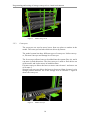
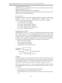
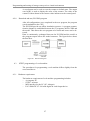
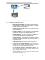
Programming and testing of storage conveyor in a virtual environment PROGRAMMING AND TESTING OF STORAGE CONVEYOR IN A VIRTUAL ENVIRONMENT. Bachelor’s thesis Degree Programme in Automation Engineering Valkeakoski 19th April 2013 Ademola Abdul-Rahman Amida Programming and testing of storage conveyor in a virtual environment ABSTRACT Valkeakoski Degree Programme in Automation Engineering Author Ademola Abdul-Rahman Amida Subject of Bachelor’s thesis Year 2013 Programming and testing of storage conveyor in a virtual environment ABSTRACT This thesis was a developmental project to program and test a storage conveyor model developed by the Research and Development Center of HAMK University of Applied Sciences. The model will be used to facilitate teaching PLC programming. The objective of this thesis was to design a PLC program (with SIEMENS STEP 7) for the control of the model and test out its functionality. Other objectives included the design of a user’s manual for the model, improvement recommendations and identification of bugs in the model. The thesis work was divided into three main sections. The first section deals with the programming of the model using SIEMENS STEP 7. The second part involves the testing of the model and bug identification. The final part describes the design of a user’s manual for the model. In conclusion, a demo program was designed, improvement recommendations were made, and a user manual was developed for the model. Keywords Model, input/output, STEP 7, Radio Frequency Identification (RFID) Pages 35 p. + appendices 20 p. 1 Programming and testing of storage conveyor in a virtual environment LIST OF ABBREVIATIONS CD CPU CU FB FC FBD HMI I/Os IW LAD MPI MRES MW OB PC PLC QW RF RFID S7 SFC STL VE VLE VR - Down Counter Central Processing Unit Up Counter Function Block Function Function Block diagram Human Machine Interface Inputs and Outputs Input Word Ladder Diagram Multiple Point Interface Memory Reset Memory Word Organizational Block Personal Computer Programmable Logic Controller Output Word Radio Frequency Radio Frequency Identification SIEMENS STEP 7 Sequence Function Chart Statement List Virtual Environment Virtual Learning Environment Virtual Reality 2 Programming and testing of storage conveyor in a virtual environment CONTENTS 1 INTRODUCTION ....................................................................................................... 6 2 MODEL AND VIRTUAL ENVIRONMENT ............................................................ 7 2.1 Model .................................................................................................................. 7 2.2 Simulation ........................................................................................................... 7 2.2.1 Benefit of simulation ............................................................................... 8 2.2.2 Barriers of simulation .............................................................................. 9 2.3 Virtual learning ................................................................................................... 9 2.4 Virtual Environment .......................................................................................... 10 2.5 Virtual model..................................................................................................... 10 2.6 Pros and Cons Virtual Environment applications ............................................. 10 2.7 Future of Virtual applications ........................................................................... 11 3 THE MODEL OVERVIEW ...................................................................................... 12 3.1 Benefit of this model ......................................................................................... 12 3.2 Technical description ........................................................................................ 12 3.2.1 Elevators ................................................................................................ 13 3.2.2 Storage levels......................................................................................... 13 3.2.3 Conveyors. ............................................................................................. 14 3.2.4 Proximity sensors .................................................................................. 15 3.2.5 RFID ...................................................................................................... 15 3.2.6 Box Stoppers ......................................................................................... 16 3.3 User Interface .................................................................................................... 17 3.3.1 HMI (Control Panel).............................................................................. 17 3.3.2 Menus .................................................................................................... 18 3.3.3 Key shortcuts ......................................................................................... 18 3.4 Safety................................................................................................................. 18 4 PROGRAMMING WITH SIEMENS (DEMO PROGRAM) ................................... 19 4.1 SIEMENS (STEP 7) .......................................................................................... 19 4.2 Model programming procedures ....................................................................... 19 4.2.1 Model operation..................................................................................... 20 4.2.2 Sequence Function Chart (SFC) ............................................................ 21 4.2.3 Flip-flop chain ....................................................................................... 21 4.2.4 STEP7 .................................................................................................... 22 4.2.5 Program structure .................................................................................. 24 4.2.6 Symbol Editor ........................................................................................ 25 4.2.7 User program creation (Implementation of Blocks) .............................. 25 4.2.8 Download and run (PLCSIM) program ................................................. 27 4.3 STEP7 programming of a real machine ............................................................ 27 4.3.1 Hardware requirement ........................................................................... 27 4.3.2 Real machine programming procedures ................................................ 28 4.4 Safety requirements STEP 7 program. .............................................................. 29 5 MODEL TESTING, IMPROVEMENT AND USER MANUAL ............................ 30 5.1 Model part test ................................................................................................... 30 5.2 Error list............................................................................................................. 30 3 Programming and testing of storage conveyor in a virtual environment 5.3 Model improvement .......................................................................................... 30 5.4 Model user’s manual ......................................................................................... 31 5.4.1 Manual usage ......................................................................................... 31 5.4.2 User requirements .................................................................................. 31 5.4.3 Writing the user’s manual ..................................................................... 31 5.4.4 Access to the user’s manual .................................................................. 31 6 CONCLUSION ......................................................................................................... 32 SOURCES ...................................................................................................................... 33 4 Programming and testing of storage conveyor in a virtual environment Appendix 1 MODEL USER’S MANUAL Appendix 2 SEQUENCE FUNCTION CHART Appendix 3 PROGRAM STRUCTURE Appendix 4 SYMBOL TABLE Appendix 5 STEP 7 PROGRAM 5 Programming and testing of storage conveyor in a virtual environment 1 INTRODUCTION Recent scientific and technological developments have given rise to advancement in computer modeling. Computer modeling applications are used in education, in the medical field, in gaming applications, military training, aviation, astronomy, psychology and engineering. Simulation technologies are widely employed in the area of training and research. Simulations in education are used for both technical and non-technical purposes. Models are sometime used before an existing system is altered, or a new system built, to reduce the chances of failure to meet the specifications and to optimize system performance. Computer model applications are utilized in automation system design. An example of computer modeling is the energy system optimization model used in modern industries for energy optimization and management. The Research and Development Centre (AutoMaint) at HAMK University of Applied Sciences, Valkeakoski unit, was developing a computer model replica of a storage conveyor in a virtual environment which will be used for teaching PLC programming. As a final year student I was given the project as a final thesis with the following objectives. The first objective was to design a demo program with SIEMENS (STEP 7) PLC to automatically control the model in the virtual environment. In addition, test out the model, its features, sensors, elevators, conveyors, stoppers and its control panel. The testing also includes identification of bugs, errors and system malfunction in the model. Recommendations, feedbacks, and improvement suggestions were expected to be given about the model. The second objective was to write a user manual about the functionalities, key shortcuts, controls and operations of the model. The user manual is a technical document which gives assistance to students on the usage of the model. The project will be used to teach student PLC programming, and it is particularly effective since students can operate the model from home and at any time. 6 Programming and testing of storage conveyor in a virtual environment 2 MODEL AND VIRTUAL ENVIRONMENT 2.1 Model A model is an abstraction of a system intended to replicate some properties of that system. The model is similar to but simpler than the system it represents. Models are used in various scientific and engineering systems. Models can be constructed for most systems which may include educational systems, communication system, highway systems, research systems and imaginary systems. Models are generally classified into three according to Tom Schwartz (2012, 2). Namely: Conceptual models: are simplified representations describing physical or social systems to enhance understanding of such systems. Examples are the Big Bang theory, eletrons orbiting the nucleus of an atom. Physical models: are physical copy or representation of a system or object that can be held. Examples are the human body model, the globe. Computer models: are computer generated representation of a system to simulate its behaviour. Examples are mathematical model, weather forecast model, the storage conveyor model. Other examples of models are crowd control model, paper making model and factory process model. Models are widely used in automation engineering to represent different automation systems (machines) which can be used in teaching, training and research. The storage conveyor model is an example of an automation model used to learn PLC programming. Another example is the Automated Highway System model used in traffic control and management. 2.2 Simulation Simulations are used to mimic the operations of a physical or abstract system using a computer software. A simulation is a computerized model of a system which allow the system to be studied and experimented with. Ellafi (2003) stated that simulation models have three major functions: Recreational example is gaming simulations Decision making/Problem solving example mathematical simulations Instructional example virtual classes Khambekar propose that to create a simulation model three elements are needed: 7 Programming and testing of storage conveyor in a virtual environment The parts of the system, The interaction between the parts, The number and nature of inputs (variables). Simulations are widely used for educational purposes. It is used in training and research particularly when it is expensive or dangerous to allow trainees to use real equipments. Example of simulation in education is ‘simSchool’ which is a classroom simulator used by educators to learn classroom management techniques. An example of simulation in engineering is process simulation which is used in oil refineries to give process parameters. 2.2.1 Benefit of simulation Simulations offer the following general benefit (Ellafi 2003): Effective and efficient: Simulations help to create familiarity with skills, programs, systems and process without using the real system or process. Cost effective: Most simulations are cheaper to build compared to the cost of acquiring the real system. Risk free: Simulations allow user to test their skills in real life situations (simulation) without real life consequences. Flexibility: Simulations are easier to modify and manipulate to perform different functions than the real system its imitates. Simulations also offer benefits in education for both teachers and students. Benefit of simulation for students: Simulations are risk free. Students can test simulation systems of real machine without exposure to danger. Students can practice different things without fear of damaging any component or unit in the simulation. Simulations are an effective way to learn. Its create familiarity with systems and processes giving real life experiences. Simulations can be paused, whereas real machines cannot. Pausing allows more time for students to assess what’s going on. Benefit of simulation for teachers (instructors) Simulations are cost effective. They require fewer resources to construct compared to the real equipment. Simulation creates a flexible environment for teachers to transfer their learning materials. Simulations make teaching easier for teachers since learning resource can easily be distributed to students. Most simulations do not pose any safety risk to the students. 8 Programming and testing of storage conveyor in a virtual environment 2.2.2 Barriers of simulation Barriers of simulations include: Simulation does not run exactly as the real system in a controlled environment. Most simulations require the user to have access to a PC to use the simulation. Poorly designed simulations do not break or damage when wrongly used unlike the real systems.. Poorly built simulations do not allow full safety precaution to be experienced by users. A study was carried out at the University of Toronto Canada (2005) to determine the barriers of simulation-based education in the medical field for anesthesiologists. The study examine this issue with patient simulators. The following barriers were discovered: Lack of training opportunities Lack of free time Stressful and intimidating environment Fear of educator’s judgements Fear of peer’s judgements 2.3 Virtual learning A virtual learning environment (VLE) is a software system designed to support teaching and learning. It is a set of teaching and learning tools designed to enhance the learning experience by including computer and the internet in the learning process (Holyoke, 2011). An example of a virtual learning environment is the storage conveyor model which can be used to learn PLC programming. The model has programmable units which can be programmed with any PLC control program. The input and output variables can be manipulated to change the control sequence and additional tasks can be implemented. These flexible possibilities allow the user of the model to learn and acquire more programming skills. Another example of a virtual learning environment in education is the use of web-based applications which create a medium for students and teachers to meet online and exchange ideas such as WebEx which is used for material sharing and web conferencing. E-learning involves the use of technology and electronic channels in education. It is a technologically aided learning and teaching. New technologies are being designed to further develop the use of e-learning applications. An example of e-learning is the Moodle (Modular Object-Oriented Dynamic Learning Environment) which is a learning management system. 9 Programming and testing of storage conveyor in a virtual environment 2.4 Virtual Environment Virtual Environment is a computer-generated, three-dimensional representation of a setting in which the user of the technology perceives themselves to be and within which interaction takes place. (http://dictionary.reference.com/browse/virtual+environment accessed 11.4.2013). A virtual environment is a computer-simulated environment. Virtual environment applications are widely used in the medical field, gaming applications, in military training, aircraft simulators, in astronomy, in psychology, in education and engineering. For example, in a medical training application, a surgeon can practice particular surgical procedures on a virtual patient. In addition to visual images, the surgeon’s major form of interaction with the system is by means of specially-modified versions of his customary instruments that provide realistic haptic feedback sensations as the surgeon manipulates virtual body tissues (Hunter et al 1993). 2.5 Virtual model A virtual model is a model that is made to appear to exist by the use of computer software (http://oald8.oxfordlearnersdictionaries.com/dictionary/virtual accessed 23.2.2013). Virtual models are easier to study and manipulate because of their flexible nature. Virtual model validation techniques include simulating the model under known input conditions and comparing model output with system output (Maria 1997). Examples of virtual technologies are virtual library, virtual storage, virtual classes and virtual machines. 2.6 Pros and Cons Virtual Environment applications Pros of virtual environment according to Ros O’Leary 2013 include: It widens student access on and off campus to learning resources. It is flexible and easy to manipulate. It can be used to create a simulated environment which gives a lifelike experience. Its minimize cost in training and research since a virtual environment can be built with low cost, considering the material cost of building the actual machine. It provides an enabling environment for materials and information to be shared. It is not difficult to use compared to the complex real machine. It enables user to control their own learning 10 Programming and testing of storage conveyor in a virtual environment Cons of virtual environment include: Off campus access to hardware and networks can be problematic for students. It is not a real machine so the user does not get the actual feeling of using a real machine. Most virtual environments can only run on a PC, therefore cannot be used by a user without a PC. 2.7 Future of Virtual applications The future of virtual applications according to Janet Clarey 2012 can be summarised into the following: The future of virtual reality is an augmented reality technology which enhances your perception of reality, it is more of a physical real world environment whose element is augmented by a computer generated layer such as sound, video and graphics. New technology being developed include ’Human less learning’ example is surface computing, Haptic technology (a feeling based technology) More informal learning technology will emerge in the future. Example mobile learning, learning with mobile apps. More virtual classrooms will replace most conventional classroom to minimize cost in the future. . 11 Programming and testing of storage conveyor in a virtual environment 3 THE MODEL OVERVIEW The model is a computer replica of a storage conveyor in a virtual environment. The model is used to store boxes of different colours into different storage levels, and its operation is controlled automatically. The model is an example of an automation model which provide programmable units (actuator) to enhance the learning of PLC programming. A picture of the model is shown in Figure 1. Figure 1 3.1 Model (Storage conveyor) Benefit of this model The following are the benefits of this model. The model can be programmed like a real storage conveyor enabling the user to learn PLC programming. The model can be used without any fear of damaging any machine component. The model is easily accessible to the user once the zip file has been installed. The model is cheaper to install than installing real storage conveyor. The model does not pose any safety risk to an inexperienced user. 3.2 Technical description The model consists of eight belt conveyors, four storage levels, two elevators, four stoppers, twenty nine proximity sensors, RFID, control panel buttons and motors. It also contains the inputs and the output I/O unit which receives and send data in and out of the model. Most input has a Boolean data type. The in12 Programming and testing of storage conveyor in a virtual environment put and output are stated in the program symbol table that will be discussed later in this report. 3.2.1 Elevators The elevators move the boxes between levels from the first level. The elevators are affected by the program outputs which drives the elevators up or down. There are two elevators in the model; Elevator 1 and Elevator 2. Elevator 1 takes the boxes in and elevator 2 takes the boxes out (fetch box). Figure 2 shows the elevators. Figure 2 Model elevator 3.2.2 Storage levels There are four storage levels and each level store a specific box colour. Level 1 is for not identified boxes, Level 2 for blue boxes, Level 3 for green boxes and Level 4 for orange boxes. The boxes move in from the left side of the storage level and move out from the right. Figure 3 shows the storage levels. The blue box is identified by RFID as a 16 bit word 16#0001 Green box is identified by RFID as a 16 bit word 16#0002 Orange box is identified by RFID as a 16 bit word 16#0003 Not identified box is identified by RFID as a 16 bit word 16#0194 13 Programming and testing of storage conveyor in a virtual environment Figure 3 3.2.3 Model storage level Conveyors. The conveyors are used to move boxes from one place to another in the model. The conveyor has belts which are driven by motors. The model system has three different types of conveyors: In/Out conveyor, Elevator conveyor and Storage level conveyor. The In-conveyor allows boxes to be added into the system (Box in), and it can move in both directions. The Out-conveyor is used to fetch boxes out of the model, and it also moves in both directions. Elevator conveyor allows the boxes to move onto elevator 1 and move out of elevator 2. Storage level conveyor allows the boxes to be moved from elevator 1 to its storage position and also out of the storage level to elevator 2. Figure 4 shows the conveyors. Figure 4 Model conveyor 14 Programming and testing of storage conveyor in a virtual environment 3.2.4 Proximity sensors Proximity sensors are used to detect the presence of the box and elevators and its information is used in the control program design. There are about twenty nine proximity sensors in the model. Figure 5 shows the proximity sensors. Figure 5 3.2.5 Model proximity sensor RFID RFID (Radio Frequency Identification) is a wireless non-contact radio frequency identification technology. It is used to track and identify objects at a distance. RFID system is an example of automatic identification systems. Figure 6 shows the components of an RFID. Stephen proposes that an RFID system contains: RFID tag or transponder: is a small device attached to the physical object which stores and sends data to the reader. RFID reader or transceivers: receive data from the RFID tag and respond with some identification information based on its data record. RFID application software. RFID system basic principle of operation (http://www.posright.com/new/how_RFID_work_reader_functions accessed 23.3.2013) is as follows: The RFID reader produces an electromagnetic field. When the RFID tag gets into this field, it receives the radio frequency RF signal emitted by the reader. The RF induces energy into the RFID tag, the RFID tag then sends out information stored in the tag chip to the reader. The RFID reader receives the signal and sends to the information system centre for processing 15 Programming and testing of storage conveyor in a virtual environment Figure 6 RFID Radio Frequency Identification (OMICRON Lab) RFID is used in the model to identify the boxes as they move on the conveyor to determine the level where it will be stored. Figure 7 shows the RFID. Blue box is identified by RFID as a 16 bit word 16#0001 Green box is identified by RFID as a 16 bit word 16#0002 Orange box is identified by RFID as a 16 bit word 16#0003 Not identified box is identified by RFID as a 16 bit word 16#0194 Figure 7 Model RFID sensor 3.2.6 Box Stoppers Stopper is located on each storage level of the model towards the end. It is used to stop and hold the boxes in place to prevent them from falling from the conveyor. Figure 8 shows the box stoppers. 16 Programming and testing of storage conveyor in a virtual environment Figure 8 3.3 Model box stopper User Interface The user interface provides a medium where the user can interface or connect with the model. This enables the user to interact, operate and control the model. The user interface consists of the control panel, the menus, key shortcuts and mouse behaviour. 3.3.1 HMI (Control Panel) The control panel contains control buttons which allow the user to operate and control the model. The control buttons includes the stop and start buttons, the box in and box out buttons for the four different box colours. Figure 9 shows the control panel. Figure 9 Model control panel 17 Programming and testing of storage conveyor in a virtual environment 3.3.2 Menus The menus allow the user to perform various functions. The menu is divided into three: File contains - Reset which can be used to delete all the boxes from the model - Quit which is used to exit or quit the model. View contains - Control was used to open/close the HMI control window - Log contains warnings and debugs information from the model. Help contains - Manual which is accessible from the website - About (Information about the model). 3.3.3 Key shortcuts Key shortcut enables the user to use the keyboard to execute some operations on the model. The key shortcuts include: 3.4 ‘C’ on the keyboard can be used to open/close the control panel window. ‘I’ can be used to on/off the ‘sensor status indicator’. Key 1- 9 on the keyboard can be used to view the model at a different camera angle. Click on the box to ‘camera follow’ the box in the model. Safety The safety of both human, machine and environment is very important. The following are important safety precautions to take before operating the storage conveyor in real life: Ensure that the emergency stop button is functioning correctly. Ensure that the mains were disconnected during the service of the machine. Ensure that personnel are kept away at a reasonable distance to the machine during operation. The machine operating program should be designed to allow the device to be controlled manually in an emergency situation. Implement mechanical or electrical interlocking between automation task to improve safety. Ensure that the machine is serviced periodically to improve safety. 18 Programming and testing of storage conveyor in a virtual environment 4 PROGRAMMING WITH SIEMENS (DEMO PROGRAM) 4.1 SIEMENS (STEP 7) STEP 7 is a programming software solution for solving control problems. Its automation tool is the Simatic Manager. The Simatic Manager is the main tool in STEP 7 (Berger 2005, 49). The complete program of a central processing unit (CPU) consists of the operating system and the user program. The operating system is a fixed part of the program and cannot be changed, but the user program can be changed (Berger 200, 125). The programming languages in STEP 7 are Ladder (LAD), Function block (FBD) and Statement list (STL). The Demo program (user program) was designed with FBD language. The version of STEP 7 used in this project is V5.5 + SP1. S7-PLCSIM user interface enables the user to test and run offline programs without additional hardware. The S7-PLCSIM version used in this project is V5.4 + SP5. S7-PLCSIM software is installed separately but in newer version of S7, this separate installation may not be needed. The S7-PLCSIM communication is integrated into the Simatic Manager and are both interfaced into the model environment so that the model can be controlled. 4.2 Model programming procedures The following procedures were executed in the programming of the model with S7: Design of a program control sequence (see appendix Sequence Function Chart). Design of a program flip-flop chain. Design of a program structure. Creation of a new STEP7 project. Define the symbol table. Creation of a user program Save and download the program Test and diagnose error 19 Programming and testing of storage conveyor in a virtual environment Figure 10 STEP7 programming procedures 4.2.1 Model operation The model is a storage conveyor that is used to store boxes in four different storage level based on the colour of the box. Each storage level can only accommodate two boxes at a particular time. Box in Introduce a box (with the box button) into the in-conveyor and press the start button. RFID identifies the colour of the box to determine the storage level and the in-conveyor moves the box to elevator 1. Elevator 1 moves the box to the desired storage level. The storage level conveyor move right to allow the box to move into the storage level. The box stopper in the storage level keeps the box in place preventing it from falling from the storage level. Box out The box can be taken out by pressing the ’Box out’ button. The box move out through elevator 2. Stop The model can be stopped at any time by pressing the stop button. The operation process is automatic. See appendix 2 for the model control SFC. 20 Programming and testing of storage conveyor in a virtual environment Counters The storage level sensors left and right are used to count the boxes moving in and out of the storage conveyor. The sensors are integrated into an up and down counter. When the storage level is full, no additional box can be added to that level. A reset button can be used to reset the counter. 4.2.2 Sequence Function Chart (SFC) An SFC describes the step by step flow of the control process. It is also called sequence control which is widely used in automation. It is identical to the flow diagram in computer programming. The control function is divided into two. Namely: States or Steps – States are where events are driven. States can take a long or short time. Example the conveyor moves right. Transition condition – Transition conditions are conditions that must be met (true) before a change of state. Transition points are event monitoring points. Example sensor inputs. States and transitions are alternated in SFC. There are three types of variables in the SFC (Sequence Function Chart). In this program, they are represented as: Inputs are represented by input bits States are represented by memory bits Outputs are represented by output bits The states is where action are driven (output). A state may contain one or more outputs. The SFC of this program can be seen in the appendix 2. Figure 11 shows an example of an SFC. Figure 11 An example of SFC 4.2.3 Flip-flop chain The Flip-Flop chain is a type of sequence control logic used in programming . The logic principle is that if all the transition state (T1) is true, the previous state is reset R and the next state is set S. There are two main states, namely: Reset state means to reset the state to value 0 (stop running) Set state means to set the state to value 1 (start running). 21 Programming and testing of storage conveyor in a virtual environment Figure 12 Shows how SFC is converted to FBD Figure 13 Conversion to Flip-Flop chain 4.2.4 STEP7 The user program was designed in the Simatic Manager which is an automation tool in STEP 7. ‘Simatic Manager Wizard: New project’ was opened by clicking on the Simatic Manager icon on the desktop. The CPU contains the central control processor which executes the operating systems and the user program, assign module parameters and and transmits user data. All CPU modules are equipped with an MPI interface for the connection to the programming device, operator interface systems or other SIMATIC stations (Berger 2006, 38). The CPU name was selected on the wizard dialog box as shown below. The MPI address has a default value of 2. 22 Programming and testing of storage conveyor in a virtual environment Figure 14 STEP7 CPU name The organization blocks (OBs) are the interfaces between operating system and user programs. The organization blocks (OBs) are part of the user program and are called and processed by the operating system when certain events occur (Berger 2006, 125). The organization blocks (OBs) are divided into priority classes which determine the sequence of the program processing (‘mutual interruptability’) when several events occur. The processing priority can be specified within the framework permitted by the particular CPU (Berger 2006, 125). The organization blocks OBs and the programming language (FBD is used in this program) was selected as shown below. Figure 15 STEP7 block name and language 23 Programming and testing of storage conveyor in a virtual environment The Simatic Manager window gives access to the following functions: Project file used to store data and programs. Project library Download icon used to download program to the programmable logic controller. Online/offline button used to switch from online to offline view of the program and vice versa. Configure network used to configure PROFIBUS, Ethernet and MPI networks. Simulation on/off (PLCSIM) used to run and test programs. The Simatic Manager window is shown below. OB1 is the master program block and it appears in the window by default. Other blocks (FB, FC, and OBs) can be added into the program. Figure 16 STEP7 OB1 appears in the window. 4.2.5 Program structure The program structure shows the call hierarchy structure. The program structure of the user program can be seen in appendix 3. In this program, the organisational block OB1 is the master controller program. Figure below shows the program structure. 24 Programming and testing of storage conveyor in a virtual environment Figure 17 The program structure 4.2.6 Symbol Editor Symbol editor is used to assign symbols to signals and other variables. The symbol table contains variable definitions which are used in the program and the model. The variables include inputs, outputs, functions, memory bit and memory word. It shows symbol names, addresses, data type and comments. A symbol can only be used once on the symbol table. Easy to remember words can be attached to addresses. See Figure 19. Figure 18 Symbol Table 4.2.7 User program creation (Implementation of Blocks) The user program was created with FBD language and stored as blocks. The program is divided into different parts to help in reading and understanding. A block is a section of the user program which is defined by its function, structure or its intended purpose. (Berger 2005, 96). The different block type used in this program includes OBs and FCs. 25 Programming and testing of storage conveyor in a virtual environment Organizational block (OBs) These blocks serve as an interface between the operating system and user programs. (Berger 2005, 96). OBs used in this program are OB1 and OB100. OB1 is the master program block. OB1 also includes all the function calls. OB100 is the complete restart block. Function (FCs) Functions are used to program frequently recurring or complex automation functions. They can be parameterized. (Berger 2005, 97). The FCs used in this program are FC1, FC2, FC3, FC4, FC5 and FC6. FC1 in the ‘Box in’ program, FC2 is the ‘Box out’ program, FC3 is the ‘Output control’ program, FC4 is the ‘Pressured stop’ program, FC5 is the ‘Identify colour’ program and FC6 in the ‘Counter’ program. Implementation of RFID The RFID plate on the ‘in – conveyor’ identifies the box colour by reading the colour code on the box as hexadecimal code displaced as input word IW7. Each colour has a 16 bit hexadecimal code in the memory of the program which is compared with the RFID IW7 input using the comparator block. The comparator compares the two values. If the value matches a box colour code, the output is copied as a memory bit colour code. Blue colour code is 0001H Green colour code is 0002H Orange colour code is 0003H Not identified colour code is 0194H Figure 19 RFID implementation block Counters Up/Down counter is used to monitor the state of the model storage levels if it’s full or empty. The storage level can only store two boxes at a time. A rising edge at input CU (up count) counts the box going into the model and input CD (down count) counts the box going out of the conveyor. The counter output value is a 16 bit memory word (MW) which is copied into a comparator. The output value is compared with zero and two a itemized below: If the value is zero, then the storage level is empty, If output value is two, the storage level is full. If the output value is one, the storage level can only accept one more box. 26 Programming and testing of storage conveyor in a virtual environment A reset button can be used to reset the counter to default state. The output word (QW) is used to display the value of the counter. The value of the counters is then shown in the counter value indicator on the control panel. 4.2.8 Download and run (PLCSIM) program After all configurations were completed in the user program, the program was downloaded to the CPU. The PLCSIM provide an offline simulation resource. A program communication channel is established between the S7 programs, the PLCSIM and the model. This allows the user program to be tested and errors can be detected. Data is continuously exchanged between the PLCSIM and the model as the program output affects the model actuators. The figure below shows the data flow. Figure 20 Data flow diagram 4.3 STEP7 programming of a real machine The procedures for programming a real machine differs slightly from the ones stated above. 4.3.1 Hardware requirement The hardware requirement of real machine programming includes: A computer PC STEP 7 software MPI-interface for the PC (PC- Adapter) PLC SIMATIC S7-300 with digital In- and Output device. 27 Programming and testing of storage conveyor in a virtual environment Figure 21 S7 Hardware requirement (SIEMENS) 4.3.2 Real machine programming procedures Design the program structure: The program structure should be designed beforehand. This allows the automation task to be examined thoroughly before the real programming. Create a new STEP 7 project: A new STEP 7 project should be created as described earlier. Configure a station: This is the specification of the programmable controller that is desired to be used. Example SIMATIC 300. Configure hardware: This involves specifying the modules to be used for the automation solution in a configuration table. Configure networks: Create subnets for your automation networks, set network connection properties and other connections required for the networked stations. Symbol table creation: this is same as described in section 4.2.6. Creation of user program and definitions: The user program is created using any of the available programming language. The program created is linked to a module and stored as blocks or files. Save and download program to programmable controller: After the user program programming tasks are complete, download the program to the programmable controller. Test and diagnose error: test user program by displaying variable values from user program or CPU. 28 Programming and testing of storage conveyor in a virtual environment 4.4 Monitor operation and diagnose hardware: This is done by displaying online information about the module. A diagnostic buffer or stack contents can be used to determine the cause of the error. Archive the program: Always remember to keep good documentation of your user programs. Safety requirements STEP 7 program. The program should be designed to allow the device to be controlled manually in an emergency situation. Implement mechanical or electrical interlocking between automation task to improve safety. Emergency stop (break switch) should be implemented to shut down the operation of the entire device. 29 Programming and testing of storage conveyor in a virtual environment 5 MODEL TESTING, IMPROVEMENT AND USER MANUAL Model testing involves the testing of the model with the intent of finding faults and errors (bugs). The different parts of the model and the data exchange between the model and the PLCSIM were tested in this project. 5.1 Model part test The model part tested include proximity sensors, IN/OUT conveyor, storage levels, box stoppers, control panel and elevators. The proximity sensor in storage level 4 left (I 3.5) was not working properly. All other sensors are working properly. The IN/OUT conveyor are both functioning properly. The elevators are also working properly. The control panel buttons are working properly. 5.2 Error list Bugs are errors or faults found in systems or software that produces unexpected results and system malfunction. The bug found in the system include: The model did not open after it had been minimized. 5.3 Model improvement This section addresses several improvement recommendations to the model. The improvement recommendations include: Reduction of the control panel buttons to allow a broader view of the model. Introduction of a movement direction indicator of the motor. Adding a sensor light indicator Adding a storage level movement indicator Adding a reset button that can be used to drive all the actuators to their initial state. Adding an emergency stop button. Adding a counter value display. 30 Programming and testing of storage conveyor in a virtual environment 5.4 Model user’s manual User’s manuals are written guides in either a paper copy or an electronic document format that provide instructions on how to do or use something. They educate users about the product’s features and how to use them (http://www.wikihow.com/Create-a-User-Manual accessed 15.4.2013). 5.4.1 Manual usage The user’s manual was designed to provide instructions to users on how to use the model. It provides step by step guidance on the use of the model. The user’s manual can be used from any location as long as the model is accessible. 5.4.2 User requirements The requirements of the user are as follows: The user must have general knowledge about a computer. The user must have basic STEP 7 programming skills. The user must be able to operate in a virtual environment. 5.4.3 Writing the user’s manual The following steps were considered when writing the user’s manual: The user of the manual: Some reasonable assumptions where made about the user based on the user’s manual requirements for example, the skills level of the user. The format of the user’s manual: The manual is simple and not too technical to understand. Pictures and texts were used to explain the procedures in details. Model features: The model features were well explained and broken down into smaller parts in the user’s manual. Model operation: The operational procedures of the model were clearly stated. 5.4.4 Access to the user’s manual The user’s manual is available here in appendix 1. It is also available at the web link provided. 31 Programming and testing of storage conveyor in a virtual environment 6 CONCLUSION A PLC program was successfully designed with STEP7 to automatically control the model. The model units were working properly and the bug detected was reported. A user’s manual was successfully designed to help the users of the model A major challenge was to understand the objectives and to implement the project. Other challenges encountered included: The design of the user program sequence The integration of the RFID into the user program The implementation of the counters The model is too complex for inexperience PLC students to understand at once. The model should be broken down into smaller units to teaching PLC programming. The model can be used for industrial purposes when planning new systems or improving old ones. It can also be used in training operators on how to use the system. The model project was a laudable one because of the opportunities it will provide for students to learn PLC programming skills. It is recommended that more work should be done on the compatibility of the model with the VMware View Client (virtual desktop) so that students without PLC software on their PC can use the model from home. It is also recommended that Industrial Process Models should be constructed to aid the teaching of process measurement and control. This model will indicate temperature, pressure, and flow measurement and control. It may also include DCS programming. This is an important part of automation technology. 32 Programming and testing of storage conveyor in a virtual environment SOURCES Berger, H. 2005. Automating with STEP 7 in LAD and FBD. Erlangen: Publicis Corporate Publishing. Berger, H. 2006. Automating with SIMATIC. Erlangen: Publicis Corporate Publishing Ellafi, M. A. 2003. Simulation in Education. Accessed 9th March 2013. http://projects.edte.utwente.nl/pi/sim/AliEllafi.html Federley, S., Jussila, J., Mattila, J., Horelli, J., Väänänen, M. 2010. Using simulation models to improve the planning-delivery chain. Kaunas: 5th International Conference on Electrical and Control Technologies . Georges, L. S., Viren, N. N., Stanley, J. H., Pamela, J. M., 2005. Barriers to use of simulation-based education. Accessed 9th March 2013. http://www.politicalcollectors.com/Thesis/Barriers%20to%20use%20of% 20simulation-based%20education.pdf Hayford, V. 2012. Canning Machinery with Siemens Simatic PLC-control, Programming, Test Programming Holyoke, M. 2011. Accessed 23rd Feb. http://whatis.techtarget.com/definition/0,,sid9_gci866691,00.html http://dictionary.reference.com/browse/virtual+environment 11th April 2013). 2013. (accessed http://www.omicron-lab.com/application-notes-31052011/rfid-resonancefrequency-measurement.html (accessed 23rd March 2013) http://www.posright.com/new/how_RFID_work_reader_functions cessed 23rd March 2013). http://www.engineersgarage.com/insight/how-rfid-tag-works 23rd March 2013). (ac- (accessed http://www.automation.siemens.com/mcms/sce/en/advanced_training/train ing_material/download_training_material/a_basics_step7_programming/D ocuments/a03_startup.pdf (accessed 23rd March 2013) http://www.automation.siemens.com/doconweb/pdf/SINUMERIK_SINA MICS_02_2012_E/S7P.pdf?p=1 (accessed 23rd March 2013) http://www.systems-thinking.org/modsim/modsim.htm Feb. 2013) (accessed 23rd http://oald8.oxfordlearnersdictionaries.com/dictionary/virtual 23rd Feb. 2013) (accessed http://www.cs.sunysb.edu/~cse529/chap1.pdf (accessed 23rd Feb. 2013) 33 Programming and testing of storage conveyor in a virtual environment http://www.wikihow.com/Create-a-User-Manual (accessed 15th 2013) April. Hunter, I.W., T.D. Doukoglou, S.R. Lafontaine, P.G. Charette, L.A. Jones, M.A. Sagar, G.D. Mallinson, and P.J.Hunter. 1993. ‘A Teleoperated Microsurgical Robot and Associated Virtual Environment for Eye Surgery.’ pp 265-280 Janet, C. 2012. Creating a Learning Environment for the Modern-Mobile worker. Accessed 9th March 2013. http://www.safaribooksonline.com/webcast/2012-11-08-190000/safaribooks-online-webcast-creating-learning-environment-modern-mobile# Khambekar, A. What is a simulation model? Accessed 23rd Feb. 2013. http://www.wisegeek.com/what-is-a-simulation-model.htm Maria, A. 1997. Introduction to modeling and simulation. Accessed 23rd Feb. 2013. http://www.inf.utfsm.cl/~hallende/download/Simul-22002/Introduction_to_Modeling_and_Simulation.pdf Overstreet, C. M. 1982. Model Specification and Analysis for Discrete Event Simulation p.44 O’Leary, R. Accessed 23rd Feb. 2013. http://www.bioscience.heacademy.ac.uk/ftp/Resources/gc/elearn2.pdf Pohjasto, H. 2010. Automation Lecture series: Automation Department HAMK University of Applied Sciences. Schwartz, T. 2012. Which type of model will be most effective in teaching about moon phases? Accessed 23rd March 2013 http://www.slideshare.net/tschwartz37/physical-vs-computer-models Smith, R. 1998. Encyclopedia of Computer Science, Simulation Article. Accessed 23rd Feb. 2013. http://www.modelbenders.com/encyclopedia/encyclopedia.html Weis, S. Principles and Applications. Accessed 23rd March 2013. http://www.eecs.harvard.edu/cs199r/readings/rfid-article.pdf 34 Programming and testing of storage conveyor in a virtual environment Appendix 1 35 Programming and testing of storage conveyor in a virtual environment Appendix 2 SEQUENCE FUNCTION CHART Figure 22 Box in Sequence Function Chart 36 Programming and testing of storage conveyor in a virtual environment Figure 2 Box out Sequential Function Chart 37 Programming and testing of storage conveyor in a virtual environment Appendix 3 PROGRAM STRUCTURE 38 Programming and testing of storage conveyor in a virtual environment Appendix 4 SYMBOL TABLE 39 Programming and testing of storage conveyor in a virtual environment Appendix 5 STEP 7 PROGRAMS 40