1
Digital Video Recorder
User Manual
AD-800
AD-808
1
Disclaimer
This manual is designed to assist customers in the use of the Digital Video Recorder
(DVR). No warranty or representation, either expressed or implied, is made with respect
to the contents of this documentation, its quality, performance, merchantability, or fitness
for a particular purpose. Information presented in this documentation has been carefully
checked for reliability; however, no responsibility is assumed for inaccuracies. The
information contained in this documentation is subject to change without notice.
In no event will our company be liable for direct, indirect, special, incidental, or
consequential damages arising out of the use or inability to use this product or
documentation, even if advised of the possibility of such damages.
Video and Audio surveillance may be regulated by laws that vary from state to state and
country to country. Check the laws in your local region before using the DVR for
surveillance purposes.
We are not liable for damages resulting from corrupted or lost data due to a mistaken
operation or malfunction of the Digital Video Recorder, the software, the hard drives,
personal computers, peripheral devices, or unapproved/unsupported devices.
This equipment has been tested and found to comply with the limits for a Class A
computing device pursuant to Subpart B of Part 15 of FCC rules, which are designed to
provide reasonable protection against such interference when operated in a commercial
environment.
2
Table of Contents
I - Important Safety Information
6
II - Important maintenance Information
8
III - Overview
9
IV - Specifications
10
V - Front Panel
12
VI - Real Panel of AD-800 and AD-808
14
VII - Remote Control
17
VIII - Device Controlled with Mouse
19
Chapter 1 – Main Screen and main Menu
20
1.1 Power On
20
1.2 Turning Off
20
1.3 Main Screen
21
1.4 Login
24
1.5 Main Menu
25
Chapter 2 – Digital Video Recording Configurations
27
2.1 Schedule Recording
29
2.2 Video file Playback
33
2.2.1 Playback File Search
2.3 Video File Backup
Chapter 3 – Alarm Configurations
35
40
43
3.1 Motion Detection
44
3.2 Video Blind
48
3.3 Video Loss
51
3.4 Alarm Input
54
3.5 Alarm Output
56
3.6 Hard Disk (HDD) Error
57
3
Chapter 4 – System Configurations
59
4.1 General
61
4.2 Encode
63
4.3 Network
65
4.3.1 Internet Connection for Remote Monitoring
4.4 Net Service
4.4.1 Dynamic Domain Name System (DDNS) Setting
66
67
68
4.5 Graphic User Interface (GUI) Display
80
4.6 Pan Tilt Zoom (PTZ) Configuration
82
4.7 On Screen Video Display Sequence
84
Chapter 5 – Advanced Configurations
86
5.1 Hard Disk (HDD) Management
87
5.2 Account
88
5.2.1 Modify User
89
5.2.2 Modify Group
91
5.2.3 Modify Password
93
5.2.4 Add User
94
5.2.5 Add Group
96
5.2.6 Delete User
98
5.2.7 Delete Group
99
5.3 On-line Viewer
100
5.4 Display Adjustment
101
5.5 Auto Maintenance
102
5.6 Restore Factory Default
103
5.7 Update
105
5.8 Miscellaneous Setting
106
4
Chapter 6 – Info
107
6.1 Hard Disk (HDD) Info
108
6.2 Bite per Second (BPS)
110
6.3 LOG Information
111
6.4 Version of Software
112
Chapter 7 – Logout
113
7.1 Logout
113
7.2 Reboot
113
5
I
Important Safety Information
Stop using the equipment immediately if you detect condensation. Continued use may
damage the equipment. Remove the power cord and power supply from the power
outlet and wait until the moisture evaporates completely before resuming use.
Avoid strong magnetic fields. Never place the equipment in close proximity to electric
motors or other equipment generating strong electromagnetic fields. Exposures to
strong magnetic fields may cause malfunctions or corrupt image data.
Avoid condensation related problems. Moving the equipment rapidly between hot and
cold environments may cause condensation (water droplets) to form on its external and
internal surfaces.
Do not cover the ventilation opening or slots on the outer casing. To prevent the device
from overheating, provide at least two inches of air space around the vent and the slots.
Do not operate the equipment beyond its specified temperature, humidity or power
source ratings. Do not use the device in an extreme environment where there is high
temperature or high humidity. Use the device at temperatures within +0°C ~ +40°C
(32°F ~ 104°F) and humidity below 90 %. The normal operating power needed for this
device is DC 12V 50/60Hz.
Do not drop metallic objects into the device. This could permanently damage the
equipment. Immediately turn the power off or unplug the power cord and power supply
from the power outlet if this happens. Contact a qualified service personnel authorized
by your equipment distributor.
Do not attempt to disassemble or alter any part of the equipment that is not expressed
in this guide. Disassembly or alteration of this device may result in electrical shock.
Stop operating the equipment if a heavy object is dropped on the device and/or if the
casing is damaged. Also, do not strike or shake the device. Failure to do so may result
in fire or electrical shock. Immediately turn the equipment’s power off and unplug the
power cord and power supply from the power outlet if this happens.
Do not allow the equipment to come into contact with, or become immersed in, water or
other liquids. Do not allow liquids to enter the interior. The equipment is not waterproof.
If the exterior comes into contact with liquids or salty air, wipe it dry with a soft,
absorbent cloth. In the event that the water or other foreign substances enter the interior,
immediately turn the equipment off and unplug the power cord and power supply from
the power outlet. Continued use of the equipment may result in fire or electrical shock.
Do not use substances containing alcohol, benzene, thinners or other flammable
substances to clean or maintain the equipment. The use of these substances may
6
cause fire or electrical shock. Use a dry cloth and clean it on a regular basis to wipe
away the dust and dirt that collects on the device. In dusty, humid or greasy
environments, the dust that collects around the ventilation areas on the outer casing
may become saturated with humidity and short-circuit, leading to fire.
Do not cut, damage, alter, or place heavy items on the power cord or power supply. Any
of these actions may cause an electrical short circuit, which may lead to fire or electrical
shock.
Do not handle the equipment if your hands are wet. Handling it with wet hands may lead
to electrical shock. When unplugging the power cord, make sure that you hold the solid
portion of the plug. Pulling on the flexible portion of the power cord may damage or
expose the wire and insulation, creating the potential for fire or electrical shock.
This equipment should be operated only with the supplied power cord and power supply.
The voltage of the power source must be verified before using. Use only the
recommended power accessories. If the device has not been used for a long period of
time, disconnect the power source. Use of power sources not recommended for this
equipment may lead to overheating, distortion of the equipment, fire, electrical shock, or
other hazards.
Do not attempt to disassemble, alter or apply heat to the batteries. Do not place the
batteries near heat sources or expose to direct flame or heat. Neither should you
immerse them in water. Such exposure may damage the batteries and lead to the
leakage of corrosive liquids, fire, electrical shock, or explosion. If the eyes or skin
contact these substances, immediately flush with water and seek medical assistance
from a medical professional.
Do not use the supplied power cord and power supply with any other products. There is
a risk of fire and other hazards when the supplied power cord and power supply are
used with other products.
Do not attempt to disassemble, alter, or repair the equipment, It may cause fire,
electrical shock, explosion or serious injury. Please contact your equipment distributor
for services.
7
II
Important Maintenance Information
For your benefit, please follow these steps and you will increase the working lifetime of
the equipment.
Please read the manual and follow the warnings and instructions listed in it.
Do not block any ventilation openings. Ensure sufficient ventilation around the
equipment. The openings on the equipment are provided for ventilation and to ensure
reliable operation of
the equipment. The openings should never be blocked by placing the product on a bed,
sofa, rug, or similar surfaces. Equipment should never be placed near or over a radiator
or heat source, or in a built-in enclosure such as a bookcase or rack unless proper
ventilation is provided.
Make sure the equipment is turned off before it is unplugged. Disconnect the power if it
has not been in use for a long period of time.
Do not power off the equipment during normal operation. Please follow the correct
procedures for shutting down the equipment to avoid damage of hard disk:
(1) Stop the recording first.
(2) Select the “logout” button on the menu screen to logout.
(3) Select the “Shutdown” button on the menu screen to logout.
(4) Turn off the power switch then disconnect the power cord.
(5) Wait for 30 seconds before restarting or moving the equipment.
Do not use liquid cleaners or aerosol cleaners when cleaning the device. Use only a dry
cloth for cleaning.
Do not use the equipment in a dusty or dirty work area. The ventilation openings should
be cleaned at regular intervals.
Do not operate your equipment near a source of heat or in direct sunlight. Do not place
the equipment near water or in extremely humid conditions.
Do not use the equipment near water or other liquids, or in rainy/moist situations. If
liquid gets into your equipment, turn it off and take it to your dealer for inspection.
Do not use the equipment in a potentially flammable work area.
Do not place this product on an unstable cart, stand, tripod, bracket, or table. Do not
drop the unit or subject the unit to major shocks or jolts. The product may not operate
normally.
Do not exert pressure on the equipment such as stacking objects on it.
8
III
Overview
This high quality Digital Video Recorder (DVR) is designed to use advanced H.264
digital technology with an embedded Linux operating system. This outstanding DVR
provides high quality video and low error coding ratio performance to ensure the
reliability of this device in security and surveillance applications. This device has been
meticulously developed to be a capable and dependable video surveillance device. The
auxiliary features of this device are listed below.
DVR Feature
Advanced H.264 video compression
ADPCM audio compression format
Dual video out (BNC/ VGA) for CRT and LCD monitor connection
Pentaplex operation (Record/ Playback/ Backup/ Remote viewing at the same
time)
Multiple recording modes (Manual/ Schedule/ Motion)
Multiple alarm notification buzzers (Video loss/ Video Blind/ Motion/ HDD failure)
Remote monitoring via web browser or mobile phone
Mobile phone viewing (Android/ Blackberry/ iPhone /iPad / Nokia-Symbian/
Windows Mobile)
Include wireless remote control and USB mouse for easy operation and setup
Manage and view up to 64 cameras simultaneously with enterprise grade Central
Management Software (CMS)
9
IV
DVR Specifications
Model
Operating system
System resources
Operation interface
Menu display
AD-800
AD-808
Embedded LINUX
Multi-channel real-time recording, playback, multi-channel
network, USB backup
16-bit true color graphical menu interface and mouse
support
1/4 screen
1/4/8 screen
Video standards
PAL(625line,50f/s); NTSC(525 line,60f/s)
Video Recording
D1:PAL 1f/s-25f/s NTSC 1f/s-30f/s
Video compress
standard
Recording FPS
Motion detection
Audio compression
H.264 Mainprofile
100/120fps
Zones:396(22*18)detection zones,Sensitivity:1-6(6 is
highest) Trigger recording, PTZ movement, tour, alarm,
email, snapshot & FTP
G711A
Bidirectional talk
Support
Recording mode
Manual>alarm>Dynamic Detection>Time
Playback
One channel or multi-channel playback (AD-800:4 channel
max, AD-808:8 channel synchronized playback)
Search mode
HDD consumption
Time/ Event search
Audio:28.8MB per hour/ Video:25~450MB per hour
Video storage
Hard disk, network
Backup mode
Network download/USB/SATA HDD
Video input
4 channel BNC,1.0Vp-p,75Ω
8 channel BNC,1.0Vp-p,75Ω
Video output
1 channel BNC,1.0Vp-p,75Ω and 1 channel VGA
Audio input
Audio output
1 channel
8 channel
1channel RCA,200-3000mV,5KΩ
Network interface
PTZ control
USB interface
Hard disk
Power supply
Power consumption
RJ45 10M/100M
No
Yes
3 port
1 SATA port/ Support up to 2TB (2000GB)
12V/4A
<10W(without hard disk)
Operating temperature
0℃-+55℃
Operating humidity
10%-90%
Atmosphere pressure
Net Weight/pcs
86kpa-106kpa
4.4lb
10
G.W./pcs
Dimension
5.5lb
13" x 10" x 2.4"
11
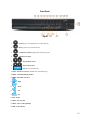
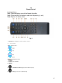
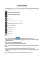
Front Panel
Fig. A
1.
– Previous (go to the beginning of the recorded video file)
2.
– Next (go to the next recorded video file)
3.
– Slow Motion Forward (toggle between 4 different speeds)
4.
– Fast Motion Forward
5.
/
– Play Backward / Pause
6.
\
– Play Forward / Pause
7.
– Search for recorded video files
8. PTZ/8 – Pan Tilt Zoom Control (available for 8 channel DVR only)
9. INFO/9 – Hard Disk (HDD) Information
10. MENU – Enter Menu Selections
11.
– Right
12.
– Down
13.
– Left
14.
– Up
15. ESC – Escape
16. SHIFT – Function shift
17. REC/0 – Start recording manually
18. PWR – Power indicator
12
19. HDD – Hard Disk (HDD) Indicator
20. IR – Infrared sensor for remote control
21. USB – USB mouse port
13
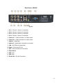
Rear Panel of AD-800
Fig. B.1
1. CH 1 – Channel 1 (camera 1) connection
2. CH 2 – Channel 2 (camera 2) connection
3. CH 3 – Channel 3 (camera 3) connection
4. CH 4 – Channel 4 (camera 4) connection
5. Video out 1 – Video connection 1 to video monitor
6. Video out 2 – Video connection 2 to video monitor
7. Audio In – Audio input
8. Audio out – Audio output, connection to sound box
9. LAN – RJ45 Ethernet network port
10. Power – Power Input DC12V
11. VGA – VGA connection to VGA monitor
12. Power Switch
13. USB – port
14. USB – port
15. RS-485 B A – RS-485 Connections
14
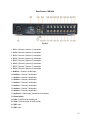
Rear Panel of AD-808
Fig. B.2
1. CH 1 – Channel 1 (camera 1) connection
2. CH 2 – Channel 2 (camera 2) connection
3. CH 3 – Channel 3 (camera 3) connection
4. CH 4 – Channel 4 (camera 4) connection
5. CH 5 – Channel 5 (camera 5) connection
6. CH 6 – Channel 6 (camera 6) connection
7. CH 7 – Channel 7 (camera 7) connection
8. CH 8 – Channel 8 (camera 8) connection
9. Audio In – Channel 1 Audio input
10. Audio In – Channel 2 Audio input
11. Audio In – Channel 3 Audio input
12. Audio In – Channel 4 Audio input
13. Audio In – Channel 5 Audio input
14. Audio In – Channel 6 Audio input
15. Audio In – Channel 7 Audio input
16. Audio In – Channel 8 Audio input
17. Audio out – Audio output, connection to sound box
18. Power Switch
19. LAN – RJ45 Ethernet network port
20. VGA – VGA connection to VGA monitor
21. USB – port
22. USB – port
15
23. RS-485 B A – RS-485 Connections
24. Power – Power Input DC12V
16
VII
Remote Control
Loading batteries:
Step1: Open the battery cover of the Remote Controller
Step2: Place two AAA size batteries and check the polarity (+ and -)
Step3: Replace the battery cover
Fig. C
1. Digital Buttons – Digit input or channel (camera) selections
2. -/-- – Time and Date
3. ESC – Escape/cancel
4.
– Right
5.
– Left
6.
– Up
7.
– Down
8. MENU – Enter Menu Selections
9.
– FULL SCREEN
10. SEARCH
11.
– Slow Motion Forward (toggle between 4 different speeds)
12.
– Next (go to the next recorded video file)
17
13.
– Previous (go to the beginning of the recorded video file)
14.
– Play Forward / Pause
15.
– Play Backward / Pause
16.
– Fast Motion Forward
17.
– Short cut to <Record Mode>
18. FN – Function short cut to [PTZ Control] and [Color Setting]
19. ADD – Remote Address
18
VIII
Device Controlled with Mouse
Connecting the Mouse
This DVR supports USB mouse through the ports on the front and rear panel.
☞Note: If the mouse doesn't work, check the following steps:
1. Make sure the mouse is plugged properly into the USB mouse port.
2. Change to a different mouse port.
3. Change the physical mouse.
Using the Mouse
In Main Screen:
Double-click the left button on one of the camera displays to switch to full screen display.
Double-click again to return to the previous screen display.
In Menu Setting:
Right click to show the pop-up options and short cuts. Click the left button to select the
option.
For entering a value, click on the parameter entering area. An input window will appear
then
click to enter the value.
19
Chapter 1
Main Screen and main Menu
1.1 Power On
Before you power on the equipment, please check all of the connections are properly connected.
Step1: Plug in the power cord to the socket on the rear panel (refer to 10 on Fig. B).
Step 2: Switch on the power switch on real panel
Step 3: Power Indicator will be on and the system will start loading
Step 4: System will generate a beep after system loading complete
Step 5: The System Login Menu will display (refer to Fig. 1)
☞Note: The DVR will automatically recover to its previous state when the device is restarted from
the power off.
1.2 Turning Off
Before turning off the hard switch or disconnecting the power source to turn the system off, it is
strongly recommended that the user applies these following steps to have the best protection for
equipment and user applications:
A. Please confirm that the all of the hard disk (HDD) activities are properly stopped, which includes
“recording”, “playback”, “backup”.
B. Please confirm that all of the user and remote monitoring activities and applications are properly
stopped and logout.
There are two steps to turn off the DVR; the soft switch and the hard switch. It is strongly
recommended that the user applies these two steps sequentially to have the best protection for
equipment.
Step1 - Soft Switch Off: select [Main menu] then select [Logout] then click on [Shutdown] to turn the
system off (refer to Fig. 35.).
Step 2 – Hard Switch Off: flip the power switch (refer to 18 on Fig. B) to turn the system off.
☞Note:
The cooling fan will remain on when the system is turned off by soft switch. The cooling fan
will turn off when the system is turned off by the hard switch.
This equipment is designed for the long term security surveillance applications. Frequently
disconnecting the power source is not recommended.
20
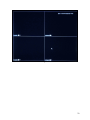
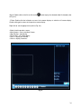
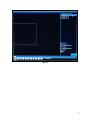
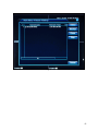
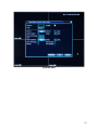
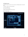
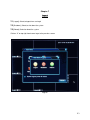
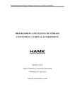
1.3 Main Screen
All of the channels (cameras) are displayed (refer to Fig. 1) on the Main Screen. Double-click on any
camera display to switch to a full screen display. Double-click again to return to the previous screen
display.
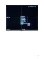
Step 1: Right-click on the mouse to show the pop-up options (refer to Fig. 1.1).
Step 2: Select the <Main Menu> tab.
Step 3: The login screen will display (refer to Fig. 2).
☞Note:
Remote Control
Press the MENU button on remote control to show the Main Menu (refer to Fig. 1).
Front Panel Control
Press the MENU button on front panel to show the Main Menu (refer to Fig. 1).
☞Note:
Remote Control
Press the
button on remote control to have a full screen display.
Front Panel Control
Press the Up button on front panel to have a full screen display. Left and Right to change the
channel (camera). Down button to return to the previous regular display.
21
Fig. 1
22
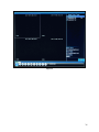
Fig. 1.1
23
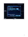
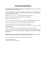
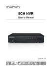
1.4 Login
Please enter the User Name and the Password for system login (refer to Fig. 2).
There are two default users:
(1) “admin” Default with no password.
“admin” is the supervisor with full access.
(2) “guest” Default with no password.
“guest” is a user with limited access.
☞Note: For security and user protection issues, please contact your distributor for assistant if the
login password is forgotten or lost.
After the system login:
Step 1: Right-click on the mouse to show the pop-up options (refer to Fig. 1).
Step 2: Select the <Main Menu> tab.
Step 3: The Main Menu will display (refer to Fig. 3)
Fig. 2
24
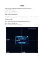
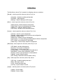
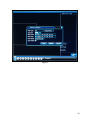
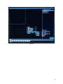
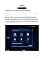
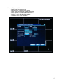
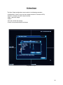
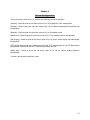
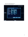
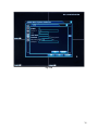
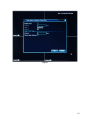
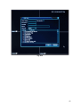
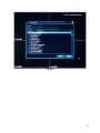
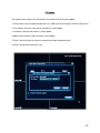
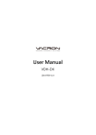
1.5 Main Menu
The Main Menu (refer to Fig. 3) contains the following sub menu selections:
[Record] - select to go to the sub menu (refer to Fig. 4) for
[Schedule] - Schedule recording configuration
[PlayBack] - Video playback
[Backup] - Video file backup to USB storage
[Alarm] - select to go to the sub menu (refer to Fig. 8) for
[Motion Detect] - Motion detection configuration
[Video Blind] - Camera view blockage alert setting
[Video Loss] - Video loss detection setting
[HDD Error] - Hard drive error notification setting
[System] - select to go to the sub menu (refer to Fig. 13) for
[Genera]l - General system configuration
[Encode] - Video recording quality and frame rate configuration
[Network] - Network setup
[NetService] - Network services configuration
[GUI Display] - On screen display and video output resolution configuration
[PTZ Config] – not available on AD-600 model
[Video Seq.] - Camera display sequence configuration
[Advanced] - select to go to the sub menu (refer to Fig. 21) for
[HDD Mgmt]- Hard disk Management
[Account] - User account management
[Online Viewer] - Online viewer status
[Display Adjust] - On screen display position adjustment
[Auto Maint] - System auto maintenance setting
[Restore] - Reset system parameters to factory default
[Update] - System software update
[Misc Setting] - Audio Alarm Remote control setting
[Info] - select to go to the sub menu (refer to Fig. 30) for
[HDD Info] - Hard disk capacity and status
[BPS] - Bitrate per second
[LOG] - System log information
[Version] - System software version
[Logout] - select to go to the sub menu (refer to Fig. 34) for
[Logout] - System logout
[Reboot] – System reboot
25
Fig. 3
26
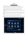
Chapter 2
Digital Video Recording Configurations
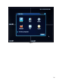
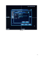
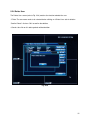
Record
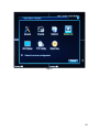
The Record menu (refer to Fig. 4) contains the following sub menu selections:
[Schedule] - Select to go to the sub menu (refer to Fig. 5) for schedule recording configuration
[PlayBack] - Select to go to the sub menu (refer to Fig. 6) for video playback
[Backup] - Select to go to the sub menu (refer to Fig. 7) for video file backup to USB storage
Record Mode Screen: right click on Main Screen (refer to Fig. 1) to have the popup options (refer to
Fig. 1.1) then select the
Record Mode (refer to Fig. 5.2) to have the following options:
Mode
All
Channel
(camera)
1
Channel
(camera)
2
Channel
(camera)
3
Channel
(camera)
4
Schedule
Manual
Stop
Schedule: select the corresponding channel (camera) to start the video recording by schedule
Manual: select the corresponding channel (camera) to start the video recording manually
Stop: select the corresponding channel (camera) to stop the video recording
<OK> tab: exit with the changes
<Cancel> tab: go back without the changes
27
Fig. 4
28
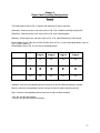
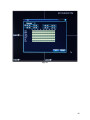
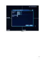
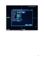
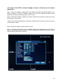
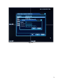
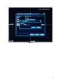
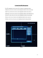
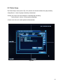
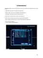
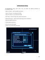
2.1 Schedule Recording
The Schedule screen (refer to Fig. 5) contains the following parameters for schedule recording
configuration:
<Channel>: select the corresponding channel (camera) for schedule recording configuration
<Redundancy>: not available on AD-800 and AD-808
<Length in Minutes>: setup the length of each recording file
<PreRecord in Seconds>: start the video recording before the beginning of scheduled recording periods
<Mode>: select the following mode for the corresponding channel (camera)
<Schedule>
: select to start the video recording by schedule
<Manual>
: select to start the video recording manually
<Stop>
: select to stop the video recording
The following schedules need to be configured if the schedule recording is selected for the
corresponding channel (camera):
<Week>: select the day for scheduled recording setup
<Period 1>: set up the time interval of recording for Period 1
<Period 2>: set up the time interval of recording for Period 2
<Period 3>: set up the time interval of recording for Period 3
<Period 4>: set up the time interval of recording for Period 4
<Regular>
: click on this
to select the corresponding period for regular video recording
<Detect>
: click on this
to select the corresponding period for detection triggered recording
when camera detection is triggered
☞Note: Please refer to Motion Detect, Video Blind, and Video Loss under the Main Menu>Alarm for
more information.
<Alarm>
: click on this
alarm input is triggered.
to select the corresponding period for alarm triggered recording when
☞Note: not available on AD-600
<OK> tab: exit with the changes
<Cancel> tab: go back without the changes
Select on [Advanced] tab (refer to Fig. 5.1) for
<Back>: back to previous screen
<Main Screen>: short cut to Main Screen
29
<Copy>: copy the content of schedule parameters
<Paste>: paste the copied schedule parameters
<Default>: reset to the default parameters
<HDD Mgmt>: short cut to HDD Mgmt
Fig. 5
30
Fig. 5.1
31
Fig. 5.2
32
2.2 Video File PlayBack
The PlayBack screen (refer to Fig. 6) contains a Search icon and the following control buttons for
video files playback:
– Start to play the selected video file forward
– Start to play the selected video file backward
– Pause
– Stop Playing
– Slow Motion Forward (toggle between 4 different speeds)
– Fast Motion Forward (toggle between 4 different speeds)
– Previous video picture frame
– Next video picture frame
– Previous video file
– Next video file
– Repeat Playing
– Full Screen
Step 1: Select the “Search” icon
to search the playback files (refer to Fig. 6.1).
☞Note: The hard disk that contains the recorded video files must be set to read/write or read only
for video playback state.
Step 2: Set the search conditions before searching.
☞Note: Please confirm that the Sync Mode has been enabled
Step 3: Click the [Search] tab to start the search or [Play] tab to start the search and play the first
found file.
Step 4: The found video files will be listed on the right side of the screen (refer to Fig. 6.2).
☞Note:
H = Manual recorded file, R. Schedule recorded file, M = Motion/blind/loss detection
recorded file
Step 5: Click on the file to see the Starting Time and Ending Time (refer to Fig. 6.2).
33
Step 6: Double click on the file or click on the
to Fig. 6.3).
button to play the selected video file forward (refer
☞Note: Double-click the left button on one of the camera displays to switch to full screen display.
Double-click again to return to the previous screen display.
Right click to see the popup menu (refer to Fig. 6.4).
<Back>: back to previous screen
<Main Screen>: short cut to Main Screen
<Stop Playing>: stop playing
<Full Screen>: full screen display
<View 1>: display one camera
<View 4>: display 4 cameras
Fig. 6
34
2.2.1
PlayBack File Search
The Search Condition screen (refer to Fig. 6.1) contains the following search conditions for playback:
<File Type>: Select the following file types to be searched for playback
<All>: Select all types
<Alarm>: Select the recorded video files which were triggered by alarm
<MD> (Motion Detection): Select the recorded video files which were triggered
by camera motion detection
<Alarm/MD>: Select both alarm and motion detection triggered video files
<Manual>: Manually recorded video files
<General>: General scheduled video files
<Read/Write> / <Backup Device>: Select the file source from a Read/Write HDD or an external
backup device
<Channel>: Select the channel (camera) for play back search
<Start Time>: Select the beginning of time interval for play back search
<End Time>: Select the ending of time interval for play back search
<Play Mode>:
<Skip Decode>:
<Average Decode>:
<Full Decode>:
Step 1: Please confirm that the Sync Mode has been enabled.
Step 2: Set the search conditions for search.
Step 3: User has two options to start the Search and play:
Option A: Click on the [Search] tab to start the search. The found video files will be listed on the right
side of the PlayBack screen (refer to Fig. 6.2). Follow Step 5 under the PlayBack section to play the
video files(refer to Fig. 6.3).
Option B: Click on [Play] tab to start the search and play the first found video file.
<Cancel> tab: go back to previous screen
35
Fig. 6.1
36
Fig. 6.2
37
Fig. 6.3
38
Fig. 6.4
39
2.3 Video File Backup
The Backup screen (refer to Fig. 7) contains the following functions:
[Detect] tab: click on this tab to detect the available USB backup devices
: click on this
to select the USB backup device
[Backup] tab: click on this tab to go to the Backup File Search Condition screen (refer to Fig. 7.1) for
video file searching and backup
Video File Search Condition screen (refer to Fig. 7.1)
<Type>: select the type of video file from the following options
All: All types of video files
Alarm: Alarm triggered video files
MD: Motion Detection triggered video files
Alarm/MD: Alarm and Motion Detection triggered video files
Manual: Manually recorded video files
General: General scheduled video files
<Channel>: select the channel (camera)
<Start Time>: select the starting time
<End Time>: select the ending time
<Add> tab: click on this tab to start the file search
☞Note: The found video files will be listed. User can select/deselect the files from the list to
backup.
<Remove> tab: click on this tab to remove the found video files from the list
<Backup Format>: select the file format to be stored on USB device
<Start> tab: click on this tab to start the file backup to the USB device
<Cancel> tab: click on this tab to go back to previous screen
[Erase] tab: click on this tab to re-format the USB device
[Stop] tab: click on this tab to stop the backup
<Cancel> tab: click on this tab to go back to previous screen
40
Fig. 7
41
Fig. 7.1
42
Chapter 3
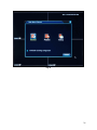
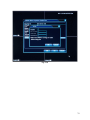
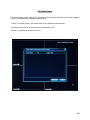
Alarm Configurations
The Alarm menu (refer to Fig. 8) contains the following sub menu selections:
[Motion Detect] - Select to go to the sub menu (refer to Fig. 9) for motion detection configuration
[Video Blind] - Select to go to the sub menu (refer to Fig. 10) for camera view blockage alert setting
[Video Loss] - Select to go to the sub menu (refer to Fig. 11) for video loss detection setting
[Alarm Input] - Select to go to the sub menu (refer to Fig. Alarm Input) for alarm input setting
[Alarm Output] – Select to go to the sub menu (refer to Fig. Alarm Output) for alarm output setting
[HDD Error] - Select to go to the sub menu (refer to Fig. 12) for hard drive error notification setting
<Cancel> tab: go back to previous screen
Fig. 8
43
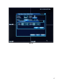
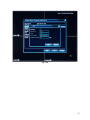
3.1 Motion Detect
The Motion Detection screen (refer to Fig. 9) contains the following parameters for motion detection
configuration:
<Channel>: select the corresponding channel (camera) for the motion detection setup
<Enable>
: click on this
to enable the motion detection
<Sensitivity>: select the motion detection sensitivity
<Region Set> tab: click on to switch to full screen for motion detection region setting
☞Note: Click on a square to active the motion detection region. Click on the square again to deactive the motion detection region. Right click then select <Back> to go back to the Motion Detect
menu
<Period Set> tab: click on the “Set “tab to configure the time interval of each day to activate the
motion detection (refer to Fig. 9.1)
☞Note: Right click then select <Back> to go back to the Motion Detect menu
<Interval>: time interval between two adjacent detected motions
<Record Channel>: select the corresponding channel to start recording when the motion detection is
triggered
<Tour>: select the channel (camera) for sequential display when the corresponding motion detection
is triggered
<PTZ Activation Set> tab: click on “Set” tab to configure the PTZ cameras (refer to Fig. 9.2)
CAM 1:
None
Preset
Tour
Pattern
{0}
<OK>: exit with the changes
<Cancel>: go back without changes
<Delay>:
<Show Message>:
<Send Email>: select to enable the email alert when the motion detection is triggered
<Buzzer>: select to enable buzzer alert when the motion detection is triggered
<FTP upload>: select to enable FTP file upload when the motion detection is triggered
<OK> tab: exit with the changes
<Cancel> tab: go back without the changes
44
Select on [Advanced] tab for
<Back>: back to previous screen
<Main Screen>: short cut to Main Screen
<Copy>: copy the content of schedule parameters
<Paste>: paste the copied schedule parameters
<Default>: reset to the default parameters
<Schedule>: short cut to Schedule
Fig. 9
45
Fig. 9.1
46
Fig. 9.2
47
3.2 Video Blind
The Video Blind screen (refer to Fig. 10) contains the following parameters for video blockage
configuration:
<Channel>: select the corresponding channel (camera) for the video blockage alert setup
<Enable>: select to enable the video blockage alert
<Sensitivity>: select the video blockage alert sensitivity
<Period Set> tab: click on the “Set“ tab to configure the time interval of each day to activate the
video blockage alert (refer to Fig. 9.1)
☞Note: Right click then select <Back> to go back to the Video Blind menu
<Record Channel>: select the corresponding channel to start recording when the video blockage
alert is triggered
<Tour>: select the channel (camera) for sequential display when the corresponding video blockage
is triggered
<PTZ Activation Set> tab: click on “Set” tab to configure the PTZ (refer to Fig. 10.1)
CAM 1:
None
Preset
Tour
Pattern
{0}
<OK>: exit with the changes
<Cancel>: go back without changes
<Delay>:
<Show Message>:
<Send Email>: select to enable the email alert when the video blockage alert is triggered
<Buzzer>: select to enable buzzer alert when the video blockage alert is triggered
<FTP upload>: select to enable FTP file upload when the video blockage alert is triggered
<OK> tab: exit with the changes
<Cancel> tab: go back without the changes
Select on [Advanced] tab for
<Back>: back to previous screen
<Main Screen>: short cut to Main Screen
<Copy>: copy the content of schedule parameters
<Paste>: paste the copied schedule parameters
<Default>: reset to the default parameters
<Schedule>: short cut to Schedule
48
Fig. 10
49
Fig. 10.1
50
3.3 Video Loss
The Video Loss configuration screen (refer to Fig. 11) contains the following parameters for video
loss configuration:
<Channel>: select the corresponding channel (camera) for the video loss alert setup
<Enable>
: click on this
to enable the video loss alert
<Sensitivity>: select the video loss alert sensitivity
<Period Set> tab: click on the “Set “ tab to configure the time interval of each day to activate the
video loss alert (refer to Fig. 9.1)
☞Note: Right click then select <back> to go back to the video Loss menu
<Record Channel>: select the corresponding channel to start recording when the video loss alert is
triggered
<Tour>: select the channel (camera) for sequential display when the corresponding video loss is
triggered
<PTZ Activation Set> tab: click on “Set” tab to configure the PTZ cameras (refer to Fig. 11.1)
CAM 1:
None
Preset
Tour
Pattern
<OK>: exit with the changes
<Cancel>: go back without changes
<Delay>:
<Show Message>:
<Send Email>: select to enable the email alert when the video loss alert is triggered
<Buzzer>: select to enable buzzer alert when the video loss alert is triggered
<FTP upload>: select to enable FTP file upload when the video loss alert is triggered
<OK> tab: exit with the changes
<Cancel> tab: go back without the changes
Select on [Advanced] tab for
<Back>: back to previous screen
<Main Screen>: short cut to Main Screen
<Copy>: copy the content of schedule parameters
<Paste>: paste the copied schedule parameters
<Default>: reset to the default parameters
<Schedule>: short cut to Schedule
51
Fig. 11
52
Fig. 11.1
53
3.4 Alarm Input
The Alarm Input configuration screen contains the following parameters:
<Alarm In>: select the corresponding alarm channel for the alarm input setup
<Enable>: select to enable the alarm input
<Period Set> tab: click on the “Set “ tab to configure the time interval of each day to activate the
alarm input alert
Note: Right click then select <back> to go back to the alarm input menu
<Interval>: the interval time between the two adjacent alarms
<Alarm Output>: select the alarm output when the alarm input alert is triggered (there is only one
alarm output channel for 4/8 channel DVR)
<Delay>: enter the delay in seconds to generate the alarm output when
the alarm input
alert is triggered
<Record Channel>: select the corresponding channel to start recording when the alarm input alert is
triggered
<Tour>:
<PTZ Activation Set> tab: click on “Set” tab to configure the PTZ cameras
CAM 1:
None
Preset
Tour
Pattern
{0}
<OK>: exit with the changes
<Cancel>: go back without changes
<Delay>:
<Show Message>:
<Send Email>: select to enable the email alert when the alarm input alert is triggered
<Buzzer>: select to enable buzzer alert when the alarm input alert is triggered
<FTP upload>: select to enable FTP file upload when the alarm input alert is triggered
<OK>: exit with the changes
<Cancel>: go back without the changes
Select on [Advanced] tab for
<Back>: back to previous screen
<Main Screen>: short cut to Main Screen
<Copy>: copy the content of schedule parameters
<Paste>: paste the copied schedule parameters
<Default>: reset to the default parameters
<HDD Mgmt>: short cut to HDD Mgmt
54
Fig. Alarm Input
55
3.5 Alarm Output
The Alarm Output configuration screen contains the following parameters:
<Configuration>: (there is only one alarm output channel for 4/8 channel DVR)
<Manual>: turning on the alarm output manually
<Stop>: stop alarm output
<Status>:
<OK> tab: exit with the changes
<Cancel> tab: go back without the changes
Fig. Alarm Output
56
3.6 Hard Disk (HDD) Error
The HDD Error configuration screen (refer to Fig. 12) contains the following parameters for hard
drive (HDD) error configuration:
<Event Type>: No Disk
<Enable>: click on to enable the No Disk error alert
<Show Message>: show message when the No Disk error is detected
<Buzzer>: enable the buzzer alert when the No Disk error is detected
<Event Type>: Disk Error
<Enable>: click on to enable the Disk Error alert
<Show Message>: show message when the Disk Error is detected
<Buzzer>: enable the buzzer alert when the Disk Error is detected
<Event Type>: Disk Full
<Enable>: click on to enable the Disk Full alert
<Less Than %>: enter the percent of available space
<Show Message>: show message when the Disk Full condition is detected
<Buzzer>: enable the buzzer alert when the Disk Full condition is detected
<OK> tab: exit with the changes
<Cancel> tab: go back without the changes
57
Fig. 12
58
Chapter 4
System Configurations
The System menu (refer to Fig. 13) contains the following sub menu selections:
[General] - Select to go to the sub menu (refer to Fig. 14) for general system configuration
[Encode] - Select to go to the sub menu (refer to Fig. 15) for video recording quality and frame rate
configuration
[Network] - Select to go to the sub menu (refer to Fig. 16) for network setup
[NetService] - Select to go to the sub menu (refer to Fig. 17) for network services configuration
[GUI Display] - Select to go to the sub menu (refer to Fig. 18) for on screen display and video output
configuration
[PTZ Config]: Select to go to the sub menu (refer to Fig. PTZ Configuration) for Pan Tilt Zoom device
configuration. Please also refer to PTZ device manufactory manual.
[Video Seq.] - Select to go to the sub menu (refer to Fig. 20) for camera display sequence
configuration
<Cancel> tab: go back to previous screen
59
Fig. 13
60
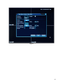
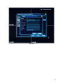
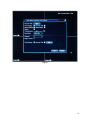
4.1 General
The General screen (refer to Fig. 14) contains the following parameters for general configuration:
<System Time>: select to setup the system time and date
<Date Format>: select the date format
<DST>: select to enable the Daylight Saving Time (DST) calendar period setup
<Date Separator>: select the date separator
<Time Format>: select the time format
<Language>: select the language
<HDD Full>: select the action taken when Hard Disk (HDD) is full
☞Note: Over write is recommended
<DVR No.>: enter the DVR number for multiple DVR identification
<Video Standard>: select the video standard from NTSC or PAL
☞Note: Cameras purchased in U.S.A are NTSC format.
Please confirm the video standard of the
cameras matches the video standard setting of the DVR.
NTSC, named for the National Television System Committee, is the analog television system that is
used in most of North America, most of South America (except Brazil, Argentina, Uruguay, and
French Guiana), Burma, South Korea, Taiwan, Japan, the Philippines, and some Pacific island
nations and territories.
PAL, named for the Phase Alternating Line, is an analogue television colour encoding system used
in broadcasting television systems in many european countries.
<Auto Logout>: enter the time period for auto logout
☞Note: Set to 0 minutes to disable the auto logout
<Machine Name>: enter the DVR name for identification
<OK> tab: exit with the changes
<Cancel> tab: go back without the changes
61
Fig. 14
62
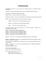
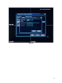
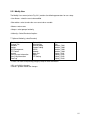
4.2 Encode
The Encode configuration screen (refer to Fig. 15) contains the parameters for video streaming
configuration. The parameters on the left column are the relative setup for the remote monitoring
over the internet/network. The parameters on the right column are the relative setup for the remote
mobile device monitoring.
Parameters Default Setting Table
Main Video Streaming
Channel
Compression
Resolution
Frame Rate (FPS)
Bite rate Type
Quality
Bit Rate(Kb/S)
I Frame Interval
Video/Audio
1
H.264
CIF(352x240)
25
VBR
Good
437
2
[V]
[ ]
Video Enable
Audio Enable
Remote Mobile Device Video
Streaming
Extra Stream
QCIF(176x120)
25
VBR
General
164
2
[ ]
Video Enable
[ ]
Audio Enable
<Channel>: select the corresponding channel (camera) for the Encode setup
<Compression>: ☞Note: H.264 is recommended
<Resolution>: select the video recording resolution from the following options
CIF (352x240), DI (704x480), HDI (704x240), QCIF (176x120)
<Frame Rate (FPS)>: select the Frame Rate (Frames Per Second) from the list
<Bite rate Type>: select the bite rate type from CBR or VBR
☞Note: CBR short for Constant Bite Rate. VBR short for variable Bite Rate
<Quality>: Select the video recording quality from the list
<Bit Rate(Kb/S)>: Bit Rate is fixed by the resolution setting
☞Note: Kb/S stands for Kilobit per second
<I Frame Interval>:
<Video/Audio>: select to enable the video and audio to corresponding data streaming
<OK> tab: exit with the changes
<Cancel> tab: go back without the changes
Select on [Advanced] tab for
<Back>: back to previous screen
<Main Screen>: short cut to Main Screen
<Copy>: copy the content of schedule parameters
63
<Paste>: paste the copied schedule parameters
<Default>: reset to the default parameters
Fig. 15
64
4.3 Network
The Network screen (refer to Fig. 16) contains the following parameters for the network configuration:
<Net Card>:
DHCP Enable
<IP Address>: enter the IP address of this DVR
☞Note: Default 192.168.1.10
<Subnet Mask>: enter the subnet mask
☞Note: Default 255.255.255.0
<Gateway>: enter the gateway
☞Note: Default 192.168.1.1
Generally, the default gateway is the router IP address if this DVR connects to internet through a
router
<Primary DNS>: enter the primary DNS
☞Note:
Generally, the default DNS is the router’s IP address if this DVR connects to internet
through a router
<Secondary DNS>: enter the secondary DNS
<Media Port>: This Media Port (TCP) number is the port for video streaming
☞Note: The default value is 34567. This video steam port needs to be forwarded on the router or
virtual server for video streaming.
<HTTP Port>: The HTTP port number is the port for IE browser accessing.
☞Note: The default value is 80. This port needs to be forwarded on the router or virtual server for
remote monitoring. If the port value is changed, user needs to add the port number when typing the
IP address into the IE browser address bar .i.e.
set HTTP port to 88, IP address: http://192.168.0.50, user needs to enter that address as
http://192.168.0.50:88 to IE browser.
<HS Download>:
<Transfer Policy>:
<Adaptive>:
<Quality Preferred>:
<Fluency Preferred>:
<OK> tab: exit with the changes
<Cancel> tab: go back without the changes
65
4.3.1 Connect the DVR to internet through a router or virtual server for remote
monitoring:
Step 1: Enter the IP address, Subnet Mask, and Gateway. Generally, the default gateway is the
router’s IP address The DVR’s IP address need to be in the same segment with router. Please
enable DHCP in both the DVR and router If DHCP is used.
Step 2; Forward the IP address, Media Port number, and HTTP Port number in Virtual Server setup
on the router or virtual server.
☞Note: IP and Port Forwarding may be different in different routers and server. Please check your
router manual for details.
Step 3: Disable the firewall on router and virtual server.
Step 4: For dynamic IP internet service, the DDNS need to be configured either on the DVR or
router for remote monitoring. Please refer to DDNS configuration in NetService section for utilizing
Dynamic Domain Name Service (DDNS).
Fig. 16
66
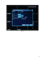
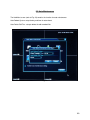
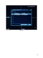
4.4 Net Service
The NetService screen (Refer to Fig. 17) contains the following parameters for the internet service
configuration:
☞Note: Please contact your Internet Service Provider (ISP) for more information.
☞Note: click on the <Set> tab to edit the highlighted parameter or double click on the parameter
line for editing.
<PPPOE>: (refer to Fig. 17.1)
<Enable>: enable/disable the PPPoE internet service login
<User Name>: enter the login user name
<Password>: enter the login password
<IP Address>: enter the IP address which is provided by the Internet Service Provider.
☞Note: The PPPoE needs to be enabled and the User Name, Password, and IP address of ISP
need to be entered if PPPoE login is employed on the DVR. Please contact your Internet Service
Provider (ISP) for more information
<Set> tab: click on this <Set> tab to edit the highlighted parameter
<OK>: exit with the changes
<Cancel>: go back without the changes
<NTP>: (refer to Fig. 17.2)
<Enable>: enable the NTP internet service
<Server IP>: enter the NTP server IP
<Port>: enter the port
<Time Zone>: Select the Time Zone by Greenwich Mean Time (GMT)
<Update Period>: enter the update period
<OK>: exit with the changes
<Cancel>: go back without the changes
☞Note: Table of Time Zones in the USA
Time Zones in the USA
Eastern Standard Time (EST)
Central Standard Time (CST)
Mountain Standard Time (MST)
Pacific Standard Time (PST)
GMT
GMT -5
GMT -6
GMT -7
GMT -8
Daylight Saving Time
GMT - 4
GMT - 5
GMT - 6
GMT - 7
<EMAIL>: (refer to Fig. 17.3):
<Enable>: enable/disable the email notification
<SMTP Server>: enter the name of the SMTP mail server
<Port>: enter the port
<Need SSL>: enable/disable the SSL (Secure Sockets Layer)
<User Name>: enter the user name
<Password>: enter the password
<Sender>: enter the sender
67
<Receiver>: enter the receiver
<Tile>: enter the email message
<OK>: exit with the changes
<Cancel>: go back without the changes
<IP Filter>: (refer to Fig. 17.4)
<Enable>: enable the IP filter
<Restricted Type>: select the type of list to edit: “Blacklist” or “Whitelist”
. . . : enter the IP to be added onto the list
<Add> Tab: click on to add the above entered IPs to the list
<Delete> tab: click on to delete the selected IPs from the list
<OK>: exit with the changes
<Cancel>: go back without the changes
☞Note:
“Blacklist” – the list of restricted IPs
“WhiteList” – the list of allowed IPs.
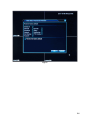
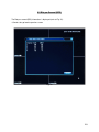
4.4.1 Dynamic Domain Name System (DDNS) setting
<DDNS>: Dynamic Domain Name System (DDNS) setting for internet remote viewing (refer to Fig.
17.5)
☞Note: For the following DDNS parameter settings, user needs to have one active account from
DYNDNS for valid parameter values. Please visit dyndns.org to obtain an account if the user does
not have one.
<DDNS Type>: DYNDNS service is recommended
<Enable>: enable the DDNS
<Domain Name>: enter the domain name (example - <your domain name>.dyndns.org)
<User Name>: enter the user name
<Password>: enter the password
<OK>: exit with the changes
<Cancel>: go back without the changes
<FTP>: (refer to Fig. 17.6)
<Enable>: enable the FTP
<Server IP>: enter the FTP server IP
<Port>: enter the FTP port number
<User Name>: enter the user name
<Password>: enter the password
<Anonymous>: select to be anonymous
<Max File Length>: enter the maximum file length in Min.
<DirName>: enter the Dir name
<OK>: exit with the changes
<Cancel>: go back without the changes
<AlarmServer>: (refer to Fig. 17.7)
<Protocol Type>: only the type of GENERAL is available from the selection
<Enable>: enable the alarm server
68
<Server Name>: enter the alarm server name
<Port>: enter the port number of alarm server
<Alarm report>: select to enable the alarm report
<Log report>: select to enable the log report
<OK>: exit with the changes
<Cancel>: go back without the changes
<Mobile Monitor>: (refer to Fig. 17.8) default port number is 34599
<Enable>: enable the mobile monitor
<Port>: enter the port number for mobile monitoring
<OK>: exit with the changes
<Cancel>: go back without the changes
☞Note: This
Mobile Monitor setting is required for mobile device remote viewing such as smartphones. Please refer to the mobile device manual, instructions of the APPs (Applications), and
mobile service provider for more information.
<UPNP>: (refer to Fig. 17.9)
<Enable>: enable the UPNP
<HTTP Port>:
<TCP Port>:
<Mobile Port>:
☞Note: UPNP on the router needs to be on
<OK>: click on to exit and save the changes
<Cancel>: go back without the changes
69
Fig. 17
70
Fig. 17.1
71
Fig. 17.2
72
Fig. 17.3
73
Fig. 17.4
74
Fig. 17.5
75
Fig. 17.6
76
Fig. 17.7
77
Fig. 17.8
78
Fig. 17.9
79
4.5 Graphic User Interface (GUI) Display
The Graphic User Interface (GUI) Display screen (refer to Fig. 18) contains the following parameters
for on screen user interface display configuration:
<Channel Title> Set tab: click on this Set tab to enter the channel (camera) title
<Time Display>: select to enable the Time display
<Channel Title>: select to enable the Channel (camera) Title display
<Record Status>: select to enable the Record Status display
<Alarm Status>: select to enable the Alarm Status display
<Deflick>: select to enable the Deflick
<Transparency>: adjust the transparency of text display
<Resolution>: select the resolution of VGA display
Region Cover is a special feature which allows user to define coverage regions of certain areas
from the on screen display for privacy and security issues.
<Channel>: select the channel (camera) to be defined for the coverage regions
<Region Cover>
: click on this
to enable the Region Cover feature.
☞Note: User can define up to 4 coverage regions for each channel (camera) by clicking on the
following tabs.
<1> <2> <3> <4> tab: click on the tabs to enable the coverage regions
☞Note: the tabs must be selected in order to be defined
<Set> tab: click on this Set tab to switch to full screen to define the enabled coverage regions
☞Note: drag each coverage region on the full screen display to the preferred position. Right click
then select <back> to go back to the previous screen.
<Time Display>
: click on this
to enable time display
<Channel Title>
: click on this
to enable channel (camera) title display
<Set> tab: click on this Set tab to switch to full screen to position the Time Display and Channel
(camera) Title display on screen
☞Note: Drag on the Time and Channel Title to the preferred position. Right click then select <back>
to go back to the previous screen.
<OK>: exit with the changes
<Cancel>: go back without the changes
80
Fig. 18
81
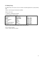
4.6 PTZ Configuration
The PTZ screen (Refer to Fig. PTZ Configuration) contains the following parameters for Pan Tilt
Zoom (PTZ) control configuration:
Parameters Default Table
PTZ Device
Channel
Protocol
Address
Baudrate
Data Bits
Data Bits
Stop Bits
Parity
Monitors
RS485 Device
1
PELCOD
1
9600
8
1
None
0
0
NONE
1
9600
8
1
None
PTZ Device
<Channel>: select the corresponding channel (camera) for Pan Tilt Zoom (PTZ) control configuration
Note: A PTZ camera needs to be connected to the corresponding channel
<Protocol>: select the PTZ control protocol from the available list
<Address>: enter the address
<Baudrate>: select the baud rate from 1200, 2400, 4800, 9600, 19200, 38400, 57600, or 115200
<Data Bits>: select the data bits from 5, 6, 7, or 8
<Stop Bits>: select the stop bits from 1 or 2
<Parity>: select the parity check from None, Odd, Even, Mark, or Space
<Monitors>:
RS485 Device
<Protocol>: select the PTZ control protocol from the available list
<Address>: enter the address
<Baudrate>: select the baud rate from 1200, 2400, 4800, 9600, 19200, 38400, 57600, or 115200
<Data Bits>: select the data bits from 5, 6, 7, or 8
<Stop Bits>: select the stop bits from 1 or 2
<Parity>: select the parity check from None, Odd, Even, Mark, or Space
82
<OK>: exit with the changes
<Cancel>: go back without the changes
(fig. PTZ Configuration)
83
4.7 On Screen Video Display Sequence
The Video Sequence screen (refer to Fig. 20) contains the following parameters for channel (camera)
on screen sequential display configuration:
☞Note: Video Sequence is a feature used to define the sequence of on screen display for each
channel (camera). User can select the channels (cameras) to be displayed on screen and define the
time interval between each display.
<Enable Tour>
: click on this
to enable the video sequential display feature
<Interval>: enter the time interval between each channel (camera) display
☞Note: minimum interval is 5 seconds
<View 1>: select the channel (camera) or channels (cameras) to be added to the display sequence
<View 4>: select 4 channel (4 camera) display to be added to the display sequence
Alarm Tour Type: configure the display sequence when alarm is triggered
☞Note:
Please refer to the Tour selection of Motion Detect, Video Blind, and Video Loss under
Alarm Configurations
<Interval>: >: enter the interval for the alarm triggered channel (camera) display sequence
☞Note: This parameter is corresponding to the alarm triggered channel (camera) display sequence.
Please refer to the Tour selection of Motion Detect, Video Blind, and Video Loss under Alarm
Configurations
<Return after finished> : click on this
to enable the return function to go back to the regular
display (View 1/View 4) after the alarm triggered sequence (Tour) is complete
☞Note: This function is not related to the enabled video sequential display
<OK>: exit with the changes
<Cancel>: go back without the changes
84
Fig. 20
85
Chapter 5
Advanced Configurations
The Advance menu (refer to Fig. 21) contains the following sub menu selections:
[HDD Mgmt] - Select to go to the sub menu (refer to Fig. 22) for hard disk (HDD) management
[Account] - Select to go to the sub menu (refer to Fig. 23) for user account management
[Online Viewer] - Select to go to the sub menu (refer to Fig. 24) for online viewer status
[Display Adj] - Select to go to the sub menu (refer to Fig. 25) for on screen display position
adjustment
[Auto Maint] - Select to go to the sub menu (refer to Fig. 26) for system auto maintenance setting
[Restore] - Select to go to the sub menu (refer to Fig. 27) for reset system parameters to factory
default
[Update] - Select to go to the sub menu (refer to Fig. 28) for system firmware update
[Misc Setting.] - Select to go to the sub menu (refer to Fig. 29) for audio/ alarm/ remote control
setting
Fig. 21
86
5.1 Hard disk (HDD) Management
The HDD management screen (refer to Fig. 22) contains the following functions:
<Read/write> tab: click on this tab to set the highlighted hard disk to be read and write
<Read Only> tab: click on this tab to set the highlighted hard disk to be read only
<Redundant> tab: click on this tab to set the highlighted hard disk to be Redundant only
<Format Disk> tab: click on this tab to set the highlighted hard disk to be formatted
<Recover> tab: click on this tab to set the highlighted hard disk to be recovered
<Partition> tab: click on this tab to set the highlighted hard disk to be partitioned
Fig. 22
87
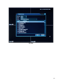
5.2 Account
The Account screen (refer to Fig. 23) contains the following functions:
<Modify User> tab: click on this tab to modify the user information and authority (refer to Fig. 23.1)
<Modify Group> tab: click on this tab to modify a group of authority (refer to Fig. 23.2)
<Modify Pwd> tab: click on this tab to modify the user password (refer to Fig. 23.3)
<Add User> tab: click on this tab to add new user (refer to Fig. 23.4)
<Add Group> tab: click on this tab to add new group of authority (refer to Fig. 23.5)
<Delete User> tab: click on this tab to delete the user (refer to Fig. 23.6)
<Delete Group> tab: click on this tab to delete the group of authority (refer to Fig. 23.7)
Fig. 23
88
5.2.1 Modify User
The Modify User screen (refer to Fig. 23.1) contains the following parameters for user setup:
<User Name>: select the user to be modified
<Reuseable>: select to make the user name to be re-useable
<Memo>: enter memo
<Group>: select group of authority
<Authority>: Select/Deselect all options
Option of Authority (select/Deselect)
Shutdown the device
Channel Title
Schedule
Backup
HDD Management
PTZ Control
Account
Query System Information
Query Log Information
Clear Log
System Update
Auto Maintain
General coding
Encode Coding
RS232
Network
Alarm Set
Motion
PTZ Setting
Restore
Talk
Monitor_CH01
Monitor_CH02
Monitor_CH03
Monitor_CH04
Replay_CH01
Replay_CH02
Replay_CH03
Replay_CH04
☞Note: See each corresponding category setup for detail information
<OK>: exit with the changes
<Cancel>: go back without the changes
89
Fig. 23.1
90
5.2.2 Modify Group
The Modify Group screen (refer to Fig. 23.2) contains the following parameters for group authority
setup:
<Group>: select the group of authority to be modified
<Memo>: enter memo
<
Authority>: select/deselect all options
Option of Authority (Select/Deselect)
Shutdown the device
System Update
Channel Title
Auto Maintain
Schedule
General coding
Backup
Encode Coding
HDD Management
RS232
PTZ Control
Network
Account
Alarm Set
Query System Information
Motion
Query Log Information
PTZ Setting
Clear Log
Restore
Talk
Monitor_CH01
Monitor_CH02
Monitor_CH03
Monitor_CH04
Replay_CH01
Replay_CH02
Replay_CH03
Replay_CH04
☞Note: See each corresponding category setup for detail information
<OK>: exit with the changes
<Cancel>: go back without the changes
91
Fig. 23.2
92
5.2.3 Modify Password
The Modify Password screen (refer to Fig. 23.3) contains the following parameters for password
setup:
<User Name>: select the user for password change
<Old>: enter the old password
<New>: enter the new password
<Confirm>: re-enter the new password for confirmation
<OK>: exit with the changes
<Cancel>: go back without the changes
Fig. 23.3
93
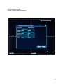
5.2.4 Add User
The Add User screen (refer to Fig. 23.4) contains the following parameters for adding user:
<User Name>: enter the new user name to be created
<Password>: enter the password
<Confirm>: re-enter the new password for confirmation
<Memo>: enter the memo
<Group>: select the group of authority
Option of Authority (Select/Deselect)
Shutdown the device
Channel Title
Schedule
Backup
HDD Management
PTZ Control
Account
Query System Information
Query Log Information
Clear Log
System Update
Auto Maintain
General coding
Encode Coding
RS232
Network
Alarm Set
Motion
PTZ Setting
Restore
Talk
Monitor_CH01
Monitor_CH02
Monitor_CH03
Monitor_CH04
Replay_CH01
Replay_CH02
Replay_CH03
Replay_CH04
☞Note: See each corresponding category setup for detail information
<OK>: exit with the changes
<Cancel>: go back without the changes
94
Fig. 23.4
95
5.2.5 Add Group
The Add Group screen (refer to Fig. 23.5) contains the following parameters for adding group
authority:
<Group>: enter the name of new group of authority to be created
<Memo>: enter memo
<
Authority>: select/deselect all options
Option of Authority (Select/Deselect)
Shutdown the device
Channel Title
Schedule
Backup
HDD Management
PTZ Control
Account
Query System Information
Query Log Information
Clear Log
System Update
Auto Maintain
General coding
Encode Coding
RS232
Network
Alarm Set
Motion
PTZ Setting
Restore
Talk
Monitor_CH01
Monitor_CH02
Monitor_CH03
Monitor_CH04
Monitor_CH05
Monitor_CH06
Monitor_CH07
Monitor_CH08
Replay_CH01
Replay_CH02
Replay_CH03
Replay_CH04
Replay_CH05
Replay_CH06
Replay_CH07
Replay_CH08
☞Note: See each corresponding category setup for detail information
<OK>: exit with the changes
<Cancel>: go back without the changes
96
Fig. 23.5
97
5.2.6 Delete User
The Delete User screen (refer to Fig. 23.6) contains the function to delete the user:
☞Note: The user name needs to be selected before clicking on <Delete User> tab for deletion.
“Confirm Delete”: click on <OK> to confirm the deletion,
<Cancel> tab: click on this tab to go back without deletion
Fig. 23.6
98
5.2.7 Delete Group
The Delete Group screen (refer to Fig. 23.2) contains the function to delete the group authority:
<Group Name>: select the group of authority to be deleted
<Delete> tab: click on this tab to delete the selected group of authority
“Confirm Delete”: click on <OK>to confirm the deletion
<Cancel> tab: click on this tab to go back without deletion
Fig. 23.7
99
5.3 Online Viewer
The Online Viewer screen (refer to Fig. 24) contains the function to check the online viewer’s loggedin status and disconnect the logged-in online viewer:
☞Note: The Online viewer’s user name needs to be selected for disconnection
<Disconnect> tab: click on to disconnect the selected online user
<Cancel> : to go back to the previous menu
Fig. 24
100
5.4 Display Adjustment
The Display Adjust screen (refer to Fig. 25) contains the function for the adjustment of on screen
display:
<Top Deflate>: pull the bar for the top screen adjustment
<Bottom Deflate>: pull the bar for the bottom screen adjustment
<Left Deflate>: pull the bar for the left screen adjustment
<Right Deflate>: pull the bar for the right screen adjustment
<Black Vertical>: pull the bar for the screen vertical position adjustment
<Black Horizontal>: pull the bar for the screen l Horizontal position adjustment
<OK>: exit with the changes
<Cancel>: go back without the changes
Fig. 25
101
5.5 Auto Maintenance
The AutoMaint screen (refer to Fig. 26) contains the function for auto maintenance:
Auto-Reboot System: setup the day and time for auto reboot
Auto-Delete Old Files: setup to delete the old recorded files
Fig. 26
102
5.6 Restore Factory Default
The Restore screen (refer to Fig. 27) contains the function for factory default value restore:
<All>: select to restore the default value of parameters for all categories which are under the Main
Menu
<General>: select to restore the default value of parameters for
Main Menu>[General]
<Encode>: select to restore the default value of parameters for
Main Menu>[Encode]
<Record Conf.>: select to restore the default value of parameters for
Main Menu> [Record Conf.]
<Alarm Set>: select to restore the default value of parameters for
Main Menu> [Alarm Set]
<Network>: select to restore the default value of parameters for
Main Menu> [Network]
<NetService>: select to restore the default value of parameters for
Main Menu> [NetService]
<GUI Display>: select to restore the default value of parameters for
Main Menu> [GUI Display]
<Account>: select to restore the default value of parameters for
Main Menu> [Account]
<OK> tab: click on the tab to restore
<Cancel> tab: go back to previous menu
103
Fig. 27
104
5.7 Update
The Update screen (refer to Fig. 28) contains the function for DVR firmware update.
☞Note: please store the updated firmware file to a USB flash drive and plug it into the USB port first.
< File Location> select the source of file location for system update
< File Name> select the file name for system update
<Update> tab: click on this tab to start the system update
☞Note: System will start the reboot to complete the firmware update process.
<Cancel> tab: go back to previous menu
Fig. 28
105
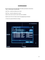
5.8 Miscellaneous Setting
The Miscellaneous setting screen (refer to Fig. 29) contains the following parameters for
miscellaneous setting:
<Audio In Channels>: enter the audio input channels
<Alarm In Channels>: not available on AD-600
<Alarm Out Channels>: not available on AD-600
<GUI Theme>: select the Graphic User Interface (GUI) theme
<Remote control type>: select the remote control type from the available list
<Maximum playback large ones>:
<Default playback large ones>”:
<OK> tab: exit with the changes
<Cancel> tab: go back without the changes
Fig. 29
106
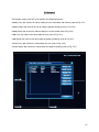
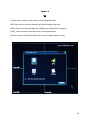
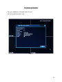
Chapter 6
Info
The Info screen (refer to Fig. 30) contains the following information:
[HDD Info]: select to view the information of hard disk capacity and status
[BPS]: select to view the information of the Bit Rate per Second (BPS) information
[LOG]: select to view the information of the system log information
[Version]: select to view the information of the system firmware/software version
Fig. 30
107
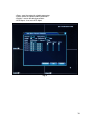
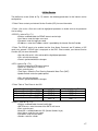
6.1 Hard Disk (HDD) Info
The HDD Info screen (refer to Fig. 31) contains the following two options to view the hard disk
information:
☞Note: Toggle on the tab (near the bottom of the screen) to switch between [View HDD capacity]
and [Current HDD content]
[View HDD capacity] tab: select to view the capacity, total size, and available size of HDD (refer to
Fig. 31)
[Current HDD content] tab: select to view the current hard disk content (refer to Fig. 31.1)
<Cancel> tab: go back without the changes
Fig. 31
108
Fig. 31-1
109
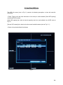
6.2 Bite per Second (BPS)
The Bite per second (BPS) information is displayed (refer to Fig. 32).
<Cancel> tab: go back to previous screen
Fig. 32
110
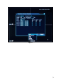
6.3 LOG Information
The LOG screen (refer to Fig. 30) contains the following information and functions:
<Type>: select the type of log information
<Start Time>: select the starting time for search
<End Time>: select the ending time for search
<Search> tab: select to start the search with the set conditions
<Remove> tab: click on this tab to remove the highlighted log information.
<<Cancel> tab: go back without the changes
Fig. 32
111
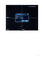
6.4 Version of Software
The system information is displayed (refer to Fig. 34).
<OK> tab: go back to previous menu
Fig. 34
112
Chapter 7
Logout
7.1 [Logout]: Select to logout from user login
7.2 [Shutdown]: Select to shut down the system
7.3 [Reboot]: Select to reboot the system
Click on “X” on top right hand corner to go to the previous screen
Fig. 35
113
114