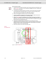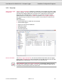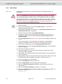
1
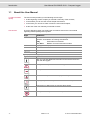
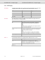
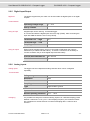
User Manual
GL1000/GL1010 – Compact Logger
Version 1.10
English
Imprint
Vector Informatik GmbH
Ingersheimer Straße 24
D-70499 Stuttgart
The information and data given in this user manual can be changed without prior notice. No part of this manual may be reproduced in
any form or by any means without the written permission of the publisher, regardless of which method or which instruments, electronic
or mechanical, are used. All technical information, drafts, etc. are liable to law of copyright protection.
© Copyright 2015, Vector Informatik GmbH. Printed in Germany.
All rights reserved.
80353
User Manual GL1000/GL1010 – Compact Logger
Table of Contents
Table of Contents
1
Introduction
3
1.1
About this User Manual
1.1.1
Certification
1.1.2
Warranty
1.1.3
Support
1.1.4
Registered Trademarks
4
5
5
5
5
2
GL1000/GL1010 – Compact Logger
7
2.1
General Information
2.2
Features
2.2.1
2.2.2
2.2.3
2.2.4
2.2.5
2.2.6
2.2.7
2.2.8
2.2.9
2.2.10
2.2.11
2.2.12
2.2.13
2.3
Operating Modes
18
2.4
Piggybacks
19
2.5
Technical Data
21
2.6
Included with Delivery
21
3
Installation Configuration Programs
23
3.1
Overview
24
3.2
Installation Vector Logger Configurator
3.2.1
Requirements
3.2.2
Setup
3.2.3
Overview
3.2.4
Quick Start
24
24
24
25
26
3.3
Installation G.i.N. Configuration Program
3.3.1
Requirements
3.3.2
Setup
3.3.3
Overview
3.3.4
Quick Start
27
27
27
28
29
4
Index
31
8
9
9
10
11
12
13
13
14
14
15
16
16
17
17
Connectors
SD/SDHC Memory Card
Serial Number
LED Display
Digital Input/Output
Analog Inputs
Serial Interface
Real-Time Clock with Battery
Beep
Wake-up / Sleep
CCP/XCP
Diagnostics
LOGview Control
© Vector Informatik GmbH
Version 1.10
-I-
User Manual GL1000/GL1010 – Compact Logger
Introduction
1 Introduction
In this chapter you find the following information:
1.1
About this User Manual
Certification
Warranty
Support
Registered Trademarks
© Vector Informatik GmbH
page 4
Version 1.10
-3-
Introduction
1.1
User Manual GL1000/GL1010 – Compact Logger
About this User Manual
To find information
quickly
The user manual provides you the following access helps:
> At the beginning of each chapter you will find a summary of the contents,
> In the header you can see the current chapter and section,
> In the footer you can see to which version the user manual replies,
> At the end of the user manual you will find an index.
Conventions
In the two following charts you will find the conventions used in the user manual
regarding utilized spellings and symbols.
Style
Utilization
bold
Blocks, surface elements, window- and dialog names of the
software. Accentuation of warnings and advices.
[OK]
Push buttons in brackets
File | Save
Notation for menus and menu entries
Windows
Legally protected proper names and side notes.
Source code
File name and source code.
Hyperlink
Hyperlinks and references.
<STRG>+<S>
Notation for shortcuts.
Symbol
Utilization
Here you can find additional information and hints that eases the
work with the loggers.
This symbol calls your attention to warnings.
Here you can find additional information.
Here is an example that has been prepared for you.
Step-by-step instructions provide assistance at these points.
Instructions on editing files are found at these points.
This symbol warns you not to edit the specified file.
-4-
Version 1.10
© Vector Informatik GmbH
User Manual GL1000/GL1010 – Compact Logger
Introduction
1.1.1 Certification
Certified Quality
Vector Informatik GmbH has ISO 9001:2008 certification.
Management System The ISO standard is a globally recognized standard.
1.1.2 Warranty
Restriction of
warranty
We reserve the right to change the contents of the documentation and the software
without notice. Vector Informatik GmbH assumes no liability for correct contents or
damages which are resulted from the usage of the user manual. We are grateful for
references to mistakes or for suggestions for improvement to be able to offer you
even more efficient products in the future.
1.1.3 Support
You need support?
You can get through to our hotline at the phone number
+49 711 80670-200
or you write an email to [email protected].
1.1.4 Registered Trademarks
Registered
trademarks
All trademarks mentioned in this user manual and if necessary third party registered
are absolutely subject to the conditions of each valid label right and the rights of
particular registered proprietor. All trademarks, trade names or company names are
or can be trademarks or registered trademarks of their particular proprietors. All rights
which are not expressly allowed, are reserved. If an explicit label of trademarks,
which are used in this user manual, fails, should not mean that a name is free of third
party rights.
> Windows, Windows XP, Windows Vista, Windows 7 and Windows 8 are
trademarks of the Microsoft Corporation.
> CANoe, CANalyzer and CANape are trademarks of the Vector Informatik GmbH.
© Vector Informatik GmbH
Version 1.10
-5-
User Manual GL1000/GL1010 – Compact Logger
GL1000/GL1010 – Compact Logger
2 GL1000/GL1010 – Compact Logger
In this chapter you find the following information:
2.1
General Information
page 8
2.2
Features
Connectors
SD/SDHC Memory Card
Serial Number
LED Display
Digital Input/Output
Analog Inputs
Serial Interface
Real-Time Clock with Battery
Beep
Wake-up / Sleep
CCP/XCP
Diagnostics
LOGview Control
page 9
2.3
Operating Modes
page 18
2.4
Piggybacks
page 19
2.5
Technical Data
page 21
2.6
Included with Delivery
page 21
© Vector Informatik GmbH
Version 1.10
-7-
GL1000/GL1010 – Compact Logger
2.1
User Manual GL1000/GL1010 – Compact Logger
General Information
GL1000
The GL1000 is a data logger with USB interface which processes CAN messages
with either 11-bit or 29-bit identifiers and LIN messages. Furthermore, received
messages and analog values can be logged on an inserted SD card. The
configuration of the logger is done with the Vector Logger Configurator or the G.i.N.
configuration program. The installation is described in chapter 3.
GL1010
The GL1010 is equivalent to the GL1000 and differs only in the design of the housing
and the connections (watertight according to IP65). The SD card is located in the
housing and is no longer accessible from the outside. The opening for the speaker is
eliminated.
Note: Please note that the housing of the GL1010 must not be opened under any
circumstances, since otherwise the IP65 protection class of the data logger is no
longer guaranteed. The SD/SDHC card, the piggybacks, and the battery may only be
replaced by Vector Informatik GmbH. For more information, please contact the Vector
Support.
Figure 1 – GL1000 (left), GL1010 (right)
Info: Due to the openings in the housing for the LED, leak tightness may not be
guaranteed if the label is damaged.
-8-
Version 1.10
© Vector Informatik GmbH
User Manual GL1000/GL1010 – Compact Logger
2.2
GL1000/GL1010 – Compact Logger
Features
2.2.1 Connectors
General information
The loggers have the following connectors:
> USB connector: data transfer between PC and logger
> HD DSUB25 connector containing:
2 CAN channels
2 LIN channels
2 digital inputs/outputs
4 analog inputs
Battery and ground
Ignition
> SD card slot (externally accessible for GL1000)
DSUB25
pin assignment
The pins of the HD DSUB25 connector have the following meaning. The colors refer
to the included connection cable.
Pin
Assignment
Color
Pin
Assignment Color
1
Battery
white
14
Opt3
N.C.
2
RS232 Rx
white/green
15
CAN1 High
yellow
3
RS232 Tx
N.C.
16
CAN1 Low
green
4
GND
brown
17
Opt4
N.C.
5
Opt1
N.C.
18
Opt5
N.C.
6
I/O 1
white/yellow
19
CAN2 High
grey
7
GND
brown
20
Wake
black
8
I/O 2
brown/yellow
21
CAN2 Low
pink
9
AnaIn 1
grey/pink
22
GND
brown
10
AnaIn 2
red/blue
23
LIN 1
lilac
11
AnaIn 3
blue
24
LIN 2
red
12
AnaIn 4
brown/green 25
Opt6
N.C.
13
Opt2
N.C.
The three GND pins are connected together internally and have the same potential as
the power supply ground.
Note: Transceivers with wake-up capability are supplied directly from the supply
voltage of the logger. During logger start, for the TJA1041 and TJA1054 transceivers
the supply voltage must not exceed 27 V in order to not damage the transceivers.
After start and during operation for these transceivers a supply voltage of maximum
30 V can be applied.
For a supply voltage of 27 V up to 30 V CAN we recommend for CAN high-speed the
transceiver TJA1043.
© Vector Informatik GmbH
Version 1.10
-9-
GL1000/GL1010 – Compact Logger
Connection cable
User Manual GL1000/GL1010 – Compact Logger
The included connection cable has open wire ends. If single wires are not used, it is
recommended to terminate them. This prevents short circuits between the open
wires. At the same time the EMC properties are improved.
Info: The connection cable does not match IP65.
Caution: It is recommended to connect the logger to the same voltage supply (e.g.
battery of the vehicle) as the vehicle or test equipment, respectively.
If two different voltage supplies are used for the logger and the test equipment, the
ground (GND) pins of the two voltage supplies must be connected.
GL1010 USB
connector
It is recommended to protect the USB connector with a cap if no USB cable is
connected.
2.2.2 SD/SDHC Memory Card
SD and SDHC cards
The logger supports industrial grade SD cards up to 2 GB. From serial number 220
and higher also industrial grade SDHC cards are supported (firmware V1.08 and
higher is required).
For the proper use only the industrial grade cards released by Vector may be used.
These cards are listed below. Currently memory cards with industrial grade are
available up to and including 16 GB.
Recommended
SD cards
The following SD cards with industrial grade are recommended (see also section 2.5):
> Xmore industrial 2 GB (SD-2G0-XIWE2, SD-2G0-XIWE21)
> Cactus Industrial Grade 2 GB (KS 2GRI-800), some higher start-up time
Recommended
SDHC cards
The following SDHC cards with industrial grade are recommended (see also
section 2.5):
> Xmore industrial 4 GB (SD-4G0-XIE6, SD-4G0-XIWE21, SD-4G0-XIE23)
> Xmore industrial 8 GB (SD-8G0-XIE6, SD-8G0-XIWE21, SD-8G0-XIE23)
> Xmore industrial 16 GB (SD-16G-XIE23)
> Cactus Industrial Grade 4 GB (KS 4GRI-800)
> Cactus Industrial Grade 8 GB (KS 8GRI-800)
GL1000:
Inserting and
removing SD card
The GL1000 has a push-and-pull card holder for inserting and removing the SD card.
To insert the SD card, push it in until the locking mechanism engages securely. To
remove the SD card, push it slightly into the card holder until it unlocks. Now, release
the SD card. The card moves from its original position and can now be removed.
Do not pull the SD card from the card holder forcefully, since this could cause
mechanical damage!
- 10 -
Version 1.10
© Vector Informatik GmbH
User Manual GL1000/GL1010 – Compact Logger
GL1010: SD card
GL1000/GL1010 – Compact Logger
The SD card is already contained in the housing of the GL1010 and cannot be
removed or replaced.
Note: Please note that the housing of the GL1010 must not be opened under any
circumstances, since otherwise the IP65 protection class of the data logger is no
longer guaranteed. The SD/SDHC card may only be replaced by Vector Informatik
GmbH. For more information, please contact the Vector Support.
Data transfer
The logged data can be downloaded from the SD/SDHC card in the GL1000/GL1010
or in an SD/SDHC card reader. In both cases for the download and the conversion
the configuration program is required. It is not possible to access the logged data on
the memory card directly through the Windows Explorer because of the logger’s own
file system.
Note: Laptops with an integrated SD card reader rarely cannot identify SD cards with
a logger specific file system. In this case please use an external USB card reader.
Caution: A formatted SD/SDHC card has to be empty before inserting it in the
logger! The configured logger will delete all files if a formatted memory card is
not empty!
The logger deletes the Windows files and the file system on the memory card on start
of logging mode if they exist. The logger uses its own file system that cannot be seen
in the Windows Explorer. It is required to use a configuration program to download a
configuration and upload logging files.
2.2.3 Serial Number
Serial number
The serial number is stored in the logger and is copied to the SD card after download
of the configuration and start in logging mode.
The configuration program reads out the serial number of the logger in the
configuration mode. The serial number is displayed correctly, if an SD card is inserted
and the logger was at least one time in the logging mode with this SD card. If this SD
card is inserted in another logger and the logger is not started in logging mode
afterwards, the serial number of the first logger will be displayed in the configuration
program.
© Vector Informatik GmbH
Version 1.10
- 11 -
GL1000/GL1010 – Compact Logger
User Manual GL1000/GL1010 – Compact Logger
2.2.4 LED Display
LED display
LED USB
The logger has five LEDs. LED 1 to LED 4 are free programmable. They can be used
to display different states. LED USB indicates the USB connection to the PC.
LED
Color
Programmable
LED 1
Green
Yes
LED 2
Yellow
Yes
LED 3
Red
Yes
LED 4
Red
Yes
LED USB
Green
No
This LED displays the state of the USB connection between the logger and the PC.
Note, that this LED is not programmable.
State
Meaning
On
USB connected and SD card inserted. The logger is
registered on the PC and ready for data transfer via
USB.
Note:
The LED will be on (determined by the system) if the SD
card is removed in this state.
Slow blinking
(1 Hz)
USB connected, but SD card is not inserted.
The logger is registered on the PC. Due to missing SD
card no data transfer is possible.
Note:
If an SD card is inserted in this state, the LED will be
switched on. The logger is now ready for data transfer.
LEDs 1–4
- 12 -
Fast blinking
Data transfer
Off
All other cases
In the following situations in the Logging mode the display of LEDs 1–4 is fix.
State
Meaning
Running light over LEDs
1–4
At the first start in Logging mode after a configuration
download from PC a running light over LEDs 1–4
indicates the internal update and setup of ring buffers on
the memory card (firmware up to 0.96).
Simultaneous blinking of
LEDs 1–4
Fault due to missing or defective SD card.
Version 1.10
© Vector Informatik GmbH
User Manual GL1000/GL1010 – Compact Logger
GL1000/GL1010 – Compact Logger
2.2.5 Digital Input/Output
Digital IO
The logger supports two pins which can be used either as digital inputs or as digital
outputs.
Technical data
Using as input
Operating voltage range
0 V…36 V
Pull-up resistor
10 kΩ to 5 V
A digital input can be used e.g. as external trigger.
In unconnected state the digital inputs are set to High (TRUE). After connecting the
input with GND the status is set to Low (FALSE).
Using as output
Threshold Low → High
1.9 V
Threshold High → Low
0.5 V
Sampling rate
1 kHz
When used as a digital output, the pin is connected to GND when the output is
switched on (so called “low side switch”). To switch a consumer it is necessary to
connect it between the pin of the digital output and the battery.
Current when switched on
Max. 500 mA
Circuit time
Typ. 1ms
2.2.6 Analog Inputs
Analog inputs
The logger has four independent analog channels which can be configured
separately.
Technical data
Voltage range
0 V … 16 V
Resolution
10 bit
Precision
1%
Sampling rate
Max. 1 kHz
Type
Single-ended to ground
Input resistance
155.6 kΩ
Reverse-polarity protection -50 V … +50 V
Averaging
It is possible to average the measured analog inputs over a defined sampling period
between 1 kHz and 1 Hz. E.g. for a 1 Hz sampling frequency, the measured values
are averaged over the last second. The internal sampling rate is 1 kHz for each
channel.
© Vector Informatik GmbH
Version 1.10
- 13 -
GL1000/GL1010 – Compact Logger
User Manual GL1000/GL1010 – Compact Logger
2.2.7 Serial Interface
RS232
The serial interface with the Rx and Tx lines is a logging interface only. The baudrate
of the interface can be configured. Received data can be stored on the SD card as
CAN messages.
Info: The serial interface cannot be used to download a configuration or upload
logging data.
2.2.8 Real-Time Clock with Battery
Real-time clock
The GL1000/GL1010 has an internal real-time clock, which is battery supplied, and
thus continues running even if the logger is disconnected from power supply. The
real-time clock inside the logger is required to store the date and time together with
the logged data.
It is recommended to set the real-time clock before first logging.
The configuration of the clock is done with the configuration program (SD card must
be inserted). After setting the real-time clock the logger is switched off.
Older logger under
Windows 7 and
Windows 8
When the real-time clock of older GL1000/GL1010 is set under Windows 7 / Windows
8, the concluding ejection of the logger must be performed manually for hardware
reasons. This pertains to the following serial numbers:
> GL1000 up to and including serial number 028069-001339
> GL1010 up to and including serial number 028081-100105
The affected loggers must be connected to the USB and be supplied with power via
the DSUB25 connector before the time is set. After the time is set with the
configuration program, the USB connection must be disconnected immediately so
that the time will be applied.
Under Windows XP, the USB connection is adequate for setting the time for all
GL1000/GL1010; the same applies under Windows 7 / Windows 8 for newer serial
numbers than those indicated above.
Battery
The internal battery supplies the real-time clock only. The battery has a typical
durability of approximately 5-10 years under the following conditions:
T = +40°C to +80°C for at most 40 hours per week
T = -40°C to +40°C in the rest of the time
GL1010: Battery
- 14 -
Please note that the housing of the GL1010 must not be opened under any
circumstances, since otherwise the IP65 protection class of the data logger is no
longer guaranteed. The battery may only be replaced by Vector Informatik GmbH. For
more information, please contact the Vector Support.
Version 1.10
© Vector Informatik GmbH
User Manual GL1000/GL1010 – Compact Logger
GL1000:
Replacing battery
GL1000/GL1010 – Compact Logger
The battery of the GL1000 can be is exchanged after life cycle end.
Notes:
> First read the installation instruction completely.
> The case has to be opened to exchange the piggybacks.
> This must be done very cautiously and carefully.
Caution: When performing this operation be sure not to touch the top or bottom of
the boards (logger main board or piggybacks).
The battery is exchanged as follows:
1. First remove the two black decorative caps and the screws from the bottom cover
of the GL1000. The bottom cover contains the DSUB25 connector. Carefully pull
out the main circuit board.
2. You will find mounting location almost at the center of the main circuit board,
partly covered by the piggybacks (see green circle in Figure 2).
3. Remove the piggybacks for easier access to the battery.
4. Remove the battery carefully from the mounting location.
5. Insert the replacement battery. Look out for the correct polarity, + must be on top.
Please handle the contact spring with care. Do not bend it too much and make
sure the spring has contact to the new battery after replacement.
6. Place the GL1000 main board back in the housing verifying that it is inserted
properly. This operation involves placing the housing on a table with its back side
(side with the bar code) facing up. Then the main board is inserted into the lower
guide rail with the piggybacks facing up.
7. It should be possible to slide the main board in the housing up to a few
millimeters from the end without forcing it in. Close the housing by applying light
pressure, and then secure it with the appropriate screw fasteners. The screws
should be secure but not excessively tight.
8. Please also attach the two black decorative caps.
Dispose of the removed battery according to the applicable laws (e.g. the Battery Law
in Germany).
2.2.9 Beep
Beep
The GL1000/GL1010 has a speaker that acoustically alerts the user e.g. in case of a
trigger. Triggers and beep can be defined using the configuration program.
Because the opening in the housing has been eliminated, the signal tone of the
speaker is only audible to a limited extent in the GL1010.
© Vector Informatik GmbH
Version 1.10
- 15 -
GL1000/GL1010 – Compact Logger
User Manual GL1000/GL1010 – Compact Logger
2.2.10 Wake-up / Sleep
Wake-up
The GL1000/GL1010 starts after power on. A sleeping logger wakes up
> after reception of a CAN message
> after reception of a LIN message
> positive edge on the wake line (clamp 15)
> wake-up timer via real-time clock
The logger has to be equipped with CAN transceivers with wake-up capability to
support the wake-up functionality on CAN (see section 2.4 Piggybacks).
The wake-up line resists the full board voltage. If the GL1000 is supplied from clamp
30, the wake-up line can be connected with clamp 15. Thereby the GL1000 will be
woken up immediately at switching on the ignition even if no activity is on the wake-up
compatible busses or the busses are not connected.
Sleep
The logger can be configured to go to sleep mode if no CAN and LIN messages are
received for a defined time. This time can be configured (max. 18000 s = 5 h).
2.2.11 CCP/XCP
Overview
The GL1000/GL1010 supports the recording of CCP/XCP data in DAQ and polling
mode. The A2L file is inserted directly in the Vector Logger Configurator and the
signals to be measured are selected.
For ECUs which are protected via Seed & Key procedure CANape is also required to
program the Seed & Key algorithm and create an SKB file containing this algorithm.
This SKB file is added to the logger configuration.
CCP/XCP is available as option. The license must be installed in the logger. The
license also includes the Seed & Key support.
FAQ
- 16 -
Measurement mode
DAQ (data aquisition) mode, polling mode
Supported CCP version
CCP 2.0 und CCP 2.1
Supported XCP version
XCP 1.0 and higher
Support CANape
CANape V6.0 or higher for ECUs without Seed & Key
CANape V7.0 or higher for ECUs with Seed & Key
CANape V13.0 or higher for polling mode
A2L file
Direct import in Vector Logger Configurator
Import in CANape still available
Number of ECUs
Multiple ECUs possible
Version 1.10
© Vector Informatik GmbH
User Manual GL1000/GL1010 – Compact Logger
GL1000/GL1010 – Compact Logger
2.2.12 Diagnostics
Overview
The GL1000/GL1010 supports the logging of diagnostic data via CAN bus.
The diagnostic descriptions (CDD, ODX, PDX, MDX) are read into the Vector Logger
Configurator. These files are necessary to set the communication parameters and to
select the diagnostic service requests that would be sent on different events. The
analysis is supported in CANoe/CANalyzer.
FAQ
Diagnostic descriptions
CDD (CANdela diagnostic descriptions) up to V7.1
ODX/PDX V2.0.1 and V2.2.0
MDX V3.0
Supported transport
protocol
ISO-TP
Supported addressing
modes
Normal
Normal fixed
Extended
Supported diagnostic
protocols
KWP2000, UDS
Seed & Key
Not supported
Number of ECUs
Several ECUs on different CAN buses possible
2.2.13 LOGview Control
Overview
The GL1000/GL1010 supports the connection of a LOGview display.
The connection is made via CAN channel CAN2 thus CAN2 cannot longer be used
unlimited. CAN2 can be used additionally for the logging of CAN messages of a CAN
network, if the CAN network will not be disturbed by CAN messages (standard IDs
0x400 – 0x43F) that are transmitted between logger and display. Precondition
therefor is that the network uses the required LOGview baud rate of 500 Kbit/s. The
required bus terminating resistor of 120 Ohm is installed internally within the
LOGview.
The CAN data traffic between GL1000/GL1010 and LOGview will not be logged and it
will not influence the sleep behavior of the logger. The data traffic is also “hidden” for
the LTL configuration.
Electrical connection
For the electrical connection of the LOGview to the logger, a 5-pin Binder connector
must be wired with the DSUB25 connector of the logger. Therefor two variants are
possible that can be selected depending on the use case.
© Vector Informatik GmbH
Version 1.10
- 17 -
GL1000/GL1010 – Compact Logger
Variant 1
User Manual GL1000/GL1010 – Compact Logger
The display is on if the ignition (clamp 15) is on.
LOGview Pin Color
Description
GL1000 DSUB25 Pin
1
gray
On/Off
N.C.
2
brown
GND, together with
vehicle ground
4 (GND)
3
yellow
CAN High
19 (CAN2 High)
4
green
CAN Low
21 (CAN2 Low)
5
white
Vbatt, together with
clamp 15 of the vehicle
20 (Wake)
Additionally the GL1000/GL1010 must be supplied at least via PIN 1 (battery) of the
DSUB25 connector from the vehicle.
Variant 2
The display is on if the logger is awake.
LOGview Pin Color
Description
GL1000 DSUB25 Pin
1
gray
On/Off
6 (I/O 1)
2
brown
GND, together with
vehicle ground
4 (GND)
3
yellow
CAN High
19 (CAN2 High)
4
green
CAN Low
21 (CAN2 Low)
5
white
Vbatt, together with
clamp 30 of the vehicle
1 (battery)
This variant requires an additional resistor of 33 kOhm between pin 4 and 6 of the
DSUB25 connector. Without this resistor the LOGview is permanently on, which can
be identified by the active background illumination.
Additionally with this variant the LOGview can be switched on and off via LTL
programming (see LTL user manual).
2.3
Operating Modes
Overview
The GL1000/GL1010 supports two operating modes, which are switched by using the
USB connection and power supply respectively.
USB connection
Voltage supply
Mode
yes
optional
Configuration mode
no
yes
Logging mode
Configuration mode
In the Configuration mode the logger can be configured with the configuration
program. The configuration can be downloaded to the logger. Logging data from the
SD card can be uploaded to the PC.
Logging mode
The Logging mode enables the PC independent usage of the logger and allows the
logging of CAN, LIN and analog values. For this case the logger must be unplugged
from the USB connector of the PC. The voltage supply is done externally by the
DSUB25 connector.
- 18 -
Version 1.10
© Vector Informatik GmbH
User Manual GL1000/GL1010 – Compact Logger
2.4
GL1000/GL1010 – Compact Logger
Piggybacks
Piggybacks
A piggyback is a plug-in PC-board which implements the interconnection of the logger
to a specific CAN bus by the use of various transceivers. The piggybacks are also
used in other loggers.
Available piggybacks for the GL1000 series:
CAN Piggyback
Transceiver
Description
Wake-up
1
TJA1043
CAN High-speed
Yes
2
Piggyback 1042
TJA1042
CAN High-speed
No
Piggyback 1050
TJA1050
CAN High-speed
No
Piggyback 1055
TJA1054
CAN Low-speed
Yes
Piggyback Single Wire
TLE6255G
CAN Single Wire
Yes
Piggyback Truck Trailer
WABCO
CAN Truck&Trailer
Yes
Piggyback 1043
3
1
Piggyback 1043 as successor of Piggyback 1041
2
Piggyback 1042 as successor of Piggyback 251
3
Piggyback 1055 as successor of Piggyback 1054
Note: Transceivers with wake-up capability are supplied directly from the supply
voltage of the logger. During logger start, for the TJA1041 and TJA1054 transceivers
the supply voltage must not exceed 27 V in order to not damage the transceivers.
After start and during operation for these transceivers a supply voltage of maximum
30 V can be applied.
LIN transceiver
The LIN transceivers TJA1020/TJA1021 are already mounted on the main board of
the GL1000/GL1010. Therefore LIN piggybacks are not needed.
LIN level
The LIN transceivers are supplied from the supply voltage. On this way reference
voltage for the LIN levels and supply voltage have the same value. For example if the
logger is supplied with 24 V, the reference value for LIN is also 24 V.
GL1010: Piggybacks
Please note that the housing of the GL1010 must not be opened under any
circumstances, since otherwise the IP65 protection class of the data logger is no
longer guaranteed. The piggybacks may only be replaced by Vector Informatik
GmbH. For more information, please contact the Vector Support.
GL1000:
Replacing
piggybacks
The CAN piggybacks can be exchanged for the GL1000. The installed piggybacks
are automatically detected (“plug & play”).
Notes:
> First read the installation instruction completely.
> The case has to be opened to exchange the piggybacks.
> This must be done very cautiously and carefully.
Caution: When performing this operation be sure not to touch the top or bottom of
the boards (logger main board or piggybacks).
© Vector Informatik GmbH
Version 1.10
- 19 -
GL1000/GL1010 – Compact Logger
User Manual GL1000/GL1010 – Compact Logger
Now proceed as follows:
1. First remove the two black decorative caps and the screws from the bottom cover
of the GL1000. The bottom cover contains the DSUB25 connector. Carefully pull
out the main circuit board.
2. You will find the mounting location for channel 1 close to the center of the main
circuit board and the mounting location for channel 2 close to the edge of the
main circuit board. The locations are marked red in Figure 2.
3. Remove the piggyback carefully from the mounting location.
4. Insert the replacement piggyback. When doing this please make sure that the
single and dual-row connectors are not laterally shifted.
5. Place the GL1000 main board back in the housing verifying that it is inserted
properly. This operation involves placing the housing on a table with its back side
(side with the bar code) facing up. Then the main board is inserted into the upper
guide rails with the piggyback facing up.
6. It should be possible to slide the main board in the housing up to a few
millimeters from the end without forcing it in. Close the housing by applying light
pressure, and then secure it with the appropriate screw fasteners. The screws
should be secure but not excessively tight.
7. Please also attach the two black decorative caps.
Layout
GL1000/GL1010
Figure 2 – Layout GL1000/GL1010
- 20 -
Version 1.10
© Vector Informatik GmbH
User Manual GL1000/GL1010 – Compact Logger
2.5
GL1000/GL1010 – Compact Logger
Technical Data
Start-up time
PC interface
USB 2.0
Channels
2 CAN channels (via piggybacks)
2 LIN channels
Analog inputs
4 inputs:
- Resolution 10 bit (1% precision)
- Sampling rate 1 kHz
- Voltage range 0 V…16 V
Digital inputs/outputs
2 inputs/outputs, 0 V…36 V
Start-up time
Typ.150 ms with delivered 2 GB Xmore SD card, time
varies with capacity and type of the SD/SDHC card
Power consumption
Typ. 660 mW, max. 1100 mW
Current consumption
Operation:
Sleep mode:
Temperature range
GL1000: -40°C…+85°C depending on SD card
GL1010: -20°C…+80°C (because of connector)
USB interface: 0°C…+70°C
Power supply
5 V…30 V, typ. 12 V
Shut-down voltage
4.5 V
Dimensions (LxWxH)
GL1000: approx. 107 mm x 85 mm x 35 mm
GL1010: approx. 130 mm x 85 mm x 35 mm
Battery
Lithium primary cell, BR2032 type
typ. 55 mA at 12 V DC
typ. 160 µA (2x CAN and 2x LIN)
Data is recorded after the given start-up time if the GL1000/GL1010 already contains
a configuration. Updating the configuration or using a new SD card increases this
start-up time.
Cross reference: The recommended SD/SDHC cards are listed in section 2.2.2
SD/SDHC Memory Card.
2.6
Included with Delivery
Standard scope of
delivery
> GL1000/GL1010 Logger
> Vector Logger Configurator on CD
> G.i.N. configuration program on CD
> Manuals on CD
> USB cable
> 2 GB SD memory card
> Connection cable (open ends)
> Mounting brackets (GL1000 only)
Optional
> CCP/XCP license for CAN
© Vector Informatik GmbH
Version 1.10
- 21 -
User Manual GL1000/GL1010 – Compact Logger
Installation Configuration Programs
3 Installation Configuration Programs
In this chapter you find the following information:
3.1
Overview
page 24
3.2
Installation Vector Logger Configurator
Requirements
Setup
Overview
Quick Start
page 24
3.3
Installation G.i.N. Configuration Program
Requirements
Setup
Overview
Quick Start
page 27
© Vector Informatik GmbH
Version 1.10
- 23 -
Installation Configuration Programs
3.1
User Manual GL1000/GL1010 – Compact Logger
Overview
Overview
This instruction describes the installation of the software package for the
GL1000/GL1010 containing:
> Vector Logger Configurator
Graphic user interface for easy configuration
> G.i.N configuration program
User interface to create complex configurations with LTL (Log Task Language)
The programs are included with delivery.
Vector Logger
Configurator
The Vector Logger Configurator offers a wide range of features to easily create
configurations for the logger. The Vector Logger Configurator also supports the
download of the configuration and the upload of logging data including the export to
different file formats. Additionally the configuration can be saved as LTL code to be
used in the G.i.N. configuration program.
G.i.N. configuration
program
The G.i.N. configuration program can be used as configuration program for high end
configurations. It offers full support of all features available with LTL (Log Task
Language). This program can be used to import LTL code from the Vector Logger
Configurator or from existing configurations written in LTL or to write own
configurations in LTL.
3.2
Installation Vector Logger Configurator
Overview
This instruction describes the installation of the Vector Logger Configurator 2.1 or
higher for the GL1000/GL1010 containing:
> Vector Logger Configurator
Logging configuration
> Online help for the Logger Configurator
> User manual for the Logger Configurator
> This user manual
3.2.1 Requirements
Operating system
The following software requirements must be fulfilled to run the Vector Logger
Configurator:
Windows XP SP3, Windows Vista SP1, Windows 7 / Windows 8 (32/64 bit)
Restriction Windows 8: AUTOSAR databases are not supported.
3.2.2 Setup
The Vector Logger Configurator is installed as follows.
1. Execute the setup, which is found on the installation CD: .\VLConfig\Setup.exe
2. Please, follow the instructions in the setup program to complete the installation.
3. After successful installation, the Vector Logger Configurator can be found in the
start menu (if selected during installation).
- 24 -
Version 1.10
© Vector Informatik GmbH
User Manual GL1000/GL1010 – Compact Logger
Installation Configuration Programs
3.2.3 Overview
About Vector Logger
Configurator
Vector Logger Configurator enables the configuration of the loggers and offers a wide
range of settings. You may set baud rates for CAN and LIN, define triggers and filters,
set LEDs and manage logging files on the SD card. Furthermore for the CAN bus
diagnostics and CCP/XCP can be configured. For CCP/XCP the logger needs a
installed license. For Seed & Key CANape is required. Vector Logger Configurator
also supports trigger and filter access by symbolic names defined in CAN and LIN
databases.
Main features are:
> Customizable filters for CAN and LIN messages
> Customizable triggers
> Support of CAN and LIN databases
> Diagnostic support
> File management
> CCP/XCP (optional)
Device Information
The Vector Logger Configurator can read out hardware information from the logger.
Connect the GL1000/GL1010 with inserted SD card via USB and select the item File
Manager|Device Information in the list view on the left hand side.
Cross reference: The Vector Logger Configurator is described in detail in the user
manual of this configuration program. The user manual is available as PDF and can
be opened via the program group in the start menu.
© Vector Informatik GmbH
Version 1.10
- 25 -
Installation Configuration Programs
3.2.4
User Manual GL1000/GL1010 – Compact Logger
Quick Start
Quick start
Follow the instructions below to configure the logger, start logging and read out
logging data.
Caution: A formatted SD card has to be empty before inserting in the logger!
The configured logger will delete all files if a formatted SD card is not empty!
The logger deletes the Windows files and the file system on the SD card on start of
logging mode if they exist. The logger uses its own file system that cannot be seen in
the Windows Explorer. It is required to use the Vector Logger Configurator to
download a configuration and upload logging files.
1. Start the program.
2. Open a new configuration via the menu File|New Project…. Select in the
displayed dialog the logger type.
3. Select suitable baud rates for CAN and/or LIN (Hardware|CAN Channels and/or
Hardware|LIN Channels), respectively.
4. Select the timeout to sleep mode (Hardware|Settings).
5. Configure the logger for a permanent logging of all data from switching on to
switching off of the logger by activating the Use permanent logging option in
Logging|Triggers.
6. Insert an empty SD card into the GL1000. The SD card is already included in the
GL1010.
7. Connect the logger to PC via USB cable. If the logger is not automatically
detected, press <F5> to refresh the display of connected logger devices.
8. Download the configuration via menu Configuration|Write to Device….
9. Set the real-time clock via menu Device|Set Real-Time Clock… (recommended
before first logging).
10. Disconnect the logger from the PC.
11. Connect the logger e.g. to your test system (CAN bus). Switch power on via
connecting cable on DSUB25.
12. Start logging. LED1 flashes permanently (standard setting for new configurations,
can be configured).
13. Stop logging by switching off CAN. Wait until the logger goes to sleep mode (CAN
transceiver with wake-up capability necessary) i.e. LED1 must be off.
14. Connect the logger to PC via USB cable.
15. Open the File Manager node in the tree view.
16. Click on Logger Device. Now the logging files are displayed.
17. Select in the General Settings the destination folder and the format for the
converted files.
18. Select in the Advanced Settings the options for conversion.
19. Click on the [Convert] button to start the readout and conversion of all data. The
files will be located in <Destination folder>/<Destination
subdirectory>.
- 26 -
Version 1.10
© Vector Informatik GmbH
User Manual GL1000/GL1010 – Compact Logger
3.3
Installation Configuration Programs
Installation G.i.N. Configuration Program
Overview
This instruction describes the installation of the G.i.N. Configuration Program for the
GL1000/GL1010 containing:
> G.i.N. configuration program
Logging configuration
> G.i.N. user manuals for the configuration program and the hardware
3.3.1 Requirements
Operating system
The following software requirements must be fulfilled to run the G.i.N. configuration
program:
Windows XP SP2, Windows 2000, Windows Vista, Windows 7
3.3.2 Setup
Follow the instructions below to install the G.i.N. configuration program:
1. Execute the setup, which is found on the installation CD:
.\GiNconf\setup.exe
2. Please, follow the instructions found there to complete the installation.
3. After successfully installation, the G.i.N. configuration program can be found in
the start menu.
© Vector Informatik GmbH
Version 1.10
- 27 -
Installation Configuration Programs
User Manual GL1000/GL1010 – Compact Logger
3.3.3 Overview
About G.i.N.
configuration
program
The G.i.N. configuration program enables the configuration of the loggers and offers a
wide range of settings via LTL (Log Task Language). You may set baud rates for
CAN and LIN, define triggers and filters, set LEDs and manage logging files on the
SD card. CCP/XCP can also be configured with the means of CANape, if the license
is installed. G.i.N. configuration program also supports trigger and filter access by
symbolic names defined in CANdb databases.
Main features are:
> Customizable filters for CAN and LIN messages
> Customizable complex triggers
> Support of databases
> File management
> CCP/XCP (optional)
Cross reference: The G.i.N. configuration program is described in detail in the LTL
user manual of the configuration program. The LTL user manual is available as PDF
after installation of the program and can be called by the Help menu.
- 28 -
Version 1.10
© Vector Informatik GmbH
User Manual GL1000/GL1010 – Compact Logger
Installation Configuration Programs
3.3.4 Quick Start
Quick start
Follow the instructions below to configure the logger, start logging and readout
logging data.
Warning: A formatted SD card has to be empty before inserting in the logger!
The configured logger will delete all files if a formatted SD card is not empty!
The logger deletes the Windows files and the file system on the SD card on start of
logging mode if they exist. The logger uses its own file system that cannot be seen in
the Windows Explorer. It is required to use the G.i.N. configuration program or the
Vector Logger Configurator to download a configuration and upload logging files.
1. Start the program.
2. Create a new project (File|New Project). Select the project path and the device
GL1000.
3. Create a new source file (File|New File) and set the baud rate for CAN and the
timeout for sleep mode, e.g.
SYSTEM
Can1Timing
= Timing500K
Can2Timing
= Timing500K
SleepSeconds = 5
END
4. Save the file (File|Save File as) as LTL file in your project directory.
5. Compile this file via Project|Compile or press [F9]. A COD file is created.
6. Insert an empty SD card in the logger. The SD card is already included in the
GL1010.
7. Connect the logger to PC via USB cable.
8. Download the COD file with [F10] or via Project|Compile and Download.
9. Disconnect the logger from PC.
10. Connect the logger e.g. to your test system (CAN bus). Switch power on via
connecting cable on DSUB25.
11. Start logging.
12. Stop logging by switching off CAN. Wait until the logger goes to sleep mode (CAN
transceiver with wake-up capability necessary).
13. Connect logger to PC via USB cable.
14. Start the control program with [F11] or via Project|Run Control Program. Select
Read out and Export after readout for the CAN logfile and click on [OK].
15. Select the destination directory for the logging files. The upload is started
afterwards.
16. The log files are uploaded in a raw format and displayed in the tree view under
Logfiles GIN-Logger.
17. After readout the Export dialog is automatically displayed. Select the file format
and export parameters and click on [OK]. The raw log file is now converted to the
selected file format.
© Vector Informatik GmbH
Version 1.10
- 29 -
User Manual GL1000/GL1010 – Compact Logger
Index
4 Index
A
M
Analog inputs ......................................................13
Memory cards .................................................... 10
B
O
Battery................................................................. 14
Operating modes ............................................... 18
Beep.................................................................... 15
P
C
Piggybacks ......................................................... 19
CAN .................................................................... 19
Pin assignment .................................................... 9
CCP/XCP ............................................................ 16
Configuration mode ............................................18
Connection cable ................................................10
Connectors ........................................................... 9
Q
Quick start .................................................... 26, 29
R
Real-time clock .................................................. 14
D
Delivery ............................................................... 21
Requirements ............................................... 24, 27
Device information ..............................................25
S
Diagnostics .........................................................17
SD/SDHC ........................................................... 10
Digital input/output ..............................................13
Serial interface ................................................... 14
DSUB25 ................................................................ 9
Serial number ..................................................... 11
Sleep .................................................................. 16
F
Features ................................................................ 9
G
GiN Configuration Program ................................27
L
Start-up time ...................................................... 21
Support ................................................................ 5
T
Technical data .................................................... 21
Transceiver ........................................................ 19
Layout GL1000/GL1010 .....................................20
LED ..................................................................... 12
LIN ...................................................................... 19
V
Vector Logger Configurator ............................... 24
Logging mode .....................................................18
W
LOGview ............................................................. 17
Wake-up ............................................................. 16
© Vector Informatik GmbH
Version 1.10
- 31 -
Get more Information!
Visit our Website for:
> News
> Products
> Demo Software
> Support
> Training Classes
> Addresses
www.vector.com