1
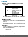
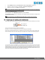
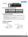
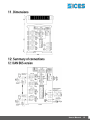
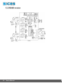
Filename: EAAM036903EN.docx Rev. 03 Date: 28/05/2013 ID Document: EAAM0369 Product: DIVIT ii 1. GENERAL CHARACTERISTICS .............................................................................. 3 1.1 VERSIONS AVAILABLE ....................................................................................... 3 2. TECHNICAL SPECIFICATIONS ............................................................................... 4 2.1 INDICATORS ....................................................................................................... 5 3. MODBUS SPECIFICATIONS .................................................................................... 5 4. CanBus specifications (EX-BUS proprietary protocol) ........................................ 8 5. Differential reading .................................................................................................. 8 6. Conditions ................................................................................................................ 8 7. Using with 8 out relay board ................................................................................. 10 8. Configuration ......................................................................................................... 10 8.1 Select type of reading and end-of-scale ............................................................. 11 8.2 Setting the electrical sensors-signals correspondence ....................................... 12 8.3 Switch settings .................................................................................................... 12 8.3.1 SWN switches for RS485 Version ................................................................ 12 8.3.2 SWN switches for CanBus Version .............................................................. 12 8.3.3 JP serial interface configuration switch ........................................................ 13 9. Installation instructions ........................................................................................ 13 10. Sensor connections .............................................................................................. 13 10.1 Voltage input ................................................................................................ 13 10.2 Current Input ................................................................................................ 14 11. Dimensions ............................................................................................................ 15 12. Summary of connections ...................................................................................... 15 12.1 CAN BUS version ......................................................................................... 15 12.2 RS485 version .............................................................................................. 16 User’s Manual The DIVIT device acquires voltage or current signals on four different channels galvanically isolated from each other and the power lines. They can be used with 0..5V or 0..10V voltage signals, or in 0..10 or 0..20mA current loop. Each independent channel can be associated with a reading magnitude by setting appropriate parameters for the corresponding measured electric/magnitude signal values of two known characteristic points; correspondence should be linear. The value of the measured magnitude is transmitted directly. The format of the data transmitted has an absolute dynamic ranging from -273 to +1735 with selectable decimal point position. A descriptive alphanumeric string can be set for each channel on the SICES DST4601/PX boards, and the unit of measure of the magnitude measured by the sensor defined in it. Both active and passive sensors can be used. The device is available in two versions, with CANBUS or MODBUS RS485 communication; both versions have galvanically isolated communication lines. A further (non isolated) RS232 connection is available via Jack to configure the device. Connection with SICES boards is via CANBUS, with dedicated EXBUS protocol. The device has an output connector for controlling the optional SICES E610209350XXX, DITEL MODULE 8 OUTPUTS, either at 12V or 24V. Through it you can control eight dry contact relay outputs, activated through thresholds and conditions set with parameters using an RS232 serial port (JP connector) and the SICES BoardPrg program. The device can be installed on a DIN guide. E610209400xx E610209410xx DIVIT CANBUS (isolated CAN BUS + non-isolated RS232 via jack connector) Designed to be used with DST4601/PX devices with CANBUS connection; up to 16 modules with SICES EX-BUS proprietary protocol can be connected. DIGRIN MODBUS RS485 (Isolated RS485 + non-isolated RS232 with jack connector used only for configuration). For use with devices using MODBUS RTU protocol with RS485 connection: 32 possible addresses. User’s Manual 3 Input voltage Current absorbed Consumption Isolation of input reading channels 7÷32VDC 100 mA (@ 13V) Max. 2.4 W 1000 V monopolar; two scales: 0.. 5V 0..10V input impedance 1Mohm monopolar; two scales: 0..10mA 0..20mA Input impedance < 10ohm 25V 30mA Live inputs Current inputs Max. input voltage Maximum input current Precision (with reference to f.s.) Linearity Thermal drift (with reference to f.s.) Response time (CAN signal) Digital acquisition resolution Reading resolution Display resolution (on DST4601/PX) Reading dynamics transmitted Readings 0.05% 0.05% 0.01%/K 400 ms 15 bit 1/32 1/10 From -273 to +1735 units with one decimal figure; position of decimal point position can be set Environmental conditions Operating temperature: from -20°C to +60°C Humidity: from 30 to 90% condensate-free Storage temperature: from -20°C to +70°C Degree of protection IP 20 Dimensions/Weight Dimensions: 101Hx35Lx119D Weight: 165 g Connections J1 VDC power supply J6, J7, J8, J9 input signals JP 3.5 mm jack RS232 for parameter configuration. J2 connection with galvanic isolation RS485 or CANbus. J5 connection to 8 relay board (flat cable) 4 User’s Manual LED Description ON WORK Running LED (flashes to indicate the device is on) Indicates the state of the main communication interface. For can bus version: LED flashing = no communication (bus off or passive error), LED on = Can communication active (Active error). For RS485 version: LED off = no communication, LED on = communication active. Signals on channel 1 (see table below) Signals on channel 2 (see table below) Signals on channel 3 (see table below) Signals on channel 3 (see table below) REMOTE ALARM ALARM ALARM ALARM 1 2 3 4 LED sequence ALARM 1, 2, 3, 4 Off 1 rapid flash 50% alternate blinking Lit fixed Meaning No signal (valid reading, no condition active on relevant input, or input not configured) Differential Reading function activated (only on IN3, indicates that it is not a real measurement but the difference between Reading 2 - Reading 1). Invalid reading or out of range, sensor failure Condition verified on relevant input (if configured, corresponding OUT will be activated) Protocol: Rtu Modbus Two baud rates can be selected with switches: 9600 / 19200 Transm. parameters: N, 8, 1 fixed Modbus address selectable with SWN switch: 1-32 (RS485 version), 1-16 (CANBUS version) Connection via standard J1939 or PMC bus owner. Not compatible with protocol-MTU MDEC N.B.: register writing is protected (SWN-8=OFF protection active, cannot write). Modbus Registers - Input Register 30001 Conv. points 1 30002 Conv. points 2 30003 Conv. points 3 30004 Conv. points 4 30015 SWN switch on start-up and current 30016 Outputs used in conditions 30018 Digital outputs module diagnostics 30019 Test Flag Format 16 bit with sign (range from -32768 to +32767) 8 high bits = power on start-up, 8 low bits = current switch position. 0=OFF, 1=ON Bit 0 = OUT 1, bit 1= OUT2 , ... (0=free, 1=used) 0 = OK, module connected and functioning 1 = Transmission Error (TER) 2 = OL OpenLoad Error (OUT module disconnected) 4 = Diagnosis error (Overload, or Overtemperature) 0 = normal operation, 1 = testing board User’s Manual 5 30020 ALARM1,2,3,4 LED state 30021 x2 30023 x2 30025 x2 Reading 1 a 32-bit Reading 2 at 32 bit Reading 3 at 32 bit 30027 x2 Reading 4 at 32 bit 30031 Reading 1 – Ex-Bus format 30032 Reading 2 – Ex-Bus format 30033 Reading 3 – Ex-Bus format 30034 Reading 4 – Ex-Bus format 30041 30042 30043 30044 30051 30052 30053 30054 30085 30086 30087 30088 Current calculated on input 1 Current calculated on input 2 Current calculated on input 3 Current calculated on input 4 Voltage calculated on input 1 Voltage calculated on input 2 Voltage calculated on input 3 Voltage calculated on input 4 Reading validity from input 1 Reading validity from input 2 Reading validity from input 3 Reading validity from input 4 30089 OUT state on relay 8 module 30201 Presence of CANBUS interface 30202 CANBUS state 2 bits for each LED (00 = off, 01 = 50% flashing, 10 = 20% flashing, 11 = lit) 32 bit format with sign 3 decimal places (the reading should be divided by 1000). Range : from -2,147,483.648 to 2,147,483.647. If sensor fails or is outside limits - will count 0. Ex-Bus format (16 bit): Offset = -273 5 decimal bits (divide by 32) Valid values = 0x0000 - 0xFAFE (from -273 to 1734.94°C) Diagnostic values: 0xFAFF = Overflow, 0x0000=Underflow 0xFF00 = unavailable, 0xFE03 = voltage over threshold 0xFE04 = voltage under threshold 0xFE05 = current under threshold 0xFE06 = current over threshold In microamps (16 bit with sign) In microamps (16 bit with sign) In microamps (16 bit with sign) In microamps (16 bit with sign) In millivolts (16 bit with sign) In millivolts (16 bit with sign) In millivolts (16 bit with sign) In millivolts (16 bit with sign) 0 = Reading valid 1 = Input not configured, Reading unavailable 2 = Reading invalid bit 0 – OUT 1, bit 1 – OUT 2, ... 0=OFF 1=ON 1 = interface present, 0 = not present 0 = Error Active, 1 = Error Passive, 2 = BusOff Modbus Registers - Holding Register 40015 Input 1 configuration 40016 Input 2 configuration 40017 Input 3 configuration 40018 Input 4 configuration 40019 40021 x2 40023 x2 40025 x2 40027 x2 40031 x2 40033 x2 6 User’s Manual Differential reading function activation Reading 1. Input Value 1 Reading 1. Input Value 2. Reading 1. Value 1 corresponding transm. Reading 1. Value 2 corresponding transm. Reading 2. Input Value 1 Reading 2. Input Value 2. Format 0 = None 1 = 0-10 mA 2 = 0-20 mA 3 = 0-5V 4 = 0-10 V 0 = Off, 1 = On (Reading 3 = Reading 2 Reading 1) Expressed in microA or mV Expressed in microA or mV Any m.u. Any m.u. Expressed in microA or mV Expressed in microA or mV 40035 x2 40037 x2 40041 x2 40043 x2 40045 x2 40047 x2 40051 x2 40053 x2 40055 x2 40057 x2 40061 40062 40063 40064 40065 40066 40067 40068 40501 43001 + Nx10 43002 + Nx10 43003 + Nx10 43004 + Nx10 43005 + Nx10 43006 + Nx10 43008 + Nx10 43009 + Nx10 Reading 2. Value 1 corresponding transm. Reading 2. Value 2 corresponding transm. Reading 3. Input Value 1 Reading 3. Input Value 2. Reading 3. Value 1 corresponding transm. Reading 3. Value 2 corresponding transm. Reading 4. Input Value 1 Reading 4. Input Value 2. Reading 4. Value 1 corresponding transm. Reading 4. Value 2 corresponding transm. Low threshold (%) for sensor 1 failure High threshold (%) for sensor 1 failure Low threshold (%) for sensor 2 failure High threshold (%) for sensor 2 failure Low threshold (%) for sensor 3 failure High threshold (%) for sensor 3 failure Low threshold (%) for sensor 4 failure High threshold (%) for sensor 4 failure Relay outputs control 8 Conditions Condition N - N. Analog Input Condition N - N. relay output Condition N - Activation threshold Condition N - Activation delay Condition N - Deactivation threshold Condition N - Deactivation delay Condition N - And/Or operation on same OUT Condition N - OUT state on invalid reading Any m.u. Any m.u. Expressed in microA or mV Expressed in microA or mV Any m.u. Any m.u. Expressed in microA or mV Expressed in microA or mV Any m.u. Any m.u. Format: 16 bit with sign, 8 decimal bits (divide by 256) Value -1 indicates control disabled. Writing modifies the outputs not used in the conditions .. Reading only indicates the outputs controlled via Modbus, but not the actual state of the outputs. 0 = condition disabled, 1= IN1, 2=IN2, 3=IN3, 4=IN4 0= no OUT, 1 =OUT1, 2=OUT2, ..., 8=OUT8 Format: tenths of a sec. 0 = disab. threshold. Format: tenths of a sec. 0 = disab. threshold. 0=Or, 1=And 0 = not forced, 1 = OFF 2 = ON User’s Manual 7 CAN speed: 250 kbit/s CAN settings: sample point at 75%, 11bit identifier (standard format) Messages transmitted EX-BUS: L. ID MIX data 0x430 MXD– DIVIT 0x43F 0x430 MXS-DIVIT – 0x43F 8 byte 6 byte Description Data: contains the 4 analog readings acquired. 16 bit for each reading. Transmission freq.: 400 msec Ex-Bus format: valid values from 0x0000 to 0xFAFF Reading value = [(Ex-bus value) / 32] - 273 From 0xFB00 to 0xFFFF diagnostic values: 0xFAFF = Overflow, 0x0000 = Underflow, 0xFF00 = unavailable, 0xFE03 = voltage over threshold 0xFE04 = voltage under threshold 0xFE05 = current under threshold 0xFE06 = current over threshold Diagnostics. Contains: board type, firmware revision, CAN error counters, alarm states. Transmission freq.: 1 sec. Note: each module transmits with a single ID. The ID selection is made with SWN switches 1-4 (EX-BUS ADDRESS). To change the EX-BUS address, after modifying the switches, turn the DIVIT module off then on again. For further information on EX-BUS protocol, refer to EAAS0346xxxx specifications. Enabling this function lets you automatically calculate and transmit the difference between the readings acquired from input 1 and input 2 (then M3 = M2 - M1). In this case the sensor connected to input 3 (J7) will not be detected. ALARM3 Led flashes rapidly to indicate the function is activated and the reading is estimated. The result of the difference is taken as a normal reading, so it is transmitted instead of the reading from input 3 and can be associated with conditions and thresholds. If inputs 1 or 2 are invalid, M3 will also be invalid. This function is activated by parameter. The conditions allow flexible programming of the thresholds for activation of the relays. Parameter can be set for up to 8 conditions. You can associate 2 or more conditions by setting the same OUT and indicating whether they operate with OR or AND logic. The following can be set for each condition: - Input N.: if set to 0 deactivates the entire condition, from 1 to 4 selects the analog input to take the reading from for the control. - Out N.: if 0 no OUT is modified by this condition, the value from 1 to 8 selects the relay output to use (if the condition is verified, this output will be activated, otherwise it will be deactivated). Note: the OUT is under the full control of the condition and cannot be modified via Modbus. - Activation threshold and delay: When the measured value exceeds this threshold for the time indicated, the condition is activated (positive logic). 8 User’s Manual - Deactivation threshold and delay: When the reading value falls below this threshold, and remains so for the time indicated, the condition is deactivated (in positive logic). If the delay is 0, the deactivation threshold is disabled: in this case the condition is disabled when the value drops below the activation threshold. - OUT state on reading invalid or sensor fault. If the input selected by this condition is outside the declared limits or the reading is invalid, this parameter indicates the state the output must be in: 0= not forced, 1= forced deactivated (OFF), 2= forced activated (ON). - And/or logic on previous conditions that use the same OUT. The thresholds can function in positive or negative logic: POSITIVE LOGIC: activation threshold >= deactivation threshold (e.g.: activation threshold = 8.5 Bar, deactivation threshold = 8.0 Bar the relay is normally open; when the pressure reaches 8.5 bar the relay is closed, and remains so until the pressure drops below 8.0 bar again). POSITIVE LOGIC Sa = 130 ( Sa > Sd ) Sa = Activation threshold Sd = Deactivation threshold Readin g Sd = 100 ON RELAY OFF t NEGATIVE LOGIC: activation threshold < deactivation threshold (e.g. activation threshold = 20%, deactivation threshold = 50% the relay remains closed as long as the percentage reading is below 20%. The relay opens when the reading is above 20% and remains open until the percentage drops below 50%) User’s Manual 9 8 RELAY MODULE Max. current rating of relays: 4A. Weight of 8 relay module: 150 g The 8 out relay board doers not require a power input; it should be connected to the DIVIT module using a 10-pin flat cable connected to connector J5. Position the two modules so the flat cable is as short as possible. Each output has an indicator LED. The leds light when the corresponding output is active, in other words when the contact closes between COM and NO. The outputs can be controlled by the conditions set in the parameter, or via Modbus. The out controlled by the conditions cannot be modified via Modbus. 8 relay module version available: 8 OUTPUTS 24V MODULE. E610209350000 For systems with 24V (18-30 VDC) power supply 8 OUTPUTS 12V MODULE. E610209350100 For systems with 12V (9-16 VDC) power supply The configuration requires connection to a PC via RS232 serial port using Jack connector JP or RS485 serial with connector J2 and the BoardPrg program (version 2.25 and later). BoardPrg can be downloaded from the site www.sices.biz in the Software section Sices Board Programming (select the latest version BoardPrg_x_yy_z.msi). Notes: Use cable E090000000142 (RS232-E20931 module connection cable) to connect via a RS232 serial port (JP Jack connector). 10 Set the serial port to be used on the PC (in Communication Menu Select Communication Resource). Check the communication parameters: 9600, N, 8, 1 User’s Manual Set the Modbus address (in Communication menu - Serial address: default = 1) Display the parameter window (in File menu Parameter management) Make the connection to the DIVIT board (Connect). Important: Read the parameters (Read command), and transfer the values to the New Value column, where you can edit them (Copy command). Now you can configure the device. After configuration, check SWE dipswitch 8=ON and press Transmit. The configuration can be saved on a PC (Save), and reloaded (Load) at a later date to configure other modules in the same way. After programming, switch SWE dipswitch 8 OFF again to activate write protection. SWA, SWB, SWC and SWD switches 1 set the end-of-scale for each channel, switches 2 are not used: SWA, B, C, D ON = 10 mA / 5 V OFF = 20 mA / 10 V Once you have set the switches, adjust the parameters. By default, no channel is enabled and none of the four readings is transmitted. Set the type of electrical signal (current or voltage) and its end-of-scale value for each channel used. Select in the drop down menu under "Input type" in the pages of the 4 inputs of the BoardPrg program. You can set the limits of acceptability of the signals from the sensors: these are the lower and upper thresholds for reporting sensor faults. Values are expressed as a percentage and refer to the current or voltage reading. E.g.: if we have a 4-20 mA signal, the input will be configured for 0-20 mA; we can set 20% as the lower threshold and 100% as the upper threshold so if the sensor signal is below 4 mA or above 20 mA a fault will be reported (sensor faulty or disconnected). User’s Manual 11 Independently for each channel you can set the correspondence between the electrical magnitudes (current and/or voltage) at the module inputs and the physical magnitudes (pressure, speed, levels ...) detected by sensors or other devices. We need to know two points on the sensors characteristics, which must be linear. The configuration parameters can be found in the inputs pages. Enter the value of physical magnitude and the corresponding electrical signal for each channel. For example, if on channel 1 there is a pressure sensor for which the points 2 and 8 bar correspond to 6 and 10mA are known, enter the value 6 in the "Input value 1" box and value 2 in the box "Corresponding value 1 transmitted". Then enter values 10 in the "Input Value 2" box and 8 in the "Corresponding value 2 transmitted" box. The channel has now been configured. The maximum limit of the transmitted value is 1735 units; using values with decimals and choosing multiples or sub-multiples of the unit of measure of the input magnitude, any value can be transmitted. For example, to transmit a pressure from 1000Pa to 7000Pa choose the "corresponding values transmitted" 100.0 and 700.0 hPa (hectopascals) as the unit of measure. SWN SWITCHES Description Assign modbus device address (from 1 to 32) with SW6 = ON Modbus address block: ON = from switches 1-5, OFF=1 fixed 1- 5 6 7 Not used 8 ON = enable parameter writing Modbus address allocation table SWN DIPSWITCHES ON 1 2 3 4 5 6 7 8 9 10 11 12 13 14 15 16 17 18 19 20 21 22 23 24 25 26 27 28 29 30 31 32 MODBUS ADDRESS 5 4 3 2 1 x x x x x x x x x x x x x x x x x x x x x x x x x x x x x x x x SWN SWITCHES 1 2 3 4 5 6 7 8 12 User’s Manual x x x x x x x x x x x x x x x x x x x x x x x X x x x x x x x X x x x x x x x X x x x x x x x X Description EX-BUS Jack JP Modbus ID EX-BUS (from 0x430 to 0x43F) Modbus device address assigned from 1 to 16 (if SWN 6=ON) Not used Modbus address block: ON = selected with switches 1-4, OFF = 1 fixed Not used ON = enable parameter writing SWN DIPSWITCHE S O N 1 2 3 4 5 6 7 8 9 10 11 12 13 14 15 4 3 2 1 SWP SWITCH 1 2 3 4 x x x x x x x x x x x x x x x x x x x x x x x x x x x x 16 EX-BUS ADDRESS EX-BUS address assignment table x x x x ON OFF Insert the 120Ω compensation resistor in RS485 line Disable RS232/RS485 serial JP Enable RS232 serial (JP) Baud rate = 19200 Remove the 120Ω compensation resistor from the RS485 line Enable RS232/RS485 serial JP Enable RS485 serial (JP) Baud rate = 9600 The device is designed to be mounted on a DIN 46277 guide in an upright position. It requires adequate ventilation to function properly. Avoid installing above and/or near devices that produce heat. Only use screened cable to connect to the reading inputs; connect the screen at a ground point near the input connectors. For an RS485 connection, use a screened cable with an 120 ohm impedance; for CANBUS connection, use the appropriate cable, e.g. KELUKABEL 800571 RS485/CANBUS terminations: to minimize reflections, the first and last device in the RS485 or CANBUS network must have a termination resistor connected in parallel with the 120 ohm ½ W line. active sensor 3/4-wire passive sensor User’s Manual 13 active sensor: passive 2-wire sensor: 14 User’s Manual 3/4-wire passive sensor User’s Manual 15 16 User’s Manual This document is owned by SICES s.r.l.. All rights reserved. SICES s.r.l. reserves the right to modify this document without prior notice. SICES has made any effort to ensure that the information herein provide are correct; in any case SICES does not assume any liability for the use these information. The disclosure by any means of this document to third parties is not allowed. SSSTTTTTGHTY 1