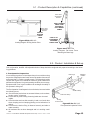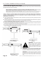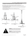
1
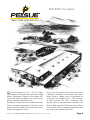
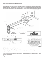
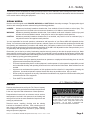
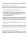
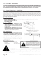
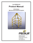
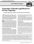
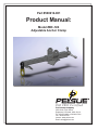
Part #500616-001
Product Manual:
Model #BC-14S
Adjustable Anchor Clamp
IS O 9 0 0 1 Ce r tifie d
T.A. Pelsue Company
2500 South Tejon Street
Englewood, Colorado, USA 80110
Tel. 800-525-8460 or 303-936-7432
Fax. 303-934-5581
Internet: www.pelsue.com
Email: [email protected]
Page 2
#500616-001 - Product Manual: Model #BC-14S Adjustable Anchor Clamp - Revision 01 - Date: 01-15-2009
IS O 9 0 0 1 Ce r tifie d
S
ince our inception in 1963 – the T.A. Pelsue
Company has designed and manufactured high
quality equipment to improve the personnel efficiency and working conditions in various underground, confined, and outdoor areas.
Founded by T. Allen Pelsue, the company has established a continuing reputation for excellence in the
production of fine products for a broad spectrum of
industry throughout the world.
Now, in our second generation of family direction,
continued commitment to innovation and quality
makes Pelsue a leading source of equipment for
many types of confined spaces. We specialize
in safety, retrieval, fall arrest, ventilation, cable
placing, splicing, and maintenance nationally and
abroad. With more than 70,000 square feet of facilities available, Pelsue continues the dedication that
has made us pre-eminent in this field.
#500616-001 - Product Manual: Model #BC-14S Adjustable Anchor Clamp - Revision 01 - Date: 01-15-2009
Page 3
Table of Contents
Section
Description
Page #
1.0......................................General Information..................................5
1.1...........................Quality Policy
1.2...........................Pelsue Product Warranty
2.0......................................Introduction & Product Information........7
2.1...........................Serial Number
3.0......................................Configuration & Assembly........................8
4.0......................................Safety..........................................................9
4.1...........................Warning Statement
4.2...........................Safety Alert Symbol
4.3...........................General Safety Information
4.4...........................Operating Safety
4.5...........................Maintenance Safety
4.6...........................New Operator Safety Information
5.0......................................Product Operation.....................................12
5.1...........................Product Description & Capabilities
5.2...........................Product Installation & Set-Up
6.0......................................Maintenance & Inspection........................16
6.1..........................Maintenance
6.2..........................Inspection
6.3...........................Inspection Log
7.0......................................Storage.......................................................19
8.0......................................Contact Information..................................19
Page 4
#500616-001 - Product Manual: Model #BC-14S Adjustable Anchor Clamp - Revision 01 - Date: 01-15-2009
1.0 General Information
1.1 Quality Policy
T.A. Pelsue Company
Quality Policy
OUR GOAL IS THE PURSUIT OF NEVER-ENDING IMPROVEMENT IN
PRODUCT QUALITY AND BUSINESS SYSTEMS.
Methods to be employed in attaining this goal will include
new product quality planning, employee training, and
utilization of employee involvement groups to solve
problems.
In an increasingly competitive marketplace, ensuring
customer satisfaction is one of the differentiators that
sets you apart from the pack and yields a competitive
advantage.
Therefore, we will support total customer satisfaction by
implementing the ISO 9001 Quality System and providing
the necessary atmosphere and training to nurture this
concept throughout our organization.
We will make every business decision as though the quality of
the part or service provided was destined for our own
or our family’s use. We will always think Quality First.
Every T.A. Pelsue Company employee is expected to commit to
this philosophy in the performance of his or her daily tasks.
QUALITY FIRST!
T.A. PELSUE COMPANY SENIOR MANAGEMENT TEAM
#500616-001 - Product Manual: Model #BC-14S Adjustable Anchor Clamp - Revision 01 - Date: 01-15-2009
Page 5
1.2 - Pelsue Product Warranty
Pelsue products are designed and engineered to perform as stated in published specifications.
Quality materials and workmanship are used in the manufacture of this product. With regular
maintenance and proper care, Pelsue equipment provides many trouble free hours of operation.
The T.A. Pelsue Company warrants to the buyer that the Hoist Product furnished will conform
to specifications and will be free from defects in material and workmanship from the date of
shipment to the original buyer, for a period of 3 months (90 days). In the event of failure of any
components of a Pelsue product within the warranty period, service must be pre-approved by
the T.A. Pelsue Company, and service must be performed by the T.A. Pelsue Parts and Service Department in Englewood, Colorado, or at the option of the T.A. Pelsue Company, service
may be performed at any designated service center, which may include any authorized service
center for the component manufacturer. Unauthorized repairs will not be covered by this warranty.
Damage or failure due to misuse, mishandling, or unauthorized modifications will not be covered
by this warranty. Unless otherwise agreed, the T.A. Pelsue Company shall repair or replace the
defective components within (30) calendar days of notice of failure. T.A. Pelsue Company’s
obligation hereunder, shall be limited to the repair or replacement of the product or component
as set forth above and shall not include any liability whatsoever for damages caused by such
failure, including, but not limited to consequential or incidental damages flowing from use or
lack of use of product.
Any replacement, repair, modification, installation, or other service performed by the T.A. Pelsue
Company shall be warranted by the remainder of the unexpired period of the warranty, or for a
period of (90) calendar days, whichever is longer.
All materials or parts returned for credit or warranty shall be returned only with prior approval,
and will be subject to factory inspection before credit is allowed, Parts claimed defective will
be replaced upon request and will be invoiced as purchased, subject to credit when the parts
claimed to be defective have been received and examined by the factory.
This warranty is expressly in lieu of all other warranties expressed or implied, including any
warranties of merchantability or warranties of fitness for any particular use and all other obligations or liabilities in connection with the sale of this equipment.
T.A. Pelsue Company, 2500 South Tejon Street, Englewood, Colorado 80110, 800-525-8460
Page 6
#500616-001 - Product Manual: Model #BC-14S Adjustable Anchor Clamp - Revision 01 - Date: 01-15-2009
2.0 - Introduction & Product Information
Congratulations on your choice of a Pelsue Model #BC-14S Adjustable Anchor Clamp to compliment your fall arrest
system. This equipment has been designed and manufactured to exceed fall arrest requirements and regulations in
order to meet the needs of the discriminating operator for the efficient and safe working conditions of personnel upon
an elevated working surface.
Safe, efficient and trouble-free operation and maintenance of the system requires that anyone who will be operating,
maintaining, or inspecting the equipment, read, understand and follow all the operation, safety, maintenance, and inspection instructions contained within this manual. This manual covers the Pelsue Model #BC-14S Adjustable Anchor Clamp.
Use the Table of Contents as a guide to find specific information.
Keep this manual handy for frequent reference and to pass on to new operators. Establish a regular training program
for experienced and new operators per this manual. Establish a regular maintenance and inspection program to keep
the equipment in top condition.
This product is a part of a complete Fall Arrest system.
The user must read, understand and follow the instructions contained in this manual for each component or
total system before using this equipment. Establish
an appropriate training, maintenance and inspection
program for your people and the equipment. Failure
to follow these instructions could result in serious
injury or death.
2.1 - Serial Number
Product Serial Number
Always give your dealer the serial number of your Pelsue Fall
Arrest product when ordering parts or requesting service or
other information.
The serial number decal is permanently embossed with a
serial number. The serial number decal will appear as shown
in Figure 2a at the right and is located on the side of the outer
tube (see Figure 2b). A space has been provided below for
the recording of the serial number for future reference.
#BC-14S
MODEL:____________________________________________
Serial Number :_______________________________________
Figure 2a:
Serial Number Decal
SERIAL
NUMBER
LOCATION
Date of Manufacture (DOM):____________________________
Figure 2b:
Serial Number Decal Location
#500616-001 - Product Manual: Model #BC-14S Adjustable Anchor Clamp - Revision 01 - Date: 01-15-2009
Page 7
3.0 - Configuration & Assembly
Upon initial receipt of the #BC-14S system, inspect the packaging for any evidence that the product may have been
damaged in shipment. While unpacking the product, inspect all of the components for damage. If damage to any of
the components is discovered, DO NOT USE THE PRODUCT! Alert the shipping carrier immediately of the damage
to the shipment.
CLAMPING HANDLE
BASE LUGS
BOLT
OUTER ANCHOR
CLAMP JAW
INNER ANCHOR
CLAMP JAW
D-RING
ANCHOR POINT
1
Figure 3b: #BC-14S
Parts Diagram
1) 102072-002
2
Figure 3b: #BC-14S
Label Location
Verify that all parts are present before product use.
The #BC-14S is shipped fully assembled.
2) 500234-001
1. Ensure that the product has been shipped with all the necessary components and is in working order
(Refer to Fig. #3b)
**Refer to parts list above if replacement parts are required. Replacement parts can be ordered from the T.A. Pelsue
Company at 800-525-8460.
Page 8
#500616-001 - Product Manual: Model #BC-14S Adjustable Anchor Clamp - Revision 01 - Date: 01-15-2009
4.0 - Safety
The following section will address the safety precautions which must be adhered to when working with Pelsue Fall Arrest
equipment such as the #BC-14S Adjustable Anchor Clamp. Any user must familiarize themselves with the information
in this section before utilizing the equipment.
SIGNAL WORDS:
Note the use of the signal words DANGER, WARNING and CAUTION with the safety messages. The appropriate signal
word for each message has been selected using the following guidelines:
DANGER-
Indicates an imminently hazardous situation that, if not avoided, will result in death or serious injury. This
signal word is to be limited to the most extreme situations or for hidden or unseen hazards.
WARNING- Indicates a potentially hazardous situation that, if not avoided, could result in death or serious injury and
includes obvious and hidden hazards. It may also be used to alert against unsafe practices.
CAUTION-
Indicates a potentially hazardous situation that, if not avoided, may result in minor or moderate injury. It
may also be used to alert against unsafe practices.
You are responsible for the safe operation, maintenance and inspection of your Pelsue #BC-14S Adjustable Anchor
Clamp. You must ensure that anyone who will operate, maintain, inspect or work around the equipment be familiar with
the operating and maintenance procedures and related safety information contained in this manual. This manual will
take you step-by-step through the workings and capabilities of the #BC-14S Adjustable Anchor Clamp and alert you to
all good safety and operating practices while using the system.
Remember, you are the key to safety. Good safety practices not only protect you but also the people around you. Make
these practices a working part of your safety program. Be certain that everyone operating this equipment is familiar with
the procedures recommended and follows safety precautions. Remember, most accidents can be prevented. Do not risk
injury or death by ignoring good safety practices.
•
System owners must give operating instructions to operators or employees before allowing them to use the
equipment and at least annually thereafter.
•
The most important safety device on this equipment is a safe operator. It is the operator’s responsibility to read
and understand all safety and operating instructions in the manual and to follow these. Most accidents can be
avoided.
•
A person must understand the operation of this equipment and be trained in it’s usage before operating the
equipment. An untrained operator exposes himself and others to possible serious injury or death.
•
Do not modify the equipment in any way. Unauthorized modification may impair the function and/or safety and
could affect the life of the equipment.
•
Think SAFETY! Work SAFELY!
4.1 - Warning Statement
WARNING!
Products manufactured or sold by the T.A. Pelsue Company
are intended for use by professionals trained and experienced
in the use, inspection and maintenance of these products.
Paraprofessional users such as volunteer rescue workers
and sportsmen involved in risk sports such as climbing and
caving will be held to the same standard of experience and
training as professionals.
Technical rescue, repelling, climbing and the training
involved are hazardous activities. Each situation has its
own unique conditions and must be evaluated. Effective
risk management comes from experience, proper training
and good personal judgement.
#500616-001 - Product Manual: Model #BC-14S Adjustable Anchor Clamp - Revision 01 - Date: 01-15-2009
!
WARNING
!
Failure to read and heed all labels and instructions may
result in injury or death. Inspect all components before
and after each use, and remove from service if any
damage or defect is found. Keep product free from dirt
and moisture.
Do not leave a suspended load
unattended. Do not exceed maximum rated loads.
Page 9
4.2 - Safety Alert Symbol
SAFETY ALERT SYMBOL
This Safety Alert symbol means ATTENTION! BECOME
ALERT! YOUR SAFETY IS INVOLVED!
The Safety Alert symbol identifies important safety messages
on your Pelsue Retrieval Product and in the manual. When
you see this symbol, be alert to the possibility of personal
injury or death. Follow the instruction in the safety message.
Why is this symbol important to you?
3 BIG Reasons:
Accidents Disable and Kill.
Accidents Cost You Money.
Accidents Can Be Avoided.
4.3 - General Safety Information
1. Read, understand, and follow the Product Manual and all safety signs before using, maintaining or inspecting the
equipment.
2. Refer to and follow applicable standards and regulations. Comply with requirements of local regulations for your
applications.
3. Establish an equipment-use training program for inexperienced employees. Only trained, competent persons shall
use the equipment. An untrained operator is not qualified to operate the system.
4. Have a first-aid kit available for use should the need arise and know how to use it.
5. Provide a fire extinguisher for use in case of an accident. Store in a highly visible place.
6. Install and properly secure all guards and shields before operating.
7. Wear appropriate protective gear. This list includes but is not limited to:
• A hard hat
• Protective shoes with slip resistant soles
• Heavy gloves
• Protective clothing
• Face Protection
8. Review and follow the Pre-Operation Checklist before using a component in the system or system itself.
9. Establish a regular maintenance and inspection program with your equipment and maintain detailed records.
10.Review safety related items and operating instructions with all personnel on a regular basis.
4.4 - Operating Safety
1.
Read, understand and follow the User Manual and signs on the product before using, maintaining or inspecting the equipment.
2.
Train all operators before allowing them to use the product. An untrained operator exposes themselves, bystanders
and workers to possible serious injury or death.
3.
Visually inspect the product and all auxiliary components and equipment before using. Correct any problems before
using the equipment.
4.
Securely anchor the product before using.
5.
Use only certified anchor and connector components in your system.
6.
Use only an approved full body harness for the workers.
Page 10
#500616-001 - Product Manual: Model #BC-14S Adjustable Anchor Clamp - Revision 01 - Date: 01-15-2009
4.4 - Operating Safety (continued)
7.
Always work in teams. One person is to work in the elevated space (entrant) and the other is to attend to the entrant
(attendant). Pelsue recommends an additional attendant/rescuer for stand-by in case of an emergency.
8.
Do not exceed the capacity of the system at any time (see section 5.1).
9.
Establish a regular training program for new and experienced workers.
10. Establish a detailed inspection program for your equipment and document the findings. Return the equipment to
the manufacturer for repair if any problems are found.
11. Plan your work program before starting. Have the required people, equipment and procedures available to do the
job.
12. Do not use the equipment around physical or environmental hazards. This list includes but is not limited to:
• Corrosion that may affect the structural integrity of the lifeline or other components.
• Chemicals which can degrade components in a manner which can not be visually identified.
• Toxic gases: Rescuers or workers can be killed in toxic environments.
• Heat or elevated temperatures.
• Moving machinery: Workers or auxiliary equipment can be contacted by or pulled into moving components.
• Sharp edges: Workers or the rescue equipment can be injured by or damaged by sharp edges or components.
• Electrical hazards: Stay away from power lines or components carrying electrical power.
• Overload: Do not overload the system at any time during operation (see section 5.1).
• Follow elevated space regulations and standards.
4.5 - Maintenance Safety
1. Read, understand and follow the User Manual and signs on the product before using, maintaining or inspecting the equipment.
2. ANSI and OSHA require a regular inspection program for all elevated fall arrest equipment and to maintain documented results of these inspections. Follow the inspection procedure contained in this manual and use the inspection
form to document the results (see section 6.0).
3.Keep instructional and safety signs clean and legible at all times. Clean or replace as required.
4. Remove the equipment from service if a problem is found during the inspection. Return to an authorized repair depot
or the factory for service.
4.6 - New Operator or Owner
The Pelsue #BC-14S Adjustable Anchor Clamp is designed as a portable Fall Arrest Anchor Point and Pelsue Fall Arrest
Tower Base System. Every new operator must read, understand and follow the instructions in the manual. No one
should be allowed to use the equipment without training. The training should be reviewed with experienced operators on
a regular basis. At regular intervals, perform a detailed inspection of the equipment and document the results. Remove
from service if deficiencies are found. Alterations or misuse of this equipment or failure to follow instructions may result
in serious injury or death.
It is the responsibility of the owner’s organization or operator to read this manual and to train all other operators before
they start working with the equipment. Follow all safety instructions exactly. Safety is everyone’s business. By following
recommended procedures, a safe working environment is provided for the operator, bystanders and the area around
the work site. Untrained operators are not qualified to operate the equipment.
Many features incorporated into this equipment are the result of suggestions made by customers like you. Read this
manual carefully to learn how to operate the equipment safely and how to set it to perform as intended. By following the
operating instructions in conjunction with a good maintenance program, your product will provide many years of trouble
free service.
#500616-001 - Product Manual: Model #BC-14S Adjustable Anchor Clamp - Revision 01 - Date: 01-15-2009
Page 11
5.0 - Product Operation
The following section will address the capabilities and the general operation of the Pelsue #BC-14S Adjustable Anchor
Clamp. The instructions contained within this section should be adhered to each and every time the product is used.
Any person tasked with installing or operating the piece of equipment should be familiar with these procedures.
5.1 - Product Description & Capabilities
The Pelsue #BC-14S Adjustable Anchor Clamp is built from carbon steel with steel hardware. The BC-14S Adjustable
Anchor Clamp is specifically designed to provide a portable fall arrest system anchor point and/or a mounting base for
a Pelsue Fall Arrest Tower. All specifications, instructions, and procedures provided within this manual or upon Pelsue
Specification Documents are based upon and only valid for usage with a Pelsue FT Series Fall Arrest Tower. The T.A.
Pelsue Company can not verify equipment safety and/or compliance when utilized with anything other than Pelsueapproved BC-14S complementary products.
General Specifications: Designed for clamping attachment on structural steel shapes commonly found in industrial locations.
• Minimum Clamped Section Width: 4”
• Maximum Clamped Section Width: 14”
• Product Weight: 31 lbs.
Compliance & Rating:
• D-Ring Anchor Point: Compliant as an anchorage for a fall arrest system for one person of 350 LBS
(159 KG.) maximum weight when utilized with a 900
LB. MAF Device.
• Fall Arrest Tower Mounting: The #BC-14S Base
Lugs provide a compliant mounting point for a Pelsue
FT Series Fall Arrest Tower when the tower is installed
and utilized per the published requirements.
Other Requirements:
Figure #5.1a: #BC-14S Installed on
a Typical Wide Flange Section
• It is the user’s responsibility to ensure that the structure to
which the #BC-14S is capable of withstanding the loads
imparted to it by a proof-loaded system in order to retain
stated compliance. *Refer to the loading diagrams located
within this section for required information*
• When utilized in conjunction with an FT Series Fall Arrest
Tower, the system must be employed according to the
requirements and limitations of both the anchor clamp and
the fall arrest tower.
Materials & Construction
• Main Structure
• Hardware
• Clamping Screw
- A36 Steel
- Plated Steel
- SAE Grade 2 Rod
The load ratings presented here may supersede or be superseded by the capabilities of
an installed accessory. The rating of a complete fall arrest system can only be rated to the
capabilities of its lowest-rated component.
! CAUTION ! - The user must ensure that the beam or structure that the #BC-14S is secured
must be capable of withstanding all of the loads imparted to it by the device when proof-loaded.
! CAUTION ! - The user must ensure that the bolt and pins are locked in place in order to retain the stated
compliance of the entire system.
Page 12
#500616-001 - Product Manual: Model #BC-14S Adjustable Anchor Clamp - Revision 01 - Date: 01-15-2009
5.1 - Product Description & Capabilities (continued)
TEST LOAD
APPLIED AS
SHOWN
TEST LOAD
APPLIED AS
SHOWN
5400 LB.
[2449 KG]
PROOF
LOAD
Figure #5.1b: #BC-14S
Loading Diagram: D-Ring Anchor Point
STATIC TENSILE
PROOF LOAD
APPLIED TO
FALL ARREST
TOWER
5458 FT.-LB.
EQUIVALENT
TORSIONAL
PROOF LOAD
Figure #5.1c: #BC-14S
Loading Diagram: Fall Arrest Tower
Mounting via Base Lugs
5.2 - Product Installation & Set-up
Prior to Operation, the #BC-14S Adjustable Anchor Clamp should be configured and prepared according to the following guidelines.
1. Pre-Operation Inspection:
It is necessary to perform a visual inspection prior to each time using
the product. If deficiencies are found, remove the product from service
and contact the T.A. Pelsue. regarding repair. The following checklist
coupled with Figure #5.2a should be used as a guide to determine
whether the equipment is in good operating condition prior to usage.
Equipment that is not in good condition can endanger the safety of
the operator’s during use.
The Pre-Operation Visual Inspection is not limited to, but must include
the following items;
a. Check that the product has no structural defects, such as dents,
bends, cracks, or fractures.
b. Ensure that all product rating & warning labels are clear and legible.
c. Check that the sections slide smoothly in and out of each other
when clamping and un-clamping (binding can be indicative of a
defect).
d. Check that the Anchor Ring is fastened securely and able to
rotate smoothly.
e. All hardware has not been damaged and is in working condition.
#500616-001 - Product Manual: Model #BC-14S Adjustable Anchor Clamp - Revision 01 - Date: 01-15-2009
Clamping
Handle
Base Lugs
Pin
Anchor Clamp
Anchor Clamp
D-Ring
Anchor Point
Figure #5.2a: #BC-14S
Pre-Operation Inspection Points
Page 13
5.2 - Product Installation & Set-up (continued)
2. Setup of #BC-14S Adjustable Anchor Clamp:
Choose a location where installation will provide suitable proximity to the work area yet minimize obstructions during
use and in the event a rescue is necessary.
•When utilized as an anchorage for a fall arrest system via the D-Ring Anchor Point: The safest installation places the D-Ring connection at approximately the height of the anchored user’s shoulders.
•When utilized as a Fall Arrest Tower Anchorage: Install The clamp so that the tower to be utilized will clear
all obstructions yet provide full access to all required work areas within the towers’s safe working radius.
*Once a location is chosen, Ensure that the structure to which the clamp will be attached is
capable of withstanding all of the forces imparted to it by the loaded device (Refer to the Loading Diagram in Section 5.1).
a. Turn the Clamping Handle counterclockwise in order to extend the inner tube from the outer tube and pull the outer
tubing (Refer to Fig. #5.2b).
b. Continue extending the Anchor Clamp until a point at which the desired installation flange will between the edges of
the two clamping jaws, and place the device onto the structure (Refer to Fig. #5.2c).
c. After the clamp has been placed on the structure, ensure that the jaws will fit around the structure and will be able
to clamp around the flange unobstructed (Refer to Fig. #5.2c).
d. Push the outer tube jaw adjacent to the flange, and then turn the Clamping Handle clockwise to retract the inner tube
jaw thereby clamping the device onto the structure (Refer to Fig. #5.2c).
e. The Clamping Handle should be tightened sufficiently with both hands so as to prevent movement of the device
along the structure when loaded (Refer to Fig. #5.2d).
Figure #5.2b: #BC-14S
Pre - Installation
Figure #5.2c: #BC-14S
Installation
!WARNING! - It is the user’s responsibility to ensure that the structure
to which the #BC-14S is attached is
capable of withstanding the #BC-14S’s
reported proof loads for safe installation.
!WARNING! - The user must ensure that the #BC-14S is
securely clamped on the selected structure before attaching
any lifeline or additional fall arrest system components.
Page 14
Figure #5.2d: #BC-14S
Completely Installed
!WARNING! - Any lifeline attached to the #BC-14S D-Ring
Anchor Point must utilize a 900 LB. MAF fall arrest device.
No lifeline may be attached top the #BC-14S tower base
lugs.
#500616-001 - Product Manual: Model #BC-14S Adjustable Anchor Clamp - Revision 01 - Date: 01-15-2009
5.2 - Product Installation & Set-up (continued)
3. Installation of an FT Series Fall Arrest Tower on the #BC-14S Anchor Clamp
a. Install the #BC-14S Anchor Clamp per the instructions in Step #2 on the previous page.
b. After the #BC-14S has been completely installed, remove the pin from the base of the fall arrest tower.
c. Place the fall arrest tower onto the #BC-14S, center the base of the tower between the two base lugs present on
the anchor clamp (Refer to Fig. 5.2e).
d. Align the holes of the fall arrest tower base with the holes of the base lugs on the #BC-14S and replace the pin
from the tower (Refer to Fig. 5.2f).
e. Adjust the levelling pegs in order to place the tower vertically (Refer to Fig. 5.2f).
f. Utilize the installed fall arrest tower within the limits of and according to the instructions provided within the FT
Series tower product manual.
LEVELING
PEGS
HITCH PIN
BASE LUGS
Figure #5.2e: #BC-14S & FT-C70
Installation
Figure #5.2f: #BC-14S & FT-C70
Installation
Figure #5.2g: #BC-14S & FT-C70
Completely Installed
!WARNING! - Any FT Series Fall Arrest Tower utilized
in conjunction with the #BC-14S Anchor Clamp must be
installed according to its product manual, and utilized by a
qualified individual in order to be a safe fall arrest system.
!WARNING! - Any FT Series Fall Arrest Tower Attached
to the #BC-14S Anchor Clamp must be utilized within its
published limits and capabilities. The rating of the installed
tower may superseded or derate the capabilities
#500616-001 - Product Manual: Model #BC-14S Adjustable Anchor Clamp - Revision 01 - Date: 01-15-2009
Page 15
6.0 - Maintenance & Inspection
MAINTENANCE & INSPECTION
1.
2.
Read, understand and follow the Product Manual and signs 3.Keep instructional and safety signs clean and legible at
on the product before using, maintaining or inspecting the
all times. Clean or replace as required.
equipment.
4. Remove the equipment from service if a problem is found
ANSI and OSHA require a regular inspection program for
during the inspection. Return to an authorized repair depot
all elevated fall arrest equipment and to maintain docuor the factory for service.
mented results of these inspections. Follow the inspection
procedure contained in this manual and use the inspection
form to document the results.
6.1 - Maintenance
For the most part, the Model #BC-14S is intended to be a maintenance-free piece of equipment, however several steps
can be taken to keep the system in top-notch working order and also extend the working life of the product.
Before Each Use:
1. V
isual Inspection: Perform a complete visual inspection. Refer to section 6.2 for guidelines and take any
maintenance steps that are necessary.
Annually:
1. C
lean Product: Use a damp cloth and mild soap to clean the structure and labels of dirt and residue. Be sure
the labels are legible (replacements are available from Pelsue)
2. C
omplete Inspection: Perform a thorough inspection, paying attention to the bullet points provided within
section 6.2. Record results and keep documentation. A log has been provided in section 6.3 specifically for
the recording of the dates & results of annual system inspections.
Periodic Factory Service Inspection: It is recommended that the product be serviced by a factory authorized
service center or the manufacturer after a period of three years. Extreme working conditions may indicate
the necessity to increase the frequency. Factory servicing shall include but not be limited to an intensive
inspection and cleaning of all internal and external components. Failure to provide proper service may shorten
product life and could endanger performance or function.
6.2 - Inspection
When completing an inspection of the Model #BC-14S Adjustable Anchor Clamp, the following specific items should be
checked;
1. Labels:
Check that all the labels are clean and legible (Refer to Section 3.0). Clean the labels if any are dirty using mild
soap and a damp cloth. Replace if any are illegible. Decals & labels provide valuable warning and caution information applicable to product usage and limitations, and should be visible and present at all times.
2. Anchor Point:
Ensure that the anchor point is securely fastened and that there are no loose parts. Also, visually inspect for any
fracture or deformation. Overloading of the system can and will deform and damage the D-Ring Anchor Point.
Any Model #BC-14S system exhibiting deformation should be removed from service immediately.
3. Structure:
The entire product structure should be checked for cracks, gouges, dents, bends or breaks. If there are major dents
or any other structural damage, the unit should be removed from service and returned to the factory for repair.
• Pay special attention to weld locations: look for cracks or separation at the welds. Keep in mind the zinc plat-
Page 16
#500616-001 - Product Manual: Model #BC-14S Adjustable Anchor Clamp - Revision 01 - Date: 01-15-2009
6.2 - Inspection (continued)
ing can age and scratch, this normal finish scratching can be confused with structural cracking. If there is any
uncertainty with regards to cracks, contact the Pelsue service department for assistance and/or recommendations
• Ensure that the two sections of the device can move in and out of each other without obstructions.
4. Clamping Mechanism:
Ensure that the clamping knob extends and retracts the clamp easily and without any binding. If some binding is
evident, It may be possible to apply spray lubricant onto the threads of the clamping rod through the inspection
hole in the weldment. If after applying lubricant, the clamping structure continuous to bind, remove the product
form service immediately. Binding or sticking of the clamping mechanism may be indicative of other structural
damage.
#500616-001 - Product Manual: Model #BC-14S Adjustable Anchor Clamp - Revision 01 - Date: 01-15-2009
Page 17
Page 18
#BC-14S
Inspector (print & sign) :
Inspector (print & sign) :
Inspector (print & sign) :
Inspector (print & sign) :
Inspector (print & sign) :
Inspector (print & sign) :
Inspector (print & sign) :
Inspector (print & sign) :
Date
labels
Anchor Point
Structure
Clamping
Mechanism
Place a check (√) in the box if item is acceptable, place an x (X) in the box if item requires maintenance or repair
Model Number :
Serial Number :
Date Purchased :
Notes
6.3 - Inspection Log
#500616-001 - Product Manual: Model #BC-14S Adjustable Anchor Clamp - Revision 01 - Date: 01-15-2009
7.0 - Storage
Prior to storage, the product should be thoroughly inspected and maintained. Repair or replace any worn or damaged
components to prevent any unnecessary down time at the next use.
Follow this procedure:
1. Thoroughly clean the entire unit using a mild soap on the frame and labels.
2. Perform a complete inspection of the unit and document the results prior to storage.
8.0 - Contact Information
For More Information...
T.A. Pelsue Company
2500 S. Tejon St.
Englewood, CO 80110
Toll Free:
Telephone:
Fax:
1-800-525-8460
1-303-936-7432
1-303-934-5581
Website:
www.pelsue.com
Email:
[email protected]
#500616-001 - Product Manual: Model #BC-14S Adjustable Anchor Clamp - Revision 01 - Date: 01-15-2009
Page 19
ISO 90 0 1 C e rt i f i e d
T.A. Pelsue Company
2500 South Tejon Street, Englewood, Colorado, USA 80110
Toll free 800-525-8460 or 303-936-7432 Fax. 303-934-5581
Internet: www.pelsue.com Email: [email protected]