1
Synplicity’s HAPS Development Platform
IP Core User’s Manual
Based on GRLIB
Sandi Habinc, Nils-Johan Wessman
Copyright Gaisler Research, May 2008.
2
Table of contents
1
Introduction.............................................................................................................................. 5
1.1
1.2
1.3
1.4
1.5
1.6
2
FLASH_1X1 - 32/16-bit PROM Controller for HAPS FLASH_1x1...................................... 7
2.1
2.2
2.3
2.4
2.5
3
Overview ............................................................................................................................................... 11
Operation ............................................................................................................................................... 11
Core usage ............................................................................................................................................. 12
Registers ................................................................................................................................................ 12
Vendor and device identifiers ................................................................................................................ 13
Configuration options............................................................................................................................ 13
Signal descriptions ................................................................................................................................ 13
Library dependencies ............................................................................................................................ 13
Component declaration.......................................................................................................................... 14
Instantiation ........................................................................................................................................... 14
HAPSTRAK - HapsTrak controller for HAPS boards .......................................................... 15
5.1
5.2
5.3
5.4
5.5
5.6
5.7
5.8
5.9
5.10
6
Overview ................................................................................................................................................. 9
Vendor and device identifier.................................................................................................................... 9
Library dependencies .............................................................................................................................. 9
Component declaration.......................................................................................................................... 10
Instantiation ........................................................................................................................................... 10
TEST_1X2 - Controller for HAPS test daughter board TEST_1x2 ...................................... 11
4.1
4.2
4.3
4.4
4.5
4.6
4.7
4.8
4.9
4.10
5
Overview ................................................................................................................................................. 7
Vendor and device identifier.................................................................................................................... 7
Library dependencies .............................................................................................................................. 7
Component declaration............................................................................................................................ 8
Instantiation ............................................................................................................................................. 8
SRAM_1X1 - 32-bit SSRAM / PROM Controller for HAPS SRAM_1x1............................. 9
3.1
3.2
3.3
3.4
3.5
4
Overview ................................................................................................................................................. 5
IP cores for HAPS development suite..................................................................................................... 5
Implementation characteristics................................................................................................................ 5
Licensing ................................................................................................................................................. 6
References ............................................................................................................................................... 6
About Synplicity...................................................................................................................................... 6
Overview ............................................................................................................................................... 15
Operation ............................................................................................................................................... 15
Core usage ............................................................................................................................................. 16
Registers ................................................................................................................................................ 16
Vendor and device identifiers ................................................................................................................ 19
Configuration options............................................................................................................................ 19
Signal descriptions ................................................................................................................................ 20
Library dependencies ............................................................................................................................ 20
Component declaration.......................................................................................................................... 20
Instantiation ........................................................................................................................................... 20
BIO1 - Controller for HAPS Basic I/O daughter board BIO1............................................... 22
6.1
6.2
6.3
6.4
Overview ............................................................................................................................................... 22
Operation ............................................................................................................................................... 22
Core usage ............................................................................................................................................. 23
Registers ................................................................................................................................................ 23
3
6.5
6.6
6.7
6.8
6.9
6.10
7
SDRAM_1X1 - Dual 32-bit PCI133 SDRAM Controller for HAPS SDRAM_1x1............. 27
7.1
7.2
7.3
7.4
7.5
8
Overview ............................................................................................................................................... 45
Configuration......................................................................................................................................... 46
Cores...................................................................................................................................................... 47
Interrupts ............................................................................................................................................... 47
Memory map ......................................................................................................................................... 48
LEON3 template design for HAPS-52 motherboard ............................................................. 49
12.1
12.2
12.3
12.4
12.5
13
Overview ............................................................................................................................................... 40
Configuration......................................................................................................................................... 41
Cores...................................................................................................................................................... 42
Interrupts ............................................................................................................................................... 42
Memory map ......................................................................................................................................... 43
Setup...................................................................................................................................................... 43
LEON3 template design for HAPS-51 motherboard ............................................................. 45
11.1
11.2
11.3
11.4
11.5
12
Overview ............................................................................................................................................... 33
Vendor and device identifier.................................................................................................................. 33
Configuration options............................................................................................................................ 34
Library dependencies ............................................................................................................................ 34
Component declaration.......................................................................................................................... 34
Instantiation ........................................................................................................................................... 35
HapsMap file for HapsTrak controller .................................................................................................. 37
LEON3 template design for HAPS-31 motherboard ............................................................. 40
10.1
10.2
10.3
10.4
10.5
10.6
11
Overview ............................................................................................................................................... 30
Vendor and device identifier.................................................................................................................. 30
Library dependencies ............................................................................................................................ 30
Component declaration.......................................................................................................................... 31
Instantiation ........................................................................................................................................... 31
GEPHY_1X1 - Ethernet Media Access Controller for HAPS GEPHY_1x1 ........................ 33
9.1
9.2
9.3
9.4
9.5
9.6
9.7
10
Overview ............................................................................................................................................... 27
Vendor and device identifier.................................................................................................................. 27
Library dependencies ............................................................................................................................ 27
Component declaration.......................................................................................................................... 27
Instantiation ........................................................................................................................................... 28
DDR_1X1 - DDR266 Controller for HAPS DDR_1x1......................................................... 30
8.1
8.2
8.3
8.4
8.5
9
Vendor and device identifiers ................................................................................................................ 24
Configuration options............................................................................................................................ 24
Signal descriptions ................................................................................................................................ 25
Library dependencies ............................................................................................................................ 25
Component declaration.......................................................................................................................... 25
Instantiation ........................................................................................................................................... 26
Overview ............................................................................................................................................... 49
Configuration......................................................................................................................................... 50
Cores...................................................................................................................................................... 51
Interrupts ............................................................................................................................................... 51
Memory map ......................................................................................................................................... 52
LEON3 template design for HAPS-54 motherboard ............................................................. 53
13.1
Overview ............................................................................................................................................... 53
4
13.2
13.3
13.4
13.5
14
Configuration......................................................................................................................................... 54
Cores...................................................................................................................................................... 55
Interrupts ............................................................................................................................................... 55
Memory map ......................................................................................................................................... 56
Application note for HAPS-50 motherboard demonstration ................................................. 57
14.1
14.2
14.3
14.4
14.5
14.6
14.7
14.8
14.9
Overview ............................................................................................................................................... 57
Hardware requirements ......................................................................................................................... 57
Software requirements........................................................................................................................... 58
Downloads............................................................................................................................................. 58
Software installation.............................................................................................................................. 58
Hardware setup...................................................................................................................................... 59
14.6.1 Setting up the HAPS-51 motherboard .................................................................................... 59
14.6.2 Setting up the HAPS-52 motherboard .................................................................................... 59
14.6.3 Setting up the HAPS-54 motherboard .................................................................................... 60
Software setup ....................................................................................................................................... 61
Compilation (optional) .......................................................................................................................... 61
Alternative software (optional) ............................................................................................................. 62
5
1
Introduction
1.1
Overview
Gaisler Research provides system-on-a-chip (SoC) solutions for exceptionally competitive markets
such as aerospace, military and demanding commercial applications. Gaisler Research's products consist of usercustomizable 32-bit SPARC V8 processor cores, peripheral IP-cores and associated software and development tools. The key product is the LEON3 32-bit SPARC processor core (LEON3).
LEON3 is a synthesisable VHDL model of a 32-bit processor compliant with the SPARC V8 architecture. The model is highly configurable, and particularly suitable for system-on-a-chip (SOC) designs.
The full source code is available under the GNU GPL license, allowing free and unlimited use for
research and education. LEON3 is also available under a low-cost commercial license, allowing it to
be used in any commercial application to a fraction of the cost of comparable IP cores.
Synplicity Hardware Platforms Group (www.synplicity.com) is a leading provider of off-the-shelf
ASIC prototyping boards. The key product is HAPS™ (High-performance ASIC Prototyping System), a modular system with multi-FPGA motherboards and standard or custom-made daughter
boards which can be stacked together in a variety of ways.
Gaisler Research's GRLIB IP library environment includes support for HAPS™ development platforms, providing example designs and board support packages used with Synplicity's synthesis tools
and Xilinx’ place & route tools.
Gaisler Research's HAPS™ development suite comprises everything needed in order to develop a
LEON3 based system-on-a-chip design for a HAPS™ platform. The suite includes:
1.2
•
GRLIB VHDL IP library, containing LEON3 source code, HAPS™ specific IP cores etc.
•
Synplicity HAPS™ template designs (HAPS-31, HAPS-51, HAPS-52, HAPS-54 etc.)
•
Bare-C Cross-compiler system (BCC)
•
GRMON debug monitor software
IP cores for HAPS development suite
The IP cores cover the following functions:
1.3
•
FLASH_1X1
32/16-bit PROM Controller for HAPS™ FLASH_1x1
•
SRAM_1X1
32-bit SSRAM / PROM Controller for HAPS™ SRAM_1x1
•
TEST_1X2
Controller for HAPS™ test daughter board TEST_1x2
•
HAPSTRAK
HapsTrak controller for HAPS™ boards
•
BIO1
Controller for HAPS™ test daughter board BIO1
•
SDRAM_1X1
32-bit SDRAM Controller for HAPS™ SDRAM_1x1
•
DDR_1X1
DDR266 Controller for HAPS™ DDR_1x1
•
GEPHY_1X1
Ethernet Controller for HAPS™ GEPHY_1x1
Implementation characteristics
The cores are portable and can be implemented on most FPGA and ASIC technologies, and have been
tested for Xilinx Virtex-4 and Virtex-5 FPGA technologies. The cores are available in VHDL source
code and, when applicable, use the plug&play configuration method described in the ‘GRLIB IP
LIbrary User’s Manual’.
6
1.4
Licensing
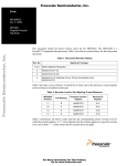
The tables below lists the provided IP cores and their AMBA plug&play device ID. The license column indicates if a core is available under GNU GPL and/or under a commercial license (COM).
The open-source version of GRLIB includes only cores marked with GPL or LGPL.
Table 1. HAPS functions
Name
Function
Vendor:Device
License
FLASH_1X1
32/16-bit PROM Controller for HAPS FLASH_1x1
0x01 : 0x00A
COM *
SRAM_1X1
32-bit SSRAM / PROM Controller for HAPS SRAM_1x1
0x01 : 0x00A
COM *
TEST_1X2
Controller for HAPS test daughter board TEST_1x2
0x01 : 0x078
GPL
HAPSTRAK
HapsTrak controller for HAPS boards
0x01 : 0x077
GPL
BIO1
Controller for HAPS I/O board BIO1
0x01 : 0x07A
GPL
SDRAM_1X1
32-bit SDRAM Controller for HAPS SDRAM_1x1
0x01 : 0x009
GPL
DDR_1X1
64-bit DDR266 Controller for HAPS DDR_1x1
0x01 : 0x025
GPL
GEPHY_1X1
Ethernet Controller for HAPS GEPHY_1x1
0x01 : 0x00A
GPL **
Note*: The underlying SSRAM controller used in the FLASH_1X1 and SRAM_1X1 cores is provided in VHDL
netlist format in the GRLIB GPL distribution. The VHDL source code is only provided under commercial license.
Note**: The 10/100 Mbit Media Access Controller (MAC) is available in the GRLIB GPL distribution. The 1000 Mbit
MAC is only provided under commercial license.
1.5
References
[GRLIB]
GRLIB IP Library User’s Manual, Gaisler Research,
http://www.gaisler.com/products/grlib/grlib.pdf
[GRIP]
GRLIB IP Core User’s Manual, Gaisler Research
http://www.gaisler.com/products/grlib/grip.pdf
[GRMON]
GRMON User’s Manual, Gaisler Research
http://www.gaisler.com/doc/grmon.pdf
[SPARC]
1.6
The SPARC Architecture Manual, Version 8, Revision SAV080SI9308,
SPARC International Inc, http://www.sparc.org
About Synplicity
Synplicity ®, Inc. is a leading supplier of innovative IC design and verification solutions that serve a
wide range of communications, military/aerospace, semiconductor, consumer, computer, and other
electronic applications markets. Synplicity’s FPGA implementation tools provide outstanding performance, cost and time-to-market benefits by simplifying, improving and automating logic synthesis,
physical synthesis, analysis and debug for programmable logic designs.
The Confirma™ at-speed verification platform, comprising software tools and the HAPS™ family of
prototyping systems, enables both comprehensive verification of ASIC, ASSP and SoC designs and
software development prior to chip tapeout.
For more information about HAPS, visit http://www.synplicity.com.
Synplicity, the Synplicity logo, and “Simply Better Results” are registered trademarks of
Synplicity, Inc.
HAPS, the HAPS logo, “High-performance ASIC Prototyping System”, and HapsTrak, HapsTrak I
and HapsTrak II are trademarks of Synplicity, Inc.
7
2
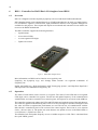
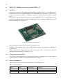
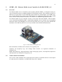
FLASH_1X1 - 32/16-bit PROM Controller for HAPS FLASH_1x1
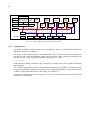
2.1
Overview
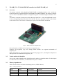
The memory controller for the Synplicity HAPS FLASH_1x1 daughter boards is a 32- / 16-bit controller that interfaces external PROM or Flash PROM to the AMBA AHB bus. The memory controller
acts as a slave on the AHB bus and has a configuration register accessible through an APB slave interface.
The memory controller is based on the Gaisler Research SSRCTRL - 32-bit SSRAM/PROM Controller. See corresponding manual for details. The SSCTRL IP core is provided in VHDL netlist format
for the Xilinx Virtex 4 and Virtex 5 technologies as part of the GRLIB GPL distribution.
Figure 1. HAPS FLASH_1x1 daughter board
More information on HAPS can be found at www.synplicity.com.
Synplicity, the Synplicity logo, and “Simply Better Results” are registered trademarks of
Synplicity, Inc.
HAPS, the HAPS logo, “High-performance ASIC Prototyping System”, and HapsTrak, HapsTrak I
and HapsTrak II are trademarks of Synplicity, Inc.
2.2
Vendor and device identifier
The core has vendor identifier 0x01 (Gaisler Research) and device identifier 0x00A. For description
of vendor and device identifiers, see GRLIB IP Library User’s Manual.
2.3
Library dependencies
Table 2 shows libraries used when instantiating the core (VHDL libraries).
Table 2. Library dependencies
Library
Package
Imported unit(s)
Description
GRLIB
AMBA
Signals
AMBA signal definitions
GAISLER
MEMCTRL
Signals
Signal declarations
GAISLER
HAPS
Component
Component declaration
8
2.4
Component declaration
The core has the following component declaration.
component flash_1x1 is
generic (
hindex:
integer := 0;
pindex:
integer := 0;
romaddr:
integer := 16#000#;
rommask:
integer := 16#E00#;
ioaddr:
integer := 16#200#;
iomask:
integer := 16#E00#;
ramaddr:
integer := 16#400#;
rammask:
integer := 16#C00#;
paddr:
integer := 0;
pmask:
integer := 16#fff#;
bus16:
integer := 0;
tech:
integer := 0;
netlist:
integer := 0);
port (
rst
: in std_ulogic;
clk
: in std_ulogic;
ahbsi
: in ahb_slv_in_type;
ahbso
: out ahb_slv_out_type;
apbi
: in apb_slv_in_type;
apbo
: out apb_slv_out_type;
sri
: in memory_in_type;
sro
: out memory_out_type);
end component;
2.5
Instantiation
This example shows how the core can be instantiated.
library grlib;
use grlib.amba.all;
library gaisler;
use gaisler.haps.all;
use gaisler.memctrl.all;
...
signal flash_memi : memory_in_type;
signal flash_memo : memory_out_type;
begin
flash_1x1_0 : if CFG_FLASH_1x1 = 1 generate
flash_1x1_0 : flash_1x1
generic map (
hindex => 3,
pindex => 0,
rommask => 16#f00#,
iomask => 0, -- no memory mapped IO
ramaddr => 0,
rammask => 0, -- no SSRAM memory
paddr => 4,
bus16 => CFG_FLASH_1x1_PROM16,
netlist => CFG_FLASH_1x1_NETLIST,
tech => virtex5)
port map (rstn, clkm, ahbsi, ahbso(3), apbi, apbo(0), flash_memi, flash_memo);
end generate;
...
9
3
SRAM_1X1 - 32-bit SSRAM / PROM Controller for HAPS SRAM_1x1
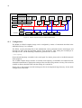
3.1
Overview
The memory controller for the Synplicity HAPS SRAM_1x1 daughter boards is a 32-bit SSRAM
controller that interfaces external synchronous pipelined SRAM to the AMBA AHB bus. It can also
interface 16- and 32-bit PROM or Flash PROM memory. The memory controller acts as a slave on the
AHB bus and has a configuration register accessible through an APB slave interface.
The memory controller is based on the Gaisler Research SSRCTRL - 32-bit SSRAM/PROM Controller. See corresponding manual for details. The SSCTRL IP core is provided in VHDL netlist format
for the Xilinx Virtex 4 and Virtex 5 technologies as part of the GRLIB GPL distribution.
The memory controller can also be used with the Synplicity HAPS-51 motherboard to interface the
synchronous pipelined SRAM and the Flash PROM memory.
Figure 2. HAPS SRAM_1x1 daughter board
More information on HAPS can be found at www.synplicity.com.
Synplicity, the Synplicity logo, and “Simply Better Results” are registered trademarks of
Synplicity, Inc.
HAPS, the HAPS logo, “High-performance ASIC Prototyping System”, and HapsTrak, HapsTrak I
and HapsTrak II are trademarks of Synplicity, Inc.
3.2
Vendor and device identifier
The core has vendor identifier 0x01 (Gaisler Research) and device identifier 0x00A. For description
of vendor and device identifiers, see GRLIB IP Library User’s Manual.
3.3
Library dependencies
Table 3 shows libraries used when instantiating the core (VHDL libraries).
Table 3. Library dependencies
Library
Package
Imported unit(s)
Description
GRLIB
AMBA
Signals
AMBA signal definitions
GAISLER
MEMCTRL
Signals
Signal declarations
GAISLER
HAPS
Component
Component declaration
10
3.4
Component declaration
The core has the following component declaration.
component sram_1x1
generic (
hindex:
pindex:
romaddr:
rommask:
ioaddr:
iomask:
ramaddr:
rammask:
paddr:
pmask:
bus16:
tech:
netlist:
port (
rst
: in
clk
: in
ahbsi
: in
ahbso
: out
apbi
: in
apbo
: out
sri
: in
sro
: out
end component;
3.5
is
integer
integer
integer
integer
integer
integer
integer
integer
integer
integer
integer
integer
integer
:=
:=
:=
:=
:=
:=
:=
:=
:=
:=
:=
:=
:=
0;
0;
16#000#;
16#E00#;
16#200#;
16#E00#;
16#400#;
16#C00#;
0;
16#fff#;
0;
0;
0);
std_ulogic;
std_ulogic;
ahb_slv_in_type;
ahb_slv_out_type;
apb_slv_in_type;
apb_slv_out_type;
memory_in_type;
memory_out_type);
Instantiation
This example shows how the core can be instantiated.
library grlib;
use grlib.amba.all;
library gaisler;
use gaisler.haps.all;
use gaisler.memctrl.all;
...
signal memi : memory_in_type;
signal memo : memory_out_type;
begin
ssr0 : if CFG_SRAM_1x1 = 1 generate
sram_1x1_0 : sram_1x1
generic map (
hindex => 5,
pindex => 4,
rommask => 0, -- no PROM memory
iomask => 0, -- no memory mapped IO
ramaddr => 16#400#,
bus16 =>CFG_SRAM_1x1_PROM16,
netlist => CFG_SRAM_1x1_NETLIST,
tech => virtex5)
port map (rstn, clkm, ahbsi, ahbso(5), apbi, apbo(4), memi, memo);
end generate;
...
11
4
TEST_1X2 - Controller for HAPS test daughter board TEST_1x2
4.1
Overview
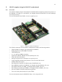
TEST_1x2 is a daughter board developed by Synplicity to be used with their HAPS motherboards.
TEST_1x2 daughter board can be attached directly to a HAPS motherboard to be used as a simple
interactive I/O interface. A number of LEDs, push buttons and an LCD are available for this purpose.
These inputs and outputs are monitored and controlled via one of the two HapsTrak connectors on the
board.
The TEST_1X2 controller supports the following functions:
•
12 push buttons
•
12 two-color LEDs
•
LCD with four 7-segment characters
•
LCD clock generation
Figure 3. HAPS TEST_1x2 daughter board
More information on HAPS can be found at www.synplicity.com.
Synplicity, the Synplicity logo, and “Simply Better Results” are registered trademarks of
Synplicity, Inc.
HAPS, the HAPS logo, “High-performance ASIC Prototyping System”, and HapsTrak, HapsTrak I
and HapsTrak II are trademarks of Synplicity, Inc.
4.2
Operation
The status of each button can be read out via a register.
The value of each LED can be controlled via a register.
The value of each LCD segment can be controlled via a register. The register output is modulated with
the LCD clock frequency.
The two LCD clocks are generated by the controller. The LCD clock oscillator frequency is generated
from the system clock and is configurable through the fdiv VHDL generic that defines the clock division factor.
12
4.3
Core usage
Note that the mapping between the VHDL ports and the TEST_1x2 daughter board depends on which
connectors on the motherboard it is connected to. HapsMap is a pin assignment software from Synplicity that generates Xilinx UCF files describing the mapping from RTL port names (VHDL or Verilog) to pins for all FPGAs in a HAPS system. For details, refer to the HAPS manuals from Synplicity.
The register mapping hereafter assumes the following mapping between the VHDL ports and the
names used by HapsMap, TEST_1x2 daughter board signal names and connector:
VHDL signals
HapsMap signals
TEST_1x2
Connector J2B
-----------------------------------------------------------------------------------test_1x2o.lcd_seg(0-31)
ctrl.lcd(0-31)
test_1x2o.lcd_clk(0-1)
ctrl.bp(1-2)
test_1x2o.green_led_n(0-11) ctrl.green_n(1-12) L[1:6]&SL[1:6] J2B[42:47]&J2B[36:41]
test_1x2o.red_led_n(0-11)
ctrl.red_n(1-12)
L[1:6]&SL[1:6] J2B[54:59]&J2B[48:53]
test_1x2i.button_n(0-11)
ctrl.button_n(1-12) S[1:6]&SL[1:6] J2B[24:29]&J2B[30:35]
4.4
Registers
The core is programmed through registers mapped into APB address space.
Table 4.
TEST_1X2 registers
APB address offset
Register
0x00
Buttons register
0x04
LCD register
0x08
LED register
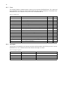
Table 5. Buttons register
31
12 11 10
“000..0”
11:
6
Buttons SL6 to SL1
5:
0
Buttons S6 to S1
9
8
7
6
5
4
3
2
1
0
SL SL SL SL SL SL S6 S5 S4 S3 S2 S1
6 5 4 3 2 1
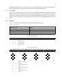
Table 6. LCD register
31 30 29 28 27 26 25 24 23 22 21 20 19 18 17 16 15 14 13 12 11 10
9
8
7
6
5
4
4A 4B 4C 4D 4E 4F 4G 3A 3B 3C 3D 3E 3F 3G 2A 2B 2C 2D 2E 2F 2G 1A 1B 1C 1D 1E 1F 1G
4A
4F
4G
3A
4B
3F
3G
2A
3B
L
2F
2G
3
2
1
4 3 2
DP DP DP
1A
2B
1F
1G
1B
:
4E
4C
3E
3C
*
4D
4DP
31:
25
Character 4
24:
18
Character 3
17:
11
Character 2
10:
4
2E
2C
*
3D
Character 1
3
4DP, fourth decimal point
2
3DP, third decimal point
1
2DP, second decimal point
0
L, colon
3DP
1E
1C
*
2D
2DP
1D
0
L
13
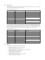
Table 7. LED register
31
24
23
“000..0”
4.5
13
L12
Red
...
23:
12
Red LEDs L12 to L1
11:
0
Green LEDs L12 to L1
12
11
L1
Red
L12
Green
10
1
...
0
L1
Green
Vendor and device identifiers
The core has vendor identifier 0x01 (Gaisler Research) and device identifier 0x078. For description of
vendor and device identifiers, see GRLIB IP Library User’s Manual.
4.6
Configuration options
Table 8 shows the configuration options of the core (VHDL generics).
Table 8. Configuration options
4.7
Generic
Function
Allowed range
Default
pindex
Selects which APB select signal (PSEL) will be used to
access the GPIO unit
0 to NAPBMAX-1
0
paddr
The 12-bit MSB APB address
0 to 16#FFF#
0
pmask
The APB address mask
0 to 16#FFF#
16#FFF#
fdiv
Defines division factor for generating LCD clock
Integer
1000000
Signal descriptions
Table 9 shows the interface signals of the core (VHDL ports).
Table 9. Signal descriptions
Signal name
Field
Type
Function
Active
RST
N/A
Input
Reset
Low
CLK
N/A
Input
Clock
-
APBI
*
Input
APB slave input signals
-
APBO
*
Output
APB slave output signals
-
TEST_1X2O
LCD_CLK[1:0]
Output
LCD clock output
-
LCD_SEG[31:0]
Output
LCD segment output
-
GREEN_LED_N[11:0]
Output
Green LEDs output
Low
RED_LED_N[11:0]
Output
Red LEDs output
Low
BUTTON_N[11:0]
Input
Buttons input
Low
TEST_1X2I
* see GRLIB IP Library User’s Manual
4.8
Library dependencies
Table 10 shows libraries used when instantiating the core (VHDL libraries).
Table 10. Library dependencies
Library
Package
Imported unit(s)
Description
GRLIB
AMBA
Signals
AMBA signal definitions
GAISLER
HAPS
Signals, component
Component declaration
14
4.9
Component declaration
The core has the following component declaration.
component test_1x2
generic (
pindex
:
paddr
:
pmask
:
fdiv
:
port (
rst
: in
clk
: in
apbi
: in
apbo
: out
test_1x2i
: in
test_1x2o
: out
end component;
4.10
integer
integer
integer
integer
:=
:=
:=
:=
0;
0;
16#fff#;
1000000);
std_logic;
std_logic;
apb_slv_in_type;
apb_slv_out_type;
test_1x2_in_type;
test_1x2_out_type);
Instantiation
This example shows how the core can be instantiated.
library grlib;
use grlib.amba.all;
library gaisler;
use gaisler.haps.all;
...
signal test_1x2i : test_1x2_in_type;
signal test_1x2o : test_1x2_out_type;
begin
test_1x2_gen : if CFG_TEST_1X2 /= 0 generate
test_1x2_inst : test_1x2
generic map(
pindex => 5,
paddr => 5,
fdiv => 1000000)
port map (
rst => rstn,
clk => clkm,
apbi => apbi,
apbo => apbo(5),
test_1x2i => test_1x2i,
test_1x2o => test_1x2o);
end generate;
...
15
5
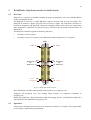
HAPSTRAK - HapsTrak controller for HAPS boards
5.1
Overview
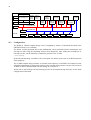
HapsTrak is a connector and module standard developed by Synplicity to be used with their HAPS
mother and daughter boards.
The HapsTrak I connector, or simply HapsTrak, supports 120 pins with 119 user I/O signals. The
HapsTrak II connector supports 128 pins with 119 user I/O signals. The HapsTrak II connector is
backwards compatible with HapsTrak I. HapsTrak I daughter boards will not loose any functionality
when mounted on a HapsTrak II connector, but they will not be able to benefit from the features of
HapsTrak II.
The HapsTrak controller supports the following functions:
•
119 inputs, read via registers
•
119 outputs, written via registers, with individually enabled output drivers via registers
GND
+3.3V H1
B1
A1
B30
Reserved H3
for
future use H5
B31
H2 +3.3V
A30
H4 Reserved
for
H6 future use
A31
B60
VCCO
VCCO H7
A60
H8 VCCO
GND
Figure 4. HapsTrak II connector pinout
More information on HAPS and HapsTrak can be found at www.synplicity.com.
Synplicity, the Synplicity logo, and “Simply Better Results” are registered trademarks of
Synplicity, Inc.
HAPS, the HAPS logo, “High-performance ASIC Prototyping System”, and HapsTrak, HapsTrak I
and HapsTrak II are trademarks of Synplicity, Inc.
5.2
Operation
Each signal on the HapsTrak connector can be read from or written to via registers. The output enable
of each signal is individually programmable.
16
5.3
Core usage
Note that the mapping between the VHDL ports of the HapsTrak controller and the HapsTrak I or
HapsTrak II pins depends on which connector on the motherboard it is connected to. For details,
please refer to the HAPS manuals from Synplicity.
The following is an example of a mapping between the HapsTrak controller ports (and registers), typical signal names for a top-level design and the HapsTrak II pin names.
hapstraki/hapstrako( 0)
<-> {unused}
hapstraki/hapstrako( 30 downto 1) <-> hapstraka(30: 1)
hapstraki/hapstrako( 31)
<-> {unused}
hapstraki/hapstrako( 32)
<-> {unused}
hapstraki/hapstrako( 62 downto 33) <-> hapstraka(60:31)
hapstraki/hapstrako( 63)
<-> {unused}
hapstraki/hapstrako( 64)
<-> {unused}
hapstraki/hapstrako( 94 downto 65) <-> hapstrakb(30: 1)
hapstraki/hapstrako( 95)
<-> {unused}
hapstraki/hapstrako( 96)
<-> {unused}
hapstraki/hapstrako(125 downto 97) <-> hapstrakb(59:31)
hapstraki/hapstrako(126)
<-> {unused}
hapstraki/hapstrako(127)
<-> {unused}
5.4
<->
<->
<->
<->
<->
<->
<->
<->
<->
<->
<->
<->
<->
H2
A30
H4
H6
A60
H8
H1
B30
H3
H5
B59
B60
H7
downto A1
downto A31
downto B1
downto B31
Registers
The core is programmed through registers mapped into APB address space.
Table 11. HAPSTRAK registers
APB address offset
Register
0x00 - 0x0C
Input registers
0x10 - 0x1C
Output registers
0x20 - 0x2C
Output enable registers
17
Table 12. Input register 0
31 30 29 28 27 26 25 24 23 22 21 20 19 18 17 16 15 14 13 12 11 10
31 30
-
9
8
7
6
5
4
3
2
HapsTrak
A A A A A A A A A A A A A A A A A A A A A
30 29 28 27 26 25 24 23 22 21 20 19 18 17 16 15 14 13 12 11 10
31
30:
A
9
A
8
A
7
A
6
A
5
A
4
A
3
A
2
9
8
7
6
5
4
3
2
1
0
1
0
A
1
-
1
0
HapsTrak (31) input, unused
1
0
HapsTrak (30:1) input, (a.k.a. hapstraka(30:1))
HapsTrak (0) input, unused
Table 13. Input register 1
31 30 29 28 27 26 25 24 23 22 21 20 19 18 17 16 15 14 13 12 11 10
63 62
-
HapsTrak
33 32
A A A A A A A A A A A A A A A A A A A A A A A A A A A A A A
60 59 58 57 56 55 54 53 52 51 50 49 48 47 46 45 44 43 42 41 40 39 38 37 36 35 34 33 32 31
31
30:
-
HapsTrak (63) input, unused
1
0
HapsTrak (62:33) input, (a.k.a. hapstraka(60:31))
HapsTrak (32) input, unused
Table 14. Input register 2
31 30 29 28 27 26 25 24 23 22 21 20 19 18 17 16 15 14 13 12 11 10
95 94
-
9
8
7
6
5
4
3
2
HapsTrak
B B B B B B B B B B B B B B B B B B B B B
30 29 28 27 26 25 24 23 22 21 20 19 18 17 16 15 14 13 12 11 10
31
30:
1
0
65 64
B
9
B
8
B
7
B
6
B
5
B
4
B
3
B
2
9
8
7
6
5
4
3
2
B
1
-
1
0
HapsTrak (95) input, unused
1
0
HapsTrak (94:65) input, (a.k.a. hapstrakb(30:1))
HapsTrak (64) input, unused
Table 15. Input register 3
31 30 29 28 27 26 25 24 23 22 21 20 19 18 17 16 15 14 13 12 11 10
127 126 125
-
-
HapsTrak
97 96
B B B B B B B B B B B B B B B B B B B B B B B B B B B B B
59 58 57 56 55 54 53 52 51 50 49 48 47 46 45 44 43 42 41 40 39 38 37 36 35 34 33 32 31
31
HapsTrak (127) input, unused
30
HapsTrak (126) input, unused
29:
0
1
HapsTrak (125:97) input, (a.k.a. hapstrakb(60:31))
HapsTrak (96) input, unused
-
18
Table 16. Output register 0
31 30 29 28 27 26 25 24 23 22 21 20 19 18 17 16 15 14 13 12 11 10
31 30
-
9
8
7
6
5
4
3
2
HapsTrak
A A A A A A A A A A A A A A A A A A A A A
30 29 28 27 26 25 24 23 22 21 20 19 18 17 16 15 14 13 12 11 10
31
30:
A
9
A
8
A
7
A
6
A
5
A
4
A
3
A
2
9
8
7
6
5
4
3
2
1
0
1
0
A
1
-
1
0
HapsTrak (31) output, unused
1
0
HapsTrak (30:1) output, (a.k.a. hapstraka(30:1))
HapsTrak (0) output, unused
Table 17. Output register 1
31 30 29 28 27 26 25 24 23 22 21 20 19 18 17 16 15 14 13 12 11 10
63 62
-
HapsTrak
33 32
A A A A A A A A A A A A A A A A A A A A A A A A A A A A A A
60 59 58 57 56 55 54 53 52 51 50 49 48 47 46 45 44 43 42 41 40 39 38 37 36 35 34 33 32 31
31
30:
-
HapsTrak (63) output, unused
1
0
HapsTrak (62:33) output, (a.k.a. hapstraka(60:31))
HapsTrak (32) output, unused
Table 18. Output register 2
31 30 29 28 27 26 25 24 23 22 21 20 19 18 17 16 15 14 13 12 11 10
95 94
-
9
8
7
6
5
4
3
2
HapsTrak
B B B B B B B B B B B B B B B B B B B B B
30 29 28 27 26 25 24 23 22 21 20 19 18 17 16 15 14 13 12 11 10
31
30:
1
0
65 64
B
9
B
8
B
7
B
6
B
5
B
4
B
3
B
2
9
8
7
6
5
4
3
2
B
1
-
1
0
HapsTrak (95) output, unused
1
0
HapsTrak (94:65) output, (a.k.a. hapstrakb(30:1))
HapsTrak (64) output, unused
Table 19. Output register 3
31 30 29 28 27 26 25 24 23 22 21 20 19 18 17 16 15 14 13 12 11 10
127 126 125
-
-
HapsTrak
97 96
B B B B B B B B B B B B B B B B B B B B B B B B B B B B B
59 58 57 56 55 54 53 52 51 50 49 48 47 46 45 44 43 42 41 40 39 38 37 36 35 34 33 32 31
31
HapsTrak (127) output, unused
30
HapsTrak (126) output, unused
29:
0
1
HapsTrak (125:97) output, (a.k.a. hapstrakb(60:31))
HapsTrak (96) output, unused
-
19
Table 20. Output Enable register 0
31 30 29 28 27 26 25 24 23 22 21 20 19 18 17 16 15 14 13 12 11 10
31 30
-
9
8
7
6
5
4
3
2
HapsTrak
A A A A A A A A A A A A A A A A A A A A A
30 29 28 27 26 25 24 23 22 21 20 19 18 17 16 15 14 13 12 11 10
31
30:
A
9
A
8
A
7
A
6
A
5
A
4
A
3
A
2
9
8
7
6
5
4
3
2
1
0
1
0
A
1
-
1
0
HapsTrak (31) output enable, unused
1
0
HapsTrak (30:1) output enable, (a.k.a. hapstraka(30:1))
HapsTrak (0) output enable, unused
Table 21. Output Enable register 1
31 30 29 28 27 26 25 24 23 22 21 20 19 18 17 16 15 14 13 12 11 10
63 62
-
HapsTrak
33 32
A A A A A A A A A A A A A A A A A A A A A A A A A A A A A A
60 59 58 57 56 55 54 53 52 51 50 49 48 47 46 45 44 43 42 41 40 39 38 37 36 35 34 33 32 31
31
30:
-
HapsTrak (63) output enable, unused
1
0
HapsTrak (62:33) output enable, (a.k.a. hapstraka(60:31))
HapsTrak (32) output enable, unused
Table 22. Output Enable register 2
31 30 29 28 27 26 25 24 23 22 21 20 19 18 17 16 15 14 13 12 11 10
95 94
-
9
8
7
6
5
4
3
2
HapsTrak
B B B B B B B B B B B B B B B B B B B B B
30 29 28 27 26 25 24 23 22 21 20 19 18 17 16 15 14 13 12 11 10
31
30:
1
0
65 64
B
9
B
8
B
7
B
6
B
5
B
4
B
3
B
2
9
8
7
6
5
4
3
2
B
1
-
1
0
HapsTrak (95) output enable, unused
1
0
HapsTrak (94:65) output enable, (a.k.a. hapstrakb(30:1))
HapsTrak (64) output enable, unused
Table 23. Output Enable register 3
31 30 29 28 27 26 25 24 23 22 21 20 19 18 17 16 15 14 13 12 11 10
127 126 125
-
-
97 96
B B B B B B B B B B B B B B B B B B B B B B B B B B B B B
59 58 57 56 55 54 53 52 51 50 49 48 47 46 45 44 43 42 41 40 39 38 37 36 35 34 33 32 31
31
HapsTrak (127) output enable, unused
30
HapsTrak (126) output enable, unused
29:
0
5.5
HapsTrak
1
-
HapsTrak (125:97) output enable, (a.k.a. hapstrakb(60:31))
HapsTrak (96) output enable, unused
Vendor and device identifiers
The core has vendor identifier 0x01 (Gaisler Research) and device identifier 0x077. For description of
vendor and device identifiers, see GRLIB IP Library User’s Manual.
5.6
Configuration options
Table 24 shows the configuration options of the core (VHDL generics).
Table 24. Configuration options
Generic
Function
Allowed range
Default
pindex
Selects which APB select signal (PSEL) will be used to
access the GPIO unit
0 to NAPBMAX-1
0
paddr
The 12-bit MSB APB address
0 to 16#FFF#
0
pmask
The APB address mask
0 to 16#FFF#
16#FFF#
20
5.7
Signal descriptions
Table 25 shows the interface signals of the core (VHDL ports).
Table 25. Signal descriptions
Signal name
Field
Type
Function
Active
RST
N/A
Input
Reset
Low
CLK
N/A
Input
Clock
-
APBI
*
Input
APB slave input signals
-
APBO
*
Output
APB slave output signals
-
HAPSTRAKO
DOUT[127:0]
Output
Output data
-
OEN[127:0]
Output
Output enable
-
VAL[127:0]
Output
Synchronized input data
-
SIG_OUT[127:0]
Output
Asynchronous input data
-
DIN[127:0]
Input
Input data
-
HAPSTRAKI
* see GRLIB IP Library User’s Manual
5.8
Library dependencies
Table 26 shows libraries used when instantiating the core (VHDL libraries).
Table 26. Library dependencies
5.9
Library
Package
Imported unit(s)
Description
GRLIB
AMBA
Signals
AMBA signal definitions
GAISLER
HAPS
Signals, component
Component declaration
Component declaration
The core has the following component declaration.
component hapstrak
generic (
pindex
:
paddr
:
pmask
:
port (
rst
: in
clk
: in
apbi
: in
apbo
: out
hapstraki
: in
hapstrako
: out
end component;
5.10
integer := 0;
integer := 0;
integer := 16#fff#);
std_logic;
std_logic;
apb_slv_in_type;
apb_slv_out_type;
hapstrak_in_type;
hapstrak_out_type);
Instantiation
This example shows how the core can be instantiated.
21
library grlib;
use grlib.amba.all;
library gaisler;
use gaisler.haps.all;
entity leon3mp is
port (
hapstraka : inout std_logic_vector(60 downto 1);
hapstrakb : inout std_logic_vector(59 downto 1);
...
signal hapstraki : hapstrak_in_type;
signal hapstrako : hapstrak_out_type;
begin
hapstrak_gen : if CFG_HAPSTRAK /= 0 generate
hapstrak_i : hapstrak
generic map(
pindex => 9,
paddr => 9)
port map (
rst => rstn,
clk => clkm,
apbi => apbi,
apbo => apbo(9),
hapstraki => hapstraki,
hapstrako => hapstrako);
hapstraka1_pads : iopadvv
generic map (tech => padtech, width => 30)
port map (hapstraka(30 downto 1), hapstrako.dout(30 downto 1),
hapstrako.oen(30 downto 1), hapstraki.din(30 downto 1));
hapstraka31_pads : iopadvv
generic map (tech => padtech, width => 30)
port map (hapstraka(60 downto 31), hapstrako.dout(62 downto 33),
hapstrako.oen(62 downto 33), hapstraki.din(62 downto 33));
hapstrakb1_pads : iopadvv
generic map (tech => padtech, width => 30)
port map (hapstrakb(30 downto 1), hapstrako.dout(94 downto 65),
hapstrako.oen(94 downto 65), hapstraki.din(94 downto 65));
hapstrakb31_pads : iopadvv
generic map (tech => padtech, width => 29)
port map (hapstrakb(59 downto 31), hapstrako.dout(125 downto 97),
hapstrako.oen(125 downto 97), hapstraki.din(125 downto 97));
end generate;
...
22
6
BIO1 - Controller for HAPS Basic I/O daughter board BIO1
6.1
Overview
BIO1 is a daughter board developed by Synplicity to be used with their HAPS motherboards.
BIO1 daughter board can be attached directly to a HAPS motherboard to be used as a simple interactive I/O interface. Eight two-colored LEDs, eight push buttons and four seven-segment LED digits are
available for this purpose. These inputs and outputs are monitored and controlled via one GPIO connector on the HAPS motherboard.
The BIO1 controller supports the following functions:
•
8 push buttons
•
8 two-colored LEDs
•
4 seven-segment LED digits
•
Update rate control
Figure 5. HAPS BIO1 daughter board
More information on HAPS can be found at www.synplicity.com.
Synplicity, the Synplicity logo, and “Simply Better Results” are registered trademarks of
Synplicity, Inc.
HAPS, the HAPS logo, “High-performance ASIC Prototyping System”, and HapsTrak, HapsTrak I
and HapsTrak II are trademarks of Synplicity, Inc.
6.2
Operation
The status of each button can be read out via a register. The value of each LED and seven-segment
LED digits can be controlled via registers. The bit rate and update frequency of the communication
with the BIO1 card can be controlled via a control register. All registers are accessed via the APB bus.
The controller continuously updates the LEDs and LED digits and reads the status of the push buttons.
The LEDs are updated in the following order: LED L1 to L8, LED digit D3 and D4, LED digit D1 and
D2. After all LEDs are updated the push buttons are read. The bit rate of communication with the
BIO1 board is controlled by the bit rate section of the control register. The bit rate is set to (System
clock) / (bit rate value+1). The update rate (time between two update accesses to the BIO1 board) is
set to (Bit rate) * (Update rate value+1).
The default bit rate and update frequency are set to 10 Mbit respective 1 kHz. This is calculated from
the sysclk VHDL generic.
23
The RS232 UART interface on the BIO1 board is not controlled by this controller. The UART interface is forwarded to be connected to an UART controller (GRLIB’s APBUART).
6.3
Core usage
Note that the mapping between the VHDL ports and the BIO1 daughter board depends on which
GPIO connectors on the motherboard it is connected to. HapsMap is a pin assignment software from
Synplicity that generates Xilinx UCF files describing the mapping from RTL port names (VHDL or
Verilog) to pins for all FPGAs in a HAPS system. For details, refer to the HAPS manuals from Synplicity.
6.4
Registers
The core is programmed through registers mapped into APB address space.
Table 27. BIO1 registers
APB address offset
Register
0x00
Buttons register
0x04
LED digits register
0x08
LED register
0x0C
Control register
Table 28. Buttons register
31 30 28 28 27 26 25 24 23 22 21 20 19 18 17 16 15 14 13 12 11 10
9
8
7
6
5
4
3
2
1
0
S8 S7 S6 S5 S4 S3 S2 S1 S8 S7 S6 S5 S4 S3 S2 S1 S8 S7 S6 S5 S4 S3 S2 S1 S8 S7 S6 S5 S4 S3 S2 S1
31:
24
Buttons S8 to S1
23:
16
Buttons S8 to S1
15:
8
Buttons S8 to S1
7:
0
Buttons S8 to S1
Table 29. LED digits register
31 30 29 28 27 26 25 24 23 22 21 20 19 18 17 16 15 14 13 12 11 10
9
8
7
6
5
4
3
2
1
0
4 4G 4F 4E 4D 4C 4B 4A 3 3G 3F 3E 3D 3C 3B 3A 2 2G 2F 2E 2D 2C 2B 2A 1 1G 1F 1E 1D 1C 1B 1A
DP
DP
DP
DP
4A
4F
4G
4E
3A
4B
3F
4C
3G
3E
2A
3B
3C
*
4D
4DP
31
30:
23
22:
15
14:
Character 4
Character 3
2DP, second decimal point
8
7
6:
3D
3DP, third decimal point
16
Character 2
1DP, first decimal point
0
Character 1
2G
2E
3DP
2B
1F
2C
*
4DP, fourth decimal point
24
2F
1A
1G
1E
1C
*
2D
2DP
1B
*
1D
1DP
24
Table 30. LED register
31
16
15
“000..0”
9
L12
Red
...
31:
16
Unused
15:
8
Red LEDs L1 to L8
7:
0
Green LEDs L1 to L8
8
7
L1
Red
L8
Green
6
1
...
0
L1
Green
Table 31. control register
31
16 15
0
Uodate rate
6.5
31:
16
Update rate
15:
0
Bit rate
Bit rate
Vendor and device identifiers
The core has vendor identifier 0x01 (Gaisler Research) and device identifier 0x07A. For description
of vendor and device identifiers, see GRLIB IP Library User’s Manual.
6.6
Configuration options
Table 32 shows the configuration options of the core (VHDL generics).
Table 32. Configuration options
Generic
Function
Allowed range
Default
sysclk
AMBA system clock frequency in kHz
Integer
1000000
pindex
Selects which APB select signal (PSEL) will be used to
access the GPIO unit
0 to NAPBMAX-1
0
paddr
The 12-bit MSB APB address
0 to 16#FFF#
0
pmask
The APB address mask
0 to 16#FFF#
16#FFF#
25
6.7
Signal descriptions
Table 33 shows the interface signals of the core (VHDL ports).
Table 33. Signal descriptions
Signal name
Field
Type
Function
Active
RST
N/A
Input
Reset
Low
CLK
N/A
Input
Clock
-
APBI
*
Input
APB slave input signals
-
APBO
*
Output
APB slave output signals
-
BI
DATA
Input
Read data
-
TXD
Input
UART transmit data from BIO1 board
-
RTSN
Input
UART request-to-send from BIO1 board
Low
UO.TXD
Input
UART transmit data form UART controller
-
UO.RTSN
Input
UART request-to-send from UART controller
Low
CLK
Output
Shift register clock
-
WRITE
Output
Write latch enable
-
READ
Output
Read latch enable
-
DATA
Output
Write data
-
RXD
Output
UART receiver data to BIO1 board
-
CTSN
Output
UART clear-to-send to BIO1 board
Low
UI.RXD
Output
UART receiver data to UART controller
-
UI.CTSN
Output
UART clear-to-send to UART controller
Low
BO
* see GRLIB IP Library User’s Manual
6.8
Library dependencies
Table 34 shows libraries used when instantiating the core (VHDL libraries).
Table 34. Library dependencies
6.9
Library
Package
Imported unit(s)
Description
GRLIB
AMBA
Signals
AMBA signal definitions
GAISLER
HAPS
Signals, component
Component declaration
Component declaration
The core has the following component declaration.
component bio1
generic (
sysclk
pindex
paddr
pmask
port (
rst
clk
apbi
apbo
bi
bo
end component;
:
:
:
:
:
:
:
:
:
:
integer
integer
integer
integer
in
in
in
out
in
out
:=
:=
:=
:=
100000;
0;
0;
16#fff#);
std_logic;
std_logic;
apb_slv_in_type;
apb_slv_out_type;
bio_in_type;
bio_out_type);
26
6.10
Instantiation
This example shows how the core can be instantiated.
library grlib;
use grlib.amba.all;
library gaisler;
use gaisler.haps.all;
...
signal bi : bio_in_type;
signal bo : bio_out_type;
begin
bio1_gen : if CFG_BIO1 /= 0 generate
bio1_inst : bio1
generic map(
sysclk => 50000,
pindex => 5,
paddr => 5)
port map (
rst => rstn,
clk => clkm,
apbi => apbi,
apbo => apbo(5),
bi => bi,
bo => bo);
end generate;
...
27
7
SDRAM_1X1 - Dual 32-bit PCI133 SDRAM Controller for HAPS SDRAM_1x1
7.1
Overview
The memory controller for the Synplicity HAPS SDRAM_1x1 daughter boards is two 32-bit SDRAM
controllers that interfaces external SDRAM to the AMBA AHB bus. The memory controller acts as
two slave on the AHB bus and has a configuration register accessible through the AHB I/O address
space. The two memory controllers can be configured separately and can be connected to the same
AMBA AHB bus or to two different AMBA AHB buses.
The memory controller is based on the Gaisler Research SDCTRL - 32/64-bit PC133 SDRAM Controller. See corresponding manual for details. The SDCTRL IP core is provided in VHDL source code
as part of the GRLIB GPL distribution.
Figure 6. HAPS SDRAM_1x1 daughter board
More information on HAPS can be found at www.synplicity.com.
Synplicity, the Synplicity logo, and “Simply Better Results” are registered trademarks of
Synplicity, Inc.
HAPS, the HAPS logo, “High-performance ASIC Prototyping System”, and HapsTrak, HapsTrak I
and HapsTrak II are trademarks of Synplicity, Inc.
7.2
Vendor and device identifier
The core has vendor identifier 0x01 (Gaisler Research) and device identifier 0x009. For description of
vendor and device identifiers, see GRLIB IP Library User’s Manual.
7.3
Library dependencies
Table 35 shows libraries used when instantiating the core (VHDL libraries).
Table 35. Library dependencies
7.4
Library
Package
Imported unit(s)
Description
GRLIB
AMBA
Signals
AMBA signal definitions
GAISLER
MEMCTRL
Signals
Signal declarations
GAISLER
HAPS
Component
Component declaration
Component declaration
The core has the following component declaration.
28
component sdram_1x1 is
generic (
hindex0 : integer := 0;
haddr0 : integer := 0;
hmask0 : integer := 16#f00#;
ioaddr0 : integer := 16#000#;
iomask0 : integer := 16#fff#;
hindex1 : integer := 0;
haddr1 : integer := 0;
hmask1 : integer := 16#f00#;
ioaddr1 : integer := 16#000#;
iomask1 : integer := 16#fff#;
wprot
: integer := 0;
invclk : integer := 0;
fast
: integer := 0;
pwron
: integer := 0;
sdbits : integer := 32;
oepol
: integer := 0;
pageburst : integer := 0
);
port (
rst
: in std_ulogic;
clk
: in std_ulogic;
ahbsi0 : in ahb_slv_in_type;
ahbso0 : out ahb_slv_out_type;
ahbsi1 : in ahb_slv_in_type;
ahbso1 : out ahb_slv_out_type;
sd0i
: in sdctrl_in_type;
sd0o
: out sdctrl_out_type;
sd1i
: in sdctrl_in_type;
sd1o
: out sdctrl_out_type
);
end component;
7.5
Instantiation
This example shows how the core can be instantiated.
library ieee;
use ieee.std_logic_1164.all;
library grlib;
use grlib.amba.all;
library techmap;
use techmap.gencomp.all;
library gaisler;
use gaisler.memctrl.all;
use gaisler.misc.all;
entity sdram_ex is
port (
clk : in std_ulogic;
resetn : in std_ulogic;
pllref : in std_ulogic;
sdclk
: out std_logic;
sdcke0
: out std_logic_vector ( 1 downto 0);
sdcsn0
: out std_logic_vector ( 1 downto 0);
sdwen0
: out std_logic;
sdrasn0
: out std_logic;
sdcasn0
: out std_logic;
sddqm0
: out std_logic_vector (7 downto 0);
sdclk0
: out std_logic;
sa0
: out std_logic_vector(14 downto 0);
sd0
: inout std_logic_vector(63 downto 0)
sdcke1
: out std_logic_vector ( 1 downto 0);
sdcsn1
: out std_logic_vector ( 1 downto 0);
sdwen1
: out std_logic;
sdrasn1
: out std_logic;
sdcasn1
: out std_logic;
sddqm1
: out std_logic_vector (7 downto 0);
sa1
: out std_logic_vector(14 downto 0);
29
sd1
);
: inout std_logic_vector(63 downto 0)
end;
architecture rtl of mctrl_ex is
-- AMBA bus (AHB and APB)
signal apbi : apb_slv_in_type;
signal apbo : apb_slv_out_vector := (others => apb_none);
signal ahbsi : ahb_slv_in_type;
signal ahbso : ahb_slv_out_vector := (others => ahbs_none);
signal ahbmi : ahb_mst_in_type;
signal ahbmo : ahb_mst_out_vector := (others => ahbm_none);
signal sd0i, sd1i
signal sd0o, sd1o
signal
signal
signal
signal
clkm,
cgi :
cgo :
gnd :
: sdctrl_in_type;
: sdctrl_out_type;
rstn : std_ulogic;
clkgen_in_type;
clkgen_out_type;
std_ulogic;
begin
-- Clock and reset generators
clkgen0 : clkgen generic map (clk_mul => 2, clk_div => 2, sdramen => 1,
tech => virtex2, sdinvclk => 0)
port map (clk, gnd, clkm, open, open, sdclk, open, cgi, cgo);
cgi.pllctrl <= "00"; cgi.pllrst <= resetn; cgi.pllref <= pllref;
rst0 : rstgen
port map (resetn, clkm, cgo.clklock, rstn);
-- SDRAM controller
sdc : sdram_1x1 generic map (
hindex0 => 0, haddr0 => 16#400#, hmask0 => 16#F00#, ioaddr0 => 1,
hindex1 => 1, haddr1 => 16#600#, hmask1 => 16#F00#, ioaddr1 => 2,
pwron => 0, invclk => 0)
port map (rstn, clkm, ahbsi, ahbso(0), ahbsi, ahbso(1) sd0i, sd0o, sd1i, sd1o);
-- input signals
sd0i.data(31 downto 0) <= sd0(31 downto 0);
sd1i.data(31 downto 0) <= sd1(31 downto 0);
-- connect SDRAM controller outputs to entity output signals
sa0 <= sd0o.address; sdcke0 <= sd0o.sdcke; sdwen0 <= sd0o.sdwen;
sdcsn0 <= sd0o.sdcsn; sdrasn0 <= sd0o.rasn; sdcasn0 <= sd0o.casn;
sddqm0 <= sd0o.dqm;
sa1 <= sd1o.address; sdcke1 <= sd1o.sdcke; sdwen1 <= sd1o.sdwen;
sdcsn1 <= sd1o.sdcsn; sdrasn1 <= sd1o.rasn; sdcasn1 <= sd1o.casn;
sddqm1 <= sd1o.dqm;
--Data pad instantiation with scalar bdrive
sd0_pad : iopadv generic map (width => 32)
port map (sd0(31 downto 0), sd0o.data, sd0o.bdrive, sd0i.data(31 downto 0));
sd1_pad : iopadv generic map (width => 32)
port map (sd1(31 downto 0), sd1o.data, sd1o.bdrive, sd1i.data(31 downto 0));
--Alternative data pad instantiation with vectored bdrive
sd0_pad : iopadvv generic map (width => 32)
port map (sd0(31 downto 0), sd0o.data, sd0o.vbdrive, sd0i.data(31 downto 0));
sd1_pad : iopadvv generic map (width => 32)
port map (sd1(31 downto 0), sd1o.data, sd1o.vbdrive, sd1i.data(31 downto 0));
end;
30
8
DDR_1X1 - DDR266 Controller for HAPS DDR_1x1
8.1
Overview
The memory controller for the Synplicity HAPS DDR_1x1 daughter boards is a 64-bit DDR266 controller that interfaces external DDR SDRAM to the AMBA AHB bus. The memory controller acts as
a slave on the AHB bus and has a configuration register accessible through the AHB I/O address
space.
The memory controller is based on the Gaisler Research DDRSPA - 16, 32, 64-bit DDR266 Controller. See corresponding manual for details. The DDRSPA IP core is provided in VHDL source code as
part of the GRLIB GPL distribution.
Figure 7. HAPS DDR_1x1 daughter board
More information on HAPS can be found at www.synplicity.com.
Synplicity, the Synplicity logo, and “Simply Better Results” are registered trademarks of
Synplicity, Inc.
HAPS, the HAPS logo, “High-performance ASIC Prototyping System”, and HapsTrak, HapsTrak I
and HapsTrak II are trademarks of Synplicity, Inc.
8.2
Vendor and device identifier
The core has vendor identifier 0x01 (Gaisler Research) and device identifier 0x025. For description of
vendor and device identifiers, see GRLIB IP Library User’s Manual.
8.3
Library dependencies
Table 36 shows libraries used when instantiating the core (VHDL libraries).
Table 36. Library dependencies
Library
Package
Imported unit(s)
Description
GRLIB
AMBA
Signals
AMBA signal definitions
GAISLER
MEMCTRL
Signals
Signal declarations
GAISLER
HAPS
Component
Component declaration
31
8.4
Component declaration
The core has the following component declaration.
component ddr_1x1
generic (
fabtech : integer := 0;
memtech : integer := 0;
hindex : integer := 0;
haddr
: integer := 0;
hmask
: integer := 16#f00#;
ioaddr : integer := 16#000#;
iomask : integer := 16#fff#;
MHz
: integer := 100;
clkmul : integer := 2;
clkdiv : integer := 2;
col
: integer := 9;
Mbyte
: integer := 16;
rstdel : integer := 200;
pwron
: integer := 0;
oepol
: integer := 0;
ddrbits : integer := 16;
ahbfreq : integer := 50
);
port (
rst_ddr : in std_ulogic;
rst_ahb : in std_ulogic;
clk_ddr : in std_ulogic;
clk_ahb : in std_ulogic;
lock
: out std_ulogic;-- DCM locked
clkddro : out std_ulogic;-- DCM locked
clkddri : in std_ulogic;
ahbsi
: in ahb_slv_in_type;
ahbso
: out ahb_slv_out_type;
ddr_clk : out std_logic_vector(2 downto 0);
ddr_clkb: out std_logic_vector(2 downto 0);
ddr_clk_fb_out : out std_logic;
ddr_clk_fb : in std_logic;
ddr_cke : out std_logic_vector(1 downto 0);
ddr_csb : out std_logic_vector(1 downto 0);
ddr_web : out std_ulogic;
ddr_rasb : out std_ulogic;
ddr_casb : out std_ulogic;
ddr_dm
: out std_logic_vector (ddrbits/8-1 downto 0);
ddr_dqs : inout std_logic_vector (ddrbits/8-1 downto 0);
ddr_ad
: out std_logic_vector (13 downto 0);
ddr_ba
: out std_logic_vector (1 downto 0);
ddr_dq
: inout std_logic_vector (ddrbits-1 downto 0)
);
end component;
8.5
Instantiation
This example shows how the core can be instantiated.
library ieee;
use ieee.std_logic_1164.all;
library grlib;
use grlib.amba.all;
use grlib.tech.all;
library gaisler;
use gaisler.memctrl.all;
entity ddr_Interface is
port ( ddr_clk : out std_logic_vector(2 downto 0);
ddr_clkb : out std_logic_vector(2 downto 0);
ddr_clk_fb : in std_logic;
ddr_clk_fb_out : out std_logic;
32
ddr_cke : out std_logic_vector(1 downto 0);
ddr_csb : out std_logic_vector(1 downto 0);
ddr_web : out std_ulogic;
-- ddr write enable
ddr_rasb : out std_ulogic;
-- ddr ras
ddr_casb : out std_ulogic;
-- ddr cas
ddr_dm
: out std_logic_vector (7 downto 0);
-- ddr dm
ddr_dqs : inout std_logic_vector (7 downto 0);
-- ddr dqs
ddr_ad
: out std_logic_vector (13 downto 0);
-- ddr address
ddr_ba
: out std_logic_vector (1 downto 0);
-- ddr bank address
ddr_dq : inout std_logic_vector (63 downto 0); -- ddr data
);
end;
architecture rtl of mctrl_ex is
-- AMBA bus
signal ahbsi : ahb_slv_in_type;
signal ahbso : ahb_slv_out_vector := (others => ahbs_none);
signal clkml, lock : std_ulogic;
begin
-- DDR controller
ddrc : ddr_1x1 generic map ( fabtech => virtex4, ddrbits => 64, memtech => memtech,
hindex => 4, haddr => 16#400#, hmask => 16#F00#, ioaddr => 1,
pwron => 1, MHz => 100, col => 9, Mbyte => 32, ahbfreq => 50, ddrbits => 64)
port map (
rstneg, rstn, lclk, clkm, lock, clkml, clkml, ahbsi, ahbso(4),
ddr_clk, ddr_clkb, ddr_clk_fb_out, ddr_clk_fb,
ddr_cke, ddr_csb, ddr_web, ddr_rasb, ddr_casb,
ddr_dm, ddr_dqs, ddr_adl, ddr_ba, ddr_dq);
33
9
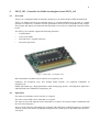
GEPHY_1X1 - Ethernet Media Access Controller for HAPS GEPHY_1x1
9.1
Overview
The Ethernet Media Access Controller for the Synplicity HAPS GEPHY_1x1 daughter boards provides an interface between an AMBA-AHB bus and an Ethernet network. The controller provides two
Ethernet cores and supports 10/100/1000 Mbit speed in both full- and half-duplex. The AMBA interface of each Ethernet core consists of an APB interface for configuration and control and an AHB
master interface which handles the dataflow. The dataflow is handled through DMA channels.
The Ethernet Media Access Controller is based on the Gaisler Research GRETH - Ethernet Media
Access Controller and GRETH_GBIT - Gigabit Ethernet Media Access Controller. See corresponding
manual for details. The GRETH IP core is provided in VHDL source code as part of the GRLIB GPL
distribution. The GRETH_GBIT IP core is only available in the GRLIB COM distribution.
Figure 8. HAPS GRPHY_1x1 daughter board
More information on HAPS can be found at www.synplicity.com.
Synplicity, the Synplicity logo, and “Simply Better Results” are registered trademarks of
Synplicity, Inc.
HAPS, the HAPS logo, “High-performance ASIC Prototyping System”, and HapsTrak, HapsTrak I
and HapsTrak II are trademarks of Synplicity, Inc.
9.2
Vendor and device identifier
The core has vendor identifier 0x01 (Gaisler Research) and device identifier 0x01D. For description
of vendor and device identifiers, see GRLIB IP Library User’s Manual.
34
9.3
Configuration options
Table 37 shows additional configuration options of the core (VHDL generics) not described in the
GRETH/GRETH_GBIT core manual.
Table 37. Configuration options
9.4
Generic
Function
Allowed range
Default
grethen0
Enables Ethernet interface 0
0-1
1
giga0
Enables the Gigabit MAC for Ethernet interface 0
0-1
0
grethen1
Enables Ethernet interface 1
0-1
1
giga1
Enables the Gigabit MAC for Ethernet interface 1
0-1
0
Library dependencies
Table 38 shows libraries used when instantiating the core (VHDL libraries).
Table 38. Library dependencies
9.5
Library
Package
Imported unit(s)
Description
GRLIB
AMBA
Signals
AMBA signal definitions
GAISLER
NET
Signals, components
Signal declarations
GAISLER
HAPS
Component
Component declaration
Component declaration
The core has the following component declaration.
component gephy_1x1 is
generic(
grethen0
: integer
hindex0
: integer
pindex0
: integer
paddr0
: integer
pmask0
: integer
pirq0
: integer
fifosize0
: integer
edcl0
: integer
edclbufsz0
: integer
burstlength0
: integer
macaddrh0
: integer
macaddrl0
: integer
ipaddrh0
: integer
ipaddrl0
: integer
phyrstadr0
: integer
giga0
: integer
grethen1
: integer
hindex1
: integer
pindex1
: integer
paddr1
: integer
pmask1
: integer
pirq1
: integer
fifosize1
: integer
edcl1
: integer
edclbufsz1
: integer
burstlength1
: integer
macaddrh1
: integer
macaddrl1
: integer
ipaddrh1
: integer
ipaddrl1
: integer
phyrstadr1
: integer
giga1
: integer
sim
: integer
:= 1;
:= 0;
:= 0;
:= 0;
:= 16#FFF#;
:= 0;
range 4 to 64 := 8;
range 0 to 1 := 0;
range 1 to 64 := 1;
range 4 to 128 := 32;
:= 16#00005E#;
:= 16#000000#;
:= 16#c0a8#;
:= 16#0035#;
range 0 to 32 := 0;
range 0 to 1 := 0;
:= 1;
:= 0;
:= 0;
:= 0;
:= 16#FFF#;
:= 0;
range 4 to 64 := 8;
range 0 to 1 := 0;
range 1 to 64 := 1;
range 4 to 128 := 32;
:= 16#00005E#;
:= 16#000000#;
:= 16#c0a8#;
:= 16#0035#;
range 0 to 32 := 0;
range 0 to 1 := 0;
range 0 to 1 := 0;
35
nsync
mdcscaler
memtech
oepol
scanen
);
port(
rst
clk
ahbmi0
ahbmo0
apbi0
apbo0
ethi0
etho0
ahbmi1
ahbmo1
apbi1
apbo1
ethi1
etho1
end component;
9.6
:
:
:
:
:
integer
integer
integer
integer
integer
:
:
:
:
:
:
:
:
:
:
:
:
:
:
in
in
in
out
in
out
in
out
in
out
in
out
in
out
range
range
:= 0;
range
range
1 to 2 := 2;
0 to 255 := 25;
0 to 1
0 to 1
:= 0;
:= 0
std_ulogic;
std_ulogic;
ahb_mst_in_type;
ahb_mst_out_type;
apb_slv_in_type;
apb_slv_out_type;
eth_in_type;
eth_out_type;
ahb_mst_in_type;
ahb_mst_out_type;
apb_slv_in_type;
apb_slv_out_type;
eth_in_type;
eth_out_type);
Instantiation
This example shows how the core can be instantiated.
library ieee;
use ieee.std_logic_1164.all;
library grlib;
use grlib.amba.all;
library gaisler;
use gaisler.haps.all;
entity greth_ex is
port (
clk : in std_ulogic;
rstn : in std_ulogic;
-- ethernet signals
ethi0 : in eth_in_type;
etho0 : in eth_out_type
ethi1 : in eth_in_type;
etho1 : in eth_out_type
);
end;
architecture rtl of greth_ex is
-- AMBA signals
signal apbi : apb_slv_in_type;
signal apbo : apb_slv_out_vector := (others => apb_none);
signal ahbmi : ahb_mst_in_type;
signal ahbmo : ahb_mst_out_vector := (others => ahbm_none);
begin
-- AMBA Components are instantiated here
...
-- GRETH
e1 : gephy_1x1
generic map(
grethen0
hindex0
pindex0
paddr0
pirq0
burstlength0
edcl0
=>
=>
=>
=>
=>
=>
=>
1,
0,
12,
12,
12,
32,
1,
36
edclbufsz0
macaddrh0
macaddrl0
ipaddrh0
ipaddrl0
giga0
grethen1
hindex1
pindex1
paddr1
pirq 1
burstlength1
edcl1
edclbufsz1
macaddrh1
macaddrl1
ipaddrh1
ipaddrl1
giga1
memtech
mdcscaler
nsync
port map(
rst
clk
ahbmi0
ahbmo0
apbi0
apbo0
ethi0
etho0
ahbmi1
ahbmo1
apbi1
apbo1
ethi1
etho1
);
end;
=>
=>
=>
=>
=>
=>
=>
=>
=>
=>
=>
=>
=>
=>
=>
=>
=>
=>
=>
=>
=>
=>
8,
16#00005E#,
16#00005D#,
16#c0a8#,
16#0035#,
0,
1,
1,
13,
13,
13,
32,
1,
8,
16#00005E#,
16#00005D#,
16#c0a8#,
16#0035#,
0,
inferred,
50,
1)
=> rstn,
=> clk,
=> ahbmi,
=> ahbmo(0),
=> apbi,
=> apbo(12),
=> ethi,
=> etho
=> ahbmi,
=> ahbmo(1),
=> apbi,
=> apbo(13),
=> ethi1,
=> etho1
37
9.7
HapsMap file for HapsTrak controller
HapsMap is a pin assignment software from Synplicity that generates Xilinx UCF files describing the
mapping from RTL port names (VHDL or Verilog) to pins for all FPGAs in a HAPS system. The program consists of a script based “engine” and a library of text files (.map) describing the different
HAPS motherboards and different HAPS daughter boards. If additional cards are created, or if custom
made daughter boards are created, these are possible to use with HapsMap, once files describing the
mapping of pins to signals on the specific boards (.map files) have been added to the library.
More information on HAPS, HapsTrak and HapsMap can be found at www.synplicity.com.
A HapsMap mapping file has been crated for the HapsTrak controller and is defined hereunder. If not
already existing in the ./cardlib directory of the HapsMap installation, the text hereunder should be
copied and pasted into a file named hapstrak.map that should be placed in the aforementioned directory, i.e. ./cardlib/hapstrak.map. The HapsMap software can then be used to map the HapsTrak controller to any HapsTrak I/II connector on any HAPS motherboard.
#
#
#
#
#
#
#
#
#
#
Connection vs signal name for HapsTrak II connector:
Nov 5 2007
Sandi Habinc <[email protected]>
Revisions:
2007-11-05 Sandi Habinc
New file
Please contact Synplicity if you have any questions.
top
bottom
signal_name
J1_A1
J1_A2
J1_A3
J1_A4
J1_A5
J1_A6
J1_A7
J1_A8
J1_A9
J1_A10
J1_A11
J1_A12
J1_A13
J1_A14
J1_A15
J1_A16
J1_A17
J1_A18
J1_A19
J1_A20
J1_A21
J1_A22
J1_A23
J1_A24
J1_A25
J1_A26
J1_A27
J1_A28
J1_A29
J1_A30
J1_A1
J1_A2
J1_A3
J1_A4
J1_A5
J1_A6
J1_A7
J1_A8
J1_A9
J1_A10
J1_A11
J1_A12
J1_A13
J1_A14
J1_A15
J1_A16
J1_A17
J1_A18
J1_A19
J1_A20
J1_A21
J1_A22
J1_A23
J1_A24
J1_A25
J1_A26
J1_A27
J1_A28
J1_A29
J1_A30
abstract(1)
abstract(2)
abstract(3)
abstract(4)
abstract(5)
abstract(6)
abstract(7)
abstract(8)
abstract(9)
abstract(10)
abstract(11)
abstract(12)
abstract(13)
abstract(14)
abstract(15)
abstract(16)
abstract(17)
abstract(18)
abstract(19)
abstract(20)
abstract(21)
abstract(22)
abstract(23)
abstract(24)
abstract(25)
abstract(26)
abstract(27)
abstract(28)
abstract(29)
abstract(30)
J1_A31
J1_A32
J1_A33
J1_A34
J1_A35
J1_A36
J1_A37
J1_A38
J1_A31
J1_A32
J1_A33
J1_A34
J1_A35
J1_A36
J1_A37
J1_A38
abstract(33)
abstract(34)
abstract(35)
abstract(36)
abstract(37)
abstract(38)
abstract(39)
abstract(40)
38
J1_A39
J1_A40
J1_A41
J1_A42
J1_A43
J1_A44
J1_A45
J1_A46
J1_A47
J1_A48
J1_A49
J1_A50
J1_A51
J1_A52
J1_A53
J1_A54
J1_A55
J1_A56
J1_A57
J1_A58
J1_A59
J1_A60
J1_A39
J1_A40
J1_A41
J1_A42
J1_A43
J1_A44
J1_A45
J1_A46
J1_A47
J1_A48
J1_A49
J1_A50
J1_A51
J1_A52
J1_A53
J1_A54
J1_A55
J1_A56
J1_A57
J1_A58
J1_A59
J1_A60
abstract(41)
abstract(42)
abstract(43)
abstract(44)
abstract(45)
abstract(46)
abstract(47)
abstract(48)
abstract(49)
abstract(50)
abstract(51)
abstract(52)
abstract(53)
abstract(54)
abstract(55)
abstract(56)
abstract(57)
abstract(58)
abstract(59)
abstract(60)
abstract(61)
abstract(62)
J1_B1
J1_B2
J1_B3
J1_B4
J1_B5
J1_B6
J1_B7
J1_B8
J1_B9
J1_B10
J1_B11
J1_B12
J1_B13
J1_B14
J1_B15
J1_B16
J1_B17
J1_B18
J1_B19
J1_B20
J1_B21
J1_B22
J1_B23
J1_B24
J1_B25
J1_B26
J1_B27
J1_B28
J1_B29
J1_B30
J1_B1
J1_B2
J1_B3
J1_B4
J1_B5
J1_B6
J1_B7
J1_B8
J1_B9
J1_B10
J1_B11
J1_B12
J1_B13
J1_B14
J1_B15
J1_B16
J1_B17
J1_B18
J1_B19
J1_B20
J1_B21
J1_B22
J1_B23
J1_B24
J1_B25
J1_B26
J1_B27
J1_B28
J1_B29
J1_B30
abstract(65)
abstract(66)
abstract(67)
abstract(68)
abstract(69)
abstract(70)
abstract(71)
abstract(72)
abstract(73)
abstract(74)
abstract(75)
abstract(76)
abstract(77)
abstract(78)
abstract(79)
abstract(80)
abstract(81)
abstract(82)
abstract(83)
abstract(84)
abstract(85)
abstract(86)
abstract(87)
abstract(88)
abstract(89)
abstract(90)
abstract(91)
abstract(92)
abstract(93)
abstract(94)
J1_B31
J1_B32
J1_B33
J1_B34
J1_B35
J1_B36
J1_B37
J1_B38
J1_B39
J1_B40
J1_B41
J1_B42
J1_B43
J1_B44
J1_B45
J1_B46
J1_B47
J1_B31
J1_B32
J1_B33
J1_B34
J1_B35
J1_B36
J1_B37
J1_B38
J1_B39
J1_B40
J1_B41
J1_B42
J1_B43
J1_B44
J1_B45
J1_B46
J1_B47
abstract(97)
abstract(98)
abstract(99)
abstract(100)
abstract(101)
abstract(102)
abstract(103)
abstract(104)
abstract(105)
abstract(106)
abstract(107)
abstract(108)
abstract(109)
abstract(110)
abstract(111)
abstract(112)
abstract(113)
39
J1_B48
J1_B49
J1_B50
J1_B51
J1_B52
J1_B53
J1_B54
J1_B55
J1_B56
J1_B57
J1_B58
J1_B59
J1_B48
J1_B49
J1_B50
J1_B51
J1_B52
J1_B53
J1_B54
J1_B55
J1_B56
J1_B57
J1_B58
J1_B59
abstract(114)
abstract(115)
abstract(116)
abstract(117)
abstract(118)
abstract(119)
abstract(120)
abstract(121)
abstract(122)
abstract(123)
abstract(124)
abstract(125)
#J1_B60
J1_B60
abstract(126)
#J1_H1
#J1_H2
#J1_H3
#J1_H4
#J1_H5
#J1_H6
#J1_H7
#J1_H8
J1_H1
J1_H2
J1_H3
J1_H4
J1_H5
J1_H6
J1_H7
J1_H8
abstract(64)
abstract(0)
abstract(95)
abstract(31)
abstract(96)
abstract(32)
abstract(127)
abstract(63)
40
10
LEON3 template design for HAPS-31 motherboard
10.1
Overview
The LEON3 template design for the HAPS-31 motherboard from Synplicity assumes the presence of
the SRAM_1x1, FLASH_1x1, SDRAM_1x1, DDR_1x1, and GEPHY_1x1 daughter boards and the
BIO1 I/O board.
For more information about HAPS, visit www.synplicity.com.
Figure 9. Synplicity’s HAPS-31 motherboard
The LEON3 architecture for the HAPS-31 motherboards includes the following modules:
•
•
•
•
•
•
•
•
•
•
•
•
LEON3 SPARC V8 Integer Unit (optional MMU and FPU)
Debug Support Unit with AMBA trace buffer
JTAG Debug Link
Timer unit with 32-bit timers
Interrupt controller for 15 interrupts in two priority levels
UART with FIFO and baud rate generator, accessed via the BIO1 board
AMBA AHB status register
Extra Synchronous SRAM controller (for SRAM_1x1 daughter board) (SRAM_1X1 core)
Extra PROM controller (for FLASH_1x1 daughter board) (FLASH_1X1 core)
Extra SDRAM controller (for SDRAM_1x1 daughter board) (SDRAM_1X1 core)
Extra DDR controller (for DDR_1x1 daughter board) (DDR_1X1 core)
Extra Ethernet controller (for GEPHY_1x1 daughter board) (GEPHY_1X1 core)
For more information about the GRLIB IP Library, visit www.gaisler.com.
41
3-Port Register File
IEEE-754
Mul/Div
I-Cache
ITLB
Debug
Support
Unit
D-Cache
SRMMU
JTAG
Debug
Interface
AMBA
Trace
Buffer
DTLB
FLASH_1x1
Controller
SRAM_1x1
Controller
DDR_1x1
Controller
SDRAM_1x1
Controller
HapsTrak
Controller
GEPHY_1x1
Controller
32-bit AMBA AHB
AHBCTRL
APBCTRL
LEON3MP
Instruction
Trace
Buffer
LEON3-FT SPARC
32-bit Integer Unit
CLKGEN
32-bit AMBA APB
RSTGEN
AHB STAT
IRQ
TIMERS
UART
BIO1
Figure 10. LEON3 template design for HAPS-31 motherboard
10.2
Configuration
The HAPS-31 LEON3 template design can be configured by means of commands described in the
GRLIB IP Library User’s Manual.
The Xilinx .ucf pin placement file for the motherboard can be generated from the leon3mp.pas and
leon3mp.con files using the HapsMap software from Synplicity. After editing the leon3mp.pas or
leon3mp.con file, run the following command to generate a new .ucf file:
> make hapsmap
Ensure that the hapsmap executable is the search path. For details, please refer to the HAPS manuals
from Synplicity.
The 40 MHz template design assumes an external clock frequency of 100 MHz. See HAPS-31 motherboard documentation for appropriate settings of the external clock generator circuitry. The on-board
16 MHz oscillator should be used with the settings N=1 and M=25.
Please refer to the leon3mp.con and leon3mp.pas files in the template design directory for the detail
configuration of the board.
42
10.3
Cores
The LEON3 HAPS-31 template design is based on cores from the GRLIB IP library. The vendor and
device identifiers for each core can be extracted from the plug & play information, as described in the
GRLIB IP Core User’s Manual. The used IP cores are listed in table 39.
Table 39. Used IP cores
Core
10.4
Function
Vendor
Device
AHBCTRL
AHB Arbiter & Decoder
0x01
-
APBCTRL
AHB/APB Bridge
0x01
0x006
LEON3
LEON3 SPARC V8 32-bit processor
0x01
0x003
DSU3
LEON3 Debug support unit
0x01
0x004
AHBJTAG
JTAG/AHB debug interface
0x01
0x01C
SRAM_1X1
32-bit SSRAM / PROM Controller for HAPS SRAM_1x1
0x01
0x00A
FLASH_1X1
32/16-bit PROM Controller for HAPS FLASH_1x1
0x01
0x00A
AHBSTAT
AHB failing address register
0x01
0x052
APBUART
8-bit UART with FIFO
0x01
0x00C
GPTIMER
Modular timer unit with watchdog
0x01
0x011
IRQMP
LEON3 Interrupt controller
0x01
0x00D
HAPSTRAK
HapsTrak controller for HAPS boards
0x01
0x077
SDRAM_1X1
Dual 32-bit SDRAM Controller for HAPS SDRAM_1x1
0x01
0x009
DDR_1X1
64-bit DDR266 Controller for HAPS DDR_1x1
0x01
0x025
GEPHY_1X1
Dual Ethernet Controller for HAPS GEPHY_1x1
0x01
0x01D
BIO1
BIO1 Controller for HAPS BIO1
0x01
0x07A
Interrupts
All interrupts are handled by the interrupt controller and forwarded to the LEON3 processor. See the
GRLIB IP Core User’s Manual for how and when the interrupts are raised.
Table 40. Interrupt assignment
Core
Interrupt
AHBSTAT
7
APBUART
2
GPTIMER
8, 9
GEPHY_1X1
10, 12
Comment
43
10.5
Memory map
The memory map shown in table 41 is based on the AMBA AHB address space. Access to addresses
outside the ranges will return an AHB error response.
Table 41. AMBA AHB address range
Core
Address range
Area
FLASH_1X1
0x00000000 - 0x10000000
Flash PROM area (not all used)
SRAM_1X1
0x40000000 - 0x80000000
SSRAM area (not all used)
APBCTRL
0x80000000 - 0x81000000
APB bridge
DSU3
0x90000000 - 0xA0000000
Registers
DDR_1X1
0xA0000000 - 0xB0000000
DDR area
SDRAM_1X1
0xB0000000 - 0xC0000000
SDRAM area
SDRAM_1X1
0xC0000000 - 0xD0000000
DDR_1X1
0xFFF00200 - 0xFFF00300
Registers for DDR_1X1 controller
SDRAM_1X1
0xFFF00300 - 0xFFF00400
Registers for SDRAM_1X1 controller
SDRAM_1X1
0xFFF00400 - 0xFFF00500
AHB plug&play
0xFFFFF000 - 0xFFFFFFFF
Registers
The control registers of most on-chip peripherals are accessible via the AHB/APB bridge, which is
mapped at address 0x80000000. The memory map shown in table 42 is based on the AMBA AHB
address space.The detailed register layout is defined in the GRLIB IP Core User’s Manual.
Table 42. APB address range
10.6
Core
Address range
Comment
SRAM_1X1
0x80000000 - 0x80000100
Used with extra SRAM_1x1 daughter board
APBUART
0x80000100 - 0x80000200
IRQMP
0x80000200 - 0x80000300
GPTIMER
0x80000300 - 0x80000400
FLASH_1X1
0x80000400 - 0x80000500
Used with extra FLASH_1x1 daughter board
BIO1
0x80000500 - 0x80000600
Used with extra BIO1 I/O board
HAPSTRAK
0x80000900 - 0x80000A00
GEPHY_1X1
0x80000A00 - 0x80000B00
GEPHY_1X1
0x80000B00 - 0x80000C00
AHBSTAT
0x80000F00 - 0x80001000
APB plug&play
0x800FF000 - 0x80100000
Used with extra GEPHY_1x1 daughter board
Setup
This describes the setup for the HAPS-31 motherboard:
•
•
•
•
•
•
Configure voltage region V1, V2, and V3 to 3.3V
Configure voltage region V4 and V5 to 2.5V
Configure the frequency select switch to 01011_00101 (100 MHz)
Connect the SRAM_1x1 on connector A1
Voltage select: int (2-3), PLL on: S1
Connect the BIO1 to GPIO[1:10]
Connect the FLASH_1x1 on connector A3 (Optional)
Jumper J2 and J4: Word mode (1-2)
44
•
•
•
•
•
•
•
Connect the SDRAM_1x1 on connector A2 (Optional)
Connect the DDR_1x1 on connector A5 (Optional)
Connect the GEPHY_1x1 on connector A4 (Optional)
Jumper J4: int voltage source, Jumper J5 and J7: 2.5V
Jumper J6 and J8: 125 MHz
Connect the Xilinx USB cable to JTAG IN
iMPACT: Configure the board with the design
"c:\haps\gaisler\designs\leon3-hardi-haps31\bitfiles\leon3mp.bit"
iMPACT: Select Output -> Cable Disconnect (important)
Use GRMON to connect to the LEON3 processor.
45
11
LEON3 template design for HAPS-51 motherboard
11.1
Overview
The LEON3 template design for the HAPS-51 motherboard from Synplicity assumes the presence of
the SDRAM_1x1, DDR_1x1, and GEPHY_1x1 daughter boards and the BIO1 I/O board (although
not strictly necessary).
For more information about HAPS, visit www.synplicity.com.
Figure 11. Synplicity’s HAPS-51 motherboard
The LEON3 architecture for the HAPS-51 motherboards includes the following modules:
•
•
•
•
•
•
•
•
•
•
•
•
•
•
•
LEON3 SPARC V8 Integer Unit (optional FPU and MMU)
Debug Support Unit with AMBA trace buffer
JTAG Debug Link
16-, 32- and 64-bit DDR2 Controller
Synchronous SRAM / PROM controller (SRAM_1X1 core)
Timer unit with 32-bit timers
Interrupt controller for 15 interrupts in two priority levels
UART with FIFO and baud rate generator, accessed via the BIO1 board
AMBA AHB status register
Extra HapsTrak controller for HAPS boards (HAPSTRAK core)
Extra SDRAM controller (for SDRAM_1x1 daughter board) (SDRAM_1X1 core)
Extra DDR controller (for DDR_1x1 daughter board) (DDR_1X1 core)
Extra Ethernet controller (for GEPHY_1x1 daughter board) (GEPHY_1X1 core)
One extra UARTs with FIFO and baud rate generator
Two extra 32-bit general purpose I/O port (GPIO)
For more information about the GRLIB IP Library, visit www.gaisler.com.
46
3-Port Register File
IEEE-754
Mul/Div
LEON3-FT SPARC
32-bit Integer Unit
I-Cache
ITLB
JTAG
Debug
Interface
Debug
Support
Unit
D-Cache
SRMMU
AMBA
Trace
Buffer
DTLB
DDR2
Controller
SRAM_1x1
Controller
DDR_1x1
Controller
SDRAM_1x1
Controller
HapsTrak
Controller
GEPHY_1x1
Controller
32-bit AMBA AHB
AHBCTRL
APBCTRL
LEON3MP
Instruction
Trace
Buffer
CLKGEN
32-bit AMBA APB
RSTGEN
AHB STAT
BIO1
IRQ
TIMERS
UART
GPIO
Figure 12. LEON3 template design for HAPS-51 motherboard
11.2
Configuration
The HAPS-51 LEON3 template design can be configured by means of commands described in the
GRLIB IP Library User’s Manual.
The Xilinx .ucf pin placement file for the motherboard can be generated from the leon3mp.pas and
leon3mp.con files using the HapsMap software from Synplicity. After editing the leon3mp.pas or
leon3mp.con file, run the following command to generate a new .ucf file:
> make hapsmap
Ensure that the hapsmap executable is the search path. For details, please refer to the HAPS manuals
from Synplicity.
The 70 MHz template design assumes an external clock frequency of 100 MHz. See HAPS-51 motherboard documentation for appropriate settings of the external clock generator circuitry. The on-board
16 MHz oscillator should be used with the settings N=1 and M=25.
Please refer to the leon3mp.con and leon3mp.pas files in the template design directory for the detail
configuration of the board.
47
11.3
Cores
The LEON3 HAPS-51 template design is based on cores from the GRLIB IP library. The vendor and
device identifiers for each core can be extracted from the plug & play information, as described in the
GRLIB IP Core User’s Manual. The used IP cores are listed in table 43.
Table 43. Used IP cores
Core
11.4
Function
Vendor
Device
AHBCTRL
AHB Arbiter & Decoder
0x01
-
APBCTRL
AHB/APB Bridge
0x01
0x006
LEON3
LEON3 SPARC V8 32-bit processor
0x01
0x003
DSU3
LEON3 Debug support unit
0x01
0x004
AHBJTAG
JTAG/AHB debug interface
0x01
0x01C
SRAM_1X1
32-bit SSRAM / PROM Controller for HAPS SRAM_1x1
0x01
0x00A
DDR2SPA
16-, 32- and 64-bit DDR2 Controller
0x01
0x02E
AHBSTAT
AHB failing address register
0x01
0x052
APBUART
8-bit UART with FIFO
0x01
0x00C
GPTIMER
Modular timer unit with watchdog
0x01
0x011
GRGPIO
General purpose I/O port
0x01
0x01A
IRQMP
LEON3 Interrupt controller
0x01
0x00D
I2CMST
I
0x01
0x028
HAPSTRAK
HapsTrak controller for HAPS boards
0x01
0x077
SDRAM_1X1
Dual 32-bit SDRAM Controller for HAPS SDRAM_1x1
0x01
0x009
2C-master
DDR_1X1
64-bit DDR266 Controller for HAPS DDR_1x1
0x01
0x025
GEPHY_1X1
Dual Ethernet Controller for HAPS GEPHY_1x1
0x01
0x01D
BIO1
BIO1 Controller for HAPS BIO1
0x01
0x07A
Interrupts
All interrupts are handled by the interrupt controller and forwarded to the LEON3 processor. See the
GRLIB IP Core User’s Manual for how and when the interrupts are raised.
Table 44. Interrupt assignment
Core
Interrupt
AHBSTAT
7
APBUART 0
2
APBUART 1
3
GPTIMER
8, 9
GEPHY_1X1
10, 12
I2CMST
11
Comment
48
11.5
Memory map
The memory map shown in table 45 is based on the AMBA AHB address space. Access to addresses
outside the ranges will return an AHB error response.
Table 45. AMBA AHB address range
Core
Address range
Area
SRAM_1X1
0x00000000 - 0x10000000
Flash PROM area (not all used)
0x40000000 - 0x60000000
SSRAM area (not all used)
0x60000000 - 0x80000000
DDR2 area (not all used)
APBCTRL
0x80000000 - 0x81000000
APB bridge
DSU3
0x90000000 - 0xA0000000
Registers
DDR_1X1
0xA0000000 - 0xB0000000
DDR area
SDRAM_1X1
0xB0000000 - 0xC0000000
SDRAM area
SDRAM_1X1
0xC0000000 - 0xD0000000
DDR2SPA
0xFFF00100 - 0xFFF00200
Registers for DDR2 controller
DDR_1X1
0xFFF00200 - 0xFFF00300
Registers for DDR_1X1 controller
SDRAM_1X1
0xFFF00300 - 0xFFF00400
Registers for SDRAM_1X1 controller
SDRAM_1X1
0xFFF00400 - 0xFFF00500
AHB plug&play
0xFFFFF000 - 0xFFFFFFFF
DDR2SPA
Registers
The control registers of most on-chip peripherals are accessible via the AHB/APB bridge, which is
mapped at address 0x80000000. The memory map shown in table 46 is based on the AMBA AHB
address space.The detailed register layout is defined in the GRLIB IP Core User’s Manual.
Table 46. APB address range
Core
Address range
SRAM_1X1
0x80000000 - 0x80000100
Comment
APBUART 0
0x80000100 - 0x80000200
IRQMP
0x80000200 - 0x80000300
Extra UART (not on HAPS-51 motherboard)
GPTIMER
0x80000300 - 0x80000400
BIO1
0x80000500 - 0x80000600
APBUART 1
0x80000600 - 0x80000700
Extra UART (not on HAPS-51 motherboard)
GRGPIO 0
0x80000700 - 0x80000800
Extra 32-bit GPIO, (not on HAPS-51 motherboard)
GRGPIO 1
0x80000800 - 0x80000900
Extra 32-bit GPIO, (not on HAPS-51 motherboard)
HAPSTRAK
0x80000900 - 0x80000A00
GEPHY_1X1
0x80000A00 - 0x80000B00
GEPHY_1X1
0x80000B00 - 0x80000C00
I2CMST
0x80000C00 - 0x80000D00
AHBSTAT
0x80000F00 - 0x80001000
APB plug&play
0x800FF000 - 0x80100000
Used with extra BIO1 I/O board
Used with extra GEPHY_1x1 daughter board
Connected to DDR2 memory
Registers
49
12
LEON3 template design for HAPS-52 motherboard
12.1
Overview
The LEON3 template design for the HAPS-52 motherboard from Synplicity assumes the presence of
the SRAM_1x1, FLASH_1x1, SDRAM_1x1, DDR_1x1 and GEPHY_1x1 daughter boards and the
BIO1 I/O board. Note that only one FPGA is used (FPGA A).
For more information about HAPS, visit www.synplicity.com.
Figure 13. Synplicity’s HAPS-52 motherboard
The LEON3 architecture for the HAPS-52 motherboards includes the following modules:
•
•
•
•
•
•
•
•
•
•
•
•
•
LEON3 SPARC V8 Integer Unit (optional MMU and FPU)
Debug Support Unit with AMBA trace buffer
JTAG Debug Link
Timer unit with 32-bit timers
Interrupt controller for 15 interrupts in two priority levels
UART with FIFO and baud rate generator, accessed via the BIO1 board
AMBA AHB status register
Extra HapsTrak controller for HAPS boards (HAPSTRAK core)
Extra Synchronous SRAM controller (for SRAM_1x1 daughter board) (SRAM_1X1 core)
Extra PROM controller (for FLASH_1x1 daughter board) (FLASH_1X1 core)
Extra SDRAM controller (for SDRAM_1x1 daughter board) (SDRAM_1X1 core)
Extra DDR controller (for DDR_1x1 daughter board) (DDR_1X1 core)
Extra Ethernet controller (for GEPHY_1x1 daughter board) (GEPHY_1X1 core)
For more information about the GRLIB IP Library, visit www.gaisler.com.
50
3-Port Register File
IEEE-754
Mul/Div
Instruction
Trace
Buffer
LEON3-FT SPARC
32-bit Integer Unit
I-Cache
ITLB
D-Cache
SRMMU
JTAG
Debug
Interface
AMBA
Trace
Buffer
DTLB
FLASH_1x1
Controller
SRAM_1x1
Controller
DDR_1x1
Controller
SDRAM_1x1
Controller
HapsTrak
Controller
GEPHY_1x1
Controller
32-bit AMBA AHB
AHBCTRL
APBCTRL
LEON3MP
Debug
Support
Unit
CLKGEN
32-bit AMBA APB
RSTGEN
AHB STAT
IRQ
TIMERS
UART
BIO1
Figure 14. LEON3 template design for HAPS-52 motherboard
12.2
Configuration
The HAPS-52 LEON3 template design can be configured by means of commands described in the
GRLIB IP Library User’s Manual.
The Xilinx .ucf pin placement file for the motherboard can be generated from the leon3mp.pas and
leon3mp.con files using the HapsMap software from Synplicity. After editing the leon3mp.pas or
leon3mp.con file, run the following command to generate a new .ucf file:
> make hapsmap
Ensure that the hapsmap executable is the search path. For details, please refer to the HAPS manuals
from Synplicity.
The 70 MHz template design assumes an external clock frequency of 100 MHz. See HAPS-52 motherboard documentation for appropriate settings of the external clock generator circuitry. The on-board
16 MHz oscillator should be used with the settings N=1 and M=25.
Please refer to the leon3mp.con and leon3mp.pas files in the template design directory for the detail
configuration of the board.
51
12.3
Cores
The LEON3 HAPS-52 template design is based on cores from the GRLIB IP library. The vendor and
device identifiers for each core can be extracted from the plug & play information, as described in the
GRLIB IP Core User’s Manual. The used IP cores are listed in table 47.
Table 47. Used IP cores
Core
12.4
Function
Vendor
Device
AHBCTRL
AHB Arbiter & Decoder
0x01
-
APBCTRL
AHB/APB Bridge
0x01
0x006
LEON3
LEON3 SPARC V8 32-bit processor
0x01
0x003
DSU3
LEON3 Debug support unit
0x01
0x004
AHBJTAG
JTAG/AHB debug interface
0x01
0x01C
SRAM_1X1
32-bit SSRAM / PROM Controller for HAPS SRAM_1x1
0x01
0x00A
FLASH_1X1
32/16-bit PROM Controller for HAPS FLASH_1x1
0x01
0x00A
AHBSTAT
AHB failing address register
0x01
0x052
APBUART
8-bit UART with FIFO
0x01
0x00C
GPTIMER
Modular timer unit with watchdog
0x01
0x011
IRQMP
LEON3 Interrupt controller
0x01
0x00D
HAPSTRAK
HapsTrak controller for HAPS boards
0x01
0x077
SDRAM_1X1
Dual 32-bit SDRAM Controller for HAPS SDRAM_1x1
0x01
0x009
DDR_1X1
64-bit DDR266 Controller for HAPS DDR_1x1
0x01
0x025
GEPHY_1X1
Dual Ethernet Controller for HAPS GEPHY_1x1
0x01
0x01D
BIO1
BIO1 Controller for HAPS BIO1
0x01
0x07A
Interrupts
All interrupts are handled by the interrupt controller and forwarded to the LEON3 processor. See the
GRLIB IP Core User’s Manual for how and when the interrupts are raised.
Table 48. Interrupt assignment
Core
Interrupt
AHBSTAT
7
APBUART
2
GPTIMER
8, 9
GEPHY_1X1
10, 12
Comment
52
12.5
Memory map
The memory map shown in table 49 is based on the AMBA AHB address space. Access to addresses
outside the ranges will return an AHB error response.
Table 49. AMBA AHB address range
Core
Address range
Area
FLASH_1X1
0x00000000 - 0x10000000
Flash PROM area (not all used)
SRAM_1X1
0x40000000 - 0x80000000
SSRAM area (not all used)
APBCTRL
0x80000000 - 0x81000000
APB bridge
DSU3
0x90000000 - 0xA0000000
Registers
DDR_1X1
0xA0000000 - 0xB0000000
DDR area
SDRAM_1X1
0xB0000000 - 0xC0000000
SDRAM area
SDRAM_1X1
0xC0000000 - 0xD0000000
DDR_1X1
0xFFF00200 - 0xFFF00300
Registers for DDR_1X1 controller
SDRAM_1X1
0xFFF00300 - 0xFFF00400
Registers for SDRAM_1X1 controller
SDRAM_1X1
0xFFF00400 - 0xFFF00500
AHB plug&play
0xFFFFF000 - 0xFFFFFFFF
Registers
The control registers of most on-chip peripherals are accessible via the AHB/APB bridge, which is
mapped at address 0x80000000. The memory map shown in table 50 is based on the AMBA AHB
address space.The detailed register layout is defined in the GRLIB IP Core User’s Manual.
Table 50. APB address range
Core
Address range
Comment
SRAM_1X1
0x80000000 - 0x80000100
Used with extra SRAM_1x1 daughter board
APBUART
0x80000100 - 0x80000200
IRQMP
0x80000200 - 0x80000300
GPTIMER
0x80000300 - 0x80000400
FLASH_1X1
0x80000400 - 0x80000500
Used with extra FLASH_1x1 daughter board
BIO1
0x80000500 - 0x80000600
Used with extra BIO1 I/O board
HAPSTRAK
0x80000900 - 0x80000A00
GEPHY_1X1
0x80000A00 - 0x80000B00
GEPHY_1X1
0x80000B00 - 0x80000C00
AHBSTAT
0x80000F00 - 0x80001000
APB plug&play
0x800FF000 - 0x80100000
Used with extra GEPHY_1x1 daughter board
53
13
LEON3 template design for HAPS-54 motherboard
13.1
Overview
The LEON3 template design for the HAPS-54 motherboard from Synplicity assumes the presence of
the SRAM_1x1, FLASH_1x1, SDRAM_1x1, DDR_1x1 and GEPHY_1x1 daughter boards and the
BIO1 I/O board. Note that only one FPGA is used (FPGA A).
For more information about HAPS, visit www.synplicity.com.
Figure 15. Synplicity’s HAPS-54 motherboard
The LEON3 architecture for the HAPS-54 motherboards includes the following modules:
•
•
•
•
•
•
•
•
•
•
•
•
•
LEON3 SPARC V8 Integer Unit (optional MMU and FPU)
Debug Support Unit with AMBA trace buffer
JTAG Debug Link
Timer unit with 32-bit timers
Interrupt controller for 15 interrupts in two priority levels
UART with FIFO and baud rate generator, accessed via the BIO1 board
AMBA AHB status register
Extra HapsTrak controller for HAPS boards (HAPSTRAK core)
Extra Synchronous SRAM controller (for SRAM_1x1 daughter board) (SRAM_1X1 core)
Extra PROM controller (for FLASH_1x1 daughter board) (FLASH_1X1 core)
Extra SDRAM controller (for SDRAM_1x1 daughter board) (SDRAM_1X1 core)
Extra DDR controller (for DDR_1x1 daughter board) (DDR_1X1 core)
Extra Ethernet controller (for GEPHY_1x1 daughter board) (GEPHY_1X1 core)
For more information about the GRLIB IP Library, visit www.gaisler.com.
54
3-Port Register File
IEEE-754
Mul/Div
Instruction
Trace
Buffer
LEON3-FT SPARC
32-bit Integer Unit
I-Cache
ITLB
D-Cache
SRMMU
JTAG
Debug
Interface
AMBA
Trace
Buffer
DTLB
FLASH_1x1
Controller
SRAM_1x1
Controller
DDR_1x1
Controller
SDRAM_1x1
Controller
HapsTrak
Controller
GEPHY_1x1
Controller
32-bit AMBA AHB
AHBCTRL
APBCTRL
LEON3MP
Debug
Support
Unit
CLKGEN
32-bit AMBA APB
RSTGEN
AHB STAT
IRQ
TIMERS
UART
BIO1
Figure 16. LEON3 template design for HAPS-54 motherboard
13.2
Configuration
The HAPS-54 LEON3 template design can be configured by means of commands described in the
GRLIB IP Library User’s Manual.
The Xilinx .ucf pin placement file for the motherboard can be generated from the leon3mp.pas and
leon3mp.con files using the HapsMap software from Synplicity. After editing the leon3mp.pas or
leon3mp.con file, run the following command to generate a new .ucf file:
> make hapsmap
Ensure that the hapsmap executable is the search path. For details, please refer to the HAPS manuals
from Synplicity.
The 70 MHz template design assumes an external clock frequency of 100 MHz. See HAPS-54 motherboard documentation for appropriate settings of the external clock generator circuitry. The on-board
16 MHz oscillator should be used with the settings N=1 and M=25.
Please refer to the leon3mp.con and leon3mp.pas files in the template design directory for the detail
configuration of the board.
55
13.3
Cores
The LEON3 HAPS-54 template design is based on cores from the GRLIB IP library. The vendor and
device identifiers for each core can be extracted from the plug & play information, as described in the
GRLIB IP Core User’s Manual. The used IP cores are listed in table 51.
Table 51. Used IP cores
Core
13.4
Function
Vendor
Device
AHBCTRL
AHB Arbiter & Decoder
0x01
-
APBCTRL
AHB/APB Bridge
0x01
0x006
LEON3
LEON3 SPARC V8 32-bit processor
0x01
0x003
DSU3
LEON3 Debug support unit
0x01
0x004
AHBJTAG
JTAG/AHB debug interface
0x01
0x01C
SRAM_1X1
32-bit SSRAM / PROM Controller for HAPS SRAM_1x1
0x01
0x00A
FLASH_1X1
32/16-bit PROM Controller for HAPS FLASH_1x1
0x01
0x00A
AHBSTAT
AHB failing address register
0x01
0x052
APBUART
8-bit UART with FIFO
0x01
0x00C
GPTIMER
Modular timer unit with watchdog
0x01
0x011
IRQMP
LEON3 Interrupt controller
0x01
0x00D
HAPSTRAK
HapsTrak controller for HAPS boards
0x01
0x077
SDRAM_1X1
Dual 32-bit SDRAM Controller for HAPS SDRAM_1x1
0x01
0x009
DDR_1X1
64-bit DDR266 Controller for HAPS DDR_1x1
0x01
0x025
GEPHY_1X1
Dual Ethernet Controller for HAPS GEPHY_1x1
0x01
0x01D
BIO1
BIO1 Controller for HAPS BIO1
0x01
0x07A
Interrupts
All interrupts are handled by the interrupt controller and forwarded to the LEON3 processor. See the
GRLIB IP Core User’s Manual for how and when the interrupts are raised.
Table 52. Interrupt assignment
Core
Interrupt
AHBSTAT
7
APBUART
2
GPTIMER
8, 9
GEPHY_1X1
10, 12
Comment
56
13.5
Memory map
The memory map shown in table 53 is based on the AMBA AHB address space. Access to addresses
outside the ranges will return an AHB error response.
Table 53. AMBA AHB address range
Core
Address range
Area
FLASH_1X1
0x00000000 - 0x10000000
Flash PROM area (not all used)
SRAM_1X1
0x40000000 - 0x80000000
SSRAM area (not all used)
APBCTRL
0x80000000 - 0x81000000
APB bridge
DSU3
0x90000000 - 0xA0000000
Registers
DDR_1X1
0xA0000000 - 0xB0000000
DDR area
SDRAM_1X1
0xB0000000 - 0xC0000000
SDRAM area
SDRAM_1X1
0xC0000000 - 0xD0000000
DDR_1X1
0xFFF00200 - 0xFFF00300
Registers for DDR_1X1 controller
SDRAM_1X1
0xFFF00300 - 0xFFF00400
Registers for SDRAM_1X1 controller
SDRAM_1X1
0xFFF00400 - 0xFFF00500
AHB plug&play
0xFFFFF000 - 0xFFFFFFFF
Registers
The control registers of most on-chip peripherals are accessible via the AHB/APB bridge, which is
mapped at address 0x80000000. The memory map shown in table 54 is based on the AMBA AHB
address space.The detailed register layout is defined in the GRLIB IP Core User’s Manual.
Table 54. APB address range
Core
Address range
Comment
SRAM_1X1
0x80000000 - 0x80000100
Used with extra SRAM_1x1 daughter board
APBUART
0x80000100 - 0x80000200
IRQMP
0x80000200 - 0x80000300
GPTIMER
0x80000300 - 0x80000400
FLASH_1X1
0x80000400 - 0x80000500
Used with extra FLASH_1x1 daughter board
BIO1
0x80000500 - 0x80000600
Used with extra BIO1 I/O board
HAPSTRAK
0x80000900 - 0x80000A00
GEPHY_1X1
0x80000A00 - 0x80000B00
GEPHY_1X1
0x80000B00 - 0x80000C00
AHBSTAT
0x80000F00 - 0x80001000
APB plug&play
0x800FF000 - 0x80100000
Used with extra GEPHY_1x1 daughter board
57
14
Application note for HAPS-50 motherboard demonstration
14.1
Overview
This is an instructions for how to run a simple demo on the HAPS-51, HAPS-52 and HAPS-54
boards. The design running on the HAPS motherboards includes a LEON3 SPARC V8 processor.
In reference to the board descriptions in the previous sections, the LEON3 processor is connected to a
32-bit AMBA AHB bus. Among other things, this AHB bus is connected to a SSRAM controller,
which handles the on-board SSRAM and Flash PROM on the HAPS-51 motherboard, and
SRAM_1x1 and FLASH_1x1 daughter boards on the HAPS-52 and HAPS-54 motherboards. Via an
AHB to APB bus bridge, the LEON3 processor can access controllers implemented to interface to the
BIO1 board and to a general HapsTrak connector.
In the running of a simple demo application, the LEON3 processor software is placed in the SSRAM,
and the code executes accesses to/from the BIO1 board in order to read buttons and control the LEDs.
Figure 17. Synplicity’s HAPS-51 motherboard and PC used for demonstration
This application note is based on the GRLIB IP Core Library and the GRMON debug monitor software from Gaisler Research. Although these instructions are written for Windows based PC/Laptop
usage, full Linux support is also provided for the library and the debug monitor software.
14.2
Hardware requirements
The following hardware is required:
•
PC/Laptop running Windows 2000/XP (not Vista)
•
Xilinx Platform USB Cable, version 9G or later
•
HAPS-51 with a BIO1 board (with optional GEPHY_1x1, SDRAM_1x1, DDR_1x1), or
•
HAPS-52 with a BIO1 board and an SRAM_1x1 board (with optional FLASH_1x1,
GEPHY_1x1, SDRAM_1x1, DDR_1x1), or
•
HAPS-54 with a BIO1 board and an SRAM_1x1 board (with optional FLASH_1x1,
GEPHY_1x1, SDRAM_1x1, DDR_1x1)
58
14.3
Software requirements
The following software is required:
14.4
•
HAPS GPL distribution including bitfiles for template designs from http://www.gaisler.com
•
GRMON (debug monitor software) from http://www.gaisler.com
Used to control the LEON3 processor, and more specifically load new programs.
•
SPARC-ELF-GCC (if compilation is desired), from http://www.gaisler.com
•
LibUsb-Win32 from http://libusb-win32.sourceforge.net
A filter driver needed by GRMON to access the Xilinx USB cable.
•
Xilinx ISE 9.2.03i or later, or corresponding web pack version
Downloads
HAPS GPL, GRMON and SPARC-ELF-GCC can be downloaded from http://www.gaisler.com
•
Downloads -> LEON/GRLIB -> grlib-haps-1.0.18.tar.gz (or later)
•
Downloads -> GRMON -> grmon-eval-1.1.28.tar.gz (or later)
•
Downloads -> Compilers -> BCC binaries for Linux and Windows -> windows ->
sparc-elf-3.4.4-1.0.30-mingw.zip (or later)
Note that only the HAPS GPL distribution with programming files for the LEON3 template designs is
required for the demonstration of the LEON3 processor on the HAPS-50 motherboards. For those
wanting to modify the HAPS template designs, the complete GRLIB IP core library also needs to be
downloaded in source from http://www.gaisler.com. After the GRLIB IP core library has been downloaded and extracted, the grlib-haps-*.*.*.tar.gz should be extracted into the grlib directory.
•
14.5
Downloads -> LEON/GRLIB -> grlib-gpl-1.0.18-*.tar.gz (or later)
Software installation
For explanation purposes, the installation instruction assumes the installation directory is
c:\haps\gaisler\, and that the design files are located in c:\haps\gaisler\designs\.
HAPS GPL bitfiles:
•
Unzip the file grlib-haps-1.0.18.tar.gz (or later) in the installation directory, thereby creating the
c:\haps\gaisler\designs\ directory,
(and also the c:\haps\gaisler\lib\gaisler\haps and c:\haps\gaisler\boards directories not used here).
LibUsb-Win32:
•
Run libusb-win32-filter-bin-0.1.12.1.exe (or later) and follow the instructions.
GRMON:
•
Unzip the file grmon-eval-1.1.28.tar.gz (or later) and place the folder “win32”
(with five files in it) in the installation directory.
•
Add the search path to the file “grmon-eval.exe”, i.e.
“c:\haps\gaisler\win32\”, to the environment variable PATH.
SPARC-ELF-GCC: (if compilation is desired)
•
Unzip the file sparc-elf-3.4.4-1.0.30-mingw.zip (or later) and place the folder “sparc-elf-3.4.4” in
the installation directory.
•
Add the search path to the directory “bin”, i.e. “c:\haps\gaisler\sparc-elf-3.4.4\bin”, to the environment variable PATH.
59
14.6
Hardware setup
14.6.1 Setting up the HAPS-51 motherboard
This describes the setup for the HAPS-51 motherboard:
•
Configure voltage region V1b, V2a, and V3b to 3.3V
•
Configure voltage region V2b and V3a to 2.5V
•
Connect the BIO1 to GPIO[1:10]
•
Connect the GEPHY_1x1 on connector A5 (Optional)
Jumper J4: int voltage source, Jumper J5 and J7: 2.5V
Jumper J6 and J8: 125 MHz
•
Connect the SDRAM_1x1 on connector A2 (Optional)
•
Connect the DDR_1x1 on connector A4 (Optional)
•
Configure the frequency select switch 1 to 00011_00101 (100 MHz)
•
Connect a coax cable from OSC1_a to GC1
•
Connect the Xilinx USB cable to JTAG IN
•
iMPACT: Configure the board with the design
“c:\haps\gaisler\designs\leon3-hardi-haps51\bitfiles\leon3mp.bit”
•
iMPACT: Select Output -> Cable Disconnect (important)
•
Use GRMON to connect to the LEON3 processor.
14.6.2 Setting up the HAPS-52 motherboard
This describes the setup for the HAPS-52 motherboard:
•
Configure voltage region V1a, V1b, V3a, and V3b to 3.3V
•
Configure voltage region V2b and V2a to 2.5V
•
Configure the SETUP switch to 00000_00000 (default)
•
Configure the frequency select switch 1 to 00011_00101 (100 MHz)
•
Connect a MMCX coax cable between OSC 1a and GCLK_IN 1
•
Connect the BIO1 to GPIO[1:10]
•
Connect the SRAM_1x1 on connector A3
Voltage select: int (2-3), PLL on: S1
Connect the FLASH_1x1 on connector A1 (Optional)
Jumper J2 and J4: Word mode (1-2)
•
•
•
Connect the GEPHY_1x1 on connector A5 (Optional)
Jumper J4: int voltage source, Jumper J5 and J7: 2.5V
Jumper J6 and J8: 125 MHz
Connect the SDRAM_1x1 on connector A2 (Optional)
•
Connect the DDR_1x1 on connector A6 (Optional)
•
Connect the Xilinx USB cable to JTAG IN
•
iMPACT: Configure the board with the design
"c:\haps\gaisler\designs\leon3-hardi-haps52\bitfiles\leon3mp.bit"
•
iMPACT: Select Output -> Cable Disconnect (important)
•
Use GRMON to connect to the LEON3 processor.
60
If FPGA A is the only configured device on the HAPS-52 board, the reset mask for FPGA A needs to
be modified. Otherwise, the design will be held in reset until FPGA B is configured as well. If this is
the case, do like this:
•
Connect to the RS232 port on the HAPS-52 board using a terminal emulator (HyperTerminal) set
to 38400 8-N-1.
•
Press enter to activate the HAPS-52 prompt.
•
Use the following command to set the FPGA A reset mask register:
HAPS-52> wsr 31 08
•
iMPACT: Configure the board with the design
"c:\haps\gaisler\designs\leon3-hardi-haps52\bitfiles\leon3mp.bit"
•
iMPACT: Select Output -> Cable Disconnect (important)
•
Use GRMON to connect to the running LEON3 processor.
14.6.3 Setting up the HAPS-54 motherboard
This describes the setup for the HAPS-54 motherboard:
•
Configure voltage region V1a, V1b, V3a, and V3b to 3.3V
•
Configure voltage region V2b and V2a to 2.5V
•
Configure the SETUP switch to 00000_00000 (default)
•
Configure the frequency select switch 1 to 00011_00101 (100 MHz)
•
Connect a MMCX coax cable between OSC 1a and GCLK_IN 1
•
Connect the BIO1 to GPIO[1:10]
•
Connect the SRAM_1x1 on connector A3
Voltage select: int (2-3), PLL on: S1
•
Connect the FLASH_1x1 on connector A1 (Optional)
Jumper J2 and J4: Word mode (1-2)
•
Connect the GEPHY_1x1 on connector A5 (Optional)
Jumper J4: int voltage source, Jumper J5 and J7: 2.5V
Jumper J6 and J8: 125 MHz
•
Connect the SDRAM_1x1 on connector A2 (Optional)
•
Connect the DDR_1x1 on connector A6 (Optional)
•
Connect the Xilinx USB cable to JTAG IN
•
iMPACT: Configure the board with the design
"c:\haps\gaisler\designs\leon3-hardi-haps54\bitfiles\leon3mp.bit"
•
iMPACT: Select Output -> Cable Disconnect (important)
•
Use GRMON to connect to the LEON3 processor.
If FPGA A is the only configured device on the HAPS-54 motherboard, the reset mask for FPGA A
needs to be modified. Otherwise, the design will be held in reset until all the other FPGAs are configured. If this is the case, do like this:
•
Connect to the RS232 port on the HAPS-54 board using a terminal emulator (HyperTerminal) set
to 38400 8-N-1.
•
Press enter to activate the HAPS-54 prompt.
61
•
Use the following command to set the FPGA A reset mask register:
HAPS-54> wsr 31 08
14.7
•
iMPACT: Configure the board with the design
"c:\haps\gaisler\designs\leon3-hardi-haps54\bitfiles\leon3mp.bit"
•
iMPACT: Select Output -> Cable Disconnect (important)
•
Use GRMON to connect to the running LEON3 processor.
Software setup
This describes the software setup for the HAPS-51 motherboard. The procedure is the same for the
HAPS-52 and HAPS-54 boards, only the design folder name is different.
•
Start a command prompt in Windows
•
Navigate to the design folder "c:\haps\gaisler\designs\leon3-hardi-haps51"
>> cd c:\haps\gaisler\designs\leon3-hardi-haps51
•
Use GRMON to connect to the LEON3
>> grmon-eval.exe -xilusb -u
Unless you selected “Cable Disconnect” from iMPACT, the GRMON debug monitor software
will not be able to connect properly.
•
Load the software “test” executable to the SSRAM memory
>> load test
Start the program
>> run
This should start the test program, which writes out text and blinks the LEDs. By pressing the
buttons S1 to S6, different text is written on the LCD.
•
To stop the program
>> Ctrl + c
(Notice that this will not stop the actual design, but only stop the execution of the software by the
LEON3 processor.)
14.8
Compilation (optional)
This describes the software compilation procedure for the HAPS-51 motherboard. The procedure is
the same for the HAPS-52 and HAPS-54 boards, only the design folder name is different.
•
Start a command prompt in Windows
•
Navigate to the design folder "c:\haps\gaisler\designs\leon3-hardi-haps51"
>> cd c:\haps\gaisler\designs\leon3-hardi-haps51
62
•
Make the required modification to the “test.c” C source file using any available editor
•
Recompile the code
>> sparc-elf-gcc -g -O2 -msoft-float test.c -o test
This will recompile the code, and create an updated “test” executable file. Use the instructions from
the above software setup to download and run the new test.
14.9
Alternative software (optional)
As an alternative to separate GRMON and SPARC-ELF-GCC downloads, the complete GRTools
suite can be downloaded from http://www.gaisler.com
•
Downloads -> GRTools installer for windows -> GRTools installer
•
Downloads -> GRTools installer for windows -> GRTools Manual
GRTools is a single-file installer for Windows. It will install the following tools in a uniform way:
•
BCC cross-compiler (SPARC-ELF-GCC compiler system)
•
RCC cross-compiler including RTEMS-4.6 and 4.8 (open-source operating system)
•
Eclipse, C Developers Tool-kit (CDT) and the GR Eclipse plug-in (GUI for various tools)
•
GRMON (debug monitor software, evaluation version available)
•
GrmonRCP (GUI for GRMON, evaluation version available)
•
TSIM-LEON3 (LEON3 instruction simulator with GUI, evaluation version available)
•
HASP HL drivers for GRMON and TSIM (only needed for professional software versions)
The GRTools installer will set all necessary path variable and create short-cuts on the Windows desktop.
The GRTools installer includes a graphical version of GRMON debug monitor software. Based on the
Eclipse rich-client platform (RCP), GRMON-RCP provides a graphical interface to all GRMON
functions.
For more information, see the GRTools Manual at ftp://gaisler.net/tools/gr_cdt.pdf
Information furnished by Gaisler Research is believed to be accurate and reliable.
However, no responsibility is assumed by Gaisler Research for its use, nor for any infringements of
patents or other rights of third parties which may result from its use.
No license is granted by implication or otherwise under any patent or patent rights of Gaisler
Research.
Gaisler Research AB
tel +46 31 7758650
Första Långgatan 19
fax +46 31 421407
413 27 Göteborg
[email protected]
Sweden
www.gaisler.com
Copyright © 2007 Gaisler Research AB.
All information is provided as is. There is no warranty that it is correct or suitable for any purpose,
neither implicit nor explicit.
Synplicity, the Synplicity logo, and “Simply Better Results” are registered trademarks of
Synplicity, Inc. HAPS, the HAPS logo, “High-performance ASIC Prototyping System”, and
HapsTrak, HapsTrak I and HapsTrak II are trademarks of Synplicity, Inc.