1
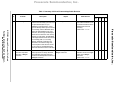
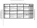
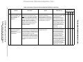
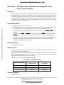
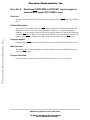
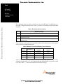
Freescale Semiconductor, Inc.
Errata
MPC8240CE
Rev. 5, 1/2004
Freescale Semiconductor, Inc...
MPC8240
Integrated Processor
Chip Errata
This document details all known silicon errata for the MPC8240. The MPC8240 is a
PowerPC™ integrated microprocessor. Table 1 provides a revision history for this chip errata
document.
Table 1. Document Revision History
Rev. No.
0–2.8
Significant Changes
Earlier releases of document.
3
Added Errors 21–23.
4
Added Errors 24–26.
5
Deleted Error 24 (duplicate of Error 18) and renumbered errors.
Added Error 26.
Table 2 provides a cross-reference to match the revision code in the processor version register
to the revision level marked on the part.
Table 2. Revision Level to Part Marking Cross-Reference
MPC8240
Revision
Part Marking
Processor Version
Register
Revision ID
Register
1.1
B
0x00810101
0x11
1.11
C
0x00810101
0x11
1.2
D
0x00810101
0x12
1.3
E
0x00810101
0x13
Table 3 summarizes all known errata and lists the corresponding silicon revision level to
which the erratum applies. A ‘Y’ entry indicates that the erratum applies to a specific revision
level, and a dash (‘—’) entry means that the erratum does not apply.
For More Information On This Product,
Go to: www.freescale.com
Freescale Semiconductor, Inc...
Table 3. Summary of Silicon Errata and Applicable Revision
Silicon Revision
No.
Problem
Description
Impact
Work Around
1.1 1.11 1.2
1.3
PCI streaming
PCI master issues a lock write that
System hangs.
crosses cache boundary (see PCI Local
Bus Specification (Rev. 2.1) for
establishing lock transaction). If PCI
logic has already written up to the cache
line boundary, and the MPC8240 write
buffers are still available for the next
cache line, the PCI logic will attempt to
stream the next cache line into memory.
However, for lock writes, the MPC8240
as the target will disconnect at the cache
line boundary (that is, no crossing
allowed), effectively ending the PCI
transaction. Since the PCI logic has
issued request to write the next cache
line into memory, the MPC8240 write
buffers will wait forever for the write data.
Software should not use PCI
lock writes transaction or do
not issue transactions to the
MC8240 that cross 4K
boundary.
Fixed in Rev. 1.1 = C.
Y
—
—
—
2
CPU instruction
execution stops after
execution of tlbsync
instruction
The TLBISYNC signal to the MPC8240 System will hang when executing a
internal processor is always asserted,
tlbsync instruction.
which indicates that CPU instruction
execution should stop after execution of
a tlbsync instruction
Fixed in Rev. 1.1 = C.
Software should use a sync
rather than a tlbsync
instruction.
Fixed in Rev. 1.1 = C.
Y
—
—
—
Freescale Semiconductor, Inc.
MPC8240 Integrated Processor Chip Errata
For More Information On This Product,
Go to: www.freescale.com
1
Freescale Semiconductor, Inc...
Table 3. Summary of Silicon Errata and Applicable Revision (continued)
Silicon Revision
No.
Problem
Description
Impact
Work Around
1.1 1.11 1.2
1.3
ROM three-stated wait
When the ROM three-stated wait
functionality in EDO/FPM counter is programmed to a non-zero
systems
value for EDO/FPM systems, there
exists a cycle window between the
completion of a single-beat ROM read
and the assertion of the three-state wait
interval. During this window, the central
control unit (CCU) can issue a DRAM
transfer to the memory control unit
(MCU) in violation of the programmed
three-state wait period. Potentially, this
may result in a three-stated collision on
the memory data bus when the DRAM
device subsequently tries to drive read
data onto the bus before a slow ROM
device relinquishes control of it.
Three-stated collisions on the
memory data bus for EDO/FPM
memory systems with slow ROM,
Flash, or Port X devices.
For EDO/FPM memory
systems, program ROM
three-state wait counter in
memory configuration control
registers to zero. (that is,
disable it).
Y
Y
Y
Y
4
Write-thru stores followed The sequence of the write-thru stores
The write-thru store is completed
by dcbz followed by
followed by snoop all to same line cache. after the dcbz instruction.
snoop
This occurs when the logical address for
the dcbz and the write-thru store are
different but aliased to the same physical
page.
Do not rely on dcbz to zero
cache lines in areas of
memory that are marked as
write-thru and can be
accessed via multiple logical
addresses. Storing of zeros
could be used instead.
Y
Y
Y
Y
5
Broadcasting of dcbz
instructions
Disable the broadcasting of
dcbz by marking the memory
space being addressed by
the dcbz instruction as not
global in the BAT or PTE.
Y
Y
Y
Y
A sequence of broadcasting dcbz
Snoop originator may timeout
instructions may retry snoop indefinitely. and/or cause the snooped
transaction to never complete.
Freescale Semiconductor, Inc.
MPC8240 Integrated Processor Chip Errata
For More Information On This Product,
Go to: www.freescale.com
3
Freescale Semiconductor, Inc...
Table 3. Summary of Silicon Errata and Applicable Revision (continued)
Silicon Revision
No.
Problem
Description
Impact
Work Around
1.1 1.11 1.2
PCI latency timer
expiration with target
disconnect causes data
corruption
7
8
The MPC8240 as a master is doing a
Data corruption can occur.
read or write on the PCI bus and its
latency timer expires and the MPC8240
grant is taken away, the MPC8240 is
forced off the PCI bus and will restart the
next transaction, the next time it has
access to the PCI bus. If in the last beat
of data transfer, a stop is asserted and
the data is transferred, the MPC8240 will
put out the wrong address for the next
transaction. The result is data corruption.
This can happen for processor to PCI
read/write or DMA read/write
transactions on the PCI bus.
For processor-to-PCI
transactions, increasing the
latency value to a higher
value (0x48 or more) will
solve the data corruption
problem.
For DMA-to-PCI operations,
increasing the latency value
to a higher value (0x48 or
more) and set the DMA mode
register’s bit 23:22 to b’01.’
Note that the DMA engine is
operating with reduced PCI
performance in this mode.
Fixed in Rev. 1.2 = D.
Y
Y
—
—
Direct configuration write If Map A is used and software tries to use Unable to perform direct method
accesses to PCI device in direct configuration write to PCI devices, configuration write to PCI devices
Map A
the transaction will come out to the PCI in Map A.
bus as an I/O write cycles. Note that
direct method configuration reads from
PCI devices functions properly.
Software can use the indirect
method configuration write
access to access in Map A to
configure the PCI devices.
Fixed in Rev. 1.2 = D.
Y
Y
—
—
Read from 0xFFF002000xFFF00207 cannot
negate an asserted MCP
signal if PCI ROM is used
The machine check
exception handler can
perform a dummy read from
0x00000200 in order to
negate the MCP signal.
Y
Y
Y
Y
If the processor core detects an asserted Unable to negate MCP signal by
MCP and this results in a machine check opcode fetch from location
interrupt, the MPC8240 will issue a code 0xFFF00200 if PCI ROM is used.
fetch from 0xFFF00200 if MSR[IP] = 1 or
from 0x00000200 if MSR[IP] = 0. Upon
seeing the fetch from the MCP exception
handler, the MPC8240 should then
negate the MCP signal. However, if the
address 0xFFF00200 is used while
ROM is located in PCI memory space
(RCS0 = 0 during reset), this read
operation will not negate the MCP signal.
Freescale Semiconductor, Inc.
MPC8240 Integrated Processor Chip Errata
For More Information On This Product,
Go to: www.freescale.com
6
1.3
Freescale Semiconductor, Inc...
Table 3. Summary of Silicon Errata and Applicable Revision (continued)
Silicon Revision
No.
Problem
Description
Impact
Work Around
1.1 1.11 1.2
9
DLL_RESET bit must be
toggled by system
software during
initialization to ensure
DLL clock functionality
DLL clocks not guaranteed to
function unless this bit is toggled; if
not performed, DLL clocks may
intermittently not function resulting
in no clock outputs on the
SDRAM_CLK[0:3] or
SDRAM_SYNC_OUT signals and
thus, resulting in a system hang.
System software (boot code)
must toggle the DLL_RESET
bit, bit 5 of the Address Map B
Options Register (AMBOR)
0xEO, during reset-start up
initialization.
—
Y
Y
Y
10 PCI multiple-beat write
with starting address in
the last 4 bytes of a 4K
block can cause data
corruption
PCI multiple-beat write with starting
System hangs or data corruption
address in the last 4 bytes of a 4K block can occur.
can cause data corruption.
Software should not issue
multiple-beat PCI writes to an
address that starts within the
last 4 bytes of a 4K boundary.
Fixed in Rev. 1.2 = D.
—
Y
—
—
11
Twelve signals are not included on the
BSDL scan chain. They are:
MIV, PCI_CLK(0-3), PCI_SYNC_OUT,
PCI_CLK4/DA3, SDRAM_SYNC_OUT,
SDRAM_CLK(0-3)
In addition, the LVDD and OVDD power
pins are not on the BSDL.
Add a functional test to board
level testing for verification of
the clock outs. MIV is used as
a prototype bring-up feature
and most likely not used for
production.
Y
Y
Y
Y
Non-compliant IEEE
1149.1 boundary scan
Twelve out of 220 functional pins
are not supported on the BSDL
scan chain; therefore, JTAG
interface cannot interconnect test
>5% of the pins. SDRAM interface
testing capability may be impacted
since SDRAM_CLK pins are
affected by this errata.
Freescale Semiconductor, Inc.
MPC8240 Integrated Processor Chip Errata
For More Information On This Product,
Go to: www.freescale.com
The DLL_RESET bit, bit 5 of the Address
Map B Options Register (AMBOR)
0xEO, must be toggled
(logic 0—logic 1—logic 0) by the system
software (boot code) during initialization
before SDRAM clocks are guaranteed to
function.
1.3
Freescale Semiconductor, Inc...
Table 3. Summary of Silicon Errata and Applicable Revision (continued)
Silicon Revision
No.
Problem
Description
Impact
Work Around
1.1 1.11 1.2
1.3
When the on-chip PCI arbiter is disabled,
GNT(0) will function as the bus request
from the MPC8240 to the external PCI
arbiter in order to get ownership of the
PCI bus. However, due to the existence
of a logic error, there is a double output
valid delay for this output signal. This is
caused by the logic having twice as
many delay elements as required
between the latch and the output pin.
Note: these additional delay elements
are controlled by the
PCI_HOLD_DELAY(0:2) bits (bits 6–4 of
the PMC Register 2 <0x72>).
Systems using an external PCI
arbiter may encounter a GNT(0)
signal output valid timing problem
(output valid time > 6.0 ns) when
operating the PCI bus at 66 MHz
even if PCI_HOLD_DELAY(0:2) =
000 to minimize the output valid
time.
None
Y
Y
—
—
13 Dual PLL bypass mode
not functioning
When PLL_CFG[0:4] is configured for
PLL_CFG[0:4] = 00110, dual PLL
00110, the MPC8240 does not boot. This bypass mode is not a valid
configuration bypasses both the
selection for the MPC8240.
peripheral logic PLL and the CPU logic
PLL. With the CPU PLL bypassed, there
is no synchronization feedback
mechanism to maintain the phase
relationship between the MPC8240
internal peripheral logic’s sys_logic_clk
and the CPU internal clock. The CPU
bus clock is skewed with respect to the
peripheral logic’s sys_logic_clk resulting
in the MPC8240 not being able to
operate in the dual PLL bypass mode.
None
Y
Y
Y
Y
Freescale Semiconductor, Inc.
MPC8240 Integrated Processor Chip Errata
For More Information On This Product,
Go to: www.freescale.com
12 GNT(0) has double
output valid delay
Freescale Semiconductor, Inc...
Table 3. Summary of Silicon Errata and Applicable Revision (continued)
Silicon Revision
No.
Problem
Description
Impact
Work Around
1.1 1.11 1.2
1.3
The MPC8240 corrupts inbound
data/instructions when bursting into
cache from PCI space. Single-beat
transfers from PCI to processor will not
be affected.
Users of the MPC8240 should not
use bursting from PCI space.
Perform single-beat
transactions when reading
from PCI space. This can be
accomplished by marking the
PCI space as
cache-inhibited. If 32-bit
mode is used, only
single-beat reads from PCI
without crossing the word
boundary is allowed.
Otherwise, the access will
result in a burst of 2 beats
and the processor may get
corrupt data.
Use DMA engine to move
data to/from PCI space to
main memory, then cache
(burst read) the memory into
the processor.
Fixed in Rev 1.2 = D.
Y
Y
—
—
15 DMA double write only
last PCI beat.
For certain programmed values of the
DMA’s DAR (Destination Address
Register) and DMA’s BCR (Byte Count
Register), the DMA controller will write
the last beat of data out twice on the PCI
bus.
The double write may cause
difficulty for FIFO-like structures on
the PCI bus. No problem is
expected for normal memory map
devices on the PCI bus.
Software should try to avoid
programming the
combination of DAR and BCR
if the PCI device has difficulty
in receiving the double write.
Fixed in Rev. 1.2 = D.
Y
Y
—
—
Freescale Semiconductor, Inc.
MPC8240 Integrated Processor Chip Errata
For More Information On This Product,
Go to: www.freescale.com
14 Data corruption when
bursting from PCI
Freescale Semiconductor, Inc...
Table 3. Summary of Silicon Errata and Applicable Revision (continued)
Silicon Revision
No.
Problem
Description
Impact
Work Around
1.1 1.11 1.2
If certain conditions occur when the
MPC8240 is not the target of a PCI
transaction, the MPC8240 will oscillate
SERR. Two cycles after the detected
event, the MPC8240 will always assert
DEVSEL for one cycle. After the
DEVSEL assertion, the internal state
machine may lose state and may not
respond to any accesses from an
external PCI master.
This is a problem when the
MPC8240 is operating in
peripheral (agent) mode and is a
potential problem in host mode if
the IDSEL pin of the MPC8240 is
not pulled down to a logic 0.
17 DMA may execute
incorrect PCI last beat
because of PCI
transactions not involving
the MPC8240
For PCI transfers initiated by the
System may hang or data
MPC8240 DMA, if the DMA transfer has corruption can occur.
one more beat to be completed (read or
write) and is waiting for the PCI bus and
another PCI master is currently
transferring data to another PCI target,
the DMA transfer for the last beat will not
put out the correct cycle on the PCI bus
the next time the MPC8240 is granted
the bus.
In host mode, we recommend
to pulldown the IDSEL input
on the MPC8240. In
peripheral mode, external
logic needs to be added to
qualify the IDSEL input to the
MPC8240 in such a way
where the IDSEL input will
not be asserted after the
address phase of any PCI
transaction.
Fixed in Rev. 1.3 = E.
Y
Y
Y
—
For a PCI memory target that
can accept burst transfers
without disconnecting at
non-cache line boundaries,
there are precautionary
programming steps which
can be taken for DMA
transactions accessing PCI.
There is no work around for a
PCI memory target which
cannot handle burst transfers
without disconnecting at
non-cache line boundaries.
Fixed in Rev. 1.3 = E.
Y
Y
Y
—
Freescale Semiconductor, Inc.
MPC8240 Integrated Processor Chip Errata
For More Information On This Product,
Go to: www.freescale.com
16 MPC8240 may
misinterpret IDSEL during
a PCI transaction that
does not involve
MPC8240
1.3
Freescale Semiconductor, Inc...
Table 3. Summary of Silicon Errata and Applicable Revision (continued)
Silicon Revision
No.
Problem
Description
Impact
Work Around
1.1 1.11 1.2
18 stfd of uninitialized FPR
can hang part
Upon coming out of reset,
initialize all the FPRs which
will be used; the value used
for initialization is not
important.
Fixed in documentation.
Y
Y
Y
Y
19 PCI input high voltage for MPC8240 devices do not meet PCI
MPC8240 not PCI
Local Bus Specification (Rev. 2.1)
2.1-compliant
minimum input high voltage (VIH) DC
electrical characteristic specification; the
minimum PCI 2.1 input high voltage
specification is 0.5 × OVDD, where OVDD
has a range of 3.0–3.6 V DC. See
Table 3 in the MPC8240 Integrated
Processor Hardware Specification.
Currently, MPC8240 devices have a
minimum input high voltage of
0.65 × OVDD.
Systems with PCI devices capable
of only driving the PCI specified
minimum VIH (0.5 × OVDD ≤ min
VIH < 0.65 × OVDD) cannot
interface to the MPC8240.
Ensure other PCI devices in
the system with the
MPC8240 are capable of
driving minimum VIH ≥ 0.65 ×
OVDD.
Y
Y
Y
Y
20 Non-PCI input high
MPC8240 devices do not meet standard
voltage for MPC8240 not TTL specification minimum input high
TTL-compatible
voltage (VIH) DC electrical characteristic
specification; the minimum input high
voltage specification is 2.0 V DC. See
Table 3 in the MPC8240 Integrated
Processor Hardware Specification.
Currently, MPC8240 devices have a
minimum input high voltage of 2.25 V.
Systems with devices capable of
only driving the TTL minimum VIH
(2.0 V ≤ minimum VIH < 2.25 V)
cannot interface to the MPC8240.
Ensure other devices in the
system with the MPC8240
are capable of driving
minimum VIH ≥ 2.25 V.
Y
Y
Y
Y
Freescale Semiconductor, Inc.
MPC8240 Integrated Processor Chip Errata
For More Information On This Product,
Go to: www.freescale.com
The 64-bit FPRs each have additional
This affects all systems which use
internal bits associated with them which floating point operations.
specify the type of floating point number
contained in the register. These bits get
properly set whenever the FPR is
loaded. However, it is possible for the
part to power up with the internal bits
randomly set such that storing the FPR
with an stfd instruction before the
internal bits are corrected via a floating
point load operation will result in the
device hanging.
1.3
Freescale Semiconductor, Inc...
Table 3. Summary of Silicon Errata and Applicable Revision (continued)
Silicon Revision
No.
Problem
Description
Impact
Work Around
1.1 1.11 1.2
This problem occurs on the
MPC8240 when working in ECC
(where RMW has to be on), or
normal parity modes, and CPU
data gets corrupted in a single-beat
60x write transaction.
All CPU-to-local memory
writes that require error
reporting should be burst
writes (cacheable, write-back
accesses). This work around
cannot be implemented for
transactions that involve I/O
devices that may not have
caching capability.
Y
Y
Y
Y
22 Type 2 fast back-to-back If a PCI master issues a type 2 fast
Type 2 fast back-to-back
transactions result in data back-to-back transaction to the
transactions are not supported on
corruption
MPC8240, the transaction results in data the MPC8240.
corruption. This is the case for both read
and write transactions.
Software should disable the
ability to run fast
back-to-back transactions on
PCI master devices that can
issue fast back-to-back
transactions to the
MPC8240.
Y
Y
Y
Y
23 Enabling the detection of Setting bit 6 of the Error Enabling
SERR assertions that occur by an None
PCI SERR does not work Register 2 (0xC4) does not report SERR external PCI agent are not reported
assertions that occur on the PCI bus at by the MPC8240.
any time, regardless of whether the
MPC8240 is the initiator, the target, or a
non-participating agent.
Y
Y
Y
Y
24 MPC8240 does not
The MPC8240 fails to detect the
detect assertion of PERR assertion of the PERR signal when the
signal for a certain case following conditions are met:
The memory-to-PCI clock ratio is 2:1 or
higher (for example, 2:1, 3:1, and 4:1).
The MPC8240 is the initiator of the PCI
bus transaction.
A parity error occurs in the last data
transfer of the transaction (for either
single- or multiple-beat transactions).
Y
Y
Y
Y
The MPC8240 fails to detect the
assertion of PERR and does not
report the parity error to the core
via the internal mcp signal.
Potentially corrupt data may be
propagated.
None
Freescale Semiconductor, Inc.
MPC8240 Integrated Processor Chip Errata
For More Information On This Product,
Go to: www.freescale.com
21 Data parity errors on 60x MCP8240 fails to detect the write-parity
bus single-beat writes are errors and does not invoke a machine
not detected
check error if all of the following
conditions are met:
• A single beat 60x write is being
performed.
• The CPU bus has corrupted data.
• RMW parity mode is turned on
(MCCR2[RMW_Par] is set).
• Either ECC or parity modes are
enabled.
1.3
Freescale Semiconductor, Inc...
Table 3. Summary of Silicon Errata and Applicable Revision (continued)
Silicon Revision
No.
Problem
Description
Impact
Work Around
1.1 1.11 1.2
1.3
The MPC8240 fails to detect the
The MPC8240 fails to detect an
assertion of the MCP signal whether in MCP in this case.
host or agent mode when bit 31 of the
Inbound Doorbell register (IDBR) is set,
even if the requirements for an MCP are
met.
Use interrupts in the
messaging unit to generate
an MCP.
Y
Y
Y
Y
26 PCI writes may not
invalidate speculative
read data
This error may occur when an incoming Potentially stale data may be
PCI read has triggered a prefetch for the returned for PCI reads.
next cache line.
Currently there are two work
arounds:
1. Insert a dummy PCI read
from an unrelated memory
location between the PCI
write and the desired PCI
read sequence.
2. Turn off speculative
reading by clearing PICR1[2]
and prevent external PCI
masters from issuing
memory-read-multiple
commands.
Y
Y
Y
Y
Freescale Semiconductor, Inc.
MPC8240 Integrated Processor Chip Errata
For More Information On This Product,
Go to: www.freescale.com
25 MPC8240 does not
detect assertion of MCP
signal for a certain
doorbell register case in
the messaging unit
Freescale Semiconductor, Inc.
Error No. 1: PCI streaming
Overview:
A fix for PCI streaming write (see Errata No. 3 for Rev.1.0) causes PCI lock writes and writes that
cross 4K boundary to hang. There should be no impact for systems that do not use PCI lock write
transactions to the MPC8240 or do not issue writes to the MPC8240 that cross 4K boundary.
Freescale Semiconductor, Inc...
Detailed Description:
PCI master issues a lock write that crosses cache boundary (see PCI Local Bus Specification
(Rev. 2.1) for establishing lock transaction). If PCI logic has already written up to the cache line
boundary, and the MPC8240 write buffers are still available for the next cache line, the PCI logic
will attempt to stream the next cache line into memory. However, for lock writes, the MPC8240 as
the target will disconnect at the cache line boundary (that is, no crossing allowed), effectively
ending the PCI transaction. Since the PCI logic has issued request to write the next cache line into
memory, the MPC8240 write buffers will wait forever for the write data. The result is a system
hang. The same failure is also observed in the case of crossing 4K boundary PCI writes. The
MPC8240 as a target will issue disconnect at the 4K boundary (that is, no crossing allowed). If the
MPC8240 write buffers are available for the next cache line crossing the 4K boundary, then the
logic will also attempt to stream the next cache line into memory. The result is also a hang.
Projected Impact:
System hangs.
Work Arounds:
Software should not use PCI lock writes transaction or do not issue transactions to the MPC8240
that cross 4K boundary.
Projected Solution:
Fixed in Rev. 1.1 = C.
MPC8240 Integrated Processor Chip Errata
For More Information On This Product,
Go to: www.freescale.com
Freescale Semiconductor, Inc.
Error No. 2: CPU instruction execution stops after execution of
tlbsync instruction
Overview:
The system will hang upon executing a tlbsync instruction.
Detailed Description:
The TLBISYNC signal to the MPC8240 internal processor is always asserted, which indicates that
CPU instruction execution should stop after execution of a tlbsync instruction.
Projected Impact:
Freescale Semiconductor, Inc...
System will hang when executing a tlbsync instruction.
Work Arounds:
Software should use a SYNC instruction rather than a tlbsync instruction.
Projected Solution:
Fixed in Rev. 1.1 = C.
MPC8240 Integrated Processor Chip Errata
For More Information On This Product,
Go to: www.freescale.com
Freescale Semiconductor, Inc.
Error No. 3: ROM three-stated wait functionality in EDO/FPM systems
Overview:
ROM three-stated wait functionality not working for EDO/FPM systems.
Detailed Description:
Freescale Semiconductor, Inc...
When the ROM three-state wait counter is programmed to a non-zero value for EDO/FPM
systems, there exists a cycle window between the completion of a single-beat ROM read and the
assertion of the three-state wait interval. During this window, the central control unit (CCU) can
issue a DRAM transfer to the memory control unit (MCU) in violation of the programmed
three-state wait period. Potentially, this may result in a three-state collision on the memory data
bus when the DRAM device subsequently tries to drive read data onto the bus before a slow ROM
device relinquishes control of it.
Projected Impact:
Three-stated collisions on the memory data bus for EDO/FPM memory systems with slow ROM,
Flash, or Port X devices.
Work Arounds:
For EDO/FPM memory systems, program ROM three-state wait counter in memory configuration
control registers to zero (that is, disable it).
Projected Solution:
TBD
MPC8240 Integrated Processor Chip Errata
For More Information On This Product,
Go to: www.freescale.com
Freescale Semiconductor, Inc.
Error No. 4: Write-thru stores followed by dcbz followed by snoop
Overview:
Write-thru stores followed by dcbz followed by snoop all to same line cache, may cause
incoherence.
Detailed Description:
The sequence of the write-thru stores followed by snoop all to same line cache. This occurs when
the logical address for the dcbz and the write-thru store are different but aliased to the same
physical page.
Freescale Semiconductor, Inc...
Projected Impact:
The write-thru store is completed after the dcbz instruction.
Work Arounds:
Do not rely on dcbz to zero cache lines in areas of memory that are marked as write-thru and can
be accessed via multiple logical addresses. Storing of zeros could be used instead.
Projected Solution:
TBD
MPC8240 Integrated Processor Chip Errata
For More Information On This Product,
Go to: www.freescale.com
Freescale Semiconductor, Inc.
Error No. 5: Broadcasting of dcbz instructions
Overview:
The broadcasting of dcbz instructions may retry snoop accesses indefinitely.
Detailed Description:
A sequence of broadcasting dcbz instructions may retry snoop indefinitely.
Projected Impact:
Snoop originator may timeout and/or cause the snooped transaction to never complete.
Freescale Semiconductor, Inc...
Work Arounds:
Disable the broadcasting of dcbz by marking the memory space being addressed by the dcbz
instruction as not global in the BAT or PTE.
Projected Solution:
TBD
MPC8240 Integrated Processor Chip Errata
For More Information On This Product,
Go to: www.freescale.com
Freescale Semiconductor, Inc.
Error No. 6: PCI latency timer expiration with target disconnect
causes data corruption
Overview:
The MPC8240 as a master is doing a read or write on the PCI bus and its latency timer expires and
the MPC8240 grant is taken away, the MPC8240 is forced off the PCI bus and will restart the next
transaction, the next time it has access to the PCI bus. If in the last beat of data transfer, a stop is
asserted and the data is transferred, the MPC8240 will put out the wrong address for the next
transaction. The result is data corruption. This can happen for processor to PCI read/write or DMA
read/write transactions on the PCI bus.
Freescale Semiconductor, Inc...
Detailed Description:
The sequence of operation is as followed:
1. The MPC8240 starts a transaction on the PCI bus and the MPC8240’s grant is taken away. The
MPC8240’s latency timer expires and the MPC8240 still has more data to transfer.
2. The MPC8240 has to terminate the current transaction by deasserting FRAME. IRDY is still
asserted.
3. The target asserts STOP and TRDY for the last beat. Note that STOP is asserted only when
FRAME is deasserted and continues for one PCI cycle. Data is transferred during this time.
4. The MPC8240 finishes the current transaction and waits for the arbiter to grant the bus again.
5. Once grant is given to the MPC8240, the MPC8240 resumes the previously terminated
transaction, but the address is incorrect.
Projected Impact:
Data corruption can occur.
Work Arounds:
For processor-to-PCI transactions, increasing the latency value to a higher value (0x48 or more)
will solve the data corruption problem.
For DMA operations involving PCI, increasing the latency value to a higher value (0x48 or more)
and set the DMA Mode Register’s bit 23:22 to b’01.’ Note that the DMA engine is operating with
reduced PCI performance in this mode. See Table 4.
Example: 33 MHz PCI and 100 MHz memory system
Table 4. Memory—PCI DMA Transfer
Measurement Platform
Errata No. 6 Work Around
Not Implemented
Errata No. 6 Work Around
Implemented
Simulation
127 MBytes/s
—
Test Card
124 MBytes/s
51 MBytes/s
Reference System
98 MBytes/s
56 MBytes/s
Projected Solution:
Fixed in Rev.1.2 = D.
MPC8240 Integrated Processor Chip Errata
For More Information On This Product,
Go to: www.freescale.com
Freescale Semiconductor, Inc.
Error No. 7: Direct configuration write accesses to PCI device in
Map A
Overview:
Cannot perform direct configuration write accesses to PCI devices if MPC8240 is configured for
Map A.
Freescale Semiconductor, Inc...
Detailed Description:
A subset of the MPC8240 configuration registers are accessible from the PCI bus through the use
of PCI configuration cycles using either a direct or indirect access method. If Map A is used and
software attempts to perform a direct method configuration write to PCI devices, the transaction
will come out to the PCI bus as an I/O write cycle. Note that direct method configuration reads
from PCI devices functions properly.
Projected Impact:
Unable to perform direct method configuration write to PCI devices in Map A.
Work Arounds:
Software can use the indirect method configuration write access in Map A to configure the PCI
devices.
Projected Solution:
Fixed in Rev. 1.2 = D.
MPC8240 Integrated Processor Chip Errata
For More Information On This Product,
Go to: www.freescale.com
Freescale Semiconductor, Inc.
Error No. 8: Read from 0xFFF00200–0xFFF00207 cannot negate an
asserted MCP signal if PCI ROM is used
Overview:
Reading from 0xFFF00200–0xFFF00207 does not negate an asserted MCP signal if PCI ROM is
used.
Freescale Semiconductor, Inc...
Detailed Description:
If the processor core detects an asserted MCP and this results in a machine check interrupt, the
MPC8240 will issue a code fetch from 0xFFF00200 if MSR[IP] = 1 or from 0x00000200 if
MSR[IP] = 0. Upon seeing the fetch from the MCP exception handler, the MPC8240 should then
negate the MCP signal. However, if the address 0xFFF00200 is used while ROM is located in PCI
memory space (RCS0 = 0 during reset), this read operation will not negate the MCP signal.
Projected Impact:
Unable to negate MCP signal by opcode fetch from location 0xFFF00200 if PCI ROM is used.
Work Arounds:
The machine check exception handler can perform a dummy read from 0x00000200 in order to
negate the MCP signal.
Projected Solution:
Document software requirement in the MPC8240 Integrated Processor User’s Manual.
MPC8240 Integrated Processor Chip Errata
For More Information On This Product,
Go to: www.freescale.com
Freescale Semiconductor, Inc.
Error No. 9: DLL_RESET bit must be toggled by system software
during initialization to ensure DLL clock functionality
Overview:
DLL_RESET bit must be toggled by system software during initialization to ensure DLL clock
functionality.
Detailed Description:
Freescale Semiconductor, Inc...
The DLL_RESET bit, bit 5 of the Address Map B Options Register (AMBOR) 0xEO, must be
toggled (logic 0—logic 1—logic 0) by the system software (boot code) during initialization before
SDRAM clocks are guaranteed to function.
Projected Impact:
DLL clocks not guaranteed to function unless this bit is toggled; if not performed, DLL clocks
may intermittently not function resulting in no clock outputs on the SDRAM_CLK[0-3] or
SDRAM_SYNC_OUT signals and thus resulting in a system hang.
Work Arounds:
System software (boot code) must toggle the DLL_RESET bit, bit 5 of the Address Map B
Options Register (AMBOR) 0xEO, during reset-start up initialization.
Projected Solution:
Document software requirement in the MPC8240 Integrated Processor User’s Manual.
MPC8240 Integrated Processor Chip Errata
For More Information On This Product,
Go to: www.freescale.com
Freescale Semiconductor, Inc.
Error No. 10: PCI multiple-beat write with starting address in the last
4 bytes of a 4K block can cause data corruption
Overview:
PCI multiple-beat write with starting address in the last 4 bytes of a 4K block can cause data
corruption.
Detailed Description:
A PCI-write-to-local memory that starts at an address within the last 4 bytes of a 4K block and
writing across the 4K boundary (multiple-beat transaction) can cause data corruption. The scenario
is as follows:
Freescale Semiconductor, Inc...
PCMWB buffers are empty.
and
A PCI master does a multiple-beat write which starts at an address within the last 4 bytes of a
4K block.
and
The MPC8240 claims the PCI write transaction and after the address phase, the assertion of
IRDY by the master occurs after the first assertion of the MPC8240 TRDY.
then
The MPC8240 does a disconnect on the PCI bus (by design due to the 4K boundary) but
internally, because of an errata in the logic, it still sends out a write request to the internal
buffers causing data corruption.
Note that if the starting address is not within the last word of a 4K block or if IRDY asserts at the
same time as TRDY or before TRDY, the problem does not occur.
Projected Impact:
System hangs or data corruption can occur.
Work Arounds:
Software should not issue multiple-beat PCI writes to an address that starts within the last 4 bytes
of a 4K boundary.
Projected Solution:
Fixed in Rev. 1.2 = D.
MPC8240 Integrated Processor Chip Errata
For More Information On This Product,
Go to: www.freescale.com
Freescale Semiconductor, Inc.
Error No. 11: Non-compliant IEEE 1149.1 boundary scan
Overview:
The MPC8240 BSDL scan chain does not comply with IEEE 1149.1 specifications.
Detailed Description:
Twelve signals are not included on the BSDL scan chain. They are:
MIV
PCI_CLK(0–3)
PCI_SYNC_OUT
Freescale Semiconductor, Inc...
PCI_CLK4/DA3
SDRAM_SYNC_OUT
SDRAM_CLK(0–3)
In addition, the LVDD and OVDD power pins are not on the BSDL.
Projected Impact:
Twelve out of 220 functional pins are not supported on the BSDL scan chain; therefore, JTAG
interface cannot interconnect test >5% of the pins. SDRAM interface testing capability may be
impacted since SDRAM_CLK pins are affected by this errata.
Work Arounds:
Add a functional test to board level testing for verification of the clock outs. MIV is used as a
prototype bring-up feature and most likely not used for production.
Projected Solution:
IEEE 1149.1 non-compliance documented in BSDL file: MPC8240.R1C.
MPC8240 Integrated Processor Chip Errata
For More Information On This Product,
Go to: www.freescale.com
Freescale Semiconductor, Inc.
Error No. 12: GNT(0) has double output valid delay
Overview:
GNT(0) has double output valid delay when the on-chip PCI arbiter is disabled.
Detailed Description:
When the on-chip PCI arbiter is disabled, GNT(0) will function as the bus request from the
MPC8240 to the external PCI arbiter in order to get ownership of the PCI bus. However, due to the
existence of a logic error, there is a double output valid delay for this output signal.
Freescale Semiconductor, Inc...
This is caused by the logic having twice as many delay elements as required between the latch and
the output pin. Note: these additional delay elements are controlled by the
PCI_HOLD_DELAY(0:2) bits (bits 6–4 of the PMC Register 2 <0x72>).
Projected Impact:
Systems using an external PCI arbiter may encounter a GNT(0) signal output valid timing problem
(output valid time > 6.0 ns) when operating the PCI bus at 66 MHz even if
PCI_HOLD_DELAY(0:2) = 000 to minimize the output valid time.
Work Arounds:
None
Projected Solution:
Fixed in Rev.1.2 = D.
MPC8240 Integrated Processor Chip Errata
For More Information On This Product,
Go to: www.freescale.com
Freescale Semiconductor, Inc.
Error No. 13: Dual PLL bypass mode not functioning
Overview:
MPC8240 does not boot in the dual PLL bypass mode.
Detailed Description:
Freescale Semiconductor, Inc...
When PLL_CFG[0:4] is configured for 00110, the MPC8240 does not boot. This configuration
bypasses both the peripheral logic PLL and the CPU logic PLL and is supposed to result in the
MPC8240 operating in a 1:1:1 ratio mode for PCI:sys_logic_clk/MEM:CPU. However, with the
CPU’s PLL bypassed, there is no synchronization feedback mechanism to maintain the phase
relationship between the MPC8240 internal peripheral logic’s sys_logic_clk and the CPU’s
internal clock. Consequently, the CPU bus clock is skewed with respect to the peripheral logic’s
sys_logic_clk resulting in the MPC8240 not being able to operate in the dual PLL bypass mode.
Projected Impact:
PLL_CFG[0:4] = 00110, dual PLL bypass mode is not a valid selection for the MPC8240.
Work Arounds:
None
Projected Solution:
Remove references to this PLL_CFG[0:4] mode of operation from the MPC8240 Integrated
Processor Hardware Specifications (Rev. 0.3) and mark this setting as reserved.
MPC8240 Integrated Processor Chip Errata
For More Information On This Product,
Go to: www.freescale.com
Freescale Semiconductor, Inc.
Error No. 14: Data corruption when bursting from PCI
Overview:
MPC8240 corrupts inbound data when bursting from PCI space.
Detailed Description:
The MPC8240 corrupts inbound data/instructions when bursting into cache from PCI space.
Single-beat transfers from PCI to processor will not be affected.
Projected Impact:
Freescale Semiconductor, Inc...
Users of the MPC8240 should not use bursting from PCI space.
Work Arounds:
Perform single-beat transactions when reading from PCI space. This can be accomplished by
marking the PCI space as cache-inhibited. If 32-bit mode is used, only single-beat reads from PCI
without crossing the word boundary is allowed. Otherwise, the access will result in a burst of
2 beats and the processor may get corrupt data.
Use DMA engine to move data to/from PCI space to main memory, then cache (burst read) the
memory into the processor.
Projected Solution:
Fixed in Rev. 1.2 = D.
MPC8240 Integrated Processor Chip Errata
For More Information On This Product,
Go to: www.freescale.com
Freescale Semiconductor, Inc.
Error No. 15: DMA double write only last PCI beat
Detailed Description:
For certain programmed values of the DMA’s DAR (Destination Address Register) and DMA’s
BCR (Byte Count Register), the DMA controller will write the last beat of data out twice on the
PCI bus when the DMA engine is programmed either in local memory to PCI memory or PCI
memory to PCI memory transfer mode. No data corruption occurs when this double write happens,
and the status register updates normally after the second beat write has completed. The
combination of DAR and BCR that results in the double write can be determined as follows:
(DAR + BCR) mod 0x20 = R, where R is a number between 0x00 and 0x1F.
If R = 0x09 – 0x0C, 0x19 – 0x1C, or 0x11 – 0x14, then the double write occurs.
Freescale Semiconductor, Inc...
Example 1: DMA 42(decimal) bytes from 0x0000_0000 to 0x8000_0000.
R = (DAR + BCR) mod 0x20
R = (0x8000_0000 + 0x2A) mod 0x20
R = (2,147,483,648d + 42d) mod 32d
R = 10d = 0x0A
R = 0x0A which is in the range of 0x09–0x0C; therefore, double write of last beat to PCI
will occur.
Example 2: DMA 50(decimal) bytes from 0x0009_0000 to 0x0009_4FE0.
R = (DAR + BCR) mod 0x20
R = (0x0009_4FE0 + 0x32) mod 0x20
R = (610,272d + 50d) mod 32d
R = 18d = 0x12
R = 0x12 which is in the range of 0x11–0x14; therefore, double write of last beat to PCI will
occur.
Projected Impact:
The double write may cause difficulty for FIFO-like structures on the PCI bus. No problem is
expected for normal memory map devices on the PCI bus.
Work Arounds:
Software should try to avoid programming the DAR and BCR with the combination mentioned
above if the PCI device has difficulty in receiving the double write.
Projected Solution:
Fixed in Rev. 1.2 = D.
MPC8240 Integrated Processor Chip Errata
For More Information On This Product,
Go to: www.freescale.com
Freescale Semiconductor, Inc.
Error No. 16: MPC8240 may misinterpret IDSEL during a PCI
transaction that does not involve MPC8240
Overview:
When a PCI master is performing a transaction to some other PCI device, the MPC8240 may
interpret the transaction as a configuration cycle to the MPC8240.
This will happen during any cycle when:
FRAME is asserted, and
C/BE[3:0] is either b’1010’ or b’1011,’ and
IDSEL input to MPC8240 is asserted, and
Freescale Semiconductor, Inc...
AD[1:0] = b’00’ and AD[10:8] = b’000.’
If the above conditions occur while the MPC8240 is the target of the transaction, the MPC8240
will function as expected.
If the above conditions occur when the MPC8240 is not the target of the transaction, the MPC8240
will assert SERR if bit 8 of the PCI Command Register <0x04> is set. SERR will oscillate in this
manner: SERR will be driven low for two clocks and then three-stated for two clocks. The first
occurrence of SERR asserting will be three clocks after the detected event.
Regardless of whether bit 8 of the PCI Command Register <0x04> is set two cycles after the
detected event, the MPC8240 will always assert DEVSEL for one cycle. After the DEVSEL
assertion, the internal state machine may lose state and may not respond to any accesses from an
external PCI master.
Projected Impact:
This is a problem when the MPC8240 is operating in peripheral (agent) mode and is a potential
problem in host mode if the IDSEL pin of the MPC8240 is not pulled down to a logic 0.
Work Arounds:
In host mode, we recommend to pulldown the IDSEL input on the MPC8240. In general, this is an
acceptable solution for host mode operation as PCI configuration cycles are normally issued by the
host controller.
In peripheral mode, external logic needs to be added to qualify the IDSEL input to the MPC8240
in such a way where the IDSEL input will not be asserted after the address phase of any PCI
transaction. See Figure 1. This may introduce a timing problem as FRAME and IDSEL are
involved in order to generate the qualified IDSEL signal to the MPC8240 during the cycle when
FRAME transitions from logic 1 to logic 0. See Figure 2.
Projected Solution:
Fixed in Rev. 1.3 = E.
MPC8240 Integrated Processor Chip Errata
For More Information On This Product,
Go to: www.freescale.com
Freescale Semiconductor, Inc.
MPC8240
FRAME
PCI_SYNC_IN
D-FF
IDSEL_QUALIFIED
IDSEL
IDSEL (From PCI)
Figure 1. IDSEL Qualifying Logic
Freescale Semiconductor, Inc...
15 ns for 66 MHz PCI
30 ns for 33 MHz PCI
OVDD÷2
OVDD÷2
PCI_SYNC_IN
6 ns for 66 MHz PCI
6 ns margin for
clock skew, timeof-flight, and logic
gate propagation
3 ns for
66 MHz
PCI
IDSEL_QUALIFIED
IDSEL (ADx) @ 66 MHz
11 ns for 33 MHz PCI
* MPC8240 specifies 3 ns for PCI
Input Setup; therefore, there are
4 ns of additional margin for
logic gate propagation time.
12 ns margin for
clock skew, timeof-flight, and logic
gate propagation
7 ns* for
33 MHz
PCI
IDSEL_QUALIFIED
IDSEL (ADx) @ 33 MHz
Figure 2. Timing Diagram for IDSEL_QUALIFIED
MPC8240 Integrated Processor Chip Errata
For More Information On This Product,
Go to: www.freescale.com
Freescale Semiconductor, Inc.
Error No. 17: DMA may execute incorrect PCI last beat because of PCI
transactions not involving the MPC8240
Detailed Description:
For PCI transfers initiated by the MPC8240 DMA, if the DMA transfer has one more beat to be
completed (read or write) and is waiting for the PCI bus and another PCI master is currently
transferring data to another PCI target, the DMA transfer for the last beat will not put out the
correct cycle on the PCI bus the next time the MPC8240 is granted the bus.
The error condition is as follows:
1. The MPC8240 DMA has one more beat to transfer on the PCI bus. The ‘one more beat’
condition can be a result of either of the following:
Freescale Semiconductor, Inc...
a) The DMA is only performing a single beat transfer.
b) The DMA is currently requesting transfer of more than one beat (up to a cache line), and
the PCI target issues a disconnect to the MPC8240, such that the next time the MPC8240
is granted the PCI bus, there is only one remaining beat to transfer.
Note that the MPC8240 may have more data to transfer afterward, since the size of each
transfer (up to a cache line) depends on the DMA queue and number of bytes left to read or
write. Also, disconnecting at a cache line boundary is acceptable.
2. Another PCI master currently has mastering access on the PCI bus and transfers data to a PCI
target other than the MPC8240 that is currently waiting to transfer one more beat on the PCI
bus.
Note this errata does not occur if DMA has more than one beat waiting to be transferred when the
interfering cycle occurs, or if the interfering cycle is targeted toward the MPC8240 which has the
pending DMA transfer.
3. Then, if the MPC8240 is granted the bus it will try to transfer the last data beat.
Because of a logic error triggered by step 2, the MPC8240 will put out the wrong cycle on the PCI
bus. During this incorrect transaction any/all of the following may occur:
•
C/BE signals can be driven to an incorrect value (0x0 or 0xF) during the address and data
phases.
•
It is possible for the logic to reread the next to last beat even though it has already read it once.
•
The DMA status register may be incorrect (that is, the CB bit of the DSR is prematurely
terminated and the interrupt prematurely activated) if the condition occurs on the very last data
beat of a DMA PCI write transfer (that is, the DMA will finish transferring the last beat after
the CB bit is prematurely cleared and the interrupt has been activated).
Projected Impact:
System may hang or data corruption can occur.
Work Arounds:
For a PCI memory target which can accept burst transfers without disconnecting at noncache line
boundaries, the following programming steps should be taken for DMA transactions accessing
PCI:
1. Do not program the DMA to perform only a single-beat transfer.
MPC8240 Integrated Processor Chip Errata
For More Information On This Product,
Go to: www.freescale.com
Freescale Semiconductor, Inc.
2. Do not program the SAR/DAR registers to start at the last beat in a cache line and avoid
programming the SAR/DAR and BCR with values such that (SAR/DAR + BCR) mod 0x20 =
1, 2, 3, or 4.
3. The MPC8240 PCI latency timer should be programmed to 0x48 or higher and set the DMA
mode register’s reserved bits 23:22 to b01. Note that there will be a DMA performance
reduction when operating in this mode, since the MPC8240 will break up the DMA transaction
by transferring a single cache line at a time on the PCI bus.
There is no work around for a PCI memory target which cannot handle burst transfers without
disconnecting at noncache line boundaries (that is, single-beat disconnects or random
disconnects).
Projected Solution:
Freescale Semiconductor, Inc...
Fixed in Rev. 1.3 = E.
MPC8240 Integrated Processor Chip Errata
For More Information On This Product,
Go to: www.freescale.com
Freescale Semiconductor, Inc.
Error No. 18: stfd of uninitialized FPR can hang part
Detailed Description:
The 64-bit FPRs each have additional internal bits associated with them which specify the type of
floating-point number contained in the register. These bits are properly set whenever the FPR is
loaded. It is possible, however, for the part to power up with the internal bits randomly set such
that the FPR is interpreted as containing a denormalized number, but with the mantissa containing
all zeros. If this random state is stored with an stfd instruction before the internal bits are corrected
via a floating-point load operation, the part will hang while searching for a leading ‘1’ in the
mantissa.
Freescale Semiconductor, Inc...
The stfd instruction is the only instruction that causes this behavior.
Note that this problem was discovered when compiled code stored out FPRs in preparation for
using them as scratch registers early in the boot sequence.
Projected Impact:
This affects all systems that use floating-point operations.
Work Arounds:
When emerging from reset, initialize all the FPRs that will be used. The initialization value is not
important.
Projected Solution:
Fixed in documentation.
MPC8240 Integrated Processor Chip Errata
For More Information On This Product,
Go to: www.freescale.com
Freescale Semiconductor, Inc.
Error No. 19: PCI input high voltage for MPC8240 not PCI
2.1-compliant
Detailed Description:
MPC8240 devices do not meet the PCI Local Bus Specification (Rev 2.1), minimum input high
voltage (VIH) DC electrical characteristic specification; the minimum PCI 2.1 input high voltage
specification is 0.5 × OVDD, where OVDD has a range of 3.0–3.6 V DC. See Table 3 in the
MPC8240 Integrated Processor Hardware Specifications. Currently, MPC8240 devices have a
minimum input high voltage of 0.65 × OVDD.
Freescale Semiconductor, Inc...
Projected Impact:
Systems with PCI devices capable of only driving the PCI specified minimum VIH (0.5 × OVDD ≤
minimum VIH < 0.65 × OVDD) cannot interface to the MPC8240.
Work Arounds:
Ensure other PCI devices in the system with the MPC8240 are capable of driving minimum VIH ≥
0.65 × OVDD.
Projected Solution:
None
MPC8240 Integrated Processor Chip Errata
For More Information On This Product,
Go to: www.freescale.com
Freescale Semiconductor, Inc.
Error No. 20: Non-PCI input high voltage for MPC8240 not
TTL-compatible
Detailed Description:
MPC8240 devices do not meet standard TTL specification minimum input high voltage (VIH) DC
electrical characteristic specification; the minimum input high voltage specification is 2.0 V DC.
See Table 3 in the MPC8240 Integrated Processor Hardware Specifications. Currently, MPC8240
devices have a minimum input high voltage of 2.25 V.
Projected Impact:
Freescale Semiconductor, Inc...
Systems with devices capable of only driving the TTL minimum V IH (2.0 V ≤ minimum VIH <
2.25 V) cannot interface to the MPC8240.
Projected Solution:
None
Work Arounds:
Ensure other devices in the system with the MPC8240 are capable of driving minimum
VIH ≥ 2.25 V.
Projected Solution:
None
MPC8240 Integrated Processor Chip Errata
For More Information On This Product,
Go to: www.freescale.com
Freescale Semiconductor, Inc.
Error No. 21: Data parity errors on 60x bus single-beat writes are not
detected
Detailed Description:
MCP8240 fails to detect the write-parity errors and does not invoke a machine check error if all of
the following conditions are met:
•
A single-beat 60x write is being performed.
•
The CPU bus has corrupted data.
•
RMW parity mode is turned on (MCCR2[RMW_Par] is set).
•
Either ECC or parity modes are enabled.
Freescale Semiconductor, Inc...
Projected Impact:
This problem occurs on the MPC8240 when working in ECC (where RMW has to be on), or
normal parity modes, and CPU data gets corrupted in a single-beat 60x write transaction. As a
result, for ECC transactions, the corrupted data will be used to generate an ECC syndrome and
both will be written to SDRAM without detection. For normal parity mode, the corrupted data is
written into the SDRAM and the parity byte is recalculated for the entire line (with the corrupted
data) and also written into SDRAM.
For CPU burst write transactions, the problem does not occur for either ECC or parity modes.
Work Arounds:
All CPU-to-local memory writes that require error reporting should be burst writes (cacheable,
write-back accesses). This work around cannot be implemented for transactions that involve I/O
devices that may not have caching capability.
Projected Solution:
No plans to fix.
MPC8240 Integrated Processor Chip Errata
For More Information On This Product,
Go to: www.freescale.com
Freescale Semiconductor, Inc.
Error No. 22: Type 2 fast back-to-back transactions result in data
corruption
Detailed Description:
Type 2 fast back-to-back transactions are those that access multiple targets sequentially.
If a PCI master issues a type 2 fast back-to-back transaction to the MPC8240, the transaction
results in data corruption. This is the case for both read and write transactions.
Data that is read will be corrupted. Write transactions will write to incorrect locations or write bad
data to a specified location.
Projected Impact:
Freescale Semiconductor, Inc...
Type 2 fast back-to-back transactions are not supported on the MPC8240.
Work Arounds:
Software should disable the ability to run fast back-to-back transactions on PCI master devices that
can issue fast back-to-back transactions to the MPC8240. This can be done by clearing bit 9 of the
PCI Command Register in the master device.
Projected Solution:
No plans to fix.
MPC8240 Integrated Processor Chip Errata
For More Information On This Product,
Go to: www.freescale.com
Freescale Semiconductor, Inc.
Error No. 23: Enabling the detection of PCI SERR does not work
Detailed Description:
Enabling bit 6 of the Error Enabling Register 2 (0xC4) should report SERR assertions that occur
on the PCI bus at any time, regardless of whether the MPC8240 is the initiator, the target, or a
non-participating agent. This does not occur on the MPC8240, which results in bit 6 of the Error
Detection Register 2 (0xC5) not reporting any SERR assertions that occur on the PCI bus by an
external PCI agent.
Freescale Semiconductor, Inc...
Note that the reporting of a SERR assertion when it occurs on the PCI bus two clock cycles after
the address phase of transactions where the MPC8240 is the initiator, works as expected.
Therefore, if bit 7 of the Error Enabling Register 1 (ErrEnR1–0xC0) is set, and the case described
in the previous sentence occurs, the system error is reported in bit 7 of the Error Detection
Register 1 (ErrDR1–0xC1).
Projected Impact:
SERR assertions that occur by an external PCI agent are not reported by the MPC8240.
Work Arounds:
None
Projected Solution:
No plans to fix.
MPC8240 Integrated Processor Chip Errata
For More Information On This Product,
Go to: www.freescale.com
Freescale Semiconductor, Inc.
Error No. 24: MPC8240 does not detect assertion of PERR signal for a
certain case
Detailed Description:
The MPC8240 fails to detect the assertion of the PERR signal when all of the following conditions
are met:
•
The memory-to-PCI clock ratio is 2:1 or higher (for example, 2:1, 3:1, and 4:1).
•
The MPC8240 is the initiator of the PCI bus transaction.
•
A parity error occurs in the last data transfer of the transaction (for either single- or
multiple-beat transactions).
Freescale Semiconductor, Inc...
Projected Impact:
The MPC8240 fails to detect the assertion of PERR and does not report the parity error to the core
via the internal mcp signal. Potentially corrupt data may be propagated.
Work Arounds:
Use external logic to monitor the PERR signal and assert the NMI signal when a data parity error
is detected on the last data transfer.
Projected Solution:
No plans to fix.
MPC8240 Integrated Processor Chip Errata
For More Information On This Product,
Go to: www.freescale.com
Freescale Semiconductor, Inc.
Error No. 25: MPC8240 does not detect assertion of MCP signal for a
certain doorbell register case in the messaging unit
Detailed Description:
The MPC8240 fails to detect the assertion of the MCP signal whether in host or agent mode when
bit 31 of the Inbound Doorbell register (IDBR) is set, even if the requirements for an MCP are met.
The requirements for an MCP in this special case include:
HID0[EMCP] = 1, PICR1[MCP_EN] = 1, MSR[ME] = 1
Set bit 31 of the IDBR, while the IMIMR[DMCM] = 0.
Freescale Semiconductor, Inc...
Even if the above conditions are met, an MCP does not occur as asserted long enough to be
recognized by the processor.
Projected Impact:
The internal MCP signal is asserted for only one clock. Since the processor requires the internal
MCP signal to be held asserted for at least two clocks, the MPC8240 fails to detect the assertion of
MCP in this case.
Apart from not getting an MCP for the above description, the MPC8240 does not take a machine
check exception even if enabled and bits 8, 7, or 4 of the Inbound Message Interrupt Status register
are set (IMISR[8–7, 4] = 1).
Work Arounds:
Use interrupts in the messaging unit to generate an MCP.
Projected Solution:
No plans to fix.
MPC8240 Integrated Processor Chip Errata
For More Information On This Product,
Go to: www.freescale.com
Freescale Semiconductor, Inc.
Error No. 26: PCI writes may not invalidate speculative read data
Freescale Semiconductor, Inc...
Detailed Description:
This error may occur when an incoming PCI read has triggered a prefetch for the next cache line.
This can occur when either a device issues a PCI read or a PCI memory-read-line command when
PICR1[2] = 1 or issues a PCI memory-read-multiple command. Typically, if the current PCI read
does not need the data from the speculative prefetch, the speculative read transaction can be
terminated while the internal logic is still trying to fetch the data from memory and put it into the
internal PCMRB buffer. During this period, an incoming PCI write that hits to the same
prefetching cache line will be accepted and, normally, the prefetched data will be tracked and
invalidated after the physical read operation from memory is complete. However, due to the
existence of this error, if another incoming PCI read hits to this cache line while the prefetch is still
in progress, the MPC8240 will return the stale data (from the prefetched read operation which
occurs before the write data is flushed).
Note that, usually, the duration of the prefetched read should not take long when compared with
the PCI write followed by another PCI read transaction. Thus, the error will not be observed.
However, in certain cases, the prefetched read may be delayed due to the memory bus being busy
(an extreme case is a CPU performing a burst read from an 8-bit ROM). This can significantly
increase the likelihood of seeing the problem.
Alternatively, the exposure to the error is greater if the PCI write and PCI read accesses are
happening very fast and are short accesses, such as in memory testing algorithms where
single-beat writes are followed by single-beat reads and then compared.
Projected Impact:
Potentially stale data may be returned for PCI reads.
Work Arounds:
Currently there are two work arounds:
1. Insert a dummy PCI read from an unrelated memory location between the PCI write and the
desired PCI read sequence. Using this work around, the prefetched read that is triggered before
the PCI write will be performed before the dummy PCI read and it will be discarded
immediately. By the time the real PCI read comes in, it will wait until the previous write has
been flushed before the latest data will be returned to the PCI bus. Note that the PCI write may
be used to qualify the insertion of the dummy read to minimize the need for too many dummy
reads.
2. Turn off speculative reading by clearing PICR1[2] and prevent external PCI masters from
issuing memory-read-multiple commands.
Projected Solution:
No plans to fix.
MPC8240 Integrated Processor Chip Errata
For More Information On This Product,
Go to: www.freescale.com
Freescale Semiconductor, Inc...
Freescale Semiconductor, Inc.
Home Page:
www.freescale.com
email:
[email protected]
USA/Europe or Locations Not Listed:
Freescale Semiconductor
Technical Information Center, CH370
1300 N. Alma School Road
Chandler, Arizona 85224
(800) 521-6274
480-768-2130
[email protected]
Europe, Middle East, and Africa:
Freescale Halbleiter Deutschland GmbH
Technical Information Center
Schatzbogen 7
81829 Muenchen, Germany
+44 1296 380 456 (English)
+46 8 52200080 (English)
+49 89 92103 559 (German)
+33 1 69 35 48 48 (French)
[email protected]
Japan:
Freescale Semiconductor Japan Ltd.
Headquarters
ARCO Tower 15F
1-8-1, Shimo-Meguro, Meguro-ku
Tokyo 153-0064, Japan
0120 191014
+81 2666 8080
[email protected]
Asia/Pacific:
Freescale Semiconductor Hong Kong Ltd.
Technical Information Center
2 Dai King Street
Tai Po Industrial Estate,
Tai Po, N.T., Hong Kong
+800 2666 8080
[email protected]
For Literature Requests Only:
Freescale Semiconductor
Literature Distribution Center
P.O. Box 5405
Denver, Colorado 80217
(800) 441-2447
303-675-2140
Fax: 303-675-2150
LDCForFreescaleSemiconductor
@hibbertgroup.com
Information in this document is provided solely to enable system and software
implementers to use Freescale Semiconductor products. There are no express or
implied copyright licenses granted hereunder to design or fabricate any integrated
circuits or integrated circuits based on the information in this document.
Freescale Semiconductor reserves the right to make changes without further notice to
any products herein. Freescale Semiconductor makes no warranty, representation or
guarantee regarding the suitability of its products for any particular purpose, nor does
Freescale Semiconductor assume any liability arising out of the application or use of
any product or circuit, and specifically disclaims any and all liability, including without
limitation consequential or incidental damages. “Typical” parameters which may be
provided in Freescale Semiconductor data sheets and/or specifications can and do
vary in different applications and actual performance may vary over time. All operating
parameters, including “Typicals” must be validated for each customer application by
customer’s technical experts. Freescale Semiconductor does not convey any license
under its patent rights nor the rights of others. Freescale Semiconductor products are
not designed, intended, or authorized for use as components in systems intended for
surgical implant into the body, or other applications intended to support or sustain life,
or for any other application in which the failure of the Freescale Semiconductor product
could create a situation where personal injury or death may occur. Should Buyer
purchase or use Freescale Semiconductor products for any such unintended or
unauthorized application, Buyer shall indemnify and hold Freescale Semiconductor
and its officers, employees, subsidiaries, affiliates, and distributors harmless against all
claims, costs, damages, and expenses, and reasonable attorney fees arising out of,
directly or indirectly, any claim of personal injury or death associated with such
unintended or unauthorized use, even if such claim alleges that Freescale
Semiconductor was negligent regarding the design or manufacture of the part.
MPC8240CE
For More Information On This Product,
Go to: www.freescale.com